CN114709126A - Plasma generator, plasma processing apparatus and power pulse supply method - Google Patents
Plasma generator, plasma processing apparatus and power pulse supply method Download PDFInfo
- Publication number
- CN114709126A CN114709126A CN202210365643.0A CN202210365643A CN114709126A CN 114709126 A CN114709126 A CN 114709126A CN 202210365643 A CN202210365643 A CN 202210365643A CN 114709126 A CN114709126 A CN 114709126A
- Authority
- CN
- China
- Prior art keywords
- pulse
- switching unit
- pulses
- power
- output
- Prior art date
- Legal status (The legal status is an assumption and is not a legal conclusion. Google has not performed a legal analysis and makes no representation as to the accuracy of the status listed.)
- Granted
Links
- 238000000034 method Methods 0.000 title claims abstract description 295
- 238000012545 processing Methods 0.000 title claims abstract description 21
- 230000008569 process Effects 0.000 claims abstract description 279
- 230000004044 response Effects 0.000 claims abstract description 28
- 238000001208 nuclear magnetic resonance pulse sequence Methods 0.000 claims description 41
- 230000001629 suppression Effects 0.000 claims description 39
- 239000006096 absorbing agent Substances 0.000 claims description 18
- 238000009832 plasma treatment Methods 0.000 claims description 2
- 238000010586 diagram Methods 0.000 description 16
- 235000012431 wafers Nutrition 0.000 description 6
- 230000008859 change Effects 0.000 description 4
- 238000001514 detection method Methods 0.000 description 4
- 230000005540 biological transmission Effects 0.000 description 3
- 239000000758 substrate Substances 0.000 description 3
- 238000013459 approach Methods 0.000 description 2
- 230000008901 benefit Effects 0.000 description 2
- 230000001419 dependent effect Effects 0.000 description 2
- 239000004065 semiconductor Substances 0.000 description 2
- 238000004904 shortening Methods 0.000 description 2
- 238000004891 communication Methods 0.000 description 1
- 230000003750 conditioning effect Effects 0.000 description 1
- 230000001276 controlling effect Effects 0.000 description 1
- 238000013016 damping Methods 0.000 description 1
- 238000005516 engineering process Methods 0.000 description 1
- 230000007613 environmental effect Effects 0.000 description 1
- 238000011156 evaluation Methods 0.000 description 1
- 230000005284 excitation Effects 0.000 description 1
- 230000014509 gene expression Effects 0.000 description 1
- 230000010354 integration Effects 0.000 description 1
- 230000007246 mechanism Effects 0.000 description 1
- 230000002093 peripheral effect Effects 0.000 description 1
- 230000002265 prevention Effects 0.000 description 1
- 230000009467 reduction Effects 0.000 description 1
- 230000001105 regulatory effect Effects 0.000 description 1
- 230000011218 segmentation Effects 0.000 description 1
- 230000001568 sexual effect Effects 0.000 description 1
- 238000012360 testing method Methods 0.000 description 1
- 238000007740 vapor deposition Methods 0.000 description 1
Images


Classifications
-
- H—ELECTRICITY
- H01—ELECTRIC ELEMENTS
- H01J—ELECTRIC DISCHARGE TUBES OR DISCHARGE LAMPS
- H01J37/00—Discharge tubes with provision for introducing objects or material to be exposed to the discharge, e.g. for the purpose of examination or processing thereof
- H01J37/32—Gas-filled discharge tubes
- H01J37/32009—Arrangements for generation of plasma specially adapted for examination or treatment of objects, e.g. plasma sources
- H01J37/32082—Radio frequency generated discharge
- H01J37/32137—Radio frequency generated discharge controlling of the discharge by modulation of energy
- H01J37/32146—Amplitude modulation, includes pulsing
-
- H—ELECTRICITY
- H01—ELECTRIC ELEMENTS
- H01J—ELECTRIC DISCHARGE TUBES OR DISCHARGE LAMPS
- H01J37/00—Discharge tubes with provision for introducing objects or material to be exposed to the discharge, e.g. for the purpose of examination or processing thereof
- H01J37/32—Gas-filled discharge tubes
- H01J37/32009—Arrangements for generation of plasma specially adapted for examination or treatment of objects, e.g. plasma sources
- H01J37/32082—Radio frequency generated discharge
- H01J37/32137—Radio frequency generated discharge controlling of the discharge by modulation of energy
- H01J37/32155—Frequency modulation
-
- H—ELECTRICITY
- H01—ELECTRIC ELEMENTS
- H01J—ELECTRIC DISCHARGE TUBES OR DISCHARGE LAMPS
- H01J37/00—Discharge tubes with provision for introducing objects or material to be exposed to the discharge, e.g. for the purpose of examination or processing thereof
- H01J37/32—Gas-filled discharge tubes
- H01J37/32009—Arrangements for generation of plasma specially adapted for examination or treatment of objects, e.g. plasma sources
- H01J37/32082—Radio frequency generated discharge
- H01J37/32174—Circuits specially adapted for controlling the RF discharge
-
- H—ELECTRICITY
- H01—ELECTRIC ELEMENTS
- H01J—ELECTRIC DISCHARGE TUBES OR DISCHARGE LAMPS
- H01J37/00—Discharge tubes with provision for introducing objects or material to be exposed to the discharge, e.g. for the purpose of examination or processing thereof
- H01J37/32—Gas-filled discharge tubes
- H01J37/32431—Constructional details of the reactor
- H01J37/32798—Further details of plasma apparatus not provided for in groups H01J37/3244 - H01J37/32788; special provisions for cleaning or maintenance of the apparatus
- H01J37/32889—Connection or combination with other apparatus
-
- H—ELECTRICITY
- H01—ELECTRIC ELEMENTS
- H01J—ELECTRIC DISCHARGE TUBES OR DISCHARGE LAMPS
- H01J37/00—Discharge tubes with provision for introducing objects or material to be exposed to the discharge, e.g. for the purpose of examination or processing thereof
- H01J37/32—Gas-filled discharge tubes
- H01J37/32431—Constructional details of the reactor
- H01J37/32798—Further details of plasma apparatus not provided for in groups H01J37/3244 - H01J37/32788; special provisions for cleaning or maintenance of the apparatus
- H01J37/32899—Multiple chambers, e.g. cluster tools
-
- H—ELECTRICITY
- H01—ELECTRIC ELEMENTS
- H01J—ELECTRIC DISCHARGE TUBES OR DISCHARGE LAMPS
- H01J37/00—Discharge tubes with provision for introducing objects or material to be exposed to the discharge, e.g. for the purpose of examination or processing thereof
- H01J37/32—Gas-filled discharge tubes
- H01J37/32917—Plasma diagnostics
- H01J37/32935—Monitoring and controlling tubes by information coming from the object and/or discharge
- H01J37/32944—Arc detection
-
- H—ELECTRICITY
- H01—ELECTRIC ELEMENTS
- H01J—ELECTRIC DISCHARGE TUBES OR DISCHARGE LAMPS
- H01J37/00—Discharge tubes with provision for introducing objects or material to be exposed to the discharge, e.g. for the purpose of examination or processing thereof
- H01J37/32—Gas-filled discharge tubes
- H01J37/32917—Plasma diagnostics
- H01J37/3299—Feedback systems
-
- H—ELECTRICITY
- H05—ELECTRIC TECHNIQUES NOT OTHERWISE PROVIDED FOR
- H05H—PLASMA TECHNIQUE; PRODUCTION OF ACCELERATED ELECTRICALLY-CHARGED PARTICLES OR OF NEUTRONS; PRODUCTION OR ACCELERATION OF NEUTRAL MOLECULAR OR ATOMIC BEAMS
- H05H1/00—Generating plasma; Handling plasma
- H05H1/24—Generating plasma
- H05H1/46—Generating plasma using applied electromagnetic fields, e.g. high frequency or microwave energy
Landscapes
- Physics & Mathematics (AREA)
- Engineering & Computer Science (AREA)
- Plasma & Fusion (AREA)
- Chemical & Material Sciences (AREA)
- Analytical Chemistry (AREA)
- Spectroscopy & Molecular Physics (AREA)
- Electromagnetism (AREA)
- Plasma Technology (AREA)
- Chemical Vapour Deposition (AREA)
- Drying Of Semiconductors (AREA)
Abstract
本发明涉及等离子体产生器、等离子体处理设备及电力脉冲供应方法。等离子体产生器包括:控制单元,配置为获得及评估有关至少两个制程室中的制程的制程数据;具有输出的可控制的供电单元,配置为在其输出上以响应控制单元的控制信号的方式输出直流电;以及切换单元,具有用于各自与制程室中的一个连接的至少两个切换单元输出。切换单元配置为形成作为输出信号的交流电,且以响应控制信号的方式,将输出信号输出至切换单元输出中。控制单元配置为协调制程室的功率需求且驱动供电单元及切换单元,使得在各与制程室连接的切换单元输出上将与功率需求对应的功率在一时间段作为脉冲提供,各制程室的脉冲在时间上相互错开,使得制程室能够同步工作。

The present invention relates to a plasma generator, a plasma processing apparatus and a power pulse supply method. The plasma generator includes: a control unit configured to obtain and evaluate process data related to processes in at least two process chambers; a controllable power supply unit having an output configured to be responsive to control signals from the control unit on its output and a switching unit having at least two switching unit outputs for each connection to one of the process chambers. The switching unit is configured to form alternating current as an output signal, and in response to the control signal, output the output signal to the switching unit output. The control unit is configured to coordinate the power demand of the process room and drive the power supply unit and the switching unit, so that the power corresponding to the power demand is provided as a pulse for a period of time on the output of each switching unit connected to the process room, and the pulse of each process room is provided as a pulse. They are staggered in time to allow the process chambers to work synchronously.
Description
本申请为申请号为201880023582.1号的中国专利申请(申请日:2018年3月29日,发明名称:等离子体产生器、等离子体处理设备及电力脉冲供应方法)的分案申请。This application is a divisional application of the Chinese patent application No. 201880023582.1 (application date: March 29, 2018, title of invention: plasma generator, plasma processing equipment and power pulse supply method).
技术领域technical field
本发明涉及一种用于脉冲供应具有至少40KHz频率的电力的等离子体产生器,以及一种等离子体处理设备,以及一种脉冲供应具有至少40KHz频率的电力的方法。The present invention relates to a plasma generator for pulsing power with a frequency of at least 40KHz, and a plasma processing apparatus, and a method of pulsing power with a frequency of at least 40KHz.
背景技术Background technique
在现有技术中已知各种应用领域,其中供应具有至少40KHz频率的电力,用以自气体激励激发等离子体,并为特定制程维持等离子体。示例为半导体技术或光伏打工业领域中的等离子体辅助气相沉积。Various fields of application are known in the prior art, in which power with a frequency of at least 40 KHz is supplied to excite the plasma from gas excitation and to maintain the plasma for a specific process. Examples are plasma-assisted vapor deposition in the field of semiconductor technology or the photovoltaic industry.
在此例如将晶圆载入所谓的“晶圆舟”,此晶圆舟部分由导电的板件构成,并被送入对应的制程室。在此情形下,将具有至少40KHz频率的电力施加至晶圆舟,用以在板件之间以及在容置于板件上的晶圆之间自一适当的气体产生等离子体。在本案申请人的DE 102015 004 419 A1中揭示过此种等离子体处理设备。Here, for example, the wafers are loaded into a so-called "wafer boat", which partly consists of electrically conductive plates and is brought into the corresponding process chamber. In this case, power having a frequency of at least 40KHz is applied to the wafer boat to generate plasma from a suitable gas between the plates and between the wafers housed on the plates. Such a plasma treatment device is disclosed in DE 10 2015 004 419 A1 of the present applicant.
此类等离子体处理设备皆通常皆由单独一个制程室构成,此制程室对应单独一个等离子体产生器。在采用数个制程室的相邻配置的情况下,尽管部分实现气体柜以及其他外围设备的共同使用,但至目前为止,每个制程室具有单独一个等离子体产生器。此种等离子体产生器通常具有包含输出的可控制的供电单元,这个供电单元配置为在其输出上输出具有预定的电压和/或强度的直流电,并且具有转换器,其配置为自输入上的直流电形成具有预定的至少40KH的频率的交流电作为输出信号,并将此输出信号施加至连接的制程室。在此情形下,通常通过控制器对此供电单元以及此转换器进行控制,这个控制器测定制程室所需的功率并产生对应的控制信号。通常亦设有电弧抑制单元,其以适当的方式获得有关制程室的制程的当前制程数据以及供电单元和/或开关的当前数据并进行实时评估,用以检测电弧或即将发生的电弧,其中,这个电弧抑制单元与供电单元和/或开关连接,并且以视情况而定对电弧或即将发生的电弧的检测作出响应的方式控制此等元件,从而避免或迅速抑制制程室中的电弧。Such plasma processing equipment usually consists of a single process chamber, and the process chamber corresponds to a single plasma generator. In the case of an adjacent configuration of several process chambers, so far each process chamber has had a single plasma generator, although the common use of gas cabinets and other peripherals is partially achieved. Such plasma generators typically have a controllable power supply unit containing an output configured to output direct current of a predetermined voltage and/or intensity at its output and a converter configured to The direct current forms an alternating current having a predetermined frequency of at least 40KH as an output signal, and this output signal is applied to a connected process chamber. In this case, the power supply unit and the converter are usually controlled by a controller, which measures the power required by the process chamber and generates corresponding control signals. There is usually also an arc suppression unit that obtains, in a suitable manner, current process data about the process in the process chamber and current data of the power supply unit and/or switches and evaluates it in real time to detect arcs or impending arcs, wherein, This arc suppression unit is connected to the power supply unit and/or switch, and controls these components in a manner responsive to detection of an arc or an impending arc, as the case may be, to avoid or rapidly suppress arcing in the process chamber.
在制程期间,通常通过相应的等离子体产生器将电力周期性地作为脉冲提供,其中在此通常以在较长时间段内设置小于0.1的占空比(脉冲持续时间与周期持续时间的商)。在制程室中如此脉冲操作等离子体被证实为特别有利。因此,在制程的宽广的区间范围内,等离子体产生器的可用持续功率的90%未被使用。亦存在具有大幅减小的占空比的制程,以及具有更高占空比的制程或制程段。During the process, the power is typically provided periodically as pulses by the corresponding plasma generator, wherein a duty cycle (quotient of pulse duration and cycle duration) of less than 0.1 is usually set here over a longer period of time. . Such pulsing of the plasma in the process chamber has proven to be particularly advantageous. Thus, over a wide range of the process, 90% of the available continuous power of the plasma generator is not used. There are also processes with substantially reduced duty cycles, as well as processes or process segments with higher duty cycles.
发明内容SUMMARY OF THE INVENTION
因此,本发明的目的在于更加高效地提供电力。本发明用以达成上述目的的解决方案为一种根据权利要求1所述的等离子体产生器,一种根据权利要求14所述的等离子体处理设备,以及一种根据权利要求17所述的方法。本发明的其他技术方案主要参阅从属权利要求。Therefore, an object of the present invention is to supply electric power more efficiently. The solutions of the present invention to achieve the above objects are a plasma generator according to
特别是提出一种用于向至少两个制程室脉冲供应具有至少40KHz频率的电力的等离子体产生器,其中所述等离子体产生器具有以下组件:控制单元,其配置为获得及评估有关所述至少两个制程室中的制程的制程数据;具有输出的可控制的供电单元,其配置为在其输出上以响应所述控制单元的控制信号的方式输出具有预定的电压和/或强度的直流电;以及切换单元,其具有第一输入,所述第一输入与所述供电单元的输出连接,并且具有至少两个切换单元输出,用于各自与所述至少两个制程室中的一个连接;In particular, a plasma generator is proposed for pulsing power with a frequency of at least 40KHz to at least two process chambers, wherein the plasma generator has the following components: a control unit configured to obtain and evaluate the relevant Process data for processes in at least two process chambers; a controllable power supply unit having an output configured to output a direct current of predetermined voltage and/or intensity on its output in a manner responsive to a control signal of said control unit and a switching unit having a first input connected to an output of the power supply unit and having at least two switching unit outputs for each connection to one of the at least two process chambers;
其中所述切换单元配置为自所述输入上的直流电形成具有预定的至少40KHz的频率的交流电作为输出信号,并且以响应所述控制单元的控制信号的方式,将所述输出信号作为脉冲选择性地在预定的脉冲持续时间内输出至所述切换单元输出中的一个;其中所述控制单元配置为协调至少两个制程室的功率需求,并且驱动供电单元以及切换单元,使得在各个与制程室连接的切换单元输出上,将与所述功率需求对应的功率在一时间段内作为脉冲提供,其中所述脉冲在时间上相互错开,使得制程室能够同步工作。wherein the switching unit is configured to form an alternating current having a predetermined frequency of at least 40KHz as an output signal from the direct current on the input, and to select the output signal as a pulse in a manner responsive to the control signal of the control unit ground to one of the switching unit outputs for a predetermined pulse duration; wherein the control unit is configured to coordinate the power demands of at least two process chambers, and to drive the power supply unit and the switching unit such that each is connected to the process chamber On the output of the connected switching unit, the power corresponding to the power demand is provided as pulses for a period of time, wherein the pulses are staggered in time so that the process chambers can work synchronously.
这种等离子体产生器实现对数个制程室的经协调的脉冲电力供应,总而提高等离子体产生器的效率。能够大幅降低多腔室等离子体处理单元的购置成本,因为将所述等离子体产生器的数目减半,或进一步减少。就实施相似制程的制程室而言,特别是能够高效地对制程室进行协调。Such a plasma generator enables a coordinated pulsed power supply to several process chambers, increasing the efficiency of the plasma generator as a whole. The acquisition cost of a multi-chamber plasma processing unit can be greatly reduced because the number of the plasma generators is halved, or further reduced. In particular, the coordination of process rooms can be performed efficiently with respect to process rooms that implement similar processes.
在一实施方式中,所述控制单元具有数个与待连接至切换单元的制程单元的数目对应的控制器,其中每个控制器配置为获得有关对应的制程室中的制程的制程数据,其中每个控制器与供电单元和/或切换单元连接,从而以响应接收的制程数据的方式控制这些元件。如此便能实现对各制程的良好且可靠的调节。所述等离子体产生器较佳还具有至少一电弧抑制单元,其配置为获得并实时评估有关所述至少两个制程室中的制程的当前制程数据以及供电单元和/或切换单元的当前数据,用以检测电弧或即将发生的电弧,其中所述电弧抑制单元与供电单元和/或切换单元连接,用以以视情况而定响应电弧或即将发生的电弧的检测的方式控制这些元件。所述电弧抑制单元可构成所述控制单元的一部分。In one embodiment, the control unit has a number of controllers corresponding to the number of process units to be connected to the switching unit, wherein each controller is configured to obtain process data about the process in the corresponding process chamber, wherein Each controller is connected to a power supply unit and/or a switching unit to control these elements in response to received process data. In this way, a good and reliable adjustment of the respective processes can be achieved. The plasma generator preferably also has at least one arc suppression unit configured to obtain and evaluate in real time current process data about the process in the at least two process chambers and current data of the power supply unit and/or the switching unit, To detect an arc or an impending arc, wherein the arc suppression unit is connected to a power supply unit and/or a switching unit for controlling these elements in a manner responsive to detection of an arc or an impending arc, as the case may be. The arc suppression unit may form part of the control unit.
所述控制器和/或所述至少一电弧抑制单元可建构为独立的软件模块,这些软件模块可在所述等离子体产生器的同一处理器上或分隔的处理器上执行。The controller and/or the at least one arc suppression unit may be constructed as separate software modules, which may be executed on the same processor of the plasma generator or on separate processors.
在一实施方式中,所述切换单元具有至少一第三切换单元输出,其配置为与至少另一制程室或吸收器连接,且其中所述切换单元配置为以响应所述控制单元的输入的控制信号的方式将输出信号作为脉冲选择性地在预定的脉冲持续时间内施加至所述切换单元输出中的一个,用以实现等离子体产生器的更加高效的利用。所述切换单元可具有至少一切换单元输出,其配置为与吸收器连接,其中所述切换单元配置为以响应输入的控制信号的方式将输出信号作为脉冲选择性地在预定的脉冲持续时间内施加至针对吸收器的切换单元输出,用以避免或防止制程室中的过载或电弧。In one embodiment, the switching unit has at least one third switching unit output configured to interface with at least another process chamber or absorber, and wherein the switching unit is configured to respond to an input from the control unit. The manner of the control signal applies the output signal as a pulse selectively to one of the switching unit outputs for a predetermined pulse duration to achieve a more efficient utilization of the plasma generator. The switching unit may have at least one switching unit output configured to connect with the absorber, wherein the switching unit is configured to pulse the output signal as a pulse selectively for a predetermined pulse duration in response to an input control signal Applied to the output of the switching unit for the absorber to avoid or prevent overloading or arcing in the process chamber.
为了实现简单的协调,所述控制单元可配置成使得其在各切换单元输出上对脉冲持续时间与对应的脉冲间隔的总和进行协调,使得所述总和皆相同,或使得一切换单元输出的总和为另一切换单元输出的总和的数倍。For simple coordination, the control unit may be configured such that it coordinates the sum of the pulse durations and the corresponding pulse intervals on each switching unit output so that the sums are all the same, or so that the sum of a switching unit output It is a multiple of the sum of the output of the other switching unit.
优选的,所述控制单元可配置为使得在功率需求会导致不同输出上的脉冲重叠的情况下,将脉冲在时间上相对于功率需求偏移,其中对应的时间偏移经选择以使得通过各输出进行的能量输出在所述时间范围内实质上对应于功率需求。作为替代或附加方案,所述控制单元可配置为使得在功率需求会导致不同输出上的脉冲重叠的情况下,将各脉冲相对功率需求划分成两个分隔的脉冲并在时间上进行偏移,其中对应的划分及时间偏移经选择以使得通过各输出进行的能量输出在所述时间范围内实质上对应于功率需求。作为附加或替代方案,所述控制单元亦可经设计以使得在功率需求会导致不同输出上的脉冲重叠的情况下,将各脉冲在时间上相对于功率需求偏移,其中对应的时间偏移经选择以使得通过各输出进行的能量输出在所述时间范围内实质上对应于功率需求。根据一较佳实施方式,所述控制单元经设计以使得在具体功率需求会导致不同输出上的脉冲重叠的情况下,能够改变脉冲的下列参数中的至少一个:脉冲在脉冲序列中的位置、脉冲划分成子脉冲、脉冲持续时间以及脉冲的振幅。Preferably, the control unit may be configured such that, in the event that the power demand would result in overlapping pulses on different outputs, the pulses are shifted in time relative to the power demand, wherein the corresponding time shift is selected such that through each The energy output performed by the output corresponds substantially to the power demand within the time frame. Alternatively or additionally, the control unit may be configured such that, in the event that the power demand would result in overlapping pulses on different outputs, each pulse is divided into two separated pulses and offset in time relative to the power demand, Wherein the corresponding divisions and time offsets are selected such that the energy output by each output corresponds substantially to the power demand within the time frame. Additionally or alternatively, the control unit may also be designed such that, in the event that the power demand would result in overlapping pulses on different outputs, the pulses are shifted in time relative to the power demand, wherein the corresponding time shift is selected such that the energy output by each output corresponds substantially to the power demand within the time frame. According to a preferred embodiment, the control unit is designed to be able to vary at least one of the following parameters of the pulses in case specific power requirements would result in overlapping pulses on different outputs: the position of the pulses in the pulse train, The pulse is divided into sub-pulses, pulse duration, and pulse amplitude.
根据另一实施方式,所述等离子体产生器配置为向至少三个制程室脉冲供应频率至少为40KHz的电力,并且还具有以下组件:控制单元,其配置为获得及评估有关所述至少三个制程室中的制程的制程数据;另一具有输出的可控制的供电单元,所述供电单元配置为在其输出上以相应控制单元的控制信号的方式输出具有预定的电压和/或强度的直流电;以及另一具有功率输入的切换单元,其与所述供电单元的输出连接,并且具有至少三个用于分别与所述至少三个制程室中的一个连接的切换单元输出;其中所述切换单元配置为自输入上的直流电形成具有预定的至少40KHz频率的交流电作为输出信号,并且以响应控制单元的控制信号的方式将所述输出信号作为脉冲选择性地在预定的脉冲持续时间内输出至所述切换单元输出中的一个;其中所述控制单元配置为对所述至少三个制程室的功率需求进行协调,并控制供电单元及切换单元,使得在与制程室连接的切换单元输出中的每个上,实质上分别将与功率需求对应的功率在时间范围内作为脉冲提供,其中通过切换单元为制程室提供的脉冲在时间上相互错开,而两个切换单元的脉冲则可重叠。藉此能够提高脉冲协调的灵活性。所述供电单元可具有不同的额定功率,以适应各种功率需求。According to another embodiment, the plasma generator is configured to pulse power at a frequency of at least 40KHz to at least three process chambers, and further has the following component: a control unit configured to obtain and evaluate information about the at least three process chambers Process data of the process in the process chamber; another controllable power supply unit having an output, said power supply unit being configured to output a direct current of predetermined voltage and/or intensity on its output by means of a control signal of the corresponding control unit and another switching unit having a power input connected to the output of the power supply unit and having at least three switching unit outputs for connection respectively to one of the at least three process chambers; wherein the switching The unit is configured to form an alternating current having a predetermined frequency of at least 40KHz as an output signal from direct current on the input, and to selectively output the output signal as pulses for a predetermined pulse duration to the control unit in response to a control signal of the control unit. One of the switching unit outputs; wherein the control unit is configured to coordinate the power requirements of the at least three process chambers, and to control the power supply unit and the switching unit such that the output of the switching unit connected to the process chamber is In each case, the power corresponding to the power demand is provided as pulses in a time range, wherein the pulses provided to the process chamber by the switching unit are staggered in time, and the pulses of the two switching units can overlap. Thereby, the flexibility of pulse coordination can be improved. The power supply units may have different power ratings to suit various power requirements.
本发明亦有关于一种等离子体处理设备,其具有至少两个分隔的制程室,在这些制程室中能够各自产生等离子体,并且具有前述类型的等离子体产生器,其中所述制程室各自与所述切换单元的切换单元输出中的一个连接。The present invention also relates to a plasma processing apparatus having at least two separate process chambers in which plasma can each be generated, and having a plasma generator of the aforementioned type, wherein the process chambers are each connected to One of the switching unit outputs of the switching unit is connected.
在一实施方案中,这种等离子体处理设备具有至少三个分隔的制程室,其中所述等离子体产生器的切换单元具有至少三个切换单元输出,且所述制程室各自与所述切换单元输出中的一个连接。此外,所述等离子体处理设备亦可具有吸收器,其中等离子体产生器的切换单元具有至少三个切换单元输出,且所述吸收器与这些切换单元输出中的一个连接。In one embodiment, such a plasma processing apparatus has at least three separate process chambers, wherein the switching unit of the plasma generator has at least three switching unit outputs, and the process chambers are each associated with the switching unit A connection in the output. Furthermore, the plasma processing apparatus may also have an absorber, wherein the switching unit of the plasma generator has at least three switching unit outputs, and the absorber is connected to one of the switching unit outputs.
本发明亦有关于一种向至少两个分隔的制程室脉冲供应具有预定的至少40KHz频率的电力的方法,包含以下步骤:在切换单元的输入上以响应控制单元的控制信号的方式提供具有预定的电压和/或强度的直流电;在切换单元中自所述直流电形成具有预定的至少40KHz频率的交流电输出信号,以及,以响应控制单元的控制信号的方式在切换单元的至少两个切换单元输出中的一个上选择性地将所述交流电输出信号作为具有预定脉冲持续时间的脉冲输出,所述切换单元输出中的每个皆与所述至少两个分隔的制程室中一个连接;其中所述控制单元以响应所述至少两个制程室的功率需求以及响应有关至少两个制程室中的制程的制程数据的方式产生用于提供直流电的控制信号以及用于选择性输出交流电输出信号的控制信号,所述控制信号是经过协调以使得在与制程室连接的切换单元输出中的每一个上,皆实质上将与功率需求对应的功率在时间范围内作为脉冲提供,其中所述针对制程室的脉冲在时间上相互错开,但所述制程室同步工作。这种方法实现上文已述及的更加高效利用等离子体产生器的优点。The present invention also relates to a method of pulsing power with a predetermined frequency of at least 40KHz to at least two separate process chambers, comprising the steps of: providing a predetermined frequency at an input of a switching unit in response to a control signal of the control unit A direct current of a voltage and/or intensity of a given voltage and/or intensity; an alternating current output signal having a predetermined frequency of at least 40KHz is formed from the direct current in the switching unit, and output at at least two switching units of the switching unit in a manner responsive to the control signal of the control unit selectively outputting the alternating current output signal as a pulse having a predetermined pulse duration on one of the switching unit outputs, each of the switching unit outputs being connected to one of the at least two separate process chambers; wherein the The control unit generates a control signal for providing direct current and a control signal for selectively outputting an alternating current output signal in response to power requirements of the at least two process chambers and in response to process data about processes in the at least two process chambers , the control signals are coordinated so that at each of the switching unit outputs connected to the process chamber a power corresponding to the power demand is provided as a pulse in a time frame, wherein the The pulses are staggered in time, but the chambers work synchronously. This approach achieves the advantages already mentioned above for a more efficient use of the plasma generator.
在具体功率需求会导致不同输出上的脉冲重叠的情况下,所述控制单元较佳改变脉冲的下列参数中的至少一个:脉冲在脉冲序列中的位置、脉冲划分成子脉冲、脉冲持续时间以及脉冲的振幅。该制程如此灵活,并且能够适应各种请求。所述控制单元能够依照预定的固定规则或可由操作人员设置的规则进行调整。控制单元能够将针对每个制程室在一时间段范围内在脉冲中输出的功率与在此时间段范围内请求的功率进行比较,并且自动根据所述比较调整脉冲的至少一个参数。In cases where specific power requirements would result in overlapping pulses on different outputs, the control unit preferably changes at least one of the following parameters of the pulse: the position of the pulse in the pulse train, the division of the pulse into sub-pulses, the pulse duration and the pulse duration amplitude. The process is so flexible and can be adapted to various requests. The control unit can be adjusted according to predetermined fixed rules or rules that can be set by an operator. The control unit can compare, for each process chamber, the power output in the pulse within a time period with the power requested within the time period, and automatically adjust at least one parameter of the pulse according to the comparison.
在一实施方式中,向至少三个分隔的制程室提供电力,其中所述切换单元具有至少三个切换单元输出,这些切换单元输出中的每个皆与所述至少三个分隔的制程室中的一个连接;其中所述控制单元以响应所述至少两个制程室的功率需求以及响应有关至少三个制程室中的制程的制程数据的方式产生用于提供直流电的控制信号以及用于选择性输出交流电输出信号的控制信号,这些控制信号是经过协调以使得在与制程室连接的切换单元输出中的每一个上,皆实质上将与功率需求对应的功率在时间范围内作为脉冲提供,其中所述针对制程室的脉冲在时间上相互错开,但所述制程室同步工作。In one embodiment, power is provided to at least three separate process chambers, wherein the switch unit has at least three switch unit outputs, each of the switch unit outputs being connected to the at least three separate process chambers. a connection; wherein the control unit generates control signals for supplying direct current and for selective control signals that output alternating current output signals that are coordinated so that at each of the switching unit outputs connected to the process chamber, a power corresponding to the power demand is provided as a pulse over a time frame, wherein The pulses for the process chambers are staggered in time, but the process chambers work synchronously.
就所述方法而言,所述切换单元可具有至少三个切换单元输出,其中一个与吸收器连接,所述吸收器配置为接收及吸收电力,且其中所述控制单元能够对各制程室中的制程进行监测,并检测这些制程室中的一个内的电弧现象或电弧危险,并以对此作出响应的方式,在脉冲持续时间或其至少一部分的范围内,将所述输出信号转送入所述吸收器,而非送入对应的制程室中。For the method, the switching unit may have at least three switching unit outputs, one of which is connected to a sink configured to receive and absorb power, and wherein the control unit is capable of process and detect arcing phenomena or arcing hazards in one of these process chambers and, in response to this, forward the output signal for the duration of the pulse, or at least a portion thereof, into The absorber is not sent into the corresponding process chamber.
就所述方法而言,在一实施方式中,所述控制单元在各切换单元输出上对由脉冲持续时间与对应的脉冲间隔构成的总和进行协调,使得这些总和皆相同,或者使得一切换单元输出上的总和为另一切换单元输出上的总和的数倍。As far as the method is concerned, in one embodiment, the control unit coordinates sums of pulse durations and corresponding pulse intervals at each switching unit output such that these sums are all the same, or that a switching unit The sum on the output is a multiple of the sum on the output of the other switching unit.
在另一实施方式中,所述方法用于向至少三个分隔的制程室脉冲供应具有预定的至少40KHz频率的电力,并且具有下列额外步骤:以响应控制单元的控制信号的方式,在另一切换单元的输入上提供具有预定的电压和/或强度的直流电;在另一切换单元中自所述直流电形成具有预定的至少40KHz频率的交流电输出信号,以及,以响应控制单元的控制信号的方式,在所述另一切换单元的至少三个切换单元输出中的一个上将所述交流电输出信号选择性地作为具有预定的脉冲持续时间的脉冲输出,这些切换单元输出中的每个皆与至少三个分隔的制程室中的一个连接;其中所述控制单元以响应所述至少三个制程室的功率需求以及响应有关至少三个制程室中的制程的制程数据的方式产生用于提供直流电的控制信号以及用于选择性输出交流电输出信号的控制信号,这些控制信号经过协调,使得在与制程室连接的切换单元输出中的每一个上,皆实质上将与功率需求对应的功率在时间范围内作为脉冲提供,其中由所述切换单元中的一个输出的脉冲在时间上相互错开,但两个切换单元的脉冲可在时间上重叠。In another embodiment, the method is for pulsing power with a predetermined frequency of at least 40KHz to at least three separate process chambers, and has the additional step of: in response to a control signal of the control unit, in another A direct current having a predetermined voltage and/or intensity is provided at the input of the switching unit; an alternating current output signal having a predetermined frequency of at least 40KHz is formed from the direct current in another switching unit, and, in a manner responsive to the control signal of the control unit , selectively outputting the alternating current output signal as a pulse with a predetermined pulse duration on one of at least three switching unit outputs of the further switching unit, each of these switching unit outputs being identical to at least one of the three separate process chambers is connected; wherein the control unit generates a DC power supply in a manner responsive to power requirements of the at least three process chambers and in response to process data about processes in the at least three process chambers A control signal and a control signal for selectively outputting an AC output signal that are coordinated so that on each of the switching unit outputs connected to the process chamber, the power corresponding to the power demand is substantially in the time frame are provided as pulses, wherein the pulses output by one of the switching units are staggered in time, but the pulses of both switching units may overlap in time.
附图说明Description of drawings
下面结合附图对本发明进行详细说明;其中:The present invention is described in detail below in conjunction with the accompanying drawings; wherein:
图1为本发明的包含等离子体产生器的等离子体处理设备的示意图。FIG. 1 is a schematic diagram of a plasma processing apparatus including a plasma generator of the present invention.
图2为本发明的包含替代性等离子体产生器的替代性等离子体处理设备的示意图。2 is a schematic diagram of an alternative plasma processing apparatus of the present invention including an alternative plasma generator.
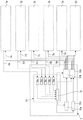
图3为本发明的包含另一替代性等离子体产生器的另一替代性等离子体处理设备的示意图。3 is a schematic diagram of another alternative plasma processing apparatus of the present invention including another alternative plasma generator.
图4(A)至图4(D)为等离子体产生器所发出的脉冲序列,其中图4(A)示出常见等离子体产生器的常规脉冲序列,而图4(B)至图4(D)示出根据图1的等离子体产生器所发出的不同的示例性脉冲序列。4(A) to 4(D) are the pulse sequences issued by the plasma generator, wherein FIG. 4(A) shows the conventional pulse sequence of a common plasma generator, and FIG. 4(B) to FIG. 4( D) shows different exemplary pulse sequences emitted by the plasma generator according to FIG. 1 .
图5(A)至图5(D)为脉冲序列的示意图,其中图5(A)至图5(D)示出根据图2的等离子体产生器所发出的不同的示例性脉冲序列。5(A) to 5(D) are schematic diagrams of pulse sequences, wherein FIGS. 5(A) to 5(D) illustrate different exemplary pulse sequences emitted by the plasma generator according to FIG. 2 .
图6(A)及图6(B)为脉冲序列的示意图,其中图6(A)示出制程室的脉冲序列请求,且图6(B)示出根据图2的等离子体产生器以响应脉冲序列请求的方式发出的示例性脉冲序列。6(A) and 6(B) are schematic diagrams of a pulse sequence, wherein FIG. 6(A) shows a pulse sequence request for a process chamber, and FIG. 6(B) shows a plasma generator according to FIG. 2 in response to An example pulse train issued by means of a pulse train request.
图7(A)及图7(B)为根据图3的等离子体产生器所发出的示例性脉冲序列的示意图,其中两个上下设置的示意图示出在等离子体产生器的不同切换单元上的输出。7(A) and 7(B) are schematic diagrams of an exemplary pulse sequence emitted by the plasma generator according to FIG. 3, wherein two schematic diagrams arranged one above the other show the pulses on different switching units of the plasma generator. output.
图8(A)及图8(B)为脉冲序列的示意图,其中图8(A)示出制程室的脉冲序列请求,且图8(B)示出根据图2的等离子体产生器以响应脉冲序列请求的方式发出的示例性脉冲序列。8(A) and 8(B) are schematic diagrams of pulse sequences, wherein FIG. 8(A) shows a pulse sequence request for a process chamber, and FIG. 8(B) shows a plasma generator according to FIG. 2 in response to An example pulse train issued by means of a pulse train request.
图9(A)及图9(B)为脉冲序列的示意图,其中图9(A)示出制程室的脉冲序列请求,且图9(B)示出根据图2的等离子体产生器以响应脉冲序列请求的方式发出的示例性脉冲序列。9(A) and 9(B) are schematic diagrams of pulse sequences, wherein FIG. 9(A) shows a pulse sequence request for a process chamber, and FIG. 9(B) shows the plasma generator according to FIG. 2 in response to An example pulse train issued by means of a pulse train request.
图10(A)及图10(B)为脉冲序列的示意图,其中图10(A)示出制程室的脉冲序列请求,且图10(B)示出根据图2的等离子体产生器以响应脉冲序列请求的方式发出的示例性脉冲序列。10(A) and 10(B) are schematic diagrams of a pulse sequence, wherein FIG. 10(A) shows the pulse sequence request of the process chamber, and FIG. 10(B) shows the plasma generator according to FIG. 2 in response to An example pulse train issued by means of a pulse train request.
具体实施方式Detailed ways
在本说明书中,表述将实质上包含所述及值的+/-5%(较佳+/-2%)的偏差在内。In this specification, expressions will substantially include a deviation of +/- 5% (preferably +/- 2%) of the stated value.
图1为具有两个制程单元3a、3b以及一等离子体产生器5的等离子体处理设备1的第一实施方式的示意图。制程单元3a及3b可具有相同的结构,并且各具一用于容置一或多个基板、特别是半导体晶圆或PV基板。所述制程室可紧密封闭,且制程单元3a及3b具有不同的用于在各制程室内调节期望的环境条件的构件(未示出),例如泵及气柜。每个制程室同样与一自有的泵对应,而一气柜则可视情况而定对数个制程室进行供给。在所述制程室中还设有用于产生等离子体的构件,其中这些构件例如可由晶圆舟构成,这个晶圆舟例如被与基板一起送入制程室并在该处被电接触,正如在上文述及的DE 10 2015 004 419 A1中所描述的,其就此而言被纳入本公开案。FIG. 1 is a schematic diagram of a first embodiment of a
制程单元3a、3b通过电力线缆7a或7b以及数据连接8a或8b与等离子体产生器5连接。等离子体产生器5通过电力线缆7a、7b将频率大于40KHz的电力提供给各制程单元3a及3b。通过数据连接8a或8b能够在制程单元3a、3b与等离子体产生器5之间交换数据。数据连接8a或8b可采用有线或无线的实施方案。制程单元3a、3b特别是可将有关各制程室中的制程的不同制程数据提供给等离子体产生器5。在此特别是可传输有关实际输入的电力、等离子体的存在等的实际数据,但亦可传输对应的标称数据(Soll-Daten),例如就现有的具有单独一个制程单元及单独一个等离子体产生器的等离子体处理设备而言便是如此。The
等离子体产生器5具有可控制的供电单元10、切换单元12以及控制单元14。所述供电单元具有未示出的输入以及输出,所述输出通过电力线缆15与切换单元12的输入连接。供电单元10配置为以响应控制单元14的控制信号的方式输出具有预定的电压和/或强度的直流电,此为本领域习知。The
切换单元12具有已述及的输入,其与电力线缆15连接,用以自供电单元10接收直流电,以及具有两个分隔的输出,其中一输出与电力线缆7a连接,且另一输出与电力线缆7b连接。切换单元12具有转换器电路,其能够自所述输入上的直流电形成具有预定的至少40KHz频率的交流电作为输出信号。所述转换器电路例如可具有双极晶体管,其自供电单元10所提供的直流电形成准正弦信号(阶梯状信号)。切换单元12还具有切换部件,其将如此形成的输出信号以响应控制单元14的控制信号的方式施加至其中一个或另一输出,藉此施加至制程单元3a或制程单元3b。The switching
如图所示,控制单元14又具有两个分隔的控制器16a、16b,以及电弧抑制单元18。控制器16a、16b通过数据连接8a或8b与制程单元3a或3b连接。控制器16a、16b皆配置为根据有关制程单元3a、3b中的各制程的实际数据及标称数据测定制程单元3a、3b的功率需求。随后,控制器16a、16b(或下游的单元)根据此等功率需求创建用于供电单元10及切换单元12的控制数据。尽管控制器16a、16b被显示为各别独立的单元,但其亦可建构为单独一个单元,所述单元实现制程单元3a及3b的数据的实质上并行的处理。控制器16a、16b特别是可实施为可实质上并行执行的软件常式(Softwareroutinen),这些软件常式在处理器上执行。As shown, the
在所示实施方式中,所述控制器的对应的输出与电弧抑制单元18的对应的输入连接。因此,电弧抑制单元18能够自控制器16a、16b获得各制程单元的功率需求,亦或直接获得据此创建的用于供电单元10及切换单元12的控制数据。此外,电弧抑制单元18亦可直接自各制程单元3a、3b获得未经处理的数据。这类数据特别是为能够实时进行以下评估的数据:判断是否在制程单元3a及3b中的一个中发生了电弧,或者是否即将发生电弧。为此所需的数据以及对应的检测算法已为本领域技术人员所知,故在此不再赘述。在检测出电弧或电弧危险的情况下,电弧抑制单元18能够调整传输至供电单元10及切换单元12的控制信号,并且将对发生电弧或存在对应危险的制程单元3a、3b的电力供应短暂中断。In the embodiment shown, the corresponding outputs of the controllers are connected to corresponding inputs of the
在本实施方式中,电弧抑制单元18还可经建构以使得在获得各制程单元的功率需求数据的情况下据此产生用于供电单元10及切换单元12的控制数据。当然,若已通过控制器16a、16b产生这些控制数据,便无需再采用此方案。此外,电弧抑制单元18是经建构以使得其对自身产生或由控制器16a、16b产生的用于供电单元10及切换单元12的控制数据进行协调。必须如此协调用于供电单元10以及切换单元12的控制数据,从而根据功率需求向各制程单元3a、3b提供功率。但亦需要在时间上对用于供电单元10以及切换单元12的控制数据进行协调,因为在每个时间点上仅能在切换单元的输出中的一个上提供功率。如上文所述,将功率作为具有特定脉冲持续时间的脉冲提供给各制程单元3a、3b。因此,通过用于供电单元10及切换单元12的控制数据对各脉冲进行协调,使得这些脉冲不重叠,其中制程室仍能同步工作。In this embodiment,
图2为等离子体处理设备1的一替代性实施方式的示意图,所述等离子体处理设备在这个实施方式中具有三个制程单元3a、3b、3c,一吸收器20以及一等离子体产生器5。不同实施方式中的相同或相似的元件是用同一元件符号表示。FIG. 2 is a schematic diagram of an alternative embodiment of the
制程单元3a、3b及3c可与上文所述相同,并通过电力线缆7a、7b或7c以及数据连接8a、8b或8c与等离子体产生器5连接。电力线缆7a、7b及7c亦用于将频率大于40KHz的电力自等离子体产生器5提供给各制程单元3a、3b及3c。通过数据连接8a、8b及8c亦能够在制程单元3a、3b、3c与等离子体产生器5之间交换数据。The
等离子体产生器5亦具有可控制的供电单元10、切换单元12以及控制单元14。供电单元10可与前文所述相同。切换单元12亦具有通过电力线缆15与所述供电单元的输出连接的输入。但在这个实施方式中,所述切换单元具有四个分隔的输出,其中这些输出中的三个与电力线缆7a、7b或7c连接,且第四输出通过电力线缆21与所述吸收器连接。The
切换单元12亦具有转换器电路,以及如上文所述的切换部件,其以响应控制单元14的控制信号的方式将通过所述转换器电路形成的输出信号选择性地施加至所述输出中的一个。故能将输出信号选择性地施加至制程单元3a至3c中的一个或施加至吸收器20。The switching
在这个实施方式中,控制单元14亦具有三个分隔的控制器16a、16b及16c,以及一电弧抑制单元18。控制器16a、16b及16c通过各数据连接8a、8b或8c与制程单元3a、3b或3c连接。控制器16a、16b及16c亦可为前文所述类型,其配置为测定各制程单元3a、3b或3c的功率需求,并且视情况而定亦测定用于供电单元10和/或切换单元12的控制数据。In this embodiment, the
电弧抑制单元18亦可实质上为前文所述类型,其中所述电弧抑制单元在这个实施方式中监控三个制程单元3a、3b及3c,以防止电弧。所述电弧抑制单元还对由切换单元12为三个制程单元3a、3b及3c提供的脉冲进行协调。The
在这个实施方式中,电弧抑制单元18还可建构成使得其在获得各制程单元的功率需求的情况下据此产生用于供电单元10及切换单元12的控制数据。当然,若已通过控制器16a、16b产生这些控制数据,便无需再采用此方案。In this embodiment, the
此外,电弧抑制单元18经建构成使得其对自身产生或由控制器16a、16b、16c产生的用于供电单元10及切换单元12的控制数据进行协调。供电单元10以及切换单元12的控制数据必须根据功率需求向各制程单元3a、3b及3c提供功率的协调。但亦需要在时间上对用于供电单元10以及切换单元12的控制数据进行协调,因为在每个时间点上仅能在切换单元的输出中的一个上提供功率。如上文所述,将功率作为具有特定脉冲持续时间的脉冲提供给各制程单元3a、3b及3c。因此,通过用于供电单元10及切换单元12的控制数据对各脉冲进行协调,使得这些脉冲不重叠,其中制程室仍能同步工作。Furthermore, the
尽管将电弧抑制单元18作为既承担电弧抑制功能亦承担脉冲协调功能的单独一个单元示出,但亦可在分隔的单元中实施这些功能。对于电弧抑制功能而言,可为制程室中的每个单独进行对制程数据及控制数据的评估,并可对应地设有三个单元(例如实施为独立的并行的软件常式)。在电弧抑制功能判断出电弧或电弧危险的情况下,其能将原本为制程单元3a、3b及3c中的一个准备的脉冲转送入吸收器20,而非导入各制程单元3a、3b及3c,所述吸收器配置为吸收功率脉冲并例如转换成热。可为整个脉冲或子脉冲进行此切换,下文还将对此进行详细说明。Although
对于脉冲协调功能而言,数据,特别是各制程单元的功率需求或期望的用于供电单元10以及切换单元12的控制数据必须汇集在一协调常式中(Koordinationsroutine)。这种协调常式可如上文所述在电弧抑制单元18中抑或在独立的脉冲协调单元中运行。在所述协调常式中将通过控制器测定的各制程单元的功率需求或据此创建的用于供电单元10及切换单元12的控制数据汇总,并检验是否存在冲突。此外,在这个检验中亦将有关供电单元10以及切换单元12的数据,例如切换时间、最大功率、最大脉冲持续时间(在受限制的情况下)纳入考量。亦可将其他有关各制程单元3a、3b、3c以及运行中的制程的数据纳入考量。这类数据例如可包含脉冲输入中的时间公差、有关脉冲振幅的公差、对制程的最小需要和/或最大允许的能量输入,以及视情况而定包含其他参数。这些数据可在制程范围内保持不变,抑或发生改变。故存在以下制程:在特定时间点上必须遵循具有定义的周期长度以及特定脉冲振幅的精确的脉冲序列,而在这个制程的其他时间点上,周期长度以及脉冲振幅相当灵活,但能量输入在时间范围内位于较窄的公差内。For the pulse coordination function, data, in particular the power requirements of the individual process units or the desired control data for the
根据这些数据,所述协调单元能够对控制单元的输出上的输出脉冲进行协调。较佳的,在各制程单元3a、3b、3c中实施允许设置周期长度(脉冲持续时间与脉冲间隔的和)的制程,所述周期长度相同,或对于制程中的一个而言为另一制程的周期长度的整数倍。正如下文还将结合脉冲图对此进行详细说明的那般,此举将协调大幅简化,但亦并非必需。下文结合脉冲图对不同的协调方案进行详细说明。From these data, the coordination unit is able to coordinate the output pulses on the output of the control unit. Preferably, a process is implemented in each
图3为等离子体处理设备1的另一替代性实施方式的示意图。在这个实施方式中,设有五个制程单元3a至3e,一个吸收器20以及一个等离子体产生器5。不同实施方式中的相同或相似的元件仍用同一元件符号表示。FIG. 3 is a schematic diagram of another alternative embodiment of the
制程单元3a至3e可与上文所述相同,并通过电力线缆7a至7e以及数据连接8a至8e与等离子体产生器5连接。电力线缆7a至7e亦用于将频率大于40KHz的电力自等离子体产生器5提供给各制程单元3a至3e。通过数据连接8a、8b及8c亦能够在制程单元3a、3b、3c与等离子体产生器5之间交换数据。The
在这个实施方式中,等离子体产生器5具有两个可控制的供电单元10a、10b,两个切换单元12a、12b,以及控制单元14。供电单元10a、10b可与前文述及的供电单元相同。就额定功率而言供电单元10a、10b可相同抑或不同。切换单元12a、12b各具一输入,其通过电力线缆15a或15b与所述供电单元中的一个的输出连接。在这个实施方式中,切换单元12a、12b各自具有六个分隔的输出,其中这六个输出中的五个与电力线缆7a至7e、进而与制程单元3a至3e连接,且第六输出通过电力线缆21与吸收器20连接。In this embodiment, the
切换单元12a、12b各具一转换器电路,以及如上文所述具有切换部件,其以响应控制单元14的控制信号的方式将通过所述转换器电路形成的输出信号选择性地施加至所述输出中的一个。故能将每个切换单元12a、12b的输出信号选择性地施加至制程单元3a至3e中的一个或施加至吸收器20。The switching
在这个实施方式中,控制单元14又具有五个分隔的控制器16a至16e,以及电弧抑制单元18。控制器16a至16e通过数据连接8a至8e与制程单元3a至3e连接。控制器16a至16e亦可为前文所述类型,其配置为测定各制程单元3a至3e的功率需求,并且视情况而定亦测定用于供电单元10和/或切换单元12的控制数据。In this embodiment, the
电弧抑制单元18在这个实施方式中监控五个制程单元3a至3e,以防止电弧。所述电弧抑制单元还配置为通过两个供电单元10a、10b以及两个切换单元12a、12b分配以及协调制程单元3a至3e所需的脉冲。The
由于电弧抑制单元18能够将所需脉冲分配至两个电力供应系统(供电单元与切换单元的组合),在脉冲分配方面的灵活性大幅提升。在此情形下,当因功率需求而必要时,特别是亦能提供在时间上重叠的脉冲,下文还将对此进行详细说明。对应的协调需要在切换单元12a或12b上依序提供脉冲,但可如此控制切换单元12a、12b,使得其同时提供脉冲。但在通过分隔的切换单元12a、12b同时提供脉冲的情况下,需要将这些脉冲施加至独立的制程单元3a至3e。Since the
尽管将电弧抑制单元18作为既承担电弧抑制功能亦承担脉冲协调功能的单独一个单元示出,但亦可在分隔的单元中实施这些功能。特别是当协调变得复杂,以及视情况而定对电弧抑制功能造成负面影响时,可在分隔的单元中实施脉冲协调功能。Although
等离子体产生器5亦被作为具有两个分隔的电力供应系统的单独一个等离子体产生器示出。当然,在此亦可设有两个分隔的等离子体产生器5,其各自与制程单元3a至3e以及所述吸收器连接,并且通过共用的控制单元对这些等离子体产生器进行相应的协调。但较佳采用单独一个单元,因为在电弧抑制单元18与供电单元10a、10b以及切换单元12a、12b之间通过实时数据连接实现通讯,这些实时数据连接是机械灵敏的,故应尽可能避免将其铺设在各单元外。The
可为本领域技术人员所理解的是,待供应的制程单元的数目以及等离子体产生器的结构不仅局限于具体示出的实施方式。确切言之,例如如图3所示,还可通过一个等离子体产生器为更多的制程单元进行电力供应。在制程单元的数目较大的情况下,亦可在等离子体产生器中设置例如三个电力供应系统,其中随着制程室以及电力供应系统的数目增大,脉冲协调的复杂度亦增大。但根据本发明,制程单元的数目应高于可用电力供应系统的数目,特别是至少为两倍。It can be understood by those skilled in the art that the number of process units to be supplied and the structure of the plasma generator are not limited to the specific illustrated embodiments. Specifically, for example, as shown in FIG. 3 , more process units can also be powered by one plasma generator. In the case of a larger number of process units, for example, three power supply systems can also be provided in the plasma generator, wherein as the number of process chambers and power supply systems increases, the complexity of pulse coordination also increases. According to the invention, however, the number of process units should be higher than the number of available power supply systems, in particular at least twice as high.
目前例如考虑以下等离子体处理设备:具有八个制程单元(+1可选的吸收器)以及一个等离子体产生器,所述等离子体产生器带有两个分隔的电力供应系统,如图3所示,或具有两个分隔的等离子体产生器以及一个共用的控制单元。For example the following plasma processing plant is currently considered: with eight process cells (+1 optional absorber) and a plasma generator with two separate power supply systems, as shown in Figure 3 shown, or with two separate plasma generators and a common control unit.
对于脉冲协调功能而言,在这个实施方式中亦可汇集与上文所述相同的数据。For the pulse coordination function, the same data as described above can also be collected in this embodiment.
图4(A)至图7(B)示出不同的示例性脉冲序列,这些脉冲序列可通过本发明的等离子体产生器5提供。Figures 4(A) to 7(B) show different exemplary pulse sequences that may be provided by the
图4(A)示出等离子体产生器目前所提供过的经典的脉冲序列。针对预定的例如5ms的持续时间ton输出具有至少40KHz的频率以及预定的功率(P)的交流电脉冲30。之后跟随例如45ms的脉冲间隔toff,在这个脉冲间隔后跟随有持续时间ton例如为5ms的又一脉冲。此为在制程单元中实施等离子体制程时提供的典型的功率脉冲序列。在此情形下产生50ms的周期以及0.1的占空比。因此,所使用的等离子体产生器的可用持续功率的例如90%在此未被利用。FIG. 4(A) shows the classical pulse sequence provided by plasma generators so far. An alternating
图4(B)示出一替代性脉冲序列,本发明的例如如图1所示的等离子体产生器能够提供这个脉冲序列。所述示例性脉冲序列由脉冲30与脉冲40构成,其中例如将脉冲30提供给制程单元3a以及将脉冲40提供给制程单元3b。就这个脉冲序列而言,脉冲30与40各自具有相同的功率以及相同的例如为5ms的脉冲持续时间ton。在脉冲30-30/40-40之间,对于各制程单元3a/3b而言分别有例如45ms的脉冲间隔toff。在脉冲30-40-30之间则产生例如20ms的脉冲间隔toff。每个单独的制程单元3a、3b以0.1的占空比工作,而等离子体产生器则以0.2的占空比工作,故其负荷率显著改善。Figure 4(B) shows an alternative pulse sequence that a plasma generator of the present invention, such as that shown in Figure 1, can provide. The exemplary pulse sequence consists of
图4(C)示出另一示例性脉冲序列,本发明的例如如图1所示的等离子体产生器能够提供这个脉冲序列。所述示例性脉冲序列亦由脉冲30与脉冲40构成,其中例如将脉冲30提供给制程单元3a以及将脉冲40提供给制程单元3b。就这个脉冲序列而言,脉冲30与40各自具有不同的功率,但又如图4(B)所示具有相同的例如为5ms的脉冲持续时间ton以及相同的脉冲间隔。如图所示,所述等离子体产生器不仅能够将相同的脉冲交错,亦能够提供具有不同功率的脉冲,这例如可通过供电单元10的对应控制实现。FIG. 4(C) shows another exemplary pulse sequence that a plasma generator of the present invention, such as that shown in FIG. 1, can provide. The exemplary pulse sequence also consists of
图4(D)示出另一示例性脉冲序列,本发明的例如如图1所示的等离子体产生器能够提供这个脉冲序列。所述示例性脉冲序列亦由脉冲30与脉冲40构成,其中例如将脉冲30提供给制程单元3a以及将脉冲40提供给制程单元3b。就这个脉冲序列而言,脉冲30与40亦如图4(C)所示各自具有不同的功率,并且在此亦具有不同的脉冲持续时间ton,例如对于脉冲30而言为15ms,对于脉冲40而言为5ms。脉冲30-40之间的脉冲间隔分别为例如10ms,且脉冲40-30之间的脉冲间隔分别为例如20ms。可以看出,具有相同的周期长度(或周期长度为彼此的数倍)的用于等离子体制程的脉冲易于交错,并能够通过单独一个等离子体产生器提供。FIG. 4(D) shows another exemplary pulse sequence that a plasma generator of the present invention, such as that shown in FIG. 1, can provide. The exemplary pulse sequence also consists of
但通过单独一个等离子体产生器亦能提供具有不同的并非相互倍数的周期长度的制程。为此,由于在一时间点上仅能为一制程单元提供一脉冲,可采用其中一脉冲和/或另一脉冲的时间上的脉冲偏移,或者脉冲的分割及部分偏移,下文还将结合图6(A)及图6(B)对此进行详细说明。在此试图满足各制程单元的需求,故例如仅在允许的公差内进行偏移/划分。其中,为对电力供应系统(供电单元与切换单元的组合)进行控制,对应的控制单元可对对应的数据进行评估,并视情况而定亦预测一或多个循环,用以预计何时会出现脉冲之间的冲突,从而视情况而定准备偏移。例如,制程中的最大脉冲间隔toff为45ms-50ms的正常脉冲间隔,但在两个循环中需要+10ms的偏移,则可在两个相继的循环中分别进行+5ms的偏移,使得在两个相继的循环中产生50ms的脉冲间隔。但较佳选择偏移为,使得在例如50个循环的较长时间段内,对制程的能量输入对应于功率需求,或者在此时间范围内保持不变。However, processes with different cycle lengths that are not multiples of each other can also be provided by a single plasma generator. To this end, since only one pulse can be provided for a process unit at a time point, a pulse offset in time of one of the pulses and/or the other pulse, or a division and partial offset of the pulse can be used, which will be described below. This will be described in detail with reference to FIG. 6(A) and FIG. 6(B). Here an attempt is made to meet the requirements of the individual process units, so for example only offsets/divisions are made within the allowed tolerances. Among them, in order to control the power supply system (the combination of the power supply unit and the switching unit), the corresponding control unit can evaluate the corresponding data, and also predict one or more cycles depending on the situation to predict when the Conflicts between pulses occur, thereby preparing the offset as appropriate. For example, if the maximum pulse interval t off in the process is a normal pulse interval of 45ms-50ms, but a +10ms offset is required in two cycles, a +5ms offset can be performed in two successive cycles, so that A pulse interval of 50 ms was generated in two consecutive cycles. Preferably, however, the offset is chosen such that the energy input to the process corresponds to the power demand over a longer period of time, eg 50 cycles, or remains constant over this period of time.
图5(A)至图5(D)示出不同的示例性脉冲序列,这些脉冲序列例如可通过根据图2的等离子体产生器5提供。其中例如为不同的制程单元3a至3c提供三个不同的脉冲30、40、50。FIGS. 5(A) to 5(D) show different exemplary pulse sequences, which may for example be provided by the
图5(A)示出包含脉冲30、40、50的脉冲序列,其各自具有相同的例如5ms的脉冲持续时间ton以及相同的功率。在脉冲30-30/40-40/50-50之间,对于各制程单元3a/3b/3c而言分别有例如45ms的脉冲间隔toff。在脉冲30-40-50-30之间产生例如10ms-15ms-10ms的脉冲间隔toff。每个单独的制程单元3a、3b以0.1的占空比工作,而等离子体产生器则以0.3的占空比工作。Figure 5(A) shows a pulse
图5(B)亦示出包含脉冲30、40、50的脉冲序列,但这些脉冲的脉冲持续时间ton以及功率有区别。但脉冲30-30/40-40/50-50又各自具有相同的例如50ms的周期长度,使得脉冲易于交错这些脉冲易于交错。Figure 5(B) also shows a pulse
图5(C)示出另一类似于图5(B)的包含脉冲30、40、50的示例性脉冲序列,这些脉冲的脉冲持续时间ton以及功率有区别。此外,脉冲30-30/40-40各自具有相同的例如50ms的周期长度,而脉冲50-50具有两倍的例如100ms的周期长度。在此情形下亦能轻易实现脉冲的交错。Fig. 5(C) shows another exemplary pulse sequence similar to Fig. 5(B) comprising
图5(D)示出另一类似于图5(B)的包含脉冲30、40、50的示例性脉冲序列,这些脉冲的脉冲持续时间ton以及功率有区别,但脉冲30-30/40-40/50-50又各自具有相同的周期长度。但这个脉冲序列示例性示出电弧抑制单元18对常规脉冲序列的干预。因此,在第二脉冲50的第一半期间已判断出制程单元3c中的电弧,电弧抑制单元18据此对切换单元12进行实时控制,从而将脉冲50的第二半转送入吸收器。此过程足够迅速,并且不会在后续脉冲中产生功率波动,在简单地将制程单元3c自等离子体产生器5分隔时可能会发生功率波动,因为已在切换单元中提供功率。Figure 5(D) shows another exemplary pulse sequence similar to Figure 5(B) comprising
图6(A)中示出三个制程室的示例性脉冲序列需求(功率需求),其例如需要由根据图2的电弧抑制单元18处理及协调,并且在图6(B)中示出示例性脉冲序列,其由根据图2的等离子体产生器以响应所述脉冲序列需求的方式发出。Exemplary pulse train demands (power demands) of three process chambers, which for example need to be processed and coordinated by the
如图6(A)所示,请求具有不同脉冲持续时间以及不同功率的脉冲30、40、50,其中例如通过控制器16a至16c产生对应的请求轮廓。此外,脉冲30-30/40-40/50-50亦具有不同的周期长度,故脉冲序列请求以部分重叠或直接相继的方式请求脉冲。As shown in FIG. 6(A),
由于无法实现这一点,电弧抑制单元18或另一控制单元必须如此对待输出的脉冲进行协调,从而以适当的方式将这些脉冲输出,其中在此将制程单元的需求尽可能纳入考量。在如图6(A)及图6(B)所示的示例中,假定脉冲30不允许经受任何改变,因为对应的制程单元至少在制程的当前相位期间不允许偏差。故输出的脉冲30(参阅图6(B))精确地与所请求的脉冲一致。在总能量输出在时间范围内保持恒定的情况下,制程单元3b及3c中的制程则允许脉冲上的处于预定极限内的偏差。因此,将图6(B)中的第一脉冲50相对其请求(这个请求直接与针对脉冲30的脉冲请求邻接)在时间上略微向前偏移,从而让控制单元12具有缓冲,例如1ms。根据脉冲请求会与脉冲30完全重叠的第二脉冲50在此被划分成两个部分50-1、50-2,其中部分50-1在时间上位于对应的脉冲30前,且部分50-2在时间上被偏移至脉冲30后。在此情形下,子脉冲50-1、50-2的持续时间的总和等于正常脉冲50的持续时间。除这种划分以外,在不会超出脉冲50-50之间最大允许的脉冲间隔的情况下,视情况而定亦可将脉冲50完全偏移至脉冲30后。第三及第四脉冲40亦可经过时间偏移,用以实现合理的脉冲序列。在重叠脉冲中的任一个皆无需在特定时间点上发出的情况下,亦可将两者皆偏移,其中通常逆向偏移。将其中一个向前偏移,而将另一个向后偏移。如此便能视情况而定更佳地保持在腔室的相同脉冲之间请求的脉冲间隔。Since this is not possible, the
图6(A)及图6(B)示出用以根据测定的功率需求以及制程单元的需求产生脉冲序列的不同方案。本领域技术人员能够自本发明的基本原理领会各种脉冲协调方案,这些方案亦可如上文所述为预测式。Figures 6(A) and 6(B) illustrate different schemes for generating pulse sequences based on measured power requirements and process unit requirements. Those skilled in the art will be able to appreciate various impulse coordination schemes from the underlying principles of the present invention, which schemes may also be predictive as described above.
除脉冲的偏移和/或拆分以外,或作为其替代方案,亦可改变各脉冲高度和/或各脉冲持续时间。此方案的示例在图8(A)及图8(B)中示出。图8(A)示出三个制程室的示例性脉冲序列请求(功率需求),而图8(B)示出示例性脉冲序列输出。所述脉冲序列请求特别是与图6(A)相同,且脉冲30再次被视作不可改变。但根据图8(B)的脉冲序列输出有别于根据图6(B)的脉冲序列输出。第一脉冲50并非如图6(B)在时间上向前偏移。确切言之,脉冲起点符合请求。但脉冲在时间上被缩短,为此则将功率增大。由此,在短暂的持续时间内提供更高的功率,使得脉冲的总功率等于或近乎等于请求的功率。第二脉冲50并未被分割,而是被在时间上偏移至重叠请求的脉冲30后。如同第一脉冲50那般,同时在时间上将脉冲缩短并增大功率。与分割相比,上述方案例如有助于在腔室的相继的脉冲之间保持最小化的脉冲间隔。以类似于第一脉冲50的方式对第三脉冲40进行处理,即保持请求的起始时间,而将脉冲持续时间缩短以及将脉冲高度增大。就第四脉冲40而言则将起始时间偏移,但保持根据申请的结束时间。藉此亦缩短脉冲持续时间,这通过增大脉冲高度得到补偿。因此,图8(B)示出一替代性脉冲管理,其在实现与图6(A)相同的输出位置的情况下完全不采用脉冲偏移。在此将起始时间以及结束时间相对请求的偏移视作脉冲偏移。在所述时间点中的至少一个根据请求实施的情况下,不将其视作偏移。In addition to, or as an alternative to, the offset and/or splitting of the pulses, the individual pulse heights and/or the individual pulse durations may also be varied. Examples of this scheme are shown in Figures 8(A) and 8(B). Figure 8(A) shows an example pulse train request (power requirement) for three process chambers, while Figure 8(B) shows an example pulse train output. The pulse train request is in particular the same as in Fig. 6(A) and the
本领域技术人员结合图8(A)及图8(B)能够领会的是,除脉冲的偏移及划分以外,还提供其他用于脉冲协调的方案。当然,亦可将这些方案相互融合,特别是亦可既将脉冲偏移,亦就脉冲高度和/或脉冲持续时间对脉冲进行调变。Those skilled in the art can appreciate with reference to FIG. 8(A) and FIG. 8(B) that, in addition to the offset and division of pulses, other solutions for pulse coordination are also provided. Of course, these schemes can also be combined with each other, in particular both the pulse offset and the pulse modulation with respect to the pulse height and/or the pulse duration can also be performed.
在上述措施中的一个不可行或不妥当的情况下,尽管未示出,亦可将脉冲完全忽略。但在此情形下不应对时间范围内的能量输入造成显著影响。在例如不允许低于每个单位时间(例如毫秒)的最小能量输入的情况下,概念“时间范围内”视情况而定相对较短,因为在此需要将对应的单位时间纳入考量。但例如在实质上关注整体送入制程的能量的情况下,所述概念亦可包括整个制程自身。就较短的时间段而言,例如可在脉冲完全失效或部分失效的情况下视情况而定将前一和/或后一脉冲相应提高或延长。就较长的时间段而言,亦可视情况而定将脉冲大幅延后提供,例如在制程的依照计划的末尾后提供。所述脉冲管理是如此配置,使得在将插入的组件(如供电单元10和/或切换单元12)的性能纳入考量的情况下,为腔室的各种请求选择由脉冲持续时间、脉冲偏移、脉冲功率位准以和/或者脉冲拆分构成的最佳配置。在此将尽可能小的制程影响视作最佳。为了改善恒定能量输入,亦可不仅改变在时间上重叠或邻接的脉冲。所述脉冲管理例如可实施为独立的硬体,或整合至所述控制单元,特别是控制器。In cases where one of the above measures is not feasible or appropriate, although not shown, the pulses can also be ignored entirely. In this case, however, the energy input in the time frame should not be significantly affected. In cases where eg a minimum energy input per unit time (eg milliseconds) is not permitted, the concept "within a time frame" may be relatively short, since the corresponding unit time needs to be taken into account here. However, the concept may also include the entire process itself, for example where the focus is substantially on the energy fed into the process as a whole. For shorter time periods, the preceding and/or succeeding pulses can be increased or lengthened accordingly, as appropriate, for example in the event of complete or partial failure of the pulses. For longer time periods, the pulses may also be provided with a substantial delay, as appropriate, eg after the planned end of the process. The pulse management is configured such that, taking into account the performance of the inserted components (such as the
图7(A)及图7(B)亦示出示例性脉冲序列,其为由根据图3的等离子体产生器通过切换单元12a、12b提供的脉冲序列,其中两个上下设置的示意图示出在所述等离子体产生器的不同切换单元12a、12b上的输出。FIGS. 7(A) and 7(B) also show an exemplary pulse sequence, which is provided by the plasma generator according to FIG. 3 via the
作为功率需求,应提供具有相同脉冲持续时间、相同脉冲之间的周期长度以及相同功率的脉冲30、40、50,其例如到达三个同步实施相同制程的制程单元3a至3c。但此外亦需要产生用于制程单元3d至3e的具有不同脉冲持续时间、脉冲周期以及功率的脉冲60及70,其中每个脉冲70在时间上与脉冲60中的一个重叠。制程单元3d及3e的需求不允许偏移。As power requirements,
在此情形下,所述控制单元发现脉冲的划分,其中切换单元12a主要输出脉冲30、40、50,而切换单元12b主要输出脉冲60及70。但由于切换单元12b不允许将脉冲60及70偏移,而就请求而言在每次需要将脉冲70输出的情况下皆存在重叠,故在通过切换单元12b输出脉冲70的时间点上通过切换单元12a输出所需的脉冲60。如图7(A)及图7(B)所示,无需脉冲30、40及50的偏移便能实现此方案。但在不与制程单元3a至3c的需求抵触的情况下,必要时亦可在脉冲30、40和/或50之间提供空位,用以接收脉冲60。In this case, the control unit finds a division of the pulses, wherein the
如图所示,就脉冲序列的创建而言,根据图3的等离子体产生器5提供较大的灵活性,藉此能够在将各需求纳入考量的情况下满足数个制程单元的功率需求。下面对其他特定脉冲管理方案进行详细说明。As shown, the
采用脉冲关断时间分析(pulse-off-timeUsing pulse-off-time analysis (pulse-off-time analysis)的脉冲偏移analysis) pulse offset
下面对采用脉冲关断时间分析的脉冲偏移方案进行介绍,其中视情况而定,脉冲偏移导致针对同一腔室之后续脉冲的偏移(其中在下文中亦将针对各腔室的脉冲称作通道的脉冲)。在此情形下,下列规则适用:The following describes a pulse shift scheme using pulse off-time analysis, where the pulse shift results in a shift of subsequent pulses for the same chamber, as the case may be (wherein the pulses for each chamber are also referred to below as pulse for the channel). In this case, the following rules apply:
a.不允许改变脉冲长度及脉冲高度。a. It is not allowed to change the pulse length and pulse height.
b脉冲之间的脉冲间隔为最小时间,但可视需要延长。The pulse interval between b pulses is a minimum time, but can be extended as needed.
c.首先请求的脉冲必须首先输出,其他通道上的脉冲必须等待,并且随后被完全输出。不将所产生的脉冲关断时间延长(前一脉冲与经偏移的脉冲之间的经延长的间隔时间)自下一脉冲关断时间减去。因此,将后续脉冲向后偏移,偏移程度为所述脉冲关断时间延长。c. Pulses requested first must be output first, pulses on other channels must wait and then be fully output. The resulting pulse off-time extension (the extended interval between the previous pulse and the offset pulse) is not subtracted from the next pulse off-time. Therefore, subsequent pulses are offset backwards by an amount that extends the off-time of said pulses.
d.在正好同时请求两个脉冲的情况下,首先输出较短的脉冲,随后输出较长的脉冲。若这些脉冲相同,则应首先输出位于第一通道上的脉冲。在有数个通道的情况下,以定义的输出序列进行输出。d. In the case where exactly two pulses are requested at the same time, the shorter pulse is output first, followed by the longer pulse. If the pulses are the same, the pulse on the first channel should be output first. In the case of several channels, the output is performed in a defined output sequence.
e.脉冲的偏移导致脉冲关断时间在一时间段范围内的增大。应据此求出移动平均值。这个值表明时间范围内的整个脉冲关断时间的平均延长。下文将此称作脉冲关断时间增大(Puls-Aus-Zeit-Erh
图9(A)及图9(B)结合一具有两个腔室(通道)的系统示出这个方案,其中图9(A)示出脉冲请求,且图9(B)示出对应的脉冲输出。如图9(A)所示,第三个及第四个请求的脉冲30及40重叠,其中其就第三脉冲发送而言,脉冲30应在脉冲40前开始。故如图9(B)所示,就第三脉冲发送而言,首先输出脉冲30,随后再输出脉冲40。就第四脉冲发送而言,首先输出脉冲40,随后再输出脉冲30。但其中将第四脉冲40相对其请求轮廓向后偏移,偏移时间与第三脉冲向后偏移的程度相同,从而避免第三与第四脉冲之间的间隔时间降至请求的间隔时间(最小间隔时间)以下。因此,在一脉冲发生偏移后,后续脉冲会随之偏移。Figures 9(A) and 9(B) illustrate this scheme in conjunction with a system with two chambers (channels), where Figure 9(A) shows the pulse request and Figure 9(B) shows the corresponding pulse output. As shown in FIG. 9(A),
此方案的优点在于,无需将所产生的从属脉冲的等待时间自间隔时间减去。这样便能避免意外的反馈。但此方案可能会在时间范围内导致脉冲关断时间增大,进而导致功率输出减小。可采用不同的措施来弥补此情形,例如相关腔室中的总制程的与所述移动平均值对应的延长。下文将对其他示例性措施进行说明。The advantage of this scheme is that the latency of the generated slave pulses does not need to be subtracted from the interval time. This avoids unexpected feedback. However, this scheme may result in increased pulse off-time within the time frame, which in turn results in reduced power output. Different measures can be taken to compensate for this situation, such as a prolongation of the overall process in the relevant chamber corresponding to the moving average. Other exemplary measures are described below.
采用脉冲关断时间补偿的脉冲偏移Pulse offset with pulse off-time compensation
为了对在时间段范围内增大的脉冲关断时间进行补偿,可为上述规则a至e补充以下规则。In order to compensate for the increased pulse off time within the time period, the following rules may be supplemented with the above rules a to e.
f.使用者必须输入补偿值,其使脉冲的等待时间减小一固定设定的值。这个值由使用者基于测定的移动平均值选择,并且在制程期间不进行反馈。此方案在以下式中示出。f. The user must enter a compensation value which reduces the waiting time of the pulse by a fixed set value. This value is selected by the user based on the measured moving average and is not fed back during the process. This scheme is shown in the formula below.
脉冲关断时间Puls X=设置的脉冲关断时间Puls X-补偿值Pulse off time Puls X = set pulse off time Puls X - compensation value
在所述移动平均值产生脉冲关断时间的例如2%的延长的情况下,可相应地设置所述补偿值。就2%而言,例如可在设置的脉冲关断时间为50μs的情况下输入1μs的补偿值。在制程期间固定地使用这个补偿值。In the event that the moving average results in an extension of, for example, 2% of the pulse off time, the compensation value can be set accordingly. For 2%, for example, a compensation value of 1 μs can be entered with a set pulse off time of 50 μs. This compensation value is used fixedly during the process.
采用脉冲关断时间补偿的脉冲偏移Pulse offset with pulse off-time compensation
另一对在时间段范围内增大的脉冲关断时间进行补偿的方案为计算相对值。为此可为规则a至e补充以下规则。Another solution to compensate for the increased pulse off time over the time period is to calculate the relative value. The following rules may be supplemented for rules a to e for this purpose.
g.以百分比输入补偿值,其将相继脉冲之间的间隔时间减小,减小程度为介于0%与输入的补偿值之间的随机分配的百分比值。例如在采用10%的情况下,为设置的50μs的脉冲间隔时间产生针对间隔时间的45μs至50μs的窗口。这个值由使用者选择,并且不再进行其他反馈。此方案在以下式中示出。g. Enter a compensation value as a percentage that reduces the interval time between successive pulses by a randomly assigned percentage value between 0% and the entered compensation value. For example, with 10%, a set pulse interval of 50 μs results in a window of 45 μs to 50 μs for the interval. This value is chosen by the user and no further feedback is made. This scheme is shown in the formula below.
脉冲关断时间Puls X=设置的脉冲关断时间Puls X*(100-X)Pulse off time Puls X = set pulse off time Puls X *(100-X)
X在此为介于0%与输入的补偿值之间的单位为%的随机值。在制程期间固定地设置及使用这个值。X is here a random value in % between 0% and the entered compensation value. This value is fixed and used during processing.
采用带反馈的脉冲关断时间补偿的脉冲偏移Pulse offset with pulse off-time compensation with feedback
另一对在时间段范围内增大的脉冲关断时间进行补偿的替代性方案为带反馈的补偿。为了使等离子体产生器更加易用,自动测定、输入以及通过积分调整补偿值。但在某些情形下可能会导致因反馈引起的意外振动。视情况而定可采用预先用以检测及抑制这类可能的振动的算法。Another alternative for compensating for the increased pulse off time over the time period is compensation with feedback. To make the plasma generator easier to use, compensation values are automatically determined, entered, and adjusted by integration. However, in some cases it may cause unexpected vibrations due to feedback. Algorithms pre-designed to detect and suppress such possible vibrations may be employed as appropriate.
为此为上述规则a至e补充以下规则。To this end, the following rules are supplemented to the above-mentioned rules a to e.
h.基于测定的脉冲关断时间延长确定补偿值。为此,将所述脉冲关断时间延长与比例因数K相乘。K可由使用者选择,并且在K<1的情况下相当于阻尼因数,以及在K>1的情况下相当于增益因数。此方案在以下式中示出。h. Determine the compensation value based on the measured pulse off time extension. For this purpose, the pulse off time extension is multiplied by the scaling factor K. K is user selectable and corresponds to the damping factor in the case of K<1 and the gain factor in the case of K>1. This scheme is shown in the formula below.
补偿值=K*脉冲关断时间延长Compensation value = K * pulse off time extension
脉冲关断时间=设置的脉冲关断时间-补偿值Pulse off time = set pulse off time - compensation value
可将这些式应用于每个脉冲。These equations can be applied to each pulse.
采用脉冲时间保持的脉冲偏移Pulse offset with pulse time hold
脉冲时间保持方案用于如上文所述避开功率损失以及复杂的补偿机制。在此采用下列规则:The pulse time keeping scheme is used to avoid power losses and complex compensation mechanisms as described above. The following rules apply here:
a.不允许改变脉冲长度及脉冲高度。a. It is not allowed to change the pulse length and pulse height.
b.通道的相继脉冲之间的间隔时间是灵活的,并可视需要缩短或延长。b. The time interval between successive pulses of a channel is flexible and can be shortened or lengthened as desired.
c.首先将第一个请求的脉冲输出,将位于其他通道上的脉冲在时间上向后偏移(至通道的前一脉冲的脉冲关断时间延长),并且被完全输出。相应地,将脉冲关断时间的延长自至相同通道的下一脉冲的脉冲关断时间减去,从而以经缩短的脉冲关断时间将下一脉冲输出。c. The first requested pulse is output first, the pulses on other channels are shifted backward in time (the pulse off time to the previous pulse of the channel is extended), and it is completely output. Accordingly, the extension of the pulse off time is subtracted from the pulse off time of the next pulse to the same channel, thereby outputting the next pulse with the shortened pulse off time.
因此,在不存在与另一通道的脉冲的重叠的情况下,每个脉冲皆在请求时间点上输出。一脉冲的偏移不会造成相同通道之后续脉冲的偏移。Thus, each pulse is output at the requested time point without overlapping with another channel's pulse. The offset of one pulse does not cause the offset of subsequent pulses of the same channel.
采用优先权的脉冲失效Pulse failure with priority
针对脉冲管理的另一方案为至少部分忽略脉冲,具体方式为,赋予脉冲中的一个以优先权。为此例如产生以下规则:Another approach to pulse management is to at least partially ignore the pulses by giving priority to one of the pulses. For this, the following rules are generated, for example:
a.不允许改变脉冲高度。a. It is not allowed to change the pulse height.
b.脉冲间隔是固定的,且不允许改变。b. The pulse interval is fixed and cannot be changed.
c.输出的脉冲具有优先权列表,且重要的脉冲总是优于不重要的脉冲输出。其中可将低优先权的脉冲完全无效化或仅部分输出。c. The output pulses have a priority list, and important pulses are always output over unimportant pulses. Here, pulses with low priority can be completely disabled or only partially output.
d.测定失效的脉冲的综合并得到脉冲失效总和。d. Determine the sum of failed pulses and obtain the sum of pulse failures.
图10(A)及图10(B)结合具有两个腔室(通道)的系统示出这个方案,其中图10(A)示出脉冲请求,且图10(B)示出对应的脉冲输出。如图10(A)所示,第三个及第四个请求的脉冲30及40重叠。在本示例中,脉冲30具有更高的优先权,故总是如请求的那般被输出,如图10(B)所示。第三及第四脉冲40则被在缩短后输出。就第三脉冲40而言,将开端移至脉冲30的末尾后,而将根据请求轮廓的末尾保持。就第四脉冲40而言,脉冲如请求的那般开始,但提前结束,特别是在重叠请求的脉冲30的请求时间点(以及输出)前。Figures 10(A) and 10(B) illustrate this scheme in conjunction with a system with two chambers (channels), where Figure 10(A) shows the pulse request and Figure 10(B) shows the corresponding pulse output . As shown in FIG. 10(A), the
脉冲的(部分)无效化可能会显著降低功率输入,故在下文中定义了用于解决这个问题的方案。The (partial) nullification of the pulses can significantly reduce the power input, so a solution to this problem is defined below.
采用脉冲数目补偿的脉冲失效Pulse Failure Using Pulse Number Compensation
为了对根据“采用优先权的脉冲失效”方案的(部分)失效的脉冲进行补偿,作为替代方案,可为对应的规则a至d补充以下规则。In order to compensate for (partially) failed pulses according to the "pulse failure with priority" scheme, as an alternative, the following rules may be supplemented to the corresponding rules a to d.
e.基于在d中确定的脉冲失效总和,在调节脉冲序列的末尾输出失效脉冲的数目。e. Based on the pulse failure sum determined in d, output the number of failed pulses at the end of the conditioning pulse train.
由于制程结果通常很大程度上取决于送入的总功率,在脉冲失效不导致制程终止的情况下,例如可通过简单地延长制程时间来对脉冲失效进行补偿。Since process results are often strongly dependent on the total power delivered, pulse failures can be compensated for, for example, by simply extending the process time, provided that pulse failures do not result in process termination.
采用脉冲功率和/或脉冲持续时间补偿的脉冲失效Pulse failure with pulse power and/or pulse duration compensation
为了抑制功率降低,可改变脉冲持续时间和/或脉冲功率,其中脉冲持续时间改变包含相对正常(请求的)脉冲持续时间的偏差,故并非简单的脉冲偏移。在此可如下调整根据“具有优先权的脉冲失效”方案的规则a至d,并通过下列规则进行补充:To suppress power reduction, the pulse duration and/or the pulse power can be varied, wherein the pulse duration variation includes a deviation from the normal (requested) pulse duration, and is therefore not a simple pulse offset. Here, the rules a to d according to the scheme "Impulse failure with priority" can be adjusted as follows, supplemented by the following rules:
a.仅允许在预定的极限内改变脉冲高度。a. Pulse height changes are only allowed within predetermined limits.
b.允许视情况而定在预定的极限内改变、特别是缩短间隔时间。b. Allows to vary within predetermined limits as the case may be, in particular to shorten the interval.
c.输出的脉冲具有优先权列表,且重要的脉冲总是优于不重要的脉冲输出。其中可将低优先权的脉冲完全无效化或仅部分输出。c. The output pulses have a priority list, and important pulses are always output over unimportant pulses. Here, pulses with low priority can be completely disabled or only partially output.
d测定因重叠而失效的脉冲的比例。d Determines the proportion of pulses that fail due to overlap.
e.测定在将间隔时间纳入考量的情况下,能够通过脉冲开端/脉冲末尾的偏移和/或通过在预定的极限内增大脉冲对脉冲的失效比例进行补偿的程度。e. Determining the extent to which the failure ratio of pulses can be compensated for by offsets at the beginning/end of the pulses and/or by increasing the pulses within predetermined limits, taking the interval time into account.
f.将脉冲开端/脉冲末尾偏移,以和/或者在预定的极限内增大脉冲。f. Offset the pulse start/pulse end to and/or increase the pulse within predetermined limits.
相对于脉冲增大,在此例如可优先处理脉冲开端/脉冲末尾的偏移,从而首先试图通过偏移对脉冲的失效比例进行补偿,随后方通过剩余比例的脉冲增大(在能够完整进行的情况下)进行补偿。但亦可规定优先权或设置权重。In this case, for example, a pulse start/pulse end offset can be prioritized over the pulse increase, so that an attempt is made to first compensate for the failure rate of the pulse by the offset, and then the pulse increase of the remaining proportion (in the case where it can be fully carried out). case) to compensate. However, it is also possible to specify priorities or set weights.
当然,亦可仅允许脉冲开端/脉冲末尾的偏移或脉冲增大。Of course, it is also possible to only allow a pulse start/pulse end offset or a pulse increase.
可将上述不同的方案相互组合,从而视具体制程需求为本领域技术人员实现各种方案。The above-mentioned different solutions can be combined with each other, so as to realize various solutions for those skilled in the art depending on the specific process requirements.
前文结合较佳实施方式对本发明进行说明,但本发明不局限于这些具体实施方式。特别是可将所述等离子体产生器用于各种制程单元,且待由等离子体产生器供应电力的制程单元的数目可有别于示出的数目。就根据图3的实施方式而言,切换单元12a、12b亦无需皆与所有制程单元3a至3e连接。因此,例如亦可仅制程单元3a至3c与切换单元12a连接,且制程单元3c至3e与切换单元12b连接,使得仅制程单元3c可由两者控制。这会降低灵活性,但通过两个切换单元总是实现对制程单元中的至少一个的电力供应,从而在脉冲序列建立中化解可能的冲突。The present invention is described above with reference to the preferred embodiments, but the present invention is not limited to these specific embodiments. In particular, the plasma generator can be used for various process units, and the number of process units to be powered by the plasma generator can be different from the number shown. In the case of the embodiment according to FIG. 3 , it is also not necessary for the
Claims (15)
Applications Claiming Priority (6)
| Application Number | Priority Date | Filing Date | Title |
|---|---|---|---|
| DE102017205582 | 2017-03-31 | ||
| DE102017205582.0 | 2017-03-31 | ||
| DE102018204585.2 | 2018-03-26 | ||
| DE102018204585.2A DE102018204585A1 (en) | 2017-03-31 | 2018-03-26 | Plasma generator, plasma treatment apparatus and method for pulsed supply of electrical power |
| PCT/EP2018/058193 WO2018178289A1 (en) | 2017-03-31 | 2018-03-29 | Plasma generator, plasma treatment device, and method for providing electric power in a pulsed manner |
| CN201880023582.1A CN110494949B (en) | 2017-03-31 | 2018-03-29 | Plasma generator, plasma processing apparatus and power pulse supply method |
Related Parent Applications (1)
| Application Number | Title | Priority Date | Filing Date |
|---|---|---|---|
| CN201880023582.1A Division CN110494949B (en) | 2017-03-31 | 2018-03-29 | Plasma generator, plasma processing apparatus and power pulse supply method |
Publications (2)
| Publication Number | Publication Date |
|---|---|
| CN114709126A true CN114709126A (en) | 2022-07-05 |
| CN114709126B CN114709126B (en) | 2025-04-11 |
Family
ID=63524659
Family Applications (2)
| Application Number | Title | Priority Date | Filing Date |
|---|---|---|---|
| CN202210365643.0A Active CN114709126B (en) | 2017-03-31 | 2018-03-29 | Plasma generator, plasma processing equipment and power pulse supply method |
| CN201880023582.1A Expired - Fee Related CN110494949B (en) | 2017-03-31 | 2018-03-29 | Plasma generator, plasma processing apparatus and power pulse supply method |
Family Applications After (1)
| Application Number | Title | Priority Date | Filing Date |
|---|---|---|---|
| CN201880023582.1A Expired - Fee Related CN110494949B (en) | 2017-03-31 | 2018-03-29 | Plasma generator, plasma processing apparatus and power pulse supply method |
Country Status (9)
| Country | Link |
|---|---|
| US (3) | US11355316B2 (en) |
| EP (2) | EP3879558B1 (en) |
| KR (2) | KR102588542B1 (en) |
| CN (2) | CN114709126B (en) |
| DE (1) | DE102018204585A1 (en) |
| MY (1) | MY202814A (en) |
| PL (2) | PL3879558T3 (en) |
| TW (1) | TWI762613B (en) |
| WO (1) | WO2018178289A1 (en) |
Families Citing this family (6)
| Publication number | Priority date | Publication date | Assignee | Title |
|---|---|---|---|---|
| DE102018204585A1 (en) * | 2017-03-31 | 2018-10-04 | centrotherm international AG | Plasma generator, plasma treatment apparatus and method for pulsed supply of electrical power |
| DE102018216969A1 (en) * | 2018-10-03 | 2020-04-09 | centrotherm international AG | Plasma treatment device and method for outputting pulses of electrical power to at least one process chamber |
| DE102018132700A1 (en) * | 2018-12-18 | 2020-06-18 | Krones Ag | Device and method for coating and in particular plasma coating of containers |
| US11239056B2 (en) | 2019-07-29 | 2022-02-01 | Advanced Energy Industries, Inc. | Multiplexed power generator output with channel offsets for pulsed driving of multiple loads |
| DE102022131435A1 (en) | 2022-11-28 | 2024-05-29 | TRUMPF Hüttinger GmbH + Co. KG | Device for generating a plasma flame, plasma generation device, high-temperature processing plant and corresponding operating method |
| CN116095936B (en) * | 2023-02-13 | 2025-12-02 | 南京工业大学 | Device and method for maintaining pulse power control at different plasma discharge stages |
Citations (6)
| Publication number | Priority date | Publication date | Assignee | Title |
|---|---|---|---|---|
| JPH03247748A (en) * | 1990-02-26 | 1991-11-05 | Sumitomo Heavy Ind Ltd | Plasma treating device |
| JPH08153148A (en) * | 1994-11-29 | 1996-06-11 | Nippon Telegr & Teleph Corp <Ntt> | Analog neural network learning circuit |
| CN103890916A (en) * | 2011-09-07 | 2014-06-25 | 朗姆研究公司 | Pulsed plasma chamber with double chamber structure |
| KR20160049628A (en) * | 2014-10-28 | 2016-05-10 | 최도현 | Dual plasma generator, plasma processing system and method therefor |
| KR20160097438A (en) * | 2015-02-06 | 2016-08-18 | 주식회사 원익아이피에스 | Apparatus for supplying plasma power |
| CN110494949A (en) * | 2017-03-31 | 2019-11-22 | 商先创国际股份有限公司 | Plasma generator, plasma processing apparatus and power pulse supply method |
Family Cites Families (49)
| Publication number | Priority date | Publication date | Assignee | Title |
|---|---|---|---|---|
| US3500118A (en) * | 1967-07-17 | 1970-03-10 | Gen Electric | Electrodeless gaseous electric discharge devices utilizing ferrite cores |
| US3657591A (en) * | 1970-06-26 | 1972-04-18 | Gen Electric | High intensity far u.v. radiation source |
| US4017764A (en) * | 1975-01-20 | 1977-04-12 | General Electric Company | Electrodeless fluorescent lamp having a radio frequency gas discharge excited by a closed loop magnetic core |
| US3987335A (en) * | 1975-01-20 | 1976-10-19 | General Electric Company | Electrodeless fluorescent lamp bulb RF power energized through magnetic core located partially within gas discharge space |
| US3987334A (en) * | 1975-01-20 | 1976-10-19 | General Electric Company | Integrally ballasted electrodeless fluorescent lamp |
| US4048541A (en) * | 1976-06-14 | 1977-09-13 | Solitron Devices, Inc. | Crystal controlled oscillator circuit for illuminating electrodeless fluorescent lamp |
| US4180763A (en) * | 1978-01-25 | 1979-12-25 | General Electric Company | High intensity discharge lamp geometries |
| US4431898A (en) * | 1981-09-01 | 1984-02-14 | The Perkin-Elmer Corporation | Inductively coupled discharge for plasma etching and resist stripping |
| US6071572A (en) * | 1996-10-15 | 2000-06-06 | Applied Materials, Inc. | Forming tin thin films using remote activated specie generation |
| US7569790B2 (en) * | 1997-06-26 | 2009-08-04 | Mks Instruments, Inc. | Method and apparatus for processing metal bearing gases |
| US6150628A (en) * | 1997-06-26 | 2000-11-21 | Applied Science And Technology, Inc. | Toroidal low-field reactive gas source |
| US6418874B1 (en) * | 2000-05-25 | 2002-07-16 | Applied Materials, Inc. | Toroidal plasma source for plasma processing |
| US6893907B2 (en) * | 2002-06-05 | 2005-05-17 | Applied Materials, Inc. | Fabrication of silicon-on-insulator structure using plasma immersion ion implantation |
| US7223676B2 (en) * | 2002-06-05 | 2007-05-29 | Applied Materials, Inc. | Very low temperature CVD process with independently variable conformality, stress and composition of the CVD layer |
| US7137354B2 (en) * | 2000-08-11 | 2006-11-21 | Applied Materials, Inc. | Plasma immersion ion implantation apparatus including a plasma source having low dissociation and low minimum plasma voltage |
| US6855906B2 (en) * | 2001-10-16 | 2005-02-15 | Adam Alexander Brailove | Induction plasma reactor |
| SE0302045D0 (en) * | 2003-07-10 | 2003-07-10 | Chemfilt R & D Ab | Work piece processing by pulsed electric discharges in solid-gas plasmas |
| SE532505C2 (en) * | 2007-12-12 | 2010-02-09 | Plasmatrix Materials Ab | Method for plasma activated chemical vapor deposition and plasma decomposition unit |
| WO2009118920A1 (en) * | 2008-03-26 | 2009-10-01 | 株式会社京三製作所 | Abnormal discharge suppressing device for vacuum apparatus |
| US9287086B2 (en) * | 2010-04-26 | 2016-03-15 | Advanced Energy Industries, Inc. | System, method and apparatus for controlling ion energy distribution |
| US8771538B2 (en) * | 2009-11-18 | 2014-07-08 | Applied Materials, Inc. | Plasma source design |
| US8742665B2 (en) * | 2009-11-18 | 2014-06-03 | Applied Materials, Inc. | Plasma source design |
| US8880227B2 (en) * | 2010-05-27 | 2014-11-04 | Applied Materials, Inc. | Component temperature control by coolant flow control and heater duty cycle control |
| DE102010031568B4 (en) * | 2010-07-20 | 2014-12-11 | TRUMPF Hüttinger GmbH + Co. KG | Arclöschanordnung and method for erasing arcs |
| US9065426B2 (en) * | 2011-11-03 | 2015-06-23 | Advanced Energy Industries, Inc. | High frequency solid state switching for impedance matching |
| DE102011009693A1 (en) * | 2011-01-28 | 2012-08-02 | Centrotherm Thermal Solutions Gmbh & Co. Kg | Cooling module and device for the thermal treatment of substrates |
| US8884525B2 (en) * | 2011-03-22 | 2014-11-11 | Advanced Energy Industries, Inc. | Remote plasma source generating a disc-shaped plasma |
| US8952765B2 (en) * | 2012-03-23 | 2015-02-10 | Mks Instruments, Inc. | System and methods of bimodal automatic power and frequency tuning of RF generators |
| US9210790B2 (en) * | 2012-08-28 | 2015-12-08 | Advanced Energy Industries, Inc. | Systems and methods for calibrating a switched mode ion energy distribution system |
| MY187052A (en) * | 2013-03-15 | 2021-08-27 | Plasmability Llc | Toroidal plasma processing apparatus |
| US9336995B2 (en) * | 2013-04-26 | 2016-05-10 | Mks Instruments, Inc. | Multiple radio frequency power supply control of frequency and phase |
| US9514917B1 (en) * | 2013-08-29 | 2016-12-06 | The Boeing Company | Controlled-energy electrical arc systems, methods, and apparatuses |
| US9341610B1 (en) * | 2013-08-29 | 2016-05-17 | The Boeing Company | Electrical arc trigger systems, methods, and apparatuses |
| LT3633683T (en) * | 2014-10-13 | 2021-06-10 | Tae Technologies, Inc. | Method for merging and compressing compact tori |
| TWI670749B (en) * | 2015-03-13 | 2019-09-01 | 美商應用材料股份有限公司 | Plasma source coupled to a process chamber |
| DE102015004419A1 (en) | 2015-04-02 | 2016-10-06 | Centrotherm Photovoltaics Ag | Wafer boat and plasma treatment device for wafers |
| EP3298619A4 (en) * | 2015-05-21 | 2018-12-19 | Plasmability, LLC | Toroidal plasma processing apparatus with a shaped workpiece holder |
| US9721758B2 (en) * | 2015-07-13 | 2017-08-01 | Mks Instruments, Inc. | Unified RF power delivery single input, multiple output control for continuous and pulse mode operation |
| US10395895B2 (en) * | 2015-08-27 | 2019-08-27 | Mks Instruments, Inc. | Feedback control by RF waveform tailoring for ion energy distribution |
| US10636934B2 (en) * | 2015-09-23 | 2020-04-28 | centrotherm international AG | Method and device for passivating defects in semiconductor substrates |
| KR102092213B1 (en) * | 2016-03-23 | 2020-03-23 | 베이징 나우라 마이크로일렉트로닉스 이큅먼트 씨오., 엘티디. | Impedance matching system, impedance matching method and semiconductor process equipment |
| US10187032B2 (en) * | 2016-06-17 | 2019-01-22 | Lam Research Corporation | Combiner and distributor for adjusting impedances or power across multiple plasma processing stations |
| WO2018013681A1 (en) * | 2016-07-14 | 2018-01-18 | Tokyo Electron Limited | Method for rf power distribution in a multi-zone electrode array |
| UA126673C2 (en) * | 2016-11-15 | 2023-01-11 | Тае Текнолоджіз, Інк. | SYSTEMS AND METHODS FOR IMPROVED SUPPORT OF HIGH EFFICIENCY REVERSED FIELD CONFIGURATION AND ELECTRON HEATING BY HIGHER HARMONICS OF FAST WAVES IN HIGH EFFICIENCY REVERSED FIELD CONFIGURATION |
| DE102017206612A1 (en) * | 2017-04-19 | 2018-10-25 | Centrotherm Photovoltaics Ag | Method and device for forming a layer on a semiconductor substrate and semiconductor substrate |
| EP3396698A1 (en) * | 2017-04-27 | 2018-10-31 | TRUMPF Hüttinger GmbH + Co. KG | Power converter unit, plasma processing equipment and method of controlling several plasma processes |
| US10991550B2 (en) * | 2018-09-04 | 2021-04-27 | Lam Research Corporation | Modular recipe controlled calibration (MRCC) apparatus used to balance plasma in multiple station system |
| WO2022146649A1 (en) * | 2020-12-28 | 2022-07-07 | Mattson Technology, Inc. | Directly driven hybrid icp-ccp plasma source |
| TWI829156B (en) * | 2021-05-25 | 2024-01-11 | 大陸商北京屹唐半導體科技股份有限公司 | Plasma source array, plasma processing apparatus, plasma processing system and method for processing workpiece in plasma processing apparatus |
-
2018
- 2018-03-26 DE DE102018204585.2A patent/DE102018204585A1/en active Pending
- 2018-03-29 KR KR1020197032047A patent/KR102588542B1/en active Active
- 2018-03-29 KR KR1020237034119A patent/KR102838071B1/en active Active
- 2018-03-29 PL PL21171624.6T patent/PL3879558T3/en unknown
- 2018-03-29 US US16/498,728 patent/US11355316B2/en active Active
- 2018-03-29 CN CN202210365643.0A patent/CN114709126B/en active Active
- 2018-03-29 EP EP21171624.6A patent/EP3879558B1/en active Active
- 2018-03-29 MY MYPI2019005636A patent/MY202814A/en unknown
- 2018-03-29 EP EP18715016.4A patent/EP3602601B1/en active Active
- 2018-03-29 WO PCT/EP2018/058193 patent/WO2018178289A1/en not_active Ceased
- 2018-03-29 CN CN201880023582.1A patent/CN110494949B/en not_active Expired - Fee Related
- 2018-03-29 PL PL18715016T patent/PL3602601T3/en unknown
- 2018-03-30 TW TW107111399A patent/TWI762613B/en active
-
2022
- 2022-04-28 US US17/731,774 patent/US12087544B2/en active Active
-
2024
- 2024-09-09 US US18/828,021 patent/US20240429026A1/en active Pending
Patent Citations (6)
| Publication number | Priority date | Publication date | Assignee | Title |
|---|---|---|---|---|
| JPH03247748A (en) * | 1990-02-26 | 1991-11-05 | Sumitomo Heavy Ind Ltd | Plasma treating device |
| JPH08153148A (en) * | 1994-11-29 | 1996-06-11 | Nippon Telegr & Teleph Corp <Ntt> | Analog neural network learning circuit |
| CN103890916A (en) * | 2011-09-07 | 2014-06-25 | 朗姆研究公司 | Pulsed plasma chamber with double chamber structure |
| KR20160049628A (en) * | 2014-10-28 | 2016-05-10 | 최도현 | Dual plasma generator, plasma processing system and method therefor |
| KR20160097438A (en) * | 2015-02-06 | 2016-08-18 | 주식회사 원익아이피에스 | Apparatus for supplying plasma power |
| CN110494949A (en) * | 2017-03-31 | 2019-11-22 | 商先创国际股份有限公司 | Plasma generator, plasma processing apparatus and power pulse supply method |
Also Published As
| Publication number | Publication date |
|---|---|
| EP3879558B1 (en) | 2023-11-22 |
| WO2018178289A1 (en) | 2018-10-04 |
| EP3602601A1 (en) | 2020-02-05 |
| KR102588542B1 (en) | 2023-10-11 |
| KR20190130019A (en) | 2019-11-20 |
| PL3602601T3 (en) | 2021-10-25 |
| US20210111001A1 (en) | 2021-04-15 |
| DE102018204585A1 (en) | 2018-10-04 |
| EP3879558A1 (en) | 2021-09-15 |
| US12087544B2 (en) | 2024-09-10 |
| TW201904358A (en) | 2019-01-16 |
| EP3879558C0 (en) | 2023-11-22 |
| US20220254609A1 (en) | 2022-08-11 |
| TWI762613B (en) | 2022-05-01 |
| US20240429026A1 (en) | 2024-12-26 |
| MY202814A (en) | 2024-05-23 |
| EP3602601B1 (en) | 2021-05-05 |
| US11355316B2 (en) | 2022-06-07 |
| CN114709126B (en) | 2025-04-11 |
| KR20230142821A (en) | 2023-10-11 |
| KR102838071B1 (en) | 2025-07-23 |
| CN110494949B (en) | 2022-04-29 |
| CN110494949A (en) | 2019-11-22 |
| PL3879558T3 (en) | 2024-03-25 |
Similar Documents
| Publication | Publication Date | Title |
|---|---|---|
| CN114709126A (en) | Plasma generator, plasma processing apparatus and power pulse supply method | |
| US10971342B2 (en) | Controlling multiple plasma processes | |
| US11430642B2 (en) | Controlling multiple plasma processes | |
| US11538670B2 (en) | Controlling multiple plasma processes | |
| EP1892822B1 (en) | Power level balance of frequency converters connected in parallel | |
| US9634602B2 (en) | Three-phase inverter apparatus and control method thereof | |
| US20140319920A1 (en) | Grid interconnection apparatus | |
| CN111200144B (en) | Current control system, fuel cell system, and control method for boost converter | |
| WO2013145262A1 (en) | Power conversion device | |
| RU2354025C1 (en) | Method for high harmonics compensation and system power factor correction | |
| US10355491B2 (en) | Inverter, in particular as part of a power generation network, and method | |
| US11495972B2 (en) | Selecting switching times of wind turbine converters | |
| RU2413350C1 (en) | Method to compensate high harmonics and correction of grid power ratio | |
| KR20180058483A (en) | Apparatus for inverter | |
| KR102918572B1 (en) | Inverter for circulating current control and method for controlling circulating current using the same | |
| CN101202518A (en) | H-bridge type multi- electrical level inverter using CAN communication | |
| AU2015242113B2 (en) | Power conversion system | |
| KR102527595B1 (en) | Apparatus for inverter | |
| US20260018987A1 (en) | Power converter control device | |
| CN112912989A (en) | Plasma processing apparatus and method of outputting power pulses to at least one processing chamber | |
| JP2008111632A (en) | Heat treatment furnace |
Legal Events
| Date | Code | Title | Description |
|---|---|---|---|
| PB01 | Publication | ||
| PB01 | Publication | ||
| SE01 | Entry into force of request for substantive examination | ||
| SE01 | Entry into force of request for substantive examination | ||
| GR01 | Patent grant | ||
| GR01 | Patent grant |