Positioning method and device
Technical Field
The present application relates to the field of communications technologies, and in particular, to a positioning method and apparatus.
Background
In the 3rd generation partnership project (3 GPP) standard, the positioning technology is generally classified into: radio Access Technology (RAT) dependent positioning technology, radio access technology (RAT-independent positioning technology), and RAT-dependent and RAT-independent combined positioning technology.
The general steps of the positioning technology based on the downlink in the positioning technology of RAT-dependent are as follows: first, a plurality of base stations transmit Positioning Reference Signals (PRS) to a terminal device; then, the terminal device measures the received PRS to obtain a measurement result, for example, one or more of time of arrival (TOA), time difference of arrival (TDOA), and Reference Signal Received Power (RSRP) of the PRS are measured; then, the terminal equipment reports the measurement result to positioning equipment; finally, the positioning device can determine the position information of the terminal device according to the measurement result.
However, the above method cannot meet the high accuracy requirement of the fifth generation communication (5th generation mobile networks, 5G) system for positioning. Therefore, how to improve the positioning accuracy is a problem to be solved in 5G and the next generation mobile communication systems thereof.
Disclosure of Invention
The embodiment of the application provides a positioning method and a positioning device, which can be used for improving positioning accuracy.
In a first aspect, the present application provides a positioning method, including:
the terminal equipment receives information used for indicating a PRS time window of a measurement positioning reference signal from the network equipment; the terminal equipment measures one or more PRSs in a first time window to obtain one or more measurement results; wherein the information indicating a measured PRS time window indicates a start time of the first time window and/or a duration of the first time window; the network device is a positioning device or an access network device.
In the embodiment of the present application, the first time window may be understood as a period of time within the reporting period. The terminal equipment reports the measurement result in the first time window by sending the first time window to the terminal equipment, so that the situation that the positioning accuracy is reduced when the terminal equipment reports the measurement result in the whole period and the measurement result in the whole period is inapplicable or inaccurate is avoided. By further implementing the embodiment of the application, the positioning precision can be effectively improved; meanwhile, the measurement result in the first time window is reported, so that the reporting overhead of the terminal equipment can be effectively reduced.
In a possible implementation manner, the termination time of the first time window is a reporting time at which the terminal device reports the one or more measurement results.
In the embodiment of the present application, the first time window may be understood as a period of time close to the reporting time, so that the terminal device can report the latest measurement result. Meanwhile, in a scene of high-speed movement of the terminal equipment or a scene of relative movement of the terminal equipment and the network equipment, the timeliness of the reported measurement result can be ensured by reporting the latest measurement result, and the positioning precision of the terminal equipment is improved, so that the network equipment can accurately estimate the position of the terminal equipment.
In a possible implementation manner, the information for indicating that the PRS time window is measured includes values of N time windows; each value corresponds to a time window, and each value is used for indicating the starting time of the corresponding time window, or each value is used for indicating the duration of the corresponding time window, and the N time windows include the first time window.
In the embodiment of the application, the network device may further configure the terminal device with values of the N time windows, so that the terminal device may autonomously select the value of the first time window.
In one possible implementation, the method further includes: the terminal device receives an activation signaling from the access network device, where the activation signaling is used to activate one or more values of the N time windows, and the one or more values are used to determine the first time window.
In this embodiment of the present application, after configuring the values of the N time windows for the terminal device, the access network device may further activate one or more of the values of the N time windows, so that the terminal device specifies the value of the first time window.
In one possible implementation, the start time is in any one of a unit of seconds, a frame, a subframe, a slot, a symbol, or a millisecond.
In one possible implementation, the method further includes: the terminal equipment receives the information of the updated time window from the network equipment; and the terminal equipment measures one or more PRSs in the updated time window according to the information of the updated time window.
In one possible implementation, the information indicating that the PRS time window is measured is carried in an assistance information field of long term evolution LTE positioning protocol LPP signaling.
In one possible implementation, the method further includes: the terminal device does not measure the one or more PRSs within the first time window, then the terminal device extends the first time window until one or more PRSs are measured.
In one possible implementation, the method further includes: and the terminal equipment reports a first measurement result, wherein the first measurement result is a measurement result obtained by weighting the one or more measurement results.
In a second aspect, the present application provides a positioning method, including:
the network equipment determines information for indicating a measurement Positioning Reference Signal (PRS) time window; the network equipment sends the information for indicating the measurement of the PRS time window to terminal equipment; wherein the information indicating the measured PRS time window indicates a start time of a first time window and/or a duration of the first time window; the network device is a positioning device or an access network device.
In a possible implementation manner, the termination time of the first time window is a reporting time at which the terminal device reports the one or more measurement results.
In a possible implementation manner, the information for indicating that the PRS time window is measured includes values of N time windows; each value corresponds to a time window, and each value is used for indicating the starting time of the corresponding time window, or each value is used for indicating the duration of the corresponding time window, and the N time windows comprise the first time window.
In one possible implementation, the method further includes: and the access network equipment sends an activation signaling to the terminal equipment, wherein the activation signaling is used for activating one or more values in the values of the N time windows, and the one or more values are used for determining the first time window.
In one possible implementation, the start time is in units of any one of seconds, frames, subframes, slots, symbols, or milliseconds.
In one possible implementation, the method further includes: and the network equipment sends the updated information of the time window to the terminal equipment, wherein the updated information of the time window is used for indicating the update of the first time window.
In one possible implementation, the information for indicating the measured PRS time window is carried in an assistance information field of long term evolution LTE positioning protocol LPP signaling.
In one possible implementation, the method further includes: and the network equipment receives a first measurement result sent by the terminal equipment, wherein the first measurement result is a measurement result obtained by weighting the one or more measurement results.
In one possible implementation, the method further includes: and the network equipment estimates the position information of the terminal equipment according to the first measurement result.
The beneficial effects of the second aspect can be seen in the beneficial effects of the first aspect, which are not described herein in detail.
In a third aspect, the present application provides a communication apparatus, which may be a terminal device, an apparatus in a terminal device, or an apparatus capable of being used in cooperation with a terminal device. Wherein, the communication device can also be a chip system. The communication device may perform the methods of the first aspect and the various possible implementations of the first aspect. The functions of the communication device can be realized by hardware, and can also be realized by executing corresponding software by hardware. The hardware or software includes one or more units corresponding to the above functions. The unit may be software and/or hardware.
In a fourth aspect, the present application provides a communication apparatus, which may be a network device, an apparatus in a network device, or an apparatus capable of being used in cooperation with a network device. Wherein, the communication device can also be a chip system. The communication device may perform the method of the second aspect and various possible implementations of the second aspect. The functions of the communication device can be realized by hardware, and can also be realized by executing corresponding software by hardware. The hardware or software includes one or more units corresponding to the above functions. The unit may be software and/or hardware.
In a fifth aspect, the present application provides a communication device comprising a processor and a memory; the memory is used for storing computer execution instructions; the processor is configured to execute the computer executable instructions to cause the communication device to perform the method as described in the first aspect and the various possible implementations of the first aspect.
In a sixth aspect, the present application provides a communication device comprising a processor and a memory; the memory is used for storing computer execution instructions; the processor is configured to execute the computer executable instructions to cause the communication device to perform the method according to the second aspect and various possible implementations of the second aspect.
In a seventh aspect, the present application provides a communication device comprising a processor, a memory, and a transceiver for receiving signals or transmitting signals; the memory is used for storing program codes; the processor is configured to invoke the program code to perform the method according to the first aspect and various possible implementations of the first aspect.
In an eighth aspect, the present application provides a communication device comprising a processor, a memory, and a transceiver for receiving signals or transmitting signals; the memory is used for storing program codes; the processor is configured to invoke the program code to perform the method according to the second aspect and various possible implementations of the second aspect.
In a ninth aspect, the present application provides a communication device comprising a processor and an interface circuit; the interface circuit is used for receiving code instructions; the processor is configured to execute the code instructions to cause the communication device to perform the method as described in the first aspect and various possible implementations of the first aspect.
In a tenth aspect, the present application provides a communication device comprising a processor and an interface circuit; the interface circuit is used for receiving code instructions; the processor is configured to execute the code instructions to cause the communication device to perform the method according to the second aspect and various possible implementations of the second aspect.
In an eleventh aspect, the present application provides a computer-readable storage medium for storing instructions that, when executed, cause a method as described in the first aspect and various possible implementations of the first aspect to be implemented.
In a twelfth aspect, the present application provides a computer-readable storage medium for storing instructions that, when executed, cause a method as described in the second aspect and various possible implementations of the second aspect to be implemented.
In a thirteenth aspect, the present application provides a computer program product comprising instructions that, when executed, cause the method of the first aspect and various possible implementations of the first aspect to be implemented.
In a fourteenth aspect, the present application provides a computer program product comprising instructions that, when executed, cause the method of the second aspect and various possible implementations of the second aspect to be implemented.
In a fifteenth aspect, the present application provides a computer program for carrying out the first aspect and various possible implementations of the first aspect.
In a sixteenth aspect, the present application provides a computer program for performing the second aspect and various possible implementations of the second aspect.
In a seventeenth aspect, the present application provides a positioning method, including:
the network equipment sends information for indicating measurement of a PRS time window to the terminal equipment; wherein the information indicating the measured PRS time window indicates a start time of a first time window and/or a duration of the first time window; the network equipment is positioning equipment or access network equipment;
and the terminal device receiving information from the network device indicating a measurement positioning reference signal, PRS, time window; the terminal equipment measures one or more PRSs in a first time window to obtain one or more measurement results.
It is understood that, for the methods provided in the present application, reference may also be made to the first aspect and various possible implementations of the first aspect, and various possible implementations of the second aspect and the second aspect, which are not described in detail herein.
Drawings
Fig. 1 is a schematic diagram of determining an angle difference of arrival according to an embodiment of the present application;
fig. 2a is a schematic architecture diagram of a communication system according to an embodiment of the present application;
Fig. 2b is a schematic architecture diagram of a communication system according to an embodiment of the present application;
FIG. 3 is a schematic view of a measurement model provided in an embodiment of the present application;
FIG. 4 is a diagram illustrating a PRS configuration provided in an embodiment of the present application;
fig. 5 is a schematic diagram of UE measurement data provided in an embodiment of the present application;
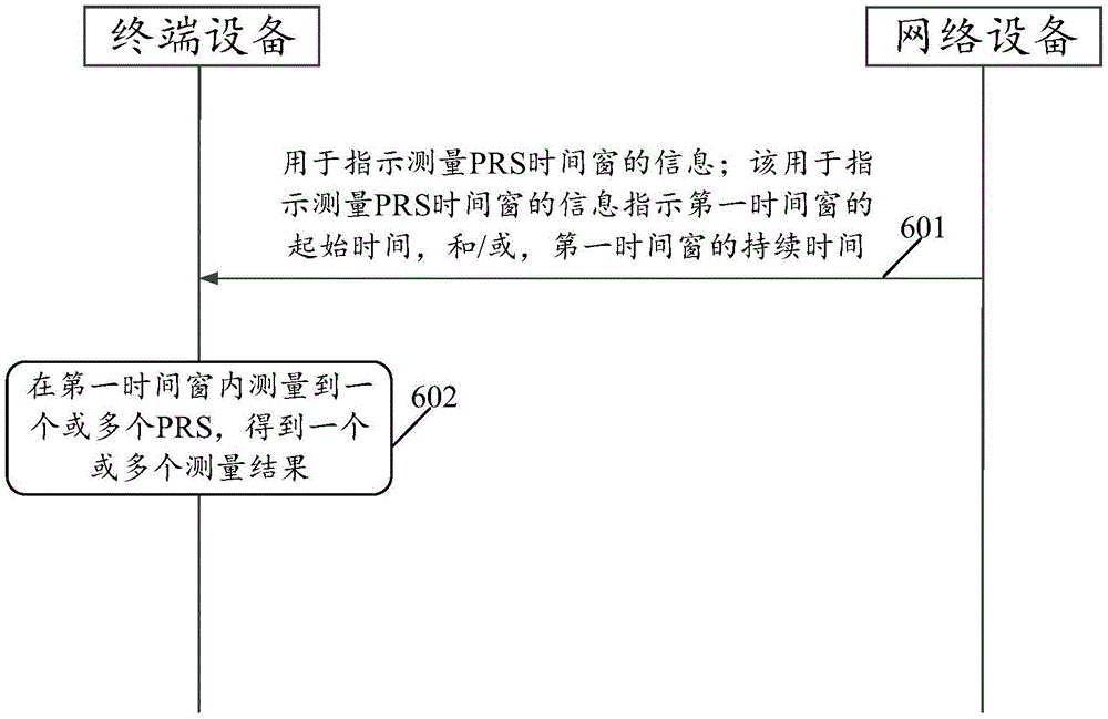
fig. 6 is a schematic flowchart of a positioning method according to an embodiment of the present application;
FIG. 7a is a schematic configuration diagram of a first time window provided in an embodiment of the present application;
FIG. 7b is a schematic configuration diagram of a first time window provided in an embodiment of the present application;
FIG. 7c is a schematic configuration diagram of a first time window provided by an embodiment of the present application;
fig. 8 is a schematic view of a positioning method provided in an embodiment of the present application;
fig. 9 is a schematic view of a positioning method provided in an embodiment of the present application;
fig. 10a is a schematic view of a positioning method provided in an embodiment of the present application;
fig. 10b is a schematic view of a scenario of a positioning method according to an embodiment of the present application;
fig. 11a is a schematic view of a scenario of a positioning method according to an embodiment of the present application;
fig. 11b is a schematic view of a scenario of a positioning method according to an embodiment of the present application;
Fig. 12 is a schematic view of a positioning method provided in an embodiment of the present application;
fig. 13 is a schematic structural diagram of a communication device according to an embodiment of the present application;
fig. 14 is a schematic structural diagram of a communication device according to an embodiment of the present application;
fig. 15 is a schematic structural diagram of a terminal device according to an embodiment of the present application;
fig. 16 is a schematic structural diagram of a communication device according to an embodiment of the present application.
Detailed Description
In order to make the objects, technical solutions and advantages of the present application more clear, the present application will be further described in detail with reference to the accompanying drawings.
The terms "first" and "second," and the like in the description, claims, and drawings of the present application are used for distinguishing between different objects and not for describing a particular order. Furthermore, the terms "include" and "have," as well as any variations thereof, are intended to cover non-exclusive inclusions. For example, a process, method, system, article, or apparatus that comprises a list of steps or elements is not limited to only those steps or elements listed, but may alternatively include other steps or elements not listed, or inherent to such process, method, article, or apparatus.
Reference herein to "an embodiment" means that a particular feature, structure, or characteristic described in connection with the embodiment can be included in at least one embodiment of the application. The appearances of the phrase in various places in the specification are not necessarily all referring to the same embodiment, nor are separate or alternative embodiments mutually exclusive of other embodiments. It is explicitly and implicitly understood by one skilled in the art that the embodiments described herein can be combined with other embodiments.
In this application, "at least one" means one or more, "a plurality" means two or more, "at least two" means two or three and three or more, "and/or" for describing an association relationship of associated objects, which means that there may be three relationships, for example, "a and/or B" may mean: only A, only B and both A and B are present, wherein A and B may be singular or plural. The character "/" generally indicates that the former and latter associated objects are in an "or" relationship. "at least one of the following" or similar expressions refer to any combination of these items, including any combination of single item(s) or plural items. For example, at least one (one) of a, b, or c, may represent: a, b, c, "a and b", "a and c", "b and c", or "a and b and c", wherein a, b, c may be single or plural.
For a better understanding of the solutions provided in the present application, the following first introduces the related terms to which the present application refers:
positioning Reference Signal (PRS): the reference signal is sent to the receiving end by the transmitting end and used for the positioning function. For example, a network device can periodically transmit a PRS, which a terminal device can periodically receive. It can be understood that, during the process of receiving the PRS by the terminal device, the terminal device may measure at least one of a time difference of arrival, an angle difference of arrival and a reference signal received power of the PRS to obtain a measurement result. And the network equipment or the terminal equipment obtains a positioning result based on the measurement result. In keeping with this, the following describes the reception of PRS by a terminal device collectively as the terminal device measuring PRS.
Time difference of arrival (TDOA): refers to the difference of the arrival time of the reference signals (such as PRS) sent by different network devices and received by the terminal device.
Angle difference of arrival (angle difference of arrival, ADOA): refers to the difference of the arrival angles of the reference signals (such as PRS) transmitted by different network devices and received by the terminal device. As an example, as shown in fig. 1, a base station 2, and a base station 3 may respectively transmit PRS to terminal devices, where an arrival angle 1, an arrival angle 2, and an arrival angle 3 may be obtained with reference to a horizontal line. If the arrival angle 1 is taken as a reference angle, the arrival angle difference can be the difference value between the arrival angle 1 and the arrival angle 2; angle of arrival 1 and angle of arrival 3. It is understood that the angle of arrival shown in fig. 1 is only an example, and in a specific implementation, there may be other methods for determining the angle of arrival difference, and the embodiment of the present application is not limited thereto.
Reference Signal Received Power (RSRP): is defined as the linear average (unit: W) of the power of the resource element (resource element) carrying the reference signal within the measurement frequency bandwidth.
Reporting time: the network device configures or protocols predefined time for reporting the measurement result. For example, the network device configures a reporting period to be 8 time slots, and the 1 st time slot and the 9 th time slot are one reporting time.
The network architecture to which the present application relates will be described in detail below.
The methods provided by the present application may be applied to various communication systems, for example, an internet of things (IoT) system, a narrowband band internet of things (NB-IoT) system, a Long Term Evolution (LTE) system, a fifth generation (5th-generation, 5G) communication system, a hybrid architecture of LTE and 5G, a next generation communication system (e.g., 6G), and the like. The method provided by the embodiment of the present application can be used whenever positioning information of a reference signal within a period of time needs to be measured in a communication system.
Referring to fig. 2a, fig. 2a is a schematic structural diagram of a communication system according to an embodiment of the present disclosure. As shown in fig. 2a, the communication system comprises a terminal device and at least one network device.
In a possible implementation manner, the network device is an access network device, that is, the location information of the terminal device may be determined by the access network device. For example, the access network device may comprise an access network device of a serving cell of the terminal device and/or at least one access network device of a neighboring cell.
The access network device may be a device capable of communicating with the terminal device. The access network device may be any device with wireless transceiving capabilities, including but not limited to a base station. For example, the base station may be the next generation Node B (gNB), or the base station may be a base station in a future communication system. Optionally, the access network device may also be an access node, a wireless relay node, a wireless backhaul node, and the like in a wireless local area network (WiFi) system. Optionally, the access network device may also be a wireless controller in a Cloud Radio Access Network (CRAN) scenario. Optionally, the access network device may also be a wearable device or a vehicle-mounted device. Optionally, the access network device may also be a small station, a transmission node (TRP) (or may also be referred to as a transmission receiving point), and the like. It is understood that the access network device may also be a base station in a Public Land Mobile Network (PLMN) for future evolution, and the like.
In one possible implementation, the network device is a positioning device, that is, the positioning device determines the location information of the terminal device. The positioning device may be a network element capable of implementing a positioning management function on the core network side. For example, the location device may be a Location Management Function (LMF) network element, a Location Management Unit (LMU), a Location Management Center (LMC), or an evolved serving mobile location center (E-SMLC). It is understood that the positioning device may also be other devices for determining location information of the terminal device, and the name of the positioning device is not limited in the embodiments of the present application.
A terminal device may also be referred to as a User Equipment (UE), a terminal, or the like. The terminal equipment has a wireless transceiving function, can be deployed on land and comprises an indoor or outdoor, a handheld, a wearable or a vehicle-mounted terminal; can also be deployed on the water surface, such as a ship and the like; it may also be deployed in the air, such as on an airplane, balloon, or satellite, etc. The terminal device may be a mobile phone (mobile phone), a tablet computer (Pad), a computer with wireless transceiving function, a Virtual Reality (VR) terminal device, an Augmented Reality (AR) terminal device, a wireless terminal in industrial control (industrial control), a wireless terminal in self driving (self driving), a wireless terminal in remote medical (remote medical), a wireless terminal in smart grid (smart grid), a wireless terminal in transportation safety (transportation safety), a wireless terminal in smart city (smart city), a wireless terminal in home (smart home), and so on. It is to be understood that the terminal device may also be a terminal device in a future 6G network or a terminal device in a future evolved PLMN, etc.
As an example, commonly used algorithms for estimating location information include trilateration or triangulation, i.e. estimating the location of an object by calculating the intersection of several circles around different base stations. Let t
i(i-1, … N) is defined as the product of the transmission time of the reference signal from the base station i to the UE and the speed of light, b
iDefined as the coordinates, x, of base station i
UEDefined as the sitting of the UETarget (i.e., the location of the UE), ω is defined as the product of the time error and the speed of light, if it is assumed that every t
iAll obey independent Gaussian distributions and have variances of
Mean value of ω + | b
i-
UEIif, then its Probability Distribution Function (PDF) formula is as (1):
the result of least squares estimation for the above equation is shown in equation (2):
it is understood that the above method for estimating the location information of the terminal device is provided only for the embodiments of the present application, and in particular implementations, other methods may be further included, such as hyperbolic positioning method, fingerprint positioning method, or particle filter positioning method, and for the particular implementations of these methods, the embodiments of the present application are not described in detail.
Referring to fig. 2b, fig. 2b is a schematic structural diagram of a communication system according to an embodiment of the present disclosure. The communication system includes UEs, a gNB1, a gNB2, and a gNB 3. The gNB1, the gNB2, and the gNB3 may respectively periodically transmit the PRS, and the UE may periodically receive the PRS, measure the positioning information of the PRS, and obtain the measurement result. For example, the UE may measure one or more of TDOA, ADOA, or RSRP of the PRS, to which the present application is not limited for positioning information of the PRS. Further, the UE may also report the measurement result. As an example, for how the UE gets the measurement results, reference may be made to fig. 3. It can be understood that the embodiments of the present application do not limit how the UE measures TDOA, ADOA, RSRP, or the like of the PRS.
Referring to fig. 3, fig. 3 is a schematic view of a measurement model provided in the embodiment of the present application. In fig. 3, point a is input measurement data (i.e., positioning information of PRS), point B is data filtered by layer 1, point C is data filtered by layer 3, and point D is data finally reported to the network device. The layer 3 filtering formula is shown in equation (3):
F n=(1-a)·F n-1+a·M n (3)
wherein, MnThe nth measurement result from the physical layer (which can also be understood as the weighted result of the measurement data in the nth reporting period) corresponds to point B in fig. 3. As an example, MnMay be an average of the measured data. FnThe result of the nth measurement, namely the output result of the point C in FIG. 3; fn-1The result of the n-1 st measurement. As an example, when measuring for the first time, F0Is set as M1. Wherein, a is 1/2(k/4)And k is called a filter coefficient, if k is 0, the filtering is not performed by the layer 3, and the size of k corresponds to the proportion of the n-1 th measurement result in the nth measurement result. As can be appreciated,
for the measurement reporting process of PRS, if the above model is adopted, first, layer 1 filtering (averaging) is performed on the measurement results of N PRS occases in fig. 3 to obtain Mn(ii) a Then, layer 3 filtering is carried out by using a formula (3), and finally F is reported n。
In practical applications, when the UE performs measurement, the UE does not report the PRS signal by measuring only one time, but performs multiple measurements on PRS signals from different base stations, and then reports the PRS signals at a fixed reporting time. The PRS may be sent periodically with various choices for the size of the period. For example, a period of a PRS in a New Radio (NR) may be configured to be 2μ{4,8,16,32,64,5,10,20,40,80,160,320,640,1280,2560,5120,10240,20480} slots, μ ranges from {0,1,2,3,4 }. Besides, when scanning a downlink beam, the PRS may be configured to be repeatedly transmitted, i.e., there may also be PRS transmission during a configured periodic interval. As an example, as shown in FIG. 4, although the periodicity of the PRS is configured to be8 slots (slots), but within the 8 slots, the base station may repeatedly transmit PRSs. As shown in fig. 4, if the repetition number is 4 and the repetition interval is 2 slots, the base station can repeatedly transmit PRS in 8 slots. It is understood that the repeated transmission herein means that one PRS resource can be repeatedly transmitted using the same beam.
In fig. 4, PRS (primary reference signal) transmitted by one base station is shown, but actually, the UE needs to receive PRS (primary reference signal) of a plurality of base stations (e.g., at least three base stations) in the same time period to be able to position effectively. That is, the UE needs to measure a large number of PRSs in the same time period. As shown in fig. 5, the measurement of multiple PRSs in the same time period is regarded as one occase (e.g., receiving the PRS transmitted by the gNB1, the PRS transmitted by the gNB2, and the PRS transmitted by the gNB 3). Then between reporting time n and reporting time n +1, the UE has measured multiple sets of data.
As can be seen from fig. 5, before the reporting time, the UE has measured multiple sets of data, and the content of the data includes the arrival time of the PRS, the arrival time difference of different PRSs, the received powers of different PRSs, and the like.
The UE needs to measure all PRSs before reporting, and then performs layer 1 filtering, where the layer 1 filtering method is to take an average value. But the UE is in a high speed scenario or a relative positioning scenario (both the transceiver and the transmitter are moving), the location of the receiver and the transmitter changes at the moment of transmission, and then some of the previous measurements may not be applicable or fail. At this time, if the UE of the receiving party still reports all the previous measurement results at the reporting time, not only the measurement resources are wasted, but also the final positioning accuracy is reduced due to the addition of the inapplicable measurement values.
Therefore, the positioning method can avoid waste of measurement resources and improve positioning accuracy. The positioning method provided in the present application will be described in detail below.
Referring to fig. 6, fig. 6 is a schematic flowchart of a positioning method according to an embodiment of the present disclosure. As an example, the positioning method may be applied to the communication system shown in fig. 2a and/or fig. 2 b. As an example, the localization method may also be applied to the relevant background models described in fig. 3-5. As an example, the network device in the embodiment of the present application may be an access network device or a positioning device, and reference may be made to fig. 2a for specific description of the access network device and the positioning device, which is not described in detail here.
As shown in fig. 6, the positioning method includes:
601. the network equipment sends information for indicating measurement of a PRS time window to the terminal equipment; wherein the information indicating the measured PRS time window indicates a start time of the first time window and/or a duration of the first time window. Accordingly, the terminal device receives the information indicating the measured PRS time window.
In the embodiment of the present application, the first time window may be understood as a period of time between two reporting times. It can be understood that the reporting time is related to a reporting period, for example, the reporting period is 4 timeslots, and from the initial reporting time, every 4 timeslots are the reporting time.
As an example, the information indicating the measured PRS time window may include a start time of a first time window, in which case a termination time of the first time window may be preconfigured; alternatively, the information indicating the measured PRS time window may further include a termination time of the first time window; or the termination time of the first time window is the reporting time of the terminal equipment reporting one or more measurement results. Wherein, the termination time can be configured in advance by the terminal equipment; alternatively, the termination time may also be preconfigured by the network device, and the embodiment of the present application is not limited. The terminal equipment can report the latest measurement result by setting the termination time of the first time window as the reporting time of the terminal equipment reporting one or more measurement results, so as to ensure the timeliness of the reported measurement result.
As an example, the information indicating the measured PRS time window may include a duration of a first time window, in which case a termination time and/or a start time of the first time window may be preconfigured; alternatively, the information indicating the measured PRS time window may further include a start time or an end time of the first time window; or the starting time or the ending time of the first time window is the reporting time when the terminal device reports one or more measurement results.
As an example, the information indicating the measured PRS time window may include a start time and a duration of the first time window. By the method, the terminal equipment can definitely know the measurement result in which time period is reported.
For example, referring to fig. 7a, the first time window can be understood as a period of time between the reporting time n and the reporting time n + 1. The terminal equipment can effectively reduce the size of the reported data volume by reporting the measurement result in the first time window, thereby reducing the signaling overhead. Referring to fig. 7b, the ending time of the first time window is the same as the next reporting time. The terminal equipment can report the latest measurement result in a scene of high-speed movement by reporting the measurement result in the first time window, so that the validity of the reported data is ensured.
In one possible implementation, the information indicating that the PRS time window is measured includes values of N time windows; each value corresponds to a time window, and each value is used for indicating the starting time of the corresponding time window, or each value is used for indicating the duration of the corresponding time window, and the N time windows include the first time window.
By way of example, the N time windows include a first time window, a second time window, a third time window, and so on. That is, the information indicating that the PRS time window is measured includes a value of the first time window, a value of the second time window, a value of the third time window, and so on. The value of the first time window may be used to indicate a start time or duration of the first time window, the value of the second time window may be used to indicate a start time or duration of the second time window, the value of the third time window may be used to indicate a start time or duration of the third time window, and so on. It is understood that the value of the first time window may also be an index of the start time of the first time window. For example, the values of the N time windows are { T }1,T 2,T 3,…,T nIt can be as follows:
example 1: {4,8,12,16,20,24,28,32,36,40,44,48 };
Example 2: {5,10,15,20,25,30,35,40,45,50,55,60 };
example 3: {8,16,24,32,40,48,56,64,72,80,88,96 };
example 4: {4,8,16,32,64,5,10,20,40,80,160,320,640,1280,2560,5120,10240,20480}.
It is understood that the values in the various examples above may be a start time or a duration. It is understood that the values in the above examples may also be an index of start time or an index of duration. For example, index 4 of the start time may correspond to start time slot 4; for another example, the index 8 of the start time may correspond to the start time slot 5, and the like, and the index relationship is not limited in the embodiment of the present application.
In the embodiment of the present application, the unit of the start time is any one of a second, a frame, a subframe, a slot, a symbol, and a millisecond. And the unit of the termination time is any one of a second, a frame, a subframe, a slot, a symbol, or a millisecond. It is understood that the value of the start time may be any one of a second index, a frame index, a subframe index, a slot index, a symbol index, or a millisecond index.
In an embodiment of the present application, information for indicating measurement of a PRS time window may be carried in an auxiliary information field, which may be carried in a signaling, and the auxiliary information field is used for indicating a request for positioning auxiliary information. For example, the information indicating the measured PRS time window may be carried in an assistance information field of Long Term Evolution (LTE) positioning protocol (LPP) signaling.
In one possible implementation, the method shown in fig. 6 further includes:
the method comprises the steps that an access network device sends an activation signaling to a terminal device, correspondingly, the terminal device receives the activation signaling from the access network device, the activation signaling is used for activating one or more values in values of N time windows, and the one or more values are used for determining a first time window.
The terminal equipment can definitely know which measurement result in which time window is reported by sending the activation signaling to the terminal equipment. It is understood that, for the specific implementation of the activation signaling, reference may be made to the corresponding description in the following embodiments, which are not detailed here first.
In one possible implementation, before the network device sends information indicating that the PRS time window is measured to the terminal device, the method shown in fig. 6 further includes:
the network device determines information indicating a measured PRS time window.
Optionally, the network device may carry the information indicating the measured PRS time window according to a format of LPP signaling.
602. The terminal equipment measures one or more PRSs in the first time window to obtain one or more measurement results.
In one possible implementation, the method shown in fig. 6 may further include:
If the terminal device does not measure one or more PRSs within the first time window, the first time window is extended until one or more PRSs are measured.
Referring to fig. 7c, if the terminal device does not measure one or more PRSs in the first time window in fig. 7c, the terminal device may extend the duration of the first time window (the extended duration is shown by the dashed line in fig. 7 c) until one or more PRSs are measured. It is understood that, for the specific time period extended by the terminal device, the embodiment of the present application is not limited.
Optionally, the terminal device may delay by a multiple of the first time window, thereby increasing the implementation efficiency, so that when the terminal device does not measure one or more PRSs within the first time window, the duration of the extended time window can be quickly determined.
In one possible implementation, the method shown in fig. 6 may further include:
and the terminal equipment reports a first measurement result, wherein the first measurement result is a measurement result obtained by weighting one or more measurement results. Accordingly, the network device receives the first measurement result.
It is understood that the first measurement result may be an average value obtained by weighting one or more measurement results, and the embodiment of the present application is not limited to how to weight the measurement results. That is, the first measurement result may be a weighted result of the measurement results measured by the terminal device within the first time window.
For example, the related descriptions of PRS in the embodiments of the present application may refer to fig. 3-5. For example, the terminal device may periodically measure positioning information of the PRS to obtain a measurement result. As another example, the network device may also repeatedly transmit PRSs. For another example, the terminal device may further obtain a measurement result based on the model shown in fig. 3, or the terminal device may further obtain a measurement result based on another model, and the like, which is not limited in this embodiment of the application. It is understood that the following embodiments are equally applicable to the related description of the PRS.
In one possible implementation, the method shown in fig. 6 may further include:
and the network equipment estimates the position information of the terminal equipment according to the first measurement result.
In the embodiment of the present application, how the network device estimates the location information of the terminal device according to the first measurement result reported by the terminal device is not limited. For how to estimate the location information of the terminal device, reference may be made to the foregoing formula (1) and formula (2), or the location information may also be estimated according to other methods, and the like, and the embodiment of the present application is not limited.
In one possible implementation, the method shown in fig. 6 may further include:
the network equipment sends the information of the updated time window to the terminal equipment, and the terminal equipment receives the information of the updated time window from the network equipment;
And the terminal equipment measures one or more PRSs in the updated time window according to the information of the updated time window.
The network device may update the time window according to the motion state of the terminal device, or the network device may update the time window periodically, and so on. For a detailed description of the information for updating the time window, reference may be made to the following embodiments, which are not described in detail here.
It can be understood that, in the embodiment of the present application, no limitation is imposed on whether the terminal device measures PRS of other times than the first time window, where the other times and the first time window belong to the same reporting period. As an example, the terminal device may not measure PRS for the other times, thereby reducing measurement overhead for the terminal device and saving power consumption.
By implementing the embodiment of the application, the terminal equipment reports the measurement result in the first time window, so that the waste of measurement resources can be avoided, and the signaling overhead is reduced. Especially for a scene of high-speed movement of the terminal equipment or a scene of relative positioning change of the terminal equipment and the network equipment, reporting of an inapplicable measurement result can be avoided by reporting the measurement result in the first time window, so that timeliness of data is ensured, and positioning accuracy is improved.
Taking a terminal device as a UE as an example, referring to fig. 6, the size of the first time window (e.g. T) in fig. 6 may be configured to the UE by an LMF or a base station through high-layer signaling, and the size of T may change dynamically, for example, when the UE and the base station are in a relatively static state, T may be configured to a larger value, so as to ensure robustness of multiple measurements; when the UE and the base station are in a relative motion state, T may be configured to be a smaller value, so as to ensure timeliness of the reported data. No matter what the value of T is, the UE only needs to measure and report the PRS included in the first time window, so that the measurement overhead of the UE can be reduced, and the positioning performance loss caused by the inaccuracy of the reported measurement result can be avoided.
To better understand the method shown in fig. 6, the above positioning method will be described below by taking a specific embodiment as an example.
The first embodiment,
Please refer to fig. 8, fig. 8 is a schematic scene diagram of a positioning method according to an embodiment of the present disclosure. As shown in fig. 8, the positioning method includes:
801. the UE sends LPP signaling to the LMF requesting location assistance information. Accordingly, the LMF receives the LPP signaling for requesting the positioning assistance information.
802. The LMF sends LPP signaling including values { T1, T2, T3, T4, …, Tn } for the N time windows to the UE. Correspondingly, the UE receives the LPP signaling including the values of the N time windows.
It is understood that the values of the N time windows are carried in an assistance information field (or may also be referred to as a positioning assistance information field) in the LPP signaling.
As an example, the LPP signaling may further include one or more of a configuration information field of a PRS, an information field of a reference cell, and an information field of a neighbor cell, and a specific format of the LPP signaling is not limited in the embodiment of the present application.
803. The LMF sends NRPPa signaling comprising values of N time windows to the base station. Correspondingly, the base station receives the NRPPa signaling including the values of the N time windows.
That is to say, the LMF configures N time windows for the UE, and the LMF may also notify the base station of the configuration of the N time windows, so that the base station may activate one time window as the first time window in the values of the N time windows.
It is understood that the values of the N time windows include the start times of the N time windows or the durations of the N time windows, and the detailed description may refer to fig. 6, which is not described in detail herein.
804. The base station transmits media access control-control element (MAC-CE) signaling including a start time or duration of the first time window to the UE. Accordingly, the UE receives the MAC-CE signaling.
It is to be understood that the MAC-CE signaling comprising the first time window may also be understood as signaling for activating the first time window. That is, the LMF configures N time windows from which the base station may select one to activate. The embodiment of the present application is not limited as to which time window is selected by the base station for activation. For example, the base station may determine which time window to activate according to the approximate moving speed of the UE, for example, if the moving speed of the UE is fast, the time window with a shorter duration may be activated; for another example, if the UE moves at a slower speed, a longer time window may be activated. As an example, the base station may further determine which time window to activate according to an approximate relative speed between the UE and the base station, and if there is no significant relative motion between the UE and the base station, the base station may activate the time window with a longer duration; in another example, if there is significant relative motion between the UE and the base station, a shorter time window may be activated.
It is understood that, for the MAC-CE signaling in 804, Downlink Control Information (DCI) signaling may be further replaced. That is, the start time or duration of the first time window may be included in the DCI signaling.
805. The UE measures one or more PRSs within a first time window, resulting in one or more measurement results.
806. The UE reports a first measurement result to the LMF, and the first measurement result can be contained in the LPP signaling; namely, the UE reports the measurement result in the first time window. Accordingly, the LMF receives the first measurement.
807. The LMF estimates a location of the UE according to the first measurement result.
It can be understood that reference may be made to the foregoing embodiments for how the LMF estimates the location of the UE, and details are not described here.
It is understood that the LPP signaling shown in fig. 8 may be understood as a protocol for communication between the LMF and the UE, and the NRPPa signaling may be understood as a protocol for communication between the LMF and the base station. The LPP signaling and NRPPa signaling are merely examples.
In a possible implementation manner, the base station may further update the value of the first time window at regular time; or, the base station may update the value of the first time window according to some specific conditions. For example, the base station may update the value of the first time window when the UE switches cells; or, the base station may also update the value of the first time window when the UE accesses the network again, and the like. That is, the above 804-807 can be repeatedly performed with the step of the base station updating the first time window.
It is to be understood that, for the specific implementation shown in fig. 8, reference may also be made to the description of the foregoing embodiments, and a detailed description thereof is omitted here.
Example II,
Referring to fig. 9, fig. 9 is a schematic view of a positioning method according to an embodiment of the present disclosure. As shown in fig. 9, the positioning method includes:
901. the UE sends LPP signaling to the LMF requesting positioning assistance information. Accordingly, the LMF receives the LPP signaling for requesting the positioning assistance information.
902. The LMF sends LPP signaling including values { T1, T2, T3, T4, …, Tn } for the N time windows to the UE. Correspondingly, the UE receives the LPP signaling including the values of the N time windows.
It is understood that the values of the N time windows are carried in the auxiliary information field in the LPP signaling.
903. The LMF sends NRPPa signaling comprising values of N time windows to the base station. Correspondingly, the base station receives the NRPPa signaling including the values of the N time windows.
904. And the base station sends MAC-CE signaling comprising values of a plurality of time windows to the UE. Correspondingly, the UE receives the MAC-CE signaling including the values of the plurality of time windows.
It can be understood that the values of the multiple time windows may be values of multiple time windows selected by the base station from values of N time windows configured by the LMF. For how the base station selects the values of the multiple time windows, reference may be made to the description of the foregoing embodiments, and no detailed description is given here.
905. The base station sends DCI signaling including a start time or duration of the first time window to the UE. Accordingly, the UE receives the DCI signaling.
It can be understood that, after configuring values of multiple time windows for the UE, the base station may further select a value of one time window from the values of the multiple time windows to activate, so that the UE can clearly know which time duration measurement result needs to be reported.
In a possible implementation manner, after receiving the MAC-CE signaling including values of a plurality of time windows, the UE may further randomly select a value of one time window from the values of the plurality of time windows as a start time or a duration of the first time window; or, the UE may select a value of a time window as the start time or the duration of the first time window according to the motion state of the UE.
906. The UE measures one or more PRSs within a first time window, resulting in one or more measurement results.
907. The UE reports a first measurement result to the LMF, and the first measurement result can be contained in the LPP signaling; namely, the UE reports the measurement result in the first time window. Accordingly, the LMF receives the first measurement.
908. The LMF estimates a location of the UE according to the first measurement result.
It is understood that 905-908 can be repeatedly performed with the step of updating the first time window by the base station. Alternatively, 904-908 can be performed repeatedly with the step of updating multiple time windows by the base station.
The embodiment shown in fig. 9 may be applied to configure, by the LMF, a large number of time window values for the UE, that is, the LMF configures a large number of candidate values for the UE as the first time window values. Therefore, a plurality of values of the appropriate time window can be selected through MAC-CE signaling, and one of the values of the time window is activated through DCI signaling.
It is understood that reference may also be made to the foregoing embodiments for a specific implementation of the method illustrated in fig. 9, which are not described in detail herein.
Example III,
Referring to fig. 10a, fig. 10a is a scene schematic diagram of a positioning method according to an embodiment of the present disclosure. As shown in fig. 10a, the positioning method includes:
1001. the UE transmits Radio Resource Control (RRC) signaling for requesting positioning assistance information to the base station. Accordingly, the base station receives the RRC signaling for requesting the positioning assistance information.
1002. The base station sends RRC signaling including values { T1, T2, T3, T4, …, Tn } for the N time windows to the UE. Correspondingly, the UE receives the RRC signaling including the values of the N time windows.
1003. The base station sends MAC-CE signaling comprising values of a plurality of time windows to the UE. Correspondingly, the UE receives the MAC-CE signaling including the values of the plurality of time windows.
1004. The base station sends DCI signaling including a start time or duration of the first time window to the UE. Accordingly, the UE receives the DCI signaling.
1005. The UE measures one or more PRSs within a first time window, resulting in one or more measurement results.
1006. The UE reports a first measurement result to the base station, wherein the first measurement result can be contained in an RRC signaling; namely, the UE reports the measurement result in the first time window. Accordingly, the base station receives the first measurement result.
1007. The base station estimates the location of the UE according to the first measurement result.
1004 + 1007 may be repeatedly performed with the step of updating the first time window by the base station. Alternatively, 1003-.
In a possible implementation manner, the above 1003 and the above 1004 may be replaced by:
the base station sends MAC-CE signaling comprising the starting time or the duration of the first time window to the UE;
alternatively, the base station sends DCI signaling including a start time or duration of the first time window to the UE.
That is to say, after the base station configures the values of the N time windows for the UE, the base station may further select a value of one time window from the values of the N time windows as the value of the first time window (that is, as the start time or the duration of the first time window).
In a possible implementation manner, the above 1002-1004 may be replaced by:
the base station sends RRC signaling comprising the starting time or duration of the first time window to the UE;
or, the base station sends MAC-CE signaling comprising the starting time or duration of the first time window to the UE;
alternatively, the base station sends DCI signaling including a start time or duration of the first time window to the UE.
That is, the base station may directly configure a value of a time window for the UE as the value of the first time window. Understandably, in this case, the base station may also update the value of the first time window at regular time; or, the base station may update the value of the first time window according to some specific conditions. For example, the base station may update the value of the first time window when the UE switches cells; or, the base station may also update the value of the first time window when the UE accesses the network again, and the like. For example, please refer to fig. 10b, in which 1002-1004 of fig. 10a is replaced by the base station sending RRC signaling including the start time or duration of the first time window to the UE. The positioning method provided by the embodiment of the present application can also be applied to fig. 10b, and it can be understood that, for the specific implementation of fig. 10b, reference may be made to the description of the foregoing embodiment, and a detailed description is not provided here.
In the embodiment of the application, the values of the N time windows can be configured through RRC signaling, and the value of the first time window is configured by the UE by combining MAC-CE signaling and DCI signaling. Meanwhile, the dynamic switching of the size of the first time window can be realized without RRC reconfiguration.
Examples IV,
Referring to fig. 11a, fig. 11a is a schematic view of a positioning method according to an embodiment of the present disclosure. As shown in FIG. 11a
The positioning method comprises the following steps:
1101. the UE sends LPP signaling to the LMF requesting positioning assistance information. Accordingly, the LMF receives the LPP signaling for requesting the positioning assistance information.
1102. The LMF sends LPP signaling including values { T1, T2, T3, T4, …, Tn } for the N time windows to the UE. Correspondingly, the UE receives the LPP signaling including the values of the N time windows.
1103. The LMF sends LPP signaling including values of a plurality of time windows to the UE. Accordingly, the UE receives the LPP signaling including values of a plurality of time windows.
1104. The LMF sends LPP signaling to the UE including a start time or duration of the first time window. Accordingly, the UE receives the LPP signaling.
1105. The UE measures one or more PRSs within a first time window, resulting in one or more measurement results.
1106. The UE reports a first measurement result to the LMF, and the first measurement result can be contained in the LPP signaling; that is, the UE reports the measurement result in the first time window. Accordingly, the LMF receives the first measurement.
1107. The LMF estimates a location of the UE based on the first measurement result.
In a possible implementation manner, the 1103 and 1104 may also be replaced by:
the LMF sends LPP signaling to the UE including a start time or duration of the first time window.
In a possible implementation manner, the above 1102-1104 steps can be replaced by:
the LMF sends LPP signaling to the UE including a start time or duration of the first time window.
For example, please refer to fig. 11b, where 1102-1104 in fig. 11a is replaced by an LMF sending LPP signaling including a start time or duration of a first time window to a UE. The positioning method provided by the embodiment of the present application can also be applied to fig. 11b, and it can be understood that, for the specific implementation of fig. 11b, reference may be made to the description of the foregoing embodiment, and a detailed description is not provided here.
In the embodiment of the application, the value of the first time window of the UE is notified through the LPP signaling, and the update of the value of the first time window of the UE is notified through the LPP signaling, so that the embodiment of the application is applicable to a scenario in which the UE is stationary relative to the base station or the UE relative to the LMF, or the embodiment of the application is also applicable to a scenario in which the UE moves at a slower speed relative to the base station or the UE relative to the LMF.
In a possible implementation manner, an embodiment of the present application further provides a positioning method, please refer to fig. 12, where fig. 12 is a schematic scene diagram of the positioning method provided in the embodiment of the present application. As shown in fig. 12, the positioning method includes:
1201. the UE sends LPP signaling to the LMF requesting location assistance information. Accordingly, the LMF receives the LPP signaling for requesting the positioning assistance information.
1202. The LMF sends LPP signaling including location assistance information to the UE. Accordingly, the UE receives the LPP signaling.
1203. The UE measures one or more PRSs within a predefined time window, resulting in one or more measurement results.
It is understood that the time window may be predefined by the base station or standard or by the UE itself. For example, the UE may define the UE itself, or may define the protocol, set the UE in the factory, and so on.
1204. And the UE reports the measurement result in the predefined time window.
1205. And the LMF estimates the position of the UE according to the reported measurement result in the predefined inter-window.
It is to be understood that reference may also be made to the foregoing embodiments for the specific description shown in fig. 12, which will not be described in detail herein.
The positioning method provided by the present application is described above in detail, and the communication device related to the present application will be described in detail below.
Referring to fig. 13, fig. 13 is a schematic structural diagram of a communication device according to an embodiment of the present disclosure. The communication device can be terminal equipment and also can be a chip. And the communication device can be used for executing the positioning method provided by the embodiment of the application. As shown in fig. 13, the communication device may include:
a receiving unit 1301, configured to receive, from a network device, information indicating a measurement positioning reference signal, PRS, time window;
a processing unit 1302, configured to measure one or more PRSs within a first time window, and obtain one or more measurement results;
wherein the information indicating the measured PRS time window indicates a start time of the first time window and/or a duration of the first time window; the network device is a positioning device or an access network device.
In a possible implementation manner, the expiration time of the first time window is a reporting time when the communication device reports the one or more measurement results.
In one possible implementation, the information indicating that the PRS time window is measured includes values of N time windows; each value corresponds to a time window, and each value is used for indicating the starting time of the corresponding time window, or each value is used for indicating the duration of the corresponding time window, and the N time windows include the first time window.
In a possible implementation manner, the receiving unit 1301 is further configured to receive an activation signaling from the access network device, where the activation signaling is used to activate one or more values of the N time windows, and the one or more values are used to determine the first time window.
In one possible implementation, the start time is in units of any one of seconds, frames, subframes, slots, symbols, or milliseconds.
In a possible implementation manner, the receiving unit 1301 is further configured to receive information of an updated time window from the network device;
the processing unit 1302 is further configured to measure one or more PRSs in the updated time window according to the information of the updated time window.
In one possible implementation, the information for indicating that the PRS time window is measured is carried in an assistance information field of long term evolution LTE positioning protocol LPP signaling.
In a possible implementation manner, the processing unit 1302 is further configured to extend the first time window until one or more PRSs are measured if the one or more PRSs are not measured within the first time window.
In one possible implementation, the apparatus further includes:
a sending unit 1303, configured to report a first measurement result, where the first measurement result is a measurement result obtained by weighting the one or more measurement results.
In this embodiment, when the communication apparatus is a terminal device or a component in the terminal device that implements the above functions, the processing unit 1302 may be one or more processors, the sending unit 1303 may be a transmitter, the receiving unit 1301 may be a receiver, or the sending unit 1303 and the receiving unit 1301 are integrated into one device, such as a transceiver.
When the communication device is a chip, the processing unit 1302 may be one or more processors, the sending unit 1303 may be an output interface, the receiving unit 1301 may be an input interface, or the sending unit 1303 and the receiving unit 1301 are integrated into one unit, such as an input-output interface.
It is to be understood that reference may also be made to fig. 6 for the implementation of the individual units shown in fig. 13, and the corresponding description of the method embodiments shown in fig. 8-12.
As an example, when the processing unit of the communication apparatus shown in fig. 13 is implemented by a processor, and the receiving unit and the transmitting unit are integrated into one unit, implemented by a transceiver, as shown in fig. 14. Fig. 14 is a schematic structural diagram of a communication apparatus 140 according to an embodiment of the present application, which can be used to implement the functions of the terminal device in the foregoing method. The apparatus 140 includes at least one processor 1420 configured to implement the functions of the terminal device in the methods provided in the embodiments of the present application. In particular, the processor 1420 may implement the functions of the processing unit shown in fig. 13. The apparatus 140 may also include a transceiver 1410. Transceivers are used to communicate with other devices over a transmission medium. Processor 1420 utilizes transceiver 1410 to transceive data and is configured to implement the methods described in the method embodiments above. Specifically, the transceiver 1410 may also implement the functions of the receiving unit and the transmitting unit shown in fig. 13.
The apparatus 140 may also include at least one memory 1430 for storing program instructions and/or data. A memory 1430 is coupled to the processor 1420. The coupling in the embodiments of the present application is an indirect coupling or a communication connection between devices, units or modules, and may be an electrical, mechanical or other form for information interaction between the devices, units or modules. The processor 1420 may operate in conjunction with the memory 1430. Processor 1420 may execute program instructions stored in memory 1430. At least one of the at least one memory may be included in the processor.
The specific connection medium between the transceiver 1410, the processor 1420 and the memory 1430 is not limited in this embodiment. In fig. 14, the memory 1430, the processor 1420 and the transceiver 1410 are connected by a bus 1440, the bus is shown by a thick line in fig. 14, and the connection manner between other components is only for illustrative purposes and is not limited thereto. The bus may be divided into an address bus, a data bus, a control bus, etc. For ease of illustration, only one thick line is shown in FIG. 14, but this is not intended to represent only one bus or type of bus.
In the embodiments of the present application, the processor may be a general processor, a digital signal processor, an application specific integrated circuit, a field programmable gate array or other programmable logic device, a discrete gate or transistor logic device, or a discrete hardware component, and may implement or execute the methods, steps, and logic blocks disclosed in the embodiments of the present application. The general purpose processor may be a microprocessor or any conventional processor or the like. The steps of the method disclosed in connection with the embodiments of the present application may be directly implemented by a hardware processor, or implemented by a combination of hardware and software modules in a processor.
As an example, an example of the communication apparatus shown in fig. 14 may be as shown in fig. 15, where fig. 15 is a schematic structural diagram of a terminal device 1500 provided in an embodiment of the present application. The terminal device may perform the operations of the terminal device in the methods shown in fig. 6, 8-12, or the terminal device may also perform the operations of the communication apparatus shown in fig. 13.
For convenience of explanation, fig. 15 shows only main components of the terminal device. As shown in fig. 15, the terminal device 1500 includes a processor, a memory, a radio frequency circuit, an antenna, and an input-output means. The processor is mainly used for processing the communication protocol and the communication data, controlling the whole terminal device, executing the software program, and processing the data of the software program, for example, for supporting the terminal device to execute the processes described in fig. 6, 8-12. The memory is primarily used for storing software programs and data. The radio frequency circuit is mainly used for converting baseband signals and radio frequency signals and processing the radio frequency signals. The antenna is mainly used for receiving and transmitting radio frequency signals in the form of electromagnetic waves. The terminal device 1500 may further comprise input and output means, such as a touch screen, a display screen, a keyboard, etc., for mainly receiving data input by a user and for outputting data to the user. It should be noted that some kinds of terminal devices may not have input/output devices.
When the terminal device is started, the processor can read the software program in the storage unit, interpret and execute the software program, and process the data of the software program. When data needs to be sent wirelessly, the processor outputs a baseband signal to the radio frequency circuit after performing baseband processing on the data to be sent, and the radio frequency circuit performs radio frequency processing on the baseband signal and sends the radio frequency signal outwards in the form of electromagnetic waves through the antenna. When data is sent to the terminal equipment, the radio frequency circuit receives radio frequency signals through the antenna, converts the radio frequency signals into baseband signals and outputs the baseband signals to the processor, and the processor converts the baseband signals into the data and processes the data.
Those skilled in the art will appreciate that fig. 15 shows only one memory and processor for the sake of illustration. In an actual terminal device, there may be multiple processors and memories. The memory may also be referred to as a storage medium or a storage device, and the like, which is not limited in this application.
As an optional implementation manner, the processor may include a baseband processor and a Central Processing Unit (CPU), where the baseband processor is mainly used to process a communication protocol and communication data, and the CPU is mainly used to control the whole terminal device, execute a software program, and process data of the software program. Alternatively, the processor may be a Network Processor (NP) or a combination of a CPU and an NP. The processor may further include a hardware chip. The hardware chip may be an application-specific integrated circuit (ASIC), a Programmable Logic Device (PLD), or a combination thereof. The PLD may be a Complex Programmable Logic Device (CPLD), a field-programmable gate array (FPGA), a General Array Logic (GAL), or any combination thereof. The memory may include volatile memory (volatile memory), such as random-access memory (RAM); the memory may also include a non-volatile memory (non-volatile memory), such as a flash memory (flash memory), a Hard Disk Drive (HDD) or a solid-state drive (SSD); the memory may also comprise a combination of memories of the kind described above.
For example, in the embodiment of the application, the antenna and the radio frequency circuit with the transceiving function can be regarded as the transceiving unit 1501 of the terminal device 1500, and the processor with the processing function can be regarded as the processing unit 1502 of the terminal device 1500.
As shown in fig. 15, the terminal apparatus 1500 may include a transceiving unit 1501 and a processing unit 1502. A transceiver unit may also be referred to as a transceiver, a transceiving device, etc. Alternatively, a device for implementing a receiving function in the transceiving unit 1501 may be regarded as a receiving unit, and a device for implementing a transmitting function in the transceiving unit 1501 may be regarded as a transmitting unit, that is, the transceiving unit 1501 includes a receiving unit and a transmitting unit. For example, the receiving unit may also be referred to as a receiver, a receiving circuit, etc., and the sending unit may be referred to as a transmitter, a transmitting circuit, etc.
In some embodiments, the transceiver 1501 and the processing unit 1502 may be integrated into one device or separated into different devices, and the processor and the memory may be integrated into one device or separated into different devices.
It is to be understood that, for implementation of the terminal device in the embodiment of the present application, reference may be made to the foregoing embodiments specifically, and details are not described here.
Referring to fig. 16, fig. 16 is a schematic structural diagram of a communication device according to an embodiment of the present disclosure. The communication device can be a network device or a chip. And the communication device can be used for executing the positioning method provided by the embodiment of the application. As shown in fig. 16, the communication device may include:
a processing unit 1601 for determining information indicating a measurement positioning reference signal, PRS, time window;
a transmitting unit 1602, configured to output the information indicating the measured PRS time window; wherein the information indicating the measured PRS time window indicates a start time of a first time window and/or a duration of the first time window; the communication device is a positioning device or an access network device.
For example, a transmitting unit 1602 may be configured to transmit information indicating that a PRS time window is measured to a terminal device.
In a possible implementation manner, the termination time of the first time window is a reporting time at which the terminal device reports the one or more measurement results.
In one possible implementation, the information for indicating that the PRS time window is measured includes values of N time windows; each value corresponds to a time window, and each value is used for indicating the starting time of the corresponding time window, or each value is used for indicating the duration of the corresponding time window, and the N time windows include the first time window.
In a possible implementation manner, the sending unit 1602 is further configured to output an activation signaling, where the activation signaling is used to activate one or more values of the N time windows, and the one or more values are used to determine the first time window.
For example, the sending unit 1602 may be configured to send the activation signaling to the terminal device.
In one possible implementation, the unit of the start time is any one of a subframe, a slot, a symbol, or a millisecond.
In a possible implementation manner, the sending unit 1602 is further configured to output information of an updated time window, where the information of the updated time window is used to indicate that the first time window is updated.
For example, the sending unit 1602 may be configured to send information of the updated time window to the terminal device.
In one possible implementation, the information for indicating that the PRS time window is measured is carried in an assistance information field of long term evolution LTE positioning protocol LPP signaling.
In one possible implementation, the apparatus further includes:
the receiving unit 1603 is configured to receive a first measurement result sent by the terminal device, where the first measurement result is a measurement result obtained by weighting the one or more measurement results.
In a possible implementation manner, the processing unit 1601 is further configured to estimate the location information of the terminal device according to the first measurement result.
In this embodiment, when the communication apparatus is a network device or a component in a network device that implements the above functions, the processing unit 1601 may be one or more processors, the transmitting unit 1602 may be a transmitter, the receiving unit 1603 may be a receiver, or the transmitting unit 1602 and the receiving unit 1603 are integrated into one device, such as a transceiver.
When the communication apparatus is a chip, the processing unit 1601 may be one or more processors, the transmitting unit 1602 may be an output interface, the receiving unit 1603 may be an input interface, or the transmitting unit 1602 and the receiving unit 1603 may be integrated into one unit, such as an input-output interface.
It is understood that reference may also be made to fig. 6 for the implementation of the various units shown in fig. 16, and the corresponding description of the method embodiments shown in fig. 8-12.
As an example, when the processing unit of the communication apparatus shown in fig. 16 is implemented by a processor, and the receiving unit and the transmitting unit are integrated into one unit, implemented by a transceiver, as shown in fig. 14. Fig. 14 is a schematic structural diagram of a communication apparatus 140 according to an embodiment of the present application, which can be used to implement the functions of the network device in the foregoing method. The apparatus 140 includes at least one processor 1420 configured to implement the functions of the network device in the methods provided in the embodiments of the present application. In particular, the processor 1420 may implement the functions of the processing unit shown in fig. 16. The apparatus 140 may also include a transceiver 1410. Transceivers are used to communicate with other devices over a transmission medium. Processor 1420 utilizes transceiver 1410 to transceive data and is configured to implement the methods described in the method embodiments above. In particular, the transceiver 1410 may also implement the functions of the receiving unit and the transmitting unit shown in fig. 16.
It is understood that the detailed description of the network device is provided with reference to fig. 14 and will not be described in detail here.
It can be understood that according to the method provided by the embodiment of the present application, the present application also provides a computer program product, which includes: computer program code which, when run on a computer, causes the computer to perform any of the methods in the embodiments shown in figures 6, 8-12.
According to the method provided by the embodiment of the present application, the present application further provides a computer-readable storage medium storing program code, which when executed on a computer, causes the computer to execute any one of the methods in the embodiments shown in fig. 6, fig. 8-fig. 12.
According to the method provided by the embodiment of the present application, the present application further provides a system, which includes the terminal device and the network device. The terminal device may be configured to execute any one of the methods of the terminal device or the UE shown in fig. 6, fig. 8 to fig. 12 provided in the embodiments of the present application, and the network device may be configured to execute a method corresponding to the terminal device.
In the above embodiments, the implementation may be wholly or partially realized by software, hardware, firmware, or any combination thereof. When implemented in software, may be implemented in whole or in part in the form of a computer program product. The computer program product includes one or more computer instructions. When loaded and executed on a computer, cause the processes or functions described in accordance with the embodiments of the application to occur, in whole or in part. The computer may be a general purpose computer, a special purpose computer, a network of computers, or other programmable device. The computer instructions may be stored in a computer readable storage medium or transmitted from one computer readable storage medium to another, for example, from one website site, computer, server, or data center to another website site, computer, server, or data center via wired (e.g., coaxial cable, fiber optic, Digital Subscriber Line (DSL)) or wireless (e.g., infrared, wireless, microwave, etc.). The computer-readable storage medium can be any available medium that can be accessed by a computer or a data storage device including one or more available media integrated servers, data centers, and the like. The usable medium may be a magnetic medium (e.g., floppy disk, hard disk, magnetic tape), an optical medium (e.g., DVD), or a semiconductor medium (e.g., SSD), among others.
The present application is described with reference to flowchart illustrations and/or block diagrams of methods, apparatus (systems), and computer program products according to the application. It will be understood that each flow and/or block of the flowchart illustrations and/or block diagrams, and combinations of flows and/or blocks in the flowchart illustrations and/or block diagrams, can be implemented by computer program instructions. These computer program instructions may be provided to a processor of a general purpose computer, special purpose computer, embedded processor, or other programmable data processing apparatus to produce a machine, such that the instructions, which execute via the processor of the computer or other programmable data processing apparatus, create means for implementing the functions specified in the flowchart flow or flows and/or block diagram block or blocks.
These computer program instructions may also be stored in a computer-readable memory that can direct a computer or other programmable data processing apparatus to function in a particular manner, such that the instructions stored in the computer-readable memory produce an article of manufacture including instruction means which implement the function specified in the flowchart flow or flows and/or block diagram block or blocks.
These computer program instructions may also be loaded onto a computer or other programmable data processing apparatus to cause a series of operational steps to be performed on the computer or other programmable apparatus to produce a computer implemented process such that the instructions which execute on the computer or other programmable apparatus provide steps for implementing the functions specified in the flowchart flow or flows and/or block diagram block or blocks.
It will be apparent to those skilled in the art that various changes and modifications may be made in the present application without departing from the spirit and scope of the application. Thus, if such modifications and variations of the present application fall within the scope of the claims of the present application and their equivalents, the present application is intended to include such modifications and variations as well.