CN114792809A - Oriented low-expansion negative electrode active material and negative electrode sheet - Google Patents
Oriented low-expansion negative electrode active material and negative electrode sheet Download PDFInfo
- Publication number
- CN114792809A CN114792809A CN202110093881.6A CN202110093881A CN114792809A CN 114792809 A CN114792809 A CN 114792809A CN 202110093881 A CN202110093881 A CN 202110093881A CN 114792809 A CN114792809 A CN 114792809A
- Authority
- CN
- China
- Prior art keywords
- silicon
- negative electrode
- based material
- active material
- electrode active
- Prior art date
- Legal status (The legal status is an assumption and is not a legal conclusion. Google has not performed a legal analysis and makes no representation as to the accuracy of the status listed.)
- Pending
Links
Images


Classifications
-
- H—ELECTRICITY
- H01—ELECTRIC ELEMENTS
- H01M—PROCESSES OR MEANS, e.g. BATTERIES, FOR THE DIRECT CONVERSION OF CHEMICAL ENERGY INTO ELECTRICAL ENERGY
- H01M4/00—Electrodes
- H01M4/02—Electrodes composed of, or comprising, active material
- H01M4/64—Carriers or collectors
- H01M4/70—Carriers or collectors characterised by shape or form
-
- H—ELECTRICITY
- H01—ELECTRIC ELEMENTS
- H01M—PROCESSES OR MEANS, e.g. BATTERIES, FOR THE DIRECT CONVERSION OF CHEMICAL ENERGY INTO ELECTRICAL ENERGY
- H01M10/00—Secondary cells; Manufacture thereof
- H01M10/05—Accumulators with non-aqueous electrolyte
- H01M10/052—Li-accumulators
- H01M10/0525—Rocking-chair batteries, i.e. batteries with lithium insertion or intercalation in both electrodes; Lithium-ion batteries
-
- H—ELECTRICITY
- H01—ELECTRIC ELEMENTS
- H01M—PROCESSES OR MEANS, e.g. BATTERIES, FOR THE DIRECT CONVERSION OF CHEMICAL ENERGY INTO ELECTRICAL ENERGY
- H01M4/00—Electrodes
- H01M4/02—Electrodes composed of, or comprising, active material
- H01M4/13—Electrodes for accumulators with non-aqueous electrolyte, e.g. for lithium-accumulators; Processes of manufacture thereof
- H01M4/134—Electrodes based on metals, Si or alloys
-
- H—ELECTRICITY
- H01—ELECTRIC ELEMENTS
- H01M—PROCESSES OR MEANS, e.g. BATTERIES, FOR THE DIRECT CONVERSION OF CHEMICAL ENERGY INTO ELECTRICAL ENERGY
- H01M4/00—Electrodes
- H01M4/02—Electrodes composed of, or comprising, active material
- H01M4/13—Electrodes for accumulators with non-aqueous electrolyte, e.g. for lithium-accumulators; Processes of manufacture thereof
- H01M4/139—Processes of manufacture
- H01M4/1395—Processes of manufacture of electrodes based on metals, Si or alloys
-
- H—ELECTRICITY
- H01—ELECTRIC ELEMENTS
- H01M—PROCESSES OR MEANS, e.g. BATTERIES, FOR THE DIRECT CONVERSION OF CHEMICAL ENERGY INTO ELECTRICAL ENERGY
- H01M4/00—Electrodes
- H01M4/02—Electrodes composed of, or comprising, active material
- H01M4/36—Selection of substances as active materials, active masses, active liquids
- H01M4/38—Selection of substances as active materials, active masses, active liquids of elements or alloys
- H01M4/386—Silicon or alloys based on silicon
-
- H—ELECTRICITY
- H01—ELECTRIC ELEMENTS
- H01M—PROCESSES OR MEANS, e.g. BATTERIES, FOR THE DIRECT CONVERSION OF CHEMICAL ENERGY INTO ELECTRICAL ENERGY
- H01M4/00—Electrodes
- H01M4/02—Electrodes composed of, or comprising, active material
- H01M4/64—Carriers or collectors
- H01M4/70—Carriers or collectors characterised by shape or form
- H01M4/75—Wires, rods or strips
Landscapes
- Chemical & Material Sciences (AREA)
- Chemical Kinetics & Catalysis (AREA)
- Electrochemistry (AREA)
- General Chemical & Material Sciences (AREA)
- Engineering & Computer Science (AREA)
- Materials Engineering (AREA)
- Manufacturing & Machinery (AREA)
- Battery Electrode And Active Subsutance (AREA)
Abstract
The invention discloses an oriented low-expansion negative active material, which comprises at least one silicon-based material selected from silicon, a compound of silicon and oxygen doped by an element M and a combination thereof; the silicon-based materials are strip-shaped and are arranged in an oriented manner. The silicon-based material has a specific strip shape, a specific orientation arrangement mode is formed on the current collector, the volume expansion in the thickness direction of the silicon-based material can be effectively controlled, meanwhile, the silicon-based material is formed by overlapping sheet-shaped silicon materials, and certain pores exist among the sheet-shaped materials, so that the volume expansion in the horizontal direction can be buffered, the expansion rate of a pole piece in the charging and discharging process is in a controllable range, the problems of battery bulging, active substance separation and the like are avoided, and the service life of the battery is prolonged.
Description
Technical Field
The invention belongs to the technical field of batteries, and particularly relates to a low-expansion negative electrode active material and a negative electrode sheet which are arranged in an oriented manner.
Background
In recent years, with the increasing demands for downsizing, weight reduction, portability, and the like of electronic devices, there is an increasing demand for high energy density of batteries for electronic devices. Lithium ion batteries have attracted considerable attention because of their high energy density, long cycle life, high safety, and other characteristics. Research shows that in a lithium battery system, the silicon negative electrode material can obviously improve the energy density of the battery, but the unit lithium-embedded quantity of the silicon material is large, and the volume expansion is obvious in the charging and discharging process, so that the material structure is damaged and mechanically crushed, and the electrode shows poor cycle performance.
Disclosure of Invention
In order to solve the problem of volume expansion of silicon materials, the invention provides a low-expansion negative electrode active material with an oriented arrangement mode and a negative electrode sheet thereof, which can effectively control the volume expansion of the silicon materials when being used for a lithium ion secondary battery, thereby prolonging the service life of the battery.
In one embodiment, the present application provides an aligned low expansion negative active material comprising a silicon-based material selected from at least one of silicon, a compound of silicon and oxygen doped with the element M, and combinations thereof; the silicon-based materials are in strip shapes and are arranged in an oriented mode.
In another embodiment, the present invention provides a negative electrode sheet comprising the above negative active material and a current collector, wherein the negative active material is supported on the current collector in an oriented arrangement.
The beneficial effect of this application:
the negative active material provided by the application takes the silicon-based material as the main active material, and can ensure the high specific energy characteristic of the battery. The silicon-based material has a specific strip shape, a specific orientation arrangement mode is formed on the current collector, the volume expansion in the thickness direction of the silicon-based material can be effectively controlled, meanwhile, the silicon-based material is formed by overlapping sheet-shaped silicon materials, and certain pores exist among the sheet-shaped materials, so that the volume expansion in the horizontal direction can be buffered, the expansion rate of a pole piece in the charging and discharging process is in a controllable range, the problems of battery bulging, active substance separation and the like are avoided, and the service life of the battery is prolonged.
Additional aspects and advantages of embodiments of the present application will be set forth in part in the description which follows and, in part, will be obvious from the description, or may be learned by practice of embodiments of the present application.
Drawings
Fig. 1 is a schematic cross-sectional structure diagram of a negative electrode tab according to an embodiment of the present application;
FIG. 2 is an SEM image of a negative electrode material prepared in example 1 of the present application;
fig. 3 is an SEM image of the anode material obtained in example 1 of the present application after cleavage.
Detailed Description
Embodiments of the present application will be described in detail below. The embodiments of the present application should not be construed as limiting the present application.
This example provides an aligned low expansion negative active material comprising a compound selected from the group consisting of silicon (e.g., metallic Si, non-metallic Si), silicon, and oxygen (e.g., SiO) x 0 < x < 2), a metal element M doped silicon and oxygen compound, and combinations thereof; the silicon-based material is in a strip shape, specifically at least one of a rod shape, a needle shape, a strip shape, a fiber shape and a column shape, and is directionally arranged along a certain direction.
In some embodiments, the ratio of the length/to the diameter d, i.e., the aspect ratio, of the silicon-based material satisfies the relationship: 2 l/d 20, preferably 5 l/d 15, in particular: l/d =5, l/d =6, l/d =7, l/d =8, l/d =9, l/d =10, the aspect ratio is controlled within this range, the volume expansion effect of the silicon-based material is minimized, and the battery performance is optimized.
Although the length l and the diameter d of the silicon-based material in the form of a long strip are not particularly limited, in order to prevent the silicon-based material from excessively expanding in volume during charging to cause the release of active materials and excessively increasing in specific surface area of the silicon-based material to cause a serious capacity reduction due to electrolytic contact side reaction, the length l of the silicon-based material is preferably 5 to 50 μm, more preferably 10 to 20 μm, and the diameter d of the silicon-based material is preferably 2 to 10 μm, more preferably 4 to 6 μm.
The length l of the silicon-based materials can be measured and calculated according to the following method, 5-10 silicon-based materials are selected randomly, the length of the silicon-based materials is measured, and the average value is calculated.
The diameter d of the silicon-based material can be measured and calculated by selecting 5 to 10 silicon-based materials arbitrarily, measuring the diameter at the middle of the length thereof (the diameter in the direction perpendicular to the length), and calculating the average value.
In some embodiments, the silicon-based material is stacked from a sheet of silicon material, i.e., the sheet of silicon material forms an elongated strip of silicon-based material in a laminate.
In some embodiments, the silicon-based material is a porous structure, and the pores exist mainly between the sheet-like silicon materials, and in order to adapt to the volume change of the silicon materials during the charge and discharge processes, the porosity is controlled to be between 1% and P and 80%, preferably between 10% and P and 30%.
The porosity can be measured by mercury intrusion.
In some embodiments, the element M includes at least one of Li, Mg, Al, Na, K, Ca, Ti, Fe, Co, Ni, Zn, Cu, Sn, B, P, S, and N, and the doping element M is preferably Li, Mg, or a combination thereof, and is doped mainly to consume oxygen atoms in the silicon material and reduce consumption of irreversible lithium ions, thereby improving the first charge-discharge efficiency of the material.
In some embodiments, the silicon-based material further comprises a coating layer on the surface, wherein the coating layer comprises a conductive carbon layer, a fast ion conductor layer or a combination thereof. Specifically, the negative electrode active material may include, from inside to outside, a silicon-based material, a conductive carbon layer, or a silicon-based material, a fast ion conductor layer, or a silicon-based material, a conductive carbon layer, a fast ion conductor layer, or a silicon-based material, a fast ion conductor layer, or a conductive carbon layer. The conductive carbon layer can improve the conductivity of the material, and the conductive carbon can be at least one of hard carbon, soft carbon, carbon black, graphite, carbon fiber, carbon nanotube and graphene; the fast ion conductor layer can improve the ion conducting performance of the material, can protect the silicon active substance at the same time, and avoids a large amount of unnecessary reaction caused by direct contact of the silicon active substance and electrolyte, and the fast ion conductor can be at least one of aluminum oxide, titanium dioxide, zirconium oxide, vanadium oxide, zinc oxide, cobalt oxide, phosphorus oxide, boron oxide, silicon oxide, aluminum metaphosphate, lithium metaphosphate, cobalt metaphosphate, lithium fluoride, aluminum fluoride, iron fluoride, LISICON type solid electrolyte, nasicon type solid electrolyte, perovskite type solid electrolyte, garnet type solid electrolyte, sulfide solid electrolyte and PEO-based polymer electrolyte.
The application also provides a negative pole piece, including above-mentioned negative pole active material and mass flow body, negative pole active material bears with directional arrangement's mode on the mass flow body. The arrangement of the silicon-based material on the surface of the current collector has certain orientation.
The current collector is not particularly limited, and preferably an electrolytic copper foil or an electrolytic copper alloy foil, more preferably an electrolytic copper foil or an electrolytic copper alloy foil having a surface with a certain roughness, which can enhance the surface bonding strength of the current collector to the active material, and most preferably an electrolytic copper foil or an electrolytic copper alloy foil having a certain porosity, which can alleviate the volume expansion effect of the silicon material to some extent.
In some embodiments, the angle between the length direction of the silicon-based material and the horizontal plane of the current collector is θ, and satisfies the following condition: the angle theta is more than or equal to 0 degrees and less than or equal to 10 degrees, and preferably, the silicon-based material is contacted with the surface of the current collector in the length direction, namely, the angle theta is =0 degrees, at the moment, the contact area of the silicon-based material and the current collector is the largest, and the interface bonding strength is the best.
The angle between the length direction of the silicon-based material and the normal direction of the current collector can be determined by measuring the average value of the measured values of 5-10 silicon-based materials, and specifically can be determined by an electronic Scanning Electron Microscope (SEM) of the cross section of the pole piece. The angle between the length direction of the silicon-based material and the normal direction of the current collector can be controlled, for example, when the active material is grown by vapor deposition, by adjusting the inclination angle between the surface of the vapor deposited current collector and the horizontal plane; if the coating is performed by coating, the θ degree can be adjusted by controlling the surface modifier, the viscosity of the slurry, the baking temperature, the baking pressure, the baking time, the compacting process (temperature, pressure, pressing), and the like.
Fig. 1 is a schematic cross-sectional structure view of a negative electrode sheet according to an embodiment of the present application, where an angle θ may exist between a length direction of a negative active material 2 and a surface of a current collector 1.
The present application will be described in more detail below with reference to examples, but the present application is not limited thereto.
Example 1:
uniformly mixing silicon powder and silicon dioxide powder in a certain proportion, then loading the mixture into a sublimation chamber 1 for heating, wherein the temperature is 1000-1400 ℃, the vacuum degree is less than or equal to 500Pa, and heating for 2 hours to obtain silicon monoxide steam; putting magnesium chloride powder into a sublimation chamber 2, heating at 1000-1500 ℃ and a vacuum degree of less than or equal to 500Pa, and heating for 2 hours to obtain magnesium chloride steam; introducing the silicon oxide steam and magnesium chloride steam into a condensing chamber together, controlling the temperature of the condensing chamber to be 200-500 ℃, wherein during condensation, magnesium chloride is in a lamellar crystal shape, and the silicon oxide grows on the magnesium chloride lamellar crystal by taking the magnesium chloride lamellar crystal as a template, so that a material with lamellar magnesium chloride and lamellar silicon oxide alternated is finally formed; crushing, screening and washing the obtained material with deionized water, dissolving and disappearing water-soluble magnesium chloride, and finally obtaining a long-strip-shaped porous silicon-based material with the length of 20 mu m, the diameter of 4 mu m and the length-diameter ratio of 5, wherein the porosity of the porous silicon-based material is 15%; conducting carbon coating is carried out on the porous silicon-based material by adopting a vapor deposition method, the conducting carbon can be at least one of hard carbon, soft carbon, carbon black, graphite, carbon fiber, carbon nano tube and graphene, and the coating temperature is 800-1000 ℃; and coating the surface of the conductive carbon with a fast ion conductor material by adopting a liquid phase deposition method, wherein the fast ion conductor can be at least one of aluminum oxide, titanium dioxide, zirconium oxide, vanadium oxide, zinc oxide, cobalt oxide, phosphorus oxide, boron oxide, silicon oxide, aluminum metaphosphate, lithium metaphosphate, cobalt metaphosphate, lithium fluoride, aluminum fluoride, iron fluoride, a LISICON type solid electrolyte, a NASICION type solid electrolyte, a perovskite type solid electrolyte, a garnet type solid electrolyte, a sulfide solid electrolyte and a PEO-based polymer electrolyte, the thickness of the fast ion coating layer is controlled to be 50-100 nm, and the silicon-based negative electrode material is obtained after the coating is finished.
According to the mass ratio of 80: 9: 1: 10 the prepared anode material powder: SP (carbon black): CNT (carbon nanotube): PAA (polyacrylic acid) is mixed, a proper amount of deionized water is added as a solvent, and the mixture is continuously stirred for 8 hours to be pasty by a magnetic stirrer. And pouring the stirred slurry on a copper foil with the thickness of 9 mu m, coating the copper foil by using an experimental coating machine, and baking to obtain the negative pole piece. The thickness h of the coating of the negative pole piece is 100 mu m, and the angle theta between the length direction of the silicon-based material and the horizontal plane of the current collector is 0 degree.
Fig. 2 is an SEM image of the silicon negative electrode material prepared in example 1, and it can be seen that the negative electrode material is in a long stripe shape and is aligned. Fig. 3 is an SEM image of the anode material obtained in example 1 after cleavage, and it can be seen that the anode material after cleavage is a sheet, illustrating that the anode material is stacked by the sheet material.
Examples 2-1 to 2-4:
a negative electrode active material was prepared in the same manner as in example 1, except that the aspect ratio of the material was adjusted by adjusting the condensation temperature and the condensation time, and the porosity of the material was adjusted by adjusting the ratio of the amount of magnesium chloride vapor introduced to the amount of silica introduced.
A negative electrode sheet was prepared in the same manner as in example 1.
Examples 3-1 to 3-3
A negative active material was prepared in the same manner as in example 1;
a negative electrode sheet was prepared in the same manner as in example 1 except that the θ angle was adjusted by controlling the baking temperature, vacuum degree and time.
The prepared negative electrode sheet was evaluated by the following method. A12 mm diameter wafer was prepared with a die cutter, dried under vacuum (-0.1 MPa) at 85 ℃ for 8 hours, weighed and the active material weight calculated. A metal lithium sheet is used as a counter electrode, a polypropylene microporous membrane is used as a diaphragm, 1mol/L LiPF6 in EC: DEC =1:1 Vol% with 5.0% FEC is used as electrolyte, and a CR2032 type button cell is assembled in a glove box.
Testing the expansion rate of the pole piece: the CR2032 button cell is prepared by the method, the charging and discharging test is carried out on the cell by a blue electricity (LAND) cell test system, the cell is discharged to 0.005V at 0.05C after standing for 6h, then discharged to 0.005V at 0.01C, the button cell is disassembled in a glove box, and then the thickness and the diameter of the pole piece are measured. The expansion ratio is calculated in the following manner: (pole piece thickness after circulation-fresh pole piece thickness)/fresh pole piece thickness x 100%.
And (3) testing the cycle performance: carrying out charging and discharging tests on the battery by using a blue electricity (LAND) battery test system, standing for 6 hours, discharging to 0.005V at 0.05C, and then discharging to 0.005V at 0.01C; standing for 5min, and charging to 1.5V at constant current of 0.05C; standing for 5min, and repeating the steps twice; then discharging to 0.005V by adopting 0.25C; and standing for 5min, charging to 1.5V at a constant current of 0.25C, circulating for 20 times, testing the cycle performance of the battery, and calculating to obtain the capacity retention rate by multiplying the charging capacity of the 20 th circle/the charging capacity of the 1 st circle by 100%.
TABLE 1 evaluation results of negative electrode sheets obtained in examples
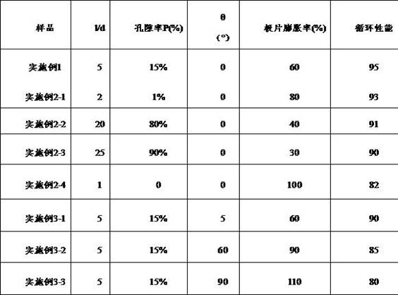
The evaluation results of the negative electrode sheets obtained in the respective examples are shown in table 1. The data results of example 1 and examples 2-1 to 2-4 show that the best performance can be obtained by adjusting the length-diameter ratio and the porosity with appropriate materials and ensuring appropriate specific surface area. The data results of the embodiment 1 and the embodiments 3-1 to 3-3 show that when the growth direction of the negative electrode material is parallel to the horizontal plane of the current collector, the expansion rate of the pole piece is low, the cycle performance of the pole piece is good, and the volume expansion of the pole piece can be reduced by properly adjusting the included angle theta, so that the cycle performance is improved.
Variations and modifications to the above-described embodiments may occur to those skilled in the art, which fall within the scope and spirit of the above description. Therefore, the above description is not intended to limit the invention, the invention is not limited to the specific embodiments disclosed and described above, and modifications and variations such as equivalent substitutions of each raw material and addition of auxiliary components, selection of specific modes, etc., made by those skilled in the art within the substantial scope of the embodiments, should also fall within the protection scope of the claims of the present invention.
Claims (8)
Priority Applications (1)
| Application Number | Priority Date | Filing Date | Title |
|---|---|---|---|
| CN202110093881.6A CN114792809A (en) | 2021-01-25 | 2021-01-25 | Oriented low-expansion negative electrode active material and negative electrode sheet |
Applications Claiming Priority (1)
| Application Number | Priority Date | Filing Date | Title |
|---|---|---|---|
| CN202110093881.6A CN114792809A (en) | 2021-01-25 | 2021-01-25 | Oriented low-expansion negative electrode active material and negative electrode sheet |
Publications (1)
| Publication Number | Publication Date |
|---|---|
| CN114792809A true CN114792809A (en) | 2022-07-26 |
Family
ID=82459891
Family Applications (1)
| Application Number | Title | Priority Date | Filing Date |
|---|---|---|---|
| CN202110093881.6A Pending CN114792809A (en) | 2021-01-25 | 2021-01-25 | Oriented low-expansion negative electrode active material and negative electrode sheet |
Country Status (1)
| Country | Link |
|---|---|
| CN (1) | CN114792809A (en) |
Cited By (2)
| Publication number | Priority date | Publication date | Assignee | Title |
|---|---|---|---|---|
| CN116404148A (en) * | 2023-06-08 | 2023-07-07 | 广汽埃安新能源汽车股份有限公司 | Negative electrode material, negative electrode plate and lithium battery |
| CN117117094A (en) * | 2023-02-15 | 2023-11-24 | 荣耀终端有限公司 | Negative electrode sheet and preparation method thereof, electric cell and battery |
Citations (4)
| Publication number | Priority date | Publication date | Assignee | Title |
|---|---|---|---|---|
| US20110206986A1 (en) * | 2010-02-23 | 2011-08-25 | Samsung Sdi Co., Ltd., | Negative active material for rechargeable lithium battery and rechargeable lithium battery including the same |
| CN108682837A (en) * | 2018-05-17 | 2018-10-19 | 合肥国轩高科动力能源有限公司 | A preparation method of oriented porous silicon material for lithium ion battery |
| CN110350156A (en) * | 2018-04-05 | 2019-10-18 | 三星Sdi株式会社 | Negative electrode active material and lithium rechargeable battery including it |
| CN111628160A (en) * | 2019-02-28 | 2020-09-04 | 三星Sdi株式会社 | Negative active material composite, preparation method thereof, negative electrode and lithium battery |
-
2021
- 2021-01-25 CN CN202110093881.6A patent/CN114792809A/en active Pending
Patent Citations (4)
| Publication number | Priority date | Publication date | Assignee | Title |
|---|---|---|---|---|
| US20110206986A1 (en) * | 2010-02-23 | 2011-08-25 | Samsung Sdi Co., Ltd., | Negative active material for rechargeable lithium battery and rechargeable lithium battery including the same |
| CN110350156A (en) * | 2018-04-05 | 2019-10-18 | 三星Sdi株式会社 | Negative electrode active material and lithium rechargeable battery including it |
| CN108682837A (en) * | 2018-05-17 | 2018-10-19 | 合肥国轩高科动力能源有限公司 | A preparation method of oriented porous silicon material for lithium ion battery |
| CN111628160A (en) * | 2019-02-28 | 2020-09-04 | 三星Sdi株式会社 | Negative active material composite, preparation method thereof, negative electrode and lithium battery |
Cited By (4)
| Publication number | Priority date | Publication date | Assignee | Title |
|---|---|---|---|---|
| CN117117094A (en) * | 2023-02-15 | 2023-11-24 | 荣耀终端有限公司 | Negative electrode sheet and preparation method thereof, electric cell and battery |
| CN117117094B (en) * | 2023-02-15 | 2024-05-17 | 荣耀终端有限公司 | Negative electrode sheet and preparation method thereof, battery cell and battery |
| CN116404148A (en) * | 2023-06-08 | 2023-07-07 | 广汽埃安新能源汽车股份有限公司 | Negative electrode material, negative electrode plate and lithium battery |
| CN116404148B (en) * | 2023-06-08 | 2023-09-05 | 广汽埃安新能源汽车股份有限公司 | Negative electrode material, negative electrode plate and lithium battery |
Similar Documents
| Publication | Publication Date | Title |
|---|---|---|
| JP7254875B2 (en) | Positive electrode active material for lithium secondary battery and lithium secondary battery containing the same | |
| CN111435740B (en) | Positive electrode active material, positive electrode sheet and sodium ion battery | |
| CN113823772B (en) | Silicon-carbon composite material for secondary lithium battery and preparation method thereof | |
| TWI725822B (en) | Lithium battery and anode material thereof | |
| CN107046125B (en) | Composite negative electrode, preparation method thereof and lithium ion battery | |
| CN110233259A (en) | Positive electrode active material, positive electrode plate and electrochemical energy storage device | |
| CN104245624B (en) | Li-La-Ti oxidate sintered body, solid electrolyte containing aforesaid oxides and possess lithium-air battery and the solid lithium battery of aforesaid solid electrolyte | |
| CN109244546B (en) | Solid-state composite electrolyte film and preparation method thereof, and all-solid-state battery | |
| US20150221952A1 (en) | Positive electrode for lithium air battery and lithium air battery including the same | |
| JP2019169354A (en) | Negative electrode for non-aqueous electrolyte secondary battery and non-aqueous electrolyte secondary battery | |
| CN114709367A (en) | Negative plate, lithium ion battery and preparation method of negative plate | |
| JP2021082514A (en) | All-solid battery | |
| TW201942065A (en) | Electrode material for secondary battery and secondary battery | |
| CN119008880A (en) | Positive electrode plate of sodium ion battery and preparation method and application thereof | |
| WO2023108964A1 (en) | Lithium ion battery | |
| CN114792809A (en) | Oriented low-expansion negative electrode active material and negative electrode sheet | |
| CN108736014A (en) | Composite negative pole and preparation method thereof includes the alkali metal battery of composite negative pole | |
| CN115304104B (en) | Manganese series lithium supplementing additive, preparation method and application thereof | |
| CN118800884A (en) | A positive electrode material and its preparation method and application | |
| CN113809285B (en) | Silicon-based composite negative electrode material and preparation method thereof, all-solid lithium battery | |
| CN220527133U (en) | Composite diaphragm, sodium ion battery and electricity utilization device | |
| CN116259747A (en) | A positive electrode material, a secondary battery and an electrical device | |
| CN108539151A (en) | electrode material for secondary battery and secondary battery | |
| CN114649511A (en) | Negative electrode material for nonaqueous electrolyte secondary battery | |
| CN115552662A (en) | Battery and manufacturing method thereof |
Legal Events
| Date | Code | Title | Description |
|---|---|---|---|
| PB01 | Publication | ||
| PB01 | Publication | ||
| SE01 | Entry into force of request for substantive examination | ||
| SE01 | Entry into force of request for substantive examination | ||
| RJ01 | Rejection of invention patent application after publication | ||
| RJ01 | Rejection of invention patent application after publication |
Application publication date: 20220726 |