Disclosure of Invention
The invention mainly aims to provide an instrument board beam and an automobile, and aims to solve the problem that the traditional instrument board beam cannot meet the requirements of light weight and rigidity at the same time.
In order to achieve the above purpose, the invention provides an instrument panel beam for connecting with a vehicle body, the vehicle body including a middle channel, a front wall, a steering column, a left side wall and a right side wall, the instrument panel beam is characterized in that the instrument panel beam includes a main beam, a support frame, a left end plate, a right end plate and a connecting frame, the main beam includes a metal framework and a plastic part, the metal framework extends along a first direction, the left end plate and the right end plate are respectively located at two ends of the metal framework, the plastic part is coated at one side of the metal framework, the plastic part, the left end plate, the right end plate and the support frame are integrally injection-molded by using the metal framework as an insert, the support frame extends along a second direction, the second direction is mutually perpendicular to the first direction, the support frame is used for connecting with the middle channel, and the connecting frame is connected with the plastic part, the link be used for with before enclose with steering column connects, the left end board be used for with the left side encloses to be connected, the right end board be used for with the right side encloses to be connected.
Optionally, one side of the metal framework, which is far away from the plastic part, is provided with a mounting groove along the first direction in a penetrating manner, and a plurality of reinforcing ribs are formed in the mounting groove in an integrated injection molding manner.
Optionally, a plurality of through-holes have been seted up to metal framework, and is a plurality of the through-hole with a plurality of the strengthening rib one-to-one sets up, metal framework is formed with towards keeping away from the convex linkage segment of direction of preceding wall, the support frame set up in on the linkage segment.
Optionally, the connecting frame comprises a first bracket and a second bracket which are connected, the first bracket is used for being connected with the plastic part and the steering column, the second bracket is used for being connected with the front wall, and the second bracket is formed with a crumple structure.
Optionally, the first bracket includes a first connecting plate and two connecting arms, the first connecting plate is connected with the plastic part through a fastener, the two connecting arms are all used for being connected with the steering column, each connecting arm includes a first connecting portion, a second connecting portion and a third connecting portion that are connected, the first connecting plate is connected between the two first connecting portions, the second connecting portion is connected with the plastic part, and the third connecting portion is connected with the second bracket.
Optionally, the second support including the second connecting plate that is connected with the structure of collapsing, the second connecting plate is connected in two between the third connecting portion, the structure of collapsing is including the first portion of collapsing and the second portion of collapsing that contracts that are connected and be the contained angle setting, first portion of collapsing be used for with before enclose and be connected, the second portion of collapsing with the second connecting plate is connected.
Optionally, the crumple structure further includes a third crumple portion, two adjacent sides of the third crumple portion are respectively connected with the second crumple portion and the first crumple portion, the first crumple portion is formed with a positioning groove, the third crumple portion is formed with a positioning protrusion in plug-in fit with the positioning groove, and the third crumple portion is provided with a guide groove.
Optionally, the support frame includes a first support bar, a second support bar and a plurality of reinforcing bars, the first support bar and the second support bar extend along the second direction, and the plurality of reinforcing bars are connected between the first support bar and the second support bar.
Optionally, the instrument panel cross beam further comprises a plurality of mounting brackets, the plurality of mounting brackets are arranged on the main beam and/or the support frame at intervals, and each mounting bracket is used for being connected with a vehicle body structure; and/or the presence of a gas in the gas,
the instrument board beam further comprises a fixing frame, the fixing frame is connected with the plastic part, a plurality of fixing bulges are arranged on the fixing frame, and the fixing bulges are used for being connected with a vehicle body structure.
In addition, the invention also provides an automobile which comprises the automobile body and the instrument board cross beam.
In the technical scheme of the invention, the metal framework mainly plays roles of supporting shaping and bearing force, and can greatly improve the front collision and side collision performance of the instrument board beam. Working of plastics, left end board, right side board and support frame use metal framework as the integrative injection moulding of inserts, have improved the manufacturing efficiency of instrument board crossbeam. The support frame extends along the up-and-down direction, and the support frame is used for being connected with the middle channel, so that the instrument board beam is connected with the middle channel. The link is used for enclosing before with and steering column is connected to realize that the instrument board crossbeam encloses before with steering column is connected. The left end plate is used for being connected with the left side wall, so that the instrument board beam is connected with the left side wall. The right end plate is used for being connected with the right side wall, so that the instrument board beam is connected with the right side wall. The instrument board beam is supported and stressed by the metal framework, the rigidity requirement of the instrument board beam is met, the front collision and side collision performance of the instrument board beam is greatly improved, and the safety performance of the instrument board beam is improved. And working of plastics, left end board, right side board and support frame use metal framework as integrative injection moulding of inserts, have alleviateed the weight of instrument board crossbeam, have satisfied the lightweight requirement of instrument board crossbeam.
Detailed Description
The technical solutions in the embodiments of the present invention will be clearly and completely described below with reference to the drawings in the embodiments of the present invention, and it is obvious that the described embodiments are only a part of the embodiments of the present invention, and not all of the embodiments. All other embodiments, which can be derived by a person skilled in the art from the embodiments given herein without making any creative effort, shall fall within the protection scope of the present invention.
It should be noted that all the directional indicators (such as up, down, left, right, front, and rear … …) in the embodiment of the present invention are only used to explain the relative position relationship between the components, the movement situation, etc. in a specific posture (as shown in the drawing), and if the specific posture is changed, the directional indicator is changed accordingly.
In addition, the descriptions related to "first", "second", etc. in the present invention are only for descriptive purposes and are not to be construed as indicating or implying relative importance or implicitly indicating the number of technical features indicated. Thus, a feature defined as "first" or "second" may explicitly or implicitly include at least one such feature. In the description of the present invention, "a plurality" means at least two, e.g., two, three, etc., unless specifically limited otherwise.
In the present invention, unless otherwise expressly stated or limited, the terms "connected," "secured," and the like are to be construed broadly, and for example, "secured" may be a fixed connection, a removable connection, or an integral part; can be mechanically or electrically connected; they may be directly connected or indirectly connected through intervening media, or they may be connected internally or in any other suitable relationship, unless expressly stated otherwise. The specific meanings of the above terms in the present invention can be understood by those skilled in the art according to specific situations.
In addition, the technical solutions in the embodiments of the present invention may be combined with each other, but it must be based on the realization of those skilled in the art, and when the technical solutions are contradictory or cannot be realized, such a combination of technical solutions should not be considered to exist, and is not within the protection scope of the present invention.
The description of the orientations of "up", "down", "front", "rear", "left", "right", etc. in the present invention, with reference to the orientation shown in fig. 1, is merely for explaining the relative positional relationship between the respective components in the attitude shown in fig. 1, and if the particular attitude is changed, the directional indication is changed accordingly.
The invention provides an instrument panel cross member.
In one embodiment, as shown in fig. 1 to 4, the dashboard cross beam 100 is configured to be connected to a vehicle body, the vehicle body includes a center channel, a front panel, a steering column, a left side wall and a right side wall, the dashboard cross beam 100 includes a main beam 10, a support frame 20, a left end panel 30, a right end panel 40 and a connecting frame 50, the main beam 10 includes a metal framework 11 and a plastic member 12, the metal framework 11 extends along a first direction, the left end panel 30 and the right end panel 40 are respectively located at two ends of the metal framework 11, the plastic member 12 is coated on one side of the metal framework 11, the plastic member 12, the left end panel 30, the right end panel 40 and the support frame 20 are integrally injection-molded by using the metal framework 11 as an insert, the support frame 20 extends along a second direction, the second direction is perpendicular to the first direction, the support frame 20 is configured to be connected to the center channel, the connecting frame 50 is connected to the plastic member 12, the connecting frame 50 is configured to be connected to the front panel and the steering column, the left side wall 30 is configured to be connected to the left side wall, the right end panel 40 is adapted to be connected to the right skirt.
The first direction is the left-right direction in fig. 1, and the second direction is the up-down direction in fig. 1.
Referring to fig. 1, the metal framework 11 extends in the left-right direction, the left end plate 30 is located at the left end of the metal framework 11, the right end plate 40 is located at the right end of the metal framework 11, the plastic member 12 is coated on the front side of the metal framework 11, the metal framework 11 mainly plays a role in supporting, shaping and bearing, and the metal framework 11 can greatly improve the frontal impact and side impact performance of the instrument panel beam 100. The plastic part 12, the left end plate 30, the right end plate 40 and the support frame 20 are integrally injection-molded by taking the metal framework 11 as an insert, so that the manufacturing efficiency of the instrument panel beam 100 is improved. The support bracket 20 extends in the up-down direction, and the support bracket 20 is used for connecting with the center tunnel, thereby realizing the connection of the instrument panel cross member 100 with the center tunnel. The connecting frame 50 is used to connect the cowl and the steering column, thereby connecting the dash cross member 100 to the cowl and the steering column. The left end plate 30 is used to connect with the left side wall, thereby connecting the instrument panel cross member 100 with the left side wall. The right end plate 40 is used to connect with the right side wall, thereby connecting the instrument panel cross member 100 with the right side wall.
In the embodiment, the metal framework 11 is used for supporting and bearing, so that the rigidity requirement of the instrument panel beam 100 is met, the frontal impact and side impact performances of the instrument panel beam 100 are greatly improved, and the safety performance of the instrument panel beam 100 is improved. In addition, the plastic part 12, the left end plate 30, the right end plate 40 and the support frame 20 are integrally injection-molded by taking the metal framework 11 as an insert, so that the weight of the instrument panel beam 100 is reduced, and the requirement of light weight of the instrument panel beam 100 is met.
The metal framework 11 can be made of automobile structural steel, aluminum alloy, magnesium alloy and the like, and the forming process can be conventional metal forming processes such as stamping, welding, die casting and the like so as to reduce the product cost to the maximum extent. The thickness of the metal skeleton 11 depends on the material used, and is generally 1mm to 3 mm. In order to ensure the tight combination between the metal framework 11 and the injection molded body, the surface of the metal framework 11 is treated by one or a combination of sand blasting, chemical corrosion, anodic oxidation, laser processing and gluing, and the anodic oxidation process of acid solution is preferably adopted. Based on the performance and formability requirements of the product, the injection molding material can be one of PP +60GF, PA6+60GF, PA66+60GF, PA +30CF and PA +40 CF.
In an embodiment, a mounting groove 111 is formed in the metal framework 11 at a side away from the plastic part 12 along the first direction, and a plurality of reinforcing ribs 13 are integrally formed in the mounting groove 111 by injection molding.
Referring to fig. 1 and 3, a mounting groove 111 is formed in the rear side of the metal framework 11 in a left-right direction, a plurality of reinforcing ribs 13 are integrally injection-molded in the mounting groove 111, and the reinforcing ribs 13 are arranged to enhance the structural stability of the instrument panel beam 100 and improve the safety performance of the instrument panel beam 100. Moreover, the installation groove 111 is formed to reduce the weight of the metal framework 11, so that the instrument panel beam 100 is further reduced in weight.
In an embodiment, the metal frame 11 is provided with a plurality of through holes 112, the plurality of through holes 112 and the plurality of reinforcing ribs 13 are disposed in a one-to-one correspondence, the metal frame 11 is formed with a connecting section 113 protruding in a direction away from the front wall, and the supporting frame 20 is disposed on the connecting section 113.
Referring to fig. 1 to 3, a plurality of through holes 112 are provided to enable the injection molded body to penetrate through the front and rear sides of the metal framework 11 during injection molding, the reinforcing ribs 13 are formed on the rear side of the metal framework 11, and the plastic part 12 and the reinforcing ribs 13 clamp the metal framework 11 in tandem, thereby improving the structural strength of the instrument panel beam 100. Specifically, the thickness of the rubber of the reinforcing ribs 13 is 1.5-2.5 mm, and the layout of the reinforcing ribs 13 follows the principle that the density of the reinforcing ribs gradually changes from the driving side to the copilot side, so that the weight of the product is reduced on the premise of ensuring the maximum performance.
In a preferred technical scheme, cladding ribs 14 are formed on the plastic part 12, the space between the cladding ribs 14 is related to the position of the reinforcing rib 13, and the cladding ribs 14 are arranged to enable the structural strength of the instrument panel beam 100 to be higher and improve the safety performance of the instrument panel beam 100.
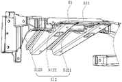
In one embodiment, the connecting bracket 50 includes a first bracket 51 and a second bracket 52 connected, the first bracket 51 is used for connecting with the plastic member 12 and the steering column, the second bracket 52 is used for connecting with the front wall, and the second bracket 52 is formed with a crush structure 522.
Referring to fig. 1 and 2, the connecting frame 50 may be made of structural steel, aluminum alloy, magnesium alloy, or the like, and the forming process may be sheet metal welding or die casting, which is recommended in terms of cost and performance. The first bracket 51 is used for connection with a steering column, thereby realizing the link bracket 50 for connection with a steering column. The second bracket 52 is used for connection with the cowl, thereby realizing the connecting bracket 50 for connection with the cowl. The first bracket 51 is connected to the plastic member 12, thereby connecting the connecting bracket 50 to the plastic member 12. The second bracket 52 is formed with a crush structure 522 to ensure that the second bracket 52 absorbs impact force to collapse after receiving a forward collision force from the front wall of the vehicle body, thereby protecting the safety of the passenger.
In one embodiment, the first bracket 51 includes a first connection plate 511 and two connection arms 512, the first connection plate 511 is connected to the plastic member 12 by a fastener, the two connection arms 512 are used for connecting to a steering column, each connection arm 512 includes a first connection portion 5121, a second connection portion 5122 and a third connection portion 5123, the first connection plate 511 is connected between the two first connection portions 5121, the second connection portion 5122 is connected to the plastic member 12, and the third connection portion 5123 is connected to the second bracket 52.
Referring to fig. 1, 2 and 4, the fastening member may be a general bolt or an FDS screw, and the first connection plate 511 is mounted on the plastic member 12 through the fastening member, so that the connection between the first bracket 51 and the plastic member 12 is stable and reliable, and the structural stability of the instrument panel cross member 100 is improved. Both attachment arms 512 are used to attach to the steering column, thereby enabling the attachment frame 50 to be used to attach to the steering column. The first connection plate 511 is connected between the two first connection portions 5121, which improves the structural strength of the first bracket 51. The second connecting portion 5122 is connected to the plastic part 12, and the shape of the second connecting portion 5122 matches with that of the plastic part 12, so that the first bracket 51 is more tightly and reliably connected to the plastic part 12. The third connecting portion 5123 is connected to the second bracket 52, so that the first bracket 51 is connected to the second bracket 52.
In an embodiment, the second bracket 52 includes a second connecting plate 521 and a crush structure 522 connected to each other, the second connecting plate 521 is connected between two third connecting portions 5123, the crush structure 522 includes a first crush portion 5221 and a second crush portion 5222 connected to each other and disposed at an included angle, the first crush portion 5221 is used for being connected to the front wall, and the second crush portion 5222 is connected to the second connecting plate 521.
Referring to fig. 1, 2 and 4, the second connecting plate 521 is connected between the two third connecting portions 5123, so that the second bracket 52 is connected to the first bracket 51, and the structural stability of the connecting bracket 50 is improved. The first and second crush portions 5221 and 5222 are disposed at an included angle, so that the crush structure 522 has better performance and protects the safety of the passengers. The first crush portion 5221 is used to connect with the cowl, thereby realizing that the connecting bracket 50 is used to connect with the cowl. The second crush portion 5222 is connected to the second web 521, thereby achieving the connection of the crush structure 522 to the second web 521.
In an embodiment, the crush structure 522 further includes a third crush portion 5223, two adjacent sides of the third crush portion 5223 are respectively connected to the second crush portion 5222 and the first crush portion 5221, the first crush portion 5221 is formed with a positioning groove 5224, the third crush portion 5223 is formed with a positioning protrusion 5225 inserted into the positioning groove 5224, and the third crush portion 5223 is formed with a guiding groove 5226.
Referring to fig. 1, 2 and 4, the right side of the third crush portion 5223 is connected to the second crush portion 5222, the rear side of the third crush portion 5223 is connected to the first crush portion 5221, and the first crush portion 5221, the second crush portion 5222 and the third crush portion 5223 form a stable frame structure, so that the performance of the crush structure 522 is better, and the second bracket 52 can absorb the impact force from the front of the vehicle body to collapse, thereby protecting the safety of the passengers. The third crush portion 5223 and the first crush portion 5221 can be connected by welding, which makes the crush structure 522 stronger. A positioning protrusion 5225 is formed at the rear end of the third crush portion 5223, and the positioning protrusion 5225 and the positioning groove 5224 are matched to connect the third crush portion 5223 and the first crush portion 5221 to play a positioning role, so that the third crush portion 5223 and the first crush portion 5221 can be conveniently welded. The third crumple section 5223 is provided with a guide groove 5226, so that the crumple structure 522 is better in performance by further guiding the crumple through reducing materials, and the safety performance of the instrument panel beam 100 is improved.
Referring to fig. 2, the left crush structure 522 includes only the first crush portion 5221 and the second crush portion 5222, and the right crush structure 522 includes the first crush portion 5221, the second crush portion 5222 and the third crush portion 5223, and only one of the two crush structures may be installed according to actual needs, or both of the two crush structures may be installed at the same time.
In one embodiment, the support frame 20 includes a first support bar 21, a second support bar 22, and a plurality of reinforcement bars 23, the first support bar 21 and the second support bar 22 extending along the second direction, the plurality of reinforcement bars 23 being connected between the first support bar 21 and the second support bar 22.
Referring to fig. 1, the first support bar 21 and the second support bar 22 extend in the vertical direction and are connected to the middle portion of the plastic member 12. The center tunnel includes a left center tunnel and a right center tunnel, the first support bar 21 is used to be connected with the left center tunnel of the vehicle body, and the second support bar 22 is used to be connected with the right center tunnel of the vehicle body, thereby implementing the support bracket 20 for being connected with the center tunnel. A plurality of reinforcing rods 23 are connected between the first support rod 21 and the second support rod 22, so that the structural stability of the support frame 20 is enhanced, and the structural strength of the instrument panel beam 100 is improved.
In one embodiment, referring to fig. 1, the instrument panel cross member 100 further includes a plurality of mounting brackets 60, the plurality of mounting brackets 60 are disposed on the main beam 10 and/or the support frame 20 at intervals, and each mounting bracket 60 is used for connecting with the vehicle body structure. The mounting bracket 60 is arranged to facilitate connection of the instrument panel cross beam 100 and a vehicle body structure, for example, vehicle body structures such as an air conditioner and an air bag, so that the instrument panel cross beam 100 is convenient to use, and the mounting bracket 60 is integrally injection-molded on the metal framework 11.
In one embodiment, the instrument panel cross beam 100 further includes a fixing frame 70, the fixing frame 70 is connected with the plastic part 12, a plurality of fixing protrusions 71 are disposed on the fixing frame 70, and the fixing protrusions 71 are used for being connected with a vehicle body structure. Referring to fig. 1, the fixing frame 70 is disposed to enhance the structural stability of the instrument panel cross member 100, and the fixing protrusions 71 on the fixing frame 70 facilitate the connection between the instrument panel cross member 100 and a vehicle body structure, such as a vehicle body structure of an instrument panel, a display, and the like, and facilitate the use of the instrument panel cross member 100, and the fixing brackets are integrally injection-molded on the metal framework 11.
In the preferred technical scheme, left end plate 30 and right end plate 40 have a screw hole through the integrated into one piece that moulds plastics, and threaded hole installs the bush, and the bolt is conveniently installed, and left end plate 30 encloses through the bolt and is connected with the left side, and right end plate 40 encloses through the bolt and is connected with the right side.
In addition, the invention also provides an automobile which comprises a vehicle body and the instrument panel cross beam 100. The specific structure of the instrument panel beam 100 refers to the above embodiments, and since the automobile adopts all technical solutions of the above embodiments, at least all beneficial effects brought by the technical solutions of the above embodiments are achieved, and are not repeated herein.
The above description is only a preferred embodiment of the present invention, and not intended to limit the scope of the present invention, and all modifications and equivalents of the present invention, which are made by the contents of the present specification and the accompanying drawings, or directly/indirectly applied to other related technical fields, are included in the scope of the present invention.