Disclosure of Invention
In view of the above, embodiments of the present application are intended to provide a protection device for a vehicle engine, a control method, a computer device and a vehicle, which solve the problem of icing when a crankcase ventilation system is operated in a low-temperature environment.
In order to achieve the above purpose, the technical solution of the embodiment of the present application is implemented as follows:
in one aspect of the present application, there is provided a protection device for a vehicle engine, including:
the air inlet system is connected with an air inlet manifold of the engine and used for inputting outside air;
a ventilation system connecting a crankcase of the engine and the intake system for regulating a gas pressure in the crankcase;
the exhaust gas recirculation system is connected with an air outlet pipe of the engine and the air inlet system, a connection point of the exhaust gas recirculation system and the air inlet system is located at the upstream of a connection point of the ventilation system and the air inlet system, and the exhaust gas recirculation system comprises an exhaust gas recirculation valve and is used for controlling the exhaust gas recirculation system to be communicated with the air inlet system.
Furthermore, the air inlet system comprises an air inlet pipeline, a supercharger and an intercooler, the air inlet pipeline is connected with the air inlet manifold, a pressure shell end of the supercharger and the intercooler are sequentially arranged on the air inlet pipeline along the air flowing direction, and a volute end of the supercharger is arranged on the exhaust gas recirculation system;
the ventilation system comprises a high-load pipeline, a low-load pipeline and a one-way valve, wherein a connecting point of the high-load pipeline and the air inlet pipeline is positioned at the upstream of the supercharger, a connecting point of the low-load pipeline and the air inlet pipeline is positioned on the air inlet manifold, and a connecting point of the exhaust gas recirculation system and the air inlet pipeline is positioned at the upstream of a connecting point of the high-load pipeline and the air inlet pipeline;
the high-load pipeline and the low-load pipeline are both provided with the check valves, and the check valves are used for enabling gas in the crankcase to flow into the intake manifold along the high-load pipeline or the low-load pipeline in a one-way mode.
Further, the air intake system further comprises an air filter and a mixing valve which are sequentially arranged on the air intake pipeline along the gas flowing direction, and the connection point of the exhaust gas recirculation system and the air intake system is positioned at the downstream of the mixing valve.
Further, the exhaust gas recirculation system further includes:
the exhaust pipeline is connected with an exhaust pipe of the engine and used for exhausting the exhaust gas in the engine;
and the circulating pipeline is communicated with the exhaust pipeline and the air inlet system and is used for discharging at least part of exhaust gas into the air inlet system, the exhaust gas recirculation valve is arranged on the circulating pipeline, and the connection point of the circulating pipeline and the air inlet system is positioned upstream of the connection point of the ventilation system and the air inlet system.
Further, the exhaust gas recirculation system further includes:
the three-way catalyst is arranged on the exhaust pipeline and used for purifying the exhausted exhaust gas, and the connecting point of the circulating pipeline communicated with the exhaust pipeline is positioned at the downstream of the three-way catalyst;
and the cooler is arranged on the circulating pipeline and used for cooling the exhaust gas and then feeding the cooled exhaust gas into the air intake system.
In a second aspect of the present application, there is provided a control method of a vehicle engine, comprising:
acquiring an ambient temperature;
acquiring the rotating speed and the torque of the engine;
controlling an opening of an exhaust gas recirculation valve based on the ambient temperature and a speed and torque of the engine.
Further, the step of controlling the opening of the exhaust gas recirculation valve based on the ambient temperature and the rotational speed and torque of the engine specifically comprises:
and if the ambient temperature is less than or equal to a first threshold value, the rotating speed of the engine is greater than a second threshold value, the torque of the engine is greater than a third threshold value, and the opening degree of the exhaust gas recirculation valve is increased.
Further, the control method further includes:
acquiring the temperature of cooling liquid of a cooling system;
acquiring the outlet air temperature of a cooler of the exhaust gas recirculation system;
and if the ambient temperature is less than or equal to a first threshold value, the rotating speed of the engine is greater than a second threshold value, the torque of the engine is greater than a third threshold value, the temperature of the outlet air flowing through the cooler is less than or equal to a fourth threshold value, and the rotating speed of an electric water pump of the cooling system is reduced and/or the opening degree of an electronic thermostat is reduced.
In a third aspect of the application, a computer device is provided, comprising one or more processing modules configured to execute computer instructions stored in a memory module to perform the control method described above.
In a fourth aspect of the present application, there is provided a vehicle including the above-described protection apparatus; and/or the computer device described above.
The protection device of vehicle engine that this application embodiment provided, air intake system and engine air intake manifold are connected, and crankcase and the air intake system of engine are connected to ventilation system, and exhaust gas recirculation system connects the outlet duct and the air intake system of engine, and exhaust gas recirculation system and air intake system's tie point are located the upper reaches of ventilation system and air intake system's tie point. This application is located ventilation system's upper reaches through the tie point that sets up exhaust gas recirculation system and air intake system, and control exhaust gas recirculation valve makes exhaust gas recirculation system and air intake system be connected, and control exhaust gas recirculation gas flow makes exhaust gas recirculation system's waste gas heat heating air intake system's outside air, and then promotes the gas temperature, has reduced the phenomenon of freezing of ventilation system and air intake system's tie point.
Detailed Description
It should be noted that, in the present application, technical features in examples and embodiments may be combined with each other without conflict, and the detailed description in the specific embodiment should be understood as an explanation of the gist of the present application and should not be construed as an improper limitation to the present application.
The present application will be described in further detail with reference to the following drawings and specific embodiments. The descriptions of "first," "second," etc. in the embodiments of the present application are for descriptive purposes only and are not to be construed as indicating or implying relative importance or implicitly including at least one feature. In the description of the embodiments of the present application, "a plurality" means at least two, e.g., two, three, etc., unless specifically limited otherwise.
In order to meet the increasingly stringent requirements of automotive emissions regulations, currently gasoline engines are generally provided with crankcase ventilation systems to reintroduce incompletely combusted fuel vapors in the crankcase into the intake manifold and return the incompletely combusted fuel vapors to the combustion chamber for combustion, thereby achieving the purposes of reducing the emissions of crankcase pollutants and providing engine economy. The crankcase ventilation system generally has two branches, wherein when one branch is in low rotating speed and small load, the mixed gas in the crankcase directly enters an air inlet manifold from the crankcase; the other branch is that the mixed gas enters an air inlet pipeline after air filtration and before a supercharger compressor from a crankcase during high rotating speed and large load, and is pressurized together with fresh air to enter an air inlet manifold to participate in combustion.
In a low-temperature or extremely cold area in winter, when an engine works at a high rotating speed and a large load, high-temperature mixed gas in a crankcase ventilation pipe meets cold air in an air filtering air pipe of a ventilation system, and the mixed gas freezes and accumulates at the joint of pipelines until the pipelines are completely blocked, so that the pressure in the crankcase of the engine rises. The pressure of the crankcase rises, which causes the front and the rear oil seals of the crankshaft to deflect and even fall off, and the engine leaks engine oil and damages the engine. And the ice blocks in the air inlet pipeline enter the supercharger pressure shell, so that the risk of damaging the supercharger impeller is caused. In the related art, the problems of increased cost, difficult arrangement or non-ideal anti-icing effect exist in the scheme of adding an electric heating device or adding an electric control proportional valve in a crankcase ventilation system or adopting a scheme of wrapping a heat insulation material and a high-temperature water path.
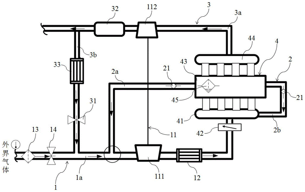
In view of the above, in a first aspect of the embodiments of the present application, please refer to fig. 1, a protection device for a vehicle engine 4 is provided, which includes an air intake system 1, a ventilation system 2 and an exhaust gas recirculation system 3.
The intake system 1 is connected to an intake manifold 41 of the engine 4 for inputting outside air, such as fresh air. The ventilation system 2 connects the crankcase 43 of the engine 4 and the intake system 1 for regulating the gas pressure in the crankcase 43. It will be appreciated that during operation of the engine 4, high pressure combustible mixture and burnt gas from the combustion chambers may leak into the crankcase 43, more or less through the gap between the piston group and the cylinder, causing blow-by gases. The blow-by gas is composed of unburned fuel gas, water vapor, exhaust gas and the like, which can dilute engine oil, reduce the service performance of the engine oil and accelerate the oxidation and deterioration of the engine oil. The water and the air are condensed in the engine oil to form oil sludge and block an oil way; acid gases in the exhaust gas are mixed into the lubrication system, which can cause corrosion and accelerated wear of the engine 4 parts; blow-by also causes the crankcase 43 to be under excessive pressure and thus breaks the seal of the crankcase 43, allowing oil to leak and run off. Ventilation of the crankcase 43 must be performed in order to prevent excessive crankcase 43 pressure, extend engine oil life, reduce wear and corrosion of parts, and prevent oil leakage from the engine 4.
The exhaust gas recirculation system 3 connects the outlet pipe 44 of the engine 4 with the air intake system 1, the connection point of the exhaust gas recirculation system 3 and the air intake system 1 is located upstream of the connection point of the ventilation system 2 and the air intake system 1, and the exhaust gas recirculation system 3 includes an exhaust gas recirculation valve 31 for controlling the exhaust gas recirculation system 3 to be capable of communicating with the air intake system 1 and controlling the flow rate. Exhaust Gas recirculation, or Exhaust Gas Return, EGR for short. An exhaust gas recirculation system is called an EGR system for short, and an exhaust gas recirculation valve is called an EGR valve for short.
The protection device that this application embodiment provided sets up exhaust gas recirculation system 3 and air intake system 1's tie point and is located the upstream of ventilation system 2 and air intake system 1's tie point, and control exhaust gas recirculation valve 31 makes exhaust gas recirculation system 3 be connected with air intake system 1, makes exhaust gas recirculation system 3's waste gas heat heating air intake system 1's outside air, has reduced ventilation system 2's icing phenomenon, and the effect is obvious, arranges simply, has practiced thrift the cost.
In one embodiment, the intake system 1 includes an intake pipe 1a, a supercharger 11, and a intercooler 12, the intake pipe 1a is connected to the intake manifold 41 for inputting the external air, a pressure shell end of the supercharger 11 and the intercooler 12 are sequentially disposed on the intake pipe 1a in the gas flowing direction, and a supercharger scroll end 112 is disposed on the exhaust gas recirculation system 3. The turbocharger volute end 112 pushes turbine blades to rotate through exhaust gas discharged by the exhaust gas recirculation system 3, the turbine blades drive blades of the turbocharger volute end 111 through bearings to compress and accelerate gas for increasing the pressure of the gas, and the intercooler 12 is used for reducing the temperature of the pressurized high-temperature air so as to reduce the heat load of the engine 4 and improve the air inflow, and further increase the power of the engine 4.
The ventilation system 2 comprises a high-load line 2a, a low-load line 2b and a non-return valve 21. The connection point of the high-load line 2a to the intake line 1a is located upstream of the supercharger 11, the connection point of the low-load line 2b to the intake line 1a is located on the intake manifold 41, and the connection point of the exhaust gas recirculation system 3 to the intake line 1a is located upstream of the connection point of the high-load line 2a to the intake line 1 a. A check valve 21 is provided on each of the high load line 2a and the low load line 2b for one-way flow of gas in the crankcase 43 along the high load line 2a or along the low load line 2b to the intake manifold 41.
Specifically, a throttle valve 42 is provided between the intake manifold 41 and the intercooler 12. When the engine 4 is in a low-load condition, the throttle valve 42 is close to closing, the negative pressure of the intake manifold 41 is larger, for example, minus 40 to minus 70kPa, and the negative pressure behind the air filter 13 is about minus 3kPa, at this time, the exhaust gas generated by piston leakage in the crankcase 43 of the engine 4 rises and passes through the oil-gas separator 45 to separate oil and water, the separated gas is pumped into the intake manifold through the low-load pipeline 2b and finally enters the combustion chamber to be burnt, and the gas in the intake pipeline 1a cannot be pumped into the intake manifold 41 through the high-load pipeline 2a reversely due to the one-way valve 21 arranged on the high-load pipeline 2 a. When the engine 4 is in a high-load working condition, the opening degree of the throttle valve 42 is large, and the supercharger 11 supercharges the intake pressure, so that the pressure in the intake manifold 41 is high, and the gas separated by the gas-oil separator 45 in the crankcase 43 cannot be extracted through the low-load pipeline 2 b. At this time, the negative pressure of the gas in front of the pressure shell end 111 of the supercharger is about-3 kPa, the gas is pumped to the front of the pressure shell end 111 of the supercharger through the high-load pipeline 2a, the gas mixed with the outside air enters the pressure shell end 111 of the supercharger under the action of pressure difference for supercharging, and then the gas is cooled by the intercooler 12 and enters the intake manifold 41, and finally the gas enters the combustion chamber for burning.
In one embodiment, the intake system 1 further comprises an air cleaner 13 and a mixing valve 14, which are arranged in this order in the intake line 1a in the direction of gas flow, and the connection point of the exhaust gas recirculation system 3 to the intake system 1 is located downstream of the mixing valve 14. The air cleaner 13 is used for filtering the outside air and absorbing the particulate matters. The mixing valve 14 is used for adjusting the mixing ratio of the external air and the exhaust gas, changing the gas pressure upstream and downstream of the mixing valve 14, generating a pressure difference, and enabling the external air to flow to the intake manifold 41 in a one-way mode after being filtered by the air filter 13.
In one embodiment, the exhaust gas recirculation system 3 comprises an exhaust line 3a, a recirculation line 3b and an exhaust gas recirculation valve 31. The exhaust line 3a is connected to an outlet pipe 44 of the engine 4 for discharging exhaust gas from the engine 4. It will be appreciated that exhaust from the engine 4 is discharged via the exhaust line 3a into the vehicle exhaust system and thence into the atmosphere. The circulating pipeline 3b is communicated with the exhaust pipeline 3a and the air inlet system 1, the connecting point of the circulating pipeline 3b and the air inlet pipeline 1a is located at the upstream of the connecting point of the high-load pipeline 2a and the air inlet pipeline 1a and is used for discharging at least part of exhaust gas into the air inlet system 1, and the exhaust gas recirculation valve 31 is arranged on the circulating pipeline 3b and controls the exhaust gas to enter the air inlet system 1 through the circulating pipeline 3 b. It is understood that the exhaust gas recirculation valve 31 controls the opening and closing and the opening by an on-board controller, and thus controls the amount of exhaust gas recirculation.
In one embodiment, the exhaust gas recirculation system 3 further includes a three-way catalyst 32 and a cooler 33, the three-way catalyst 32 is provided on the exhaust line 3a for purifying the exhaust gas, and a connection point of the circulation line 3b to the exhaust line 3a is located downstream of the three-way catalyst 32. The three-way catalyst can convert harmful gases such as CO, HC and NOx discharged by automobile exhaust into harmless carbon dioxide, water and nitrogen through oxidation and reduction. Meanwhile, the three-way catalyst 32 can also absorb particulate matters in the exhaust gas, and reduce the particulate matters discharged into the atmosphere or entering the circulating pipeline 3b to block the air intake system 1. A cooler 33 is provided on the circulation line 3b for cooling the exhaust gas before it enters the intake system 1. It can be understood that the high temperature exhaust gas needs to be cooled by the cooler 33 and then flows into the air intake system 1, in a low temperature or extremely cold environment, the temperature of the cooled exhaust gas is still higher than the external gas input into the air intake system 1, when the engine 4 is in a high load condition, blow-by gas generated by combustion in the combustion chamber of the crankcase 43 is discharged to the air intake system 1 through the high load pipeline 2a, the temperature of the external gas in the air intake pipeline 1a is increased by the exhaust gas, and then the exhaust gas is intersected with the mixed gas of the crankcase 43 with high water vapor content in the high load pipeline 2a of the ventilation system 2, so that the possibility of freezing of the water vapor at the intersection and nearby is reduced, and the phenomenon that the sectional area of the pipeline is reduced or even the pipe orifice is blocked due to freezing is reduced.
Specifically, in a low-temperature or extremely cold environment, when the engine 4 is in a high-load working condition, the exhaust gas recirculation valve 31 is opened, the external gas flows into the intake pipeline 1a, the blowby gas generated during combustion of the combustion chamber of the crankcase 43 is discharged to the intake system 1 through the high-load pipeline 2a, flows into the intake pipeline 1a, the high-temperature exhaust gas of the crankcase 43 enters the exhaust pipeline 3a through the exhaust pipe, after being subjected to catalytic treatment by the three-way catalyst 32, a part of the high-temperature exhaust gas is cooled by the cooler 33 and then discharged to the intake system 1 through the exhaust gas recirculation valve 31, and is intersected with the external gas flowing through the air filter 13 and the mixing valve 14 in sequence, the temperature of the external gas is increased after the intersection of the high-temperature exhaust gas and the external gas, and then the blowby gas generated during combustion of the combustion chamber of the crankcase 43 is intersected with the mixed gas, so that the phenomenon that the sectional area of the pipeline is reduced due to icing or even the pipe orifice is blocked at the intersection is reduced. It will be appreciated that the connection point of the high-load line 2a to the inlet line 1a is located downstream of the connection point of the recirculation line 3b to the inlet line 1 a. Finally, the gas is pressurized by the supercharger shell pressing end 111 and cooled by the intercooler 12 and is discharged to the intake manifold 41, and then enters the combustion chamber of the crankcase 43 for combustion.
In a second aspect of the embodiment of the present application, please refer to fig. 2, which provides a control method for a vehicle engine 4, comprising:
s1, acquiring the ambient temperature;
s2, acquiring the rotating speed and the torque of the engine;
and S3, controlling the opening degree of the exhaust gas recirculation valve based on the ambient temperature and the rotating speed and the torque of the engine.
The control method provided by the embodiment of the application is applied to any one of the protection devices, and the opening degree of the exhaust gas recirculation valve 31 is controlled based on the ambient temperature and the rotating speed and the torque of the engine 4, so that the exhaust gas recirculation system 3 supplies exhaust gas to the air intake system 1, the low-temperature air of the air intake pipeline 1a is heated by using the heat of the exhaust gas, the temperature of the mixed gas in the air intake pipeline 1a is increased, the temperature of the mixed gas in the air intake pipeline 1a is higher than the freezing temperature of the water vapor of the ventilation system 2 of the crankcase 43, and the phenomenon that the ventilation system 2 of the crankcase 43 is frozen is reduced.
The control method according to the embodiment of the present application will be described in detail with reference to specific embodiments.
And S1, acquiring the ambient temperature.
In this step, the manner of obtaining the ambient temperature is not limited, and the ambient temperature may be obtained by the temperature sensor and sent to the onboard controller, or the onboard controller may be connected to the network to obtain the local ambient temperature. The vehicle-mounted controller is also called a traveling computer, or a vehicle-mounted computer, or an Electronic Control Unit (ECU).
And S2, acquiring the rotating speed and the torque of the engine.
And the engine rotating speed acquired by the rotating speed sensor, the engine torque data acquired by the torque sensor, the engine rotating speed and the engine torque data are sent to the vehicle-mounted controller.
And S3, controlling the opening degree of the exhaust gas recirculation valve based on the ambient temperature and the rotating speed and the torque of the engine.
In this step, it is determined whether the engine 4 is in a low temperature environment or not by the ambient temperature, it is determined whether the engine 4 is in a high load condition or not by the rotation speed and the torque, and the opening degree of the exhaust gas recirculation valve 31 is controlled by the on-vehicle controller. Controlling the opening of the EGR valve 31 includes controlling the amount that the EGR valve 31 closes, opens, and opens.
In one embodiment, referring to fig. 3, the step of controlling the opening of the exhaust gas recirculation valve 31(EGR valve) based on the ambient temperature and the rotation speed and torque of the engine 4 specifically includes: if the ambient temperature is equal to or lower than the first threshold value, the rotation speed of the engine 4 is greater than the second threshold value, the torque of the engine 4 is greater than the third threshold value, and the opening degree of the exhaust gas recirculation valve 31 is increased. It is understood that the first threshold refers to a preset value of a low temperature environment, and may be-28 ℃ for example, and the second threshold and the third threshold are determined according to a high load condition of the engine 4, and may be a speed and a torque corresponding to a national highway speed limit for example.
Illustratively, the first threshold value is-28 ℃, that is, when the ambient temperature is equal to or less than-28 ℃, the rotating speed of the engine 4 is greater than the second threshold value, and the torque of the engine 4 is greater than the third threshold value, the ECU calculates a target opening degree of the exhaust gas recirculation valve 31 according to the ambient temperature and the rotating speed and the torque of the engine 4, and controls the opening degree of the exhaust gas recirculation valve 31. High-temperature exhaust gas in the exhaust gas recirculation system 3 enters the air inlet pipeline 1a under the action of pressure difference, and the temperature of the outside air is increased after the high-temperature exhaust gas and the low-temperature outside air are mixed.
In one embodiment, the control method further comprises: acquiring the temperature of cooling liquid of a cooling system; acquiring the outlet air temperature of a cooler 33 of the exhaust gas recirculation system 3; if the ambient temperature is less than or equal to the first threshold value, the rotation speed of the engine 4 is greater than the second threshold value, the torque of the engine 4 is greater than the third threshold value, the temperature of the exhaust gas flowing through the cooler 33 is less than or equal to the fourth threshold value, and the rotation speed of the electric water pump is reduced and/or the opening degree of the electronic thermostat is reduced.
For example, referring to fig. 4, the ECU calculates a target temperature of the coolant of the engine 4 and controls the operation speed of the electric water pump according to the water temperature, the rotation speed, and the torque of the engine 4 fed back to the ECU. Specifically, when the ambient temperature fed back to the ECU is equal to or lower than-28 ℃, the rotation speed of the engine 4 is greater than the second threshold, the torque of the engine 4 is greater than the third threshold, and the temperature of the exhaust gas flowing through the cooler 33 is equal to or lower than the fourth threshold, the ECU controls the electric water pump to operate at a low speed to reduce the flow rate of the coolant passing through the cooler 33 of the exhaust gas recirculation system 3 and raise the temperature of the coolant, thereby raising the temperature of the exhaust gas in the cooler 33 of the exhaust gas recirculation system 3.
In a third aspect of embodiments of the present application, a computer device is provided, which includes one or more processing modules configured to execute computer instructions stored in a storage module to perform any one of the control methods of the present application. The computer device may be the controller of the above embodiment.
In one embodiment, an embodiment of the present application provides a computer system, including: a programmable circuit; and software encoded on at least one computer readable medium for programming a programmable circuit to implement any of the control methods of the present application. The computer apparatus described above mounts the computer system.
In one embodiment, the present application provides a computer-readable medium having computer-readable instructions thereon, which when executed by a computer, cause the computer to perform all the steps of any one of the control methods of the present application. The computer readable medium may be one or more. The computer device described above is configured with the computer-readable medium.
In a fourth aspect of the embodiments of the present application, there is provided a vehicle including any one of the above-described protection devices; and/or the computer device described above.
The above description is only a preferred embodiment of the present application, and is not intended to limit the present application, and various modifications and changes may be made to the present application by those skilled in the art. All changes, equivalents, modifications and the like which come within the spirit and principle of the application are intended to be embraced therein.