CN115014165B - A length detection device for needle production inspection - Google Patents
A length detection device for needle production inspection Download PDFInfo
- Publication number
- CN115014165B CN115014165B CN202210952836.6A CN202210952836A CN115014165B CN 115014165 B CN115014165 B CN 115014165B CN 202210952836 A CN202210952836 A CN 202210952836A CN 115014165 B CN115014165 B CN 115014165B
- Authority
- CN
- China
- Prior art keywords
- wall
- clamping
- needle
- groove
- seat
- Prior art date
- Legal status (The legal status is an assumption and is not a legal conclusion. Google has not performed a legal analysis and makes no representation as to the accuracy of the status listed.)
- Active
Links
Images


Classifications
-
- G—PHYSICS
- G01—MEASURING; TESTING
- G01B—MEASURING LENGTH, THICKNESS OR SIMILAR LINEAR DIMENSIONS; MEASURING ANGLES; MEASURING AREAS; MEASURING IRREGULARITIES OF SURFACES OR CONTOURS
- G01B5/00—Measuring arrangements characterised by the use of mechanical techniques
- G01B5/02—Measuring arrangements characterised by the use of mechanical techniques for measuring length, width or thickness
-
- G—PHYSICS
- G01—MEASURING; TESTING
- G01B—MEASURING LENGTH, THICKNESS OR SIMILAR LINEAR DIMENSIONS; MEASURING ANGLES; MEASURING AREAS; MEASURING IRREGULARITIES OF SURFACES OR CONTOURS
- G01B3/00—Measuring instruments characterised by the use of mechanical techniques
- G01B3/20—Slide gauges
-
- G—PHYSICS
- G01—MEASURING; TESTING
- G01B—MEASURING LENGTH, THICKNESS OR SIMILAR LINEAR DIMENSIONS; MEASURING ANGLES; MEASURING AREAS; MEASURING IRREGULARITIES OF SURFACES OR CONTOURS
- G01B5/00—Measuring arrangements characterised by the use of mechanical techniques
- G01B5/0002—Arrangements for supporting, fixing or guiding the measuring instrument or the object to be measured
Landscapes
- Physics & Mathematics (AREA)
- General Physics & Mathematics (AREA)
- A Measuring Device Byusing Mechanical Method (AREA)
Abstract
本发明公开了一种针头生产检验用长度检测装置,涉及长度检测技术领域,包括游标卡尺、支撑组件,所述支撑组件包括夹持单元、卡合单元以及连接单元,所述夹持单元包括橡胶转盘、夹持槽以及插接槽。本发明通过设置夹持单元可实现待测针头的水平限位夹持,通过不同直径大小的夹持槽以及能够转动的橡胶转盘,即可实现不同直径大小的针头夹持,通过卡合单元与连接单元可便于夹持单元与游标进行安装固定,其操作简单、便捷,通过以上多个零件的配合可使待测针头被测量时器处于水平状态,其测量数据精准,且通过夹持单元对待测针头的夹持限位,可有效释放检测人员的双手,使其能够更好对游标卡尺进行操作,继而进一步的提高了针头检测的工作效率。
The invention discloses a length detection device for needle production inspection, which relates to the technical field of length detection. , clamping slot and insertion slot. The invention can realize the horizontal limit clamping of the needle to be tested by setting the clamping unit, and can realize the clamping of the needles of different diameters through the clamping grooves of different diameters and the rotatable rubber turntable. The connection unit can facilitate the installation and fixation of the clamping unit and the vernier. The operation is simple and convenient. Through the cooperation of the above multiple parts, the needle head to be measured can be in a horizontal state, and its measurement data is accurate and processed by the clamping unit. The clamping limit of the stylus head can effectively release the hands of the inspector, so that they can better operate the vernier caliper, thereby further improving the work efficiency of needle inspection.
Description
技术领域technical field
本发明涉及长度检测技术领域,具体是一种针头生产检验用长度检测装置。The invention relates to the technical field of length detection, in particular to a length detection device for production inspection of needles.
背景技术Background technique
注射针是由针座、针头、保护套组成,主要适用于对人体皮内、皮下、肌肉、静脉等注射,或抽取药液时使用,其针头是采用不锈钢制造。The injection needle is composed of a needle base, a needle, and a protective cover. It is mainly used for intradermal, subcutaneous, muscle, and intravenous injection of the human body, or for extracting medicinal liquid. The needle is made of stainless steel.
传统的注射针的生产工艺流程为:无缝钢管→加热拉管→切管→一次视觉检测→超声清洗→烘干→排整贴胶固定→磨针尖→二次视觉检测→高压清洗→检(去)毛刺→整捆→超声清洗→检堵→检毛刺→再超声清洗→烘干→贴针→烘干→上硅油→盖上保护帽,其切管工序是将拉细的钢管切成规定的长度,一次视觉检测是对切割好的针头长度进行检测,磨针尖是将针头的针尖部位进行打磨呈需要的角度,二次视觉检是对打磨好的针头的长度以及针尖角度进行检测,以此来保证产品的良品率,而实际生产过程中,也需要对检测好的产品进行抽检操作,以此来验证视觉检测设备是否正常,及时排除异常情况,在进行针头抽检时,其针头的长度一般是通过游标卡尺进行测量检验,但游标卡尺在进行针头长度测量时还存在以下问题:The production process of traditional injection needles is: seamless steel pipe→heating and drawing pipe→cutting pipe→first visual inspection→ultrasonic cleaning→drying→arranging and pasting glue and fixing→grinding needle tip→secondary visual inspection→high pressure cleaning→inspection ( Remove) burrs→package→ultrasonic cleaning→blocking inspection→burr inspection→ultrasonic cleaning→drying→sticking needles→drying→applying silicone oil→covering the protective cap, the pipe cutting process is to cut the thinned steel pipe into the specified The first visual inspection is to detect the length of the cut needle, the grinding of the needle tip is to grind the needle tip to the required angle, and the second visual inspection is to detect the length of the polished needle and the angle of the needle tip. This is to ensure the yield rate of the product, and in the actual production process, it is also necessary to carry out random inspection operations on the detected products to verify whether the visual inspection equipment is normal and to eliminate abnormalities in time. When performing needle random inspection, the length of the needle Generally, the vernier caliper is used for measurement and inspection, but the vernier caliper still has the following problems when measuring the needle length:
小直径针头的两端与游标卡尺的两个内测量爪接触面积小,在测量过程中,容易导致针头呈倾斜状态下被测量,从而影响测量数据的精确度;The two ends of the small-diameter needle have a small contact area with the two inner measuring claws of the vernier caliper. During the measurement process, it is easy to cause the needle to be measured in an inclined state, thereby affecting the accuracy of the measurement data;
因此,为了提高针头抽检的精确度,提供了一种针头生产检验用长度检测装置。Therefore, in order to improve the accuracy of needle sampling inspection, a length detection device for needle production inspection is provided.
发明内容Contents of the invention
本发明的目的在于:为了解决传统的游标卡尺在对针头进行长度检测时容易出现测量误差的问题,提供一种针头生产检验用长度检测装置。The object of the present invention is to provide a length detection device for production inspection of needles in order to solve the problem that traditional vernier calipers are prone to measurement errors when detecting the length of needles.
为实现上述目的,本发明提供如下技术方案:一种针头生产检验用长度检测装置,包括游标卡尺,所述游标卡尺是由主尺、游标、活动内测量爪以及固定内测量爪组成,所述固定内测量爪固定于主尺底端的一端,所述游标滑动连接于主尺的外侧,所述活动内测量爪固定于游标底端的一端,所述游标的外壁一侧开设有T型槽,所述游标的外壁一侧设置有用于对待检测的针头进行辅助支撑的支撑组件,所述支撑组件包括用于对不同型号的针头进行夹持的夹持单元、用于将夹持单元与游标进行连接的卡合单元以及为夹持单元提供安装支撑的连接单元;In order to achieve the above object, the present invention provides the following technical solutions: a length detection device for needle production inspection, including a vernier caliper, the vernier caliper is composed of a main ruler, a vernier, a movable internal measuring claw and a fixed internal measuring claw, the fixed internal measuring claw The measuring claw is fixed at one end of the bottom end of the main ruler, the vernier is slidably connected to the outside of the main ruler, the movable inner measuring claw is fixed at one end of the bottom end of the vernier, a T-shaped groove is opened on one side of the outer wall of the vernier, and the vernier One side of the outer wall is provided with a support assembly for auxiliary support of the needles to be detected, the support assembly includes a clamping unit for clamping different types of needles, a card for connecting the clamping unit with the vernier The coupling unit and the connection unit that provide installation support for the clamping unit;
其中,所述夹持单元包括橡胶转盘、夹持槽以及插接槽,所述夹持槽开设于橡胶转盘的外壁一端并贯穿至橡胶转盘的另一端,所述插接槽自夹持槽的内壁一侧贯穿至橡胶转盘的外侧,所述夹持槽的数量设置有多个,多个所述夹持槽以橡胶转盘的圆心为中心呈环形均匀分布且多个夹持槽的内壁直径依次递减,且所述夹持槽的内壁直径与待测针头的外径相匹配。Wherein, the clamping unit includes a rubber turntable, a clamping groove, and an insertion groove. The clamping groove is set at one end of the outer wall of the rubber turntable and runs through to the other end of the rubber turntable. One side of the inner wall runs through to the outside of the rubber turntable, and the number of the clamping grooves is provided in multiples. The plurality of clamping grooves are evenly distributed in a ring around the center of the rubber turntable, and the diameters of the inner walls of the plurality of clamping grooves are sequentially Decrease, and the diameter of the inner wall of the clamping groove matches the outer diameter of the needle to be tested.
作为本发明再进一步的方案:所述插接槽的数量与夹持槽的数量相匹配且一一对应,多个所述插接槽的内壁宽度也依次递减且小于插接槽的内壁直径。As a further solution of the present invention: the number of the insertion slots matches the number of the clamping slots in a one-to-one correspondence, and the inner wall widths of the plurality of insertion slots also decrease successively and are smaller than the inner wall diameter of the insertion slots.
作为本发明再进一步的方案:所述橡胶转盘的外壁轨迹呈涡状线结构,且所述橡胶转盘最大半径线与最大直径的夹持槽中心点相重合。As a further solution of the present invention: the track of the outer wall of the rubber turntable has a spiral line structure, and the maximum radius line of the rubber turntable coincides with the center point of the clamping groove with the largest diameter.
作为本发明再进一步的方案:所述卡合单元包括:As a further solution of the present invention: the engaging unit includes:
设置于游标外壁一侧连接座,所述连接座的外壁一侧固定连接有与游标套接的T型座,所述连接座的外壁另一侧固定连接有两个固定套筒;Set on the connecting seat on one side of the outer wall of the vernier, one side of the outer wall of the connecting seat is fixedly connected with a T-shaped seat that is socketed with the vernier, and the other side of the outer wall of the connecting seat is fixedly connected with two fixed sleeves;
转动连接于两个固定套筒内侧的转动轴,所述转动轴的一端延伸至连接座外部一端,且所述转动轴的外壁连接有吸附块、限位卡块,所述限位卡块位于连接座的一端,所述吸附块位于两个固定套筒之间。Rotationally connected to the rotating shaft inside the two fixed sleeves, one end of the rotating shaft extends to the outer end of the connecting seat, and the outer wall of the rotating shaft is connected with an adsorption block and a limit block, and the limit block is located at One end of the connecting seat, the suction block is located between the two fixed sleeves.
作为本发明再进一步的方案:所述连接座的长度与游标的长度相匹配,所述T型座的外壁尺寸与T型槽内壁尺寸相匹配。As a further solution of the present invention: the length of the connecting seat matches the length of the vernier, and the size of the outer wall of the T-shaped seat matches the size of the inner wall of the T-shaped slot.
作为本发明再进一步的方案:所述吸附块呈竖直状态与连接座相贴合时,所述限位卡块与连接座之间呈垂直状态,且所述吸附块靠近连接座一侧内嵌有磁吸块。As a further solution of the present invention: when the adsorption block is in a vertical state and is attached to the connection seat, the position between the limit block and the connection seat is in a vertical state, and the adsorption block is close to the inner side of the connection seat. Embedded magnetic block.
作为本发明再进一步的方案:所述连接单元包括:As a further solution of the present invention: the connecting unit includes:
固定连接于转动轴一端的连接臂,所述连接臂位于限位卡块远离连接座的一端;A connecting arm fixedly connected to one end of the rotating shaft, the connecting arm is located at the end of the limit block away from the connecting seat;
固定连接于连接臂外壁一侧靠近底端位置处的两个支撑座,两个所述支撑座对称分布且内部开设有转动槽;Fixedly connected to the two support seats on the side of the outer wall of the connecting arm near the bottom end, the two support seats are symmetrically distributed and have a rotation groove inside;
转动连接于转动槽内部且贯穿至支撑座外部两端的多边形转柱,所述橡胶转盘位于两个支撑座的中间位置且套接在多边形转柱的外侧,且与连接臂距离最远的一个夹持槽位于主尺的正下方并位于活动内测量爪与固定内测量爪之间,所述橡胶转盘与多边形转柱相接触的位置处开设有与多边形转柱外壁相匹配的多边孔槽。Rotate the polygonal rotating column that is connected to the inside of the rotating groove and penetrates to both ends of the outer support base. The rubber turntable is located in the middle of the two supporting bases and is sleeved on the outside of the polygonal rotating column. The holding groove is located directly below the main ruler and between the movable inner measuring claw and the fixed inner measuring claw. A polygonal hole matching the outer wall of the polygonal rotating column is opened at the position where the rubber turntable contacts the polygonal rotating column.
作为本发明再进一步的方案:所述支撑座的内部设置有用于对多边形转柱转动进行定位的定位组件,所述定位组件包括:As a further solution of the present invention: the inside of the support seat is provided with a positioning assembly for positioning the rotation of the polygonal rotating column, and the positioning assembly includes:
设置在支撑座内部并贯穿至转动槽内部的伸缩滚珠,所述支撑座内部开设有与伸缩滚珠外壁直径相匹配的伸缩槽;telescopic balls arranged inside the support seat and penetrating to the inside of the rotating groove, and telescopic grooves matching the diameter of the outer wall of the telescopic ball are opened inside the support seat;
设置于伸缩槽内部并位于伸缩滚珠一侧的伸缩弹簧。The telescopic spring is arranged inside the telescopic groove and on one side of the telescopic ball.
作为本发明再进一步的方案:所述伸缩滚珠的数量设置有四个,四个所述伸缩滚珠两两一组,一组所述伸缩滚珠呈水平对称分布,另一组伸缩滚珠呈竖直对称分布,所述多边形转柱的外壁边数与夹持槽的数量相匹配且一一对应。As a further solution of the present invention: the number of the telescopic balls is set to four, and the four telescopic balls are in groups of two. One group of the telescopic balls is horizontally symmetrically distributed, and the other group of telescopic balls is vertically symmetrical. distribution, the number of sides of the outer wall of the polygonal rotating column matches and corresponds to the number of clamping grooves.
与现有技术相比,本发明的有益效果是:Compared with prior art, the beneficial effect of the present invention is:
通过设置夹持单元可实现待测针头的水平限位夹持,通过不同直径大小的夹持槽以及能够转动的橡胶转盘,即可实现不同直径大小的针头夹持,通过卡合单元与连接单元可便于夹持单元与游标进行安装固定,其操作简单、便捷,通过以上多个零件的配合可使待测针头被测量时器处于水平状态,其测量数据精准,且通过夹持单元对待测针头的夹持限位,可有效释放检测人员的双手,使其能够更好对游标卡尺进行操作,继而进一步的提高了针头检测的工作效率。The horizontal limit clamping of the needle head to be tested can be realized by setting the clamping unit. Through the clamping grooves of different diameters and the rotatable rubber turntable, the clamping of needles of different diameters can be realized. Through the engaging unit and the connecting unit It is easy to install and fix the clamping unit and the vernier. The operation is simple and convenient. Through the cooperation of the above parts, the needle to be tested can be in a horizontal state when it is measured. The measurement data is accurate, and the needle to be tested can be measured through the clamping unit The clamping limit can effectively release the hands of the inspector, so that it can better operate the vernier caliper, and then further improve the work efficiency of needle detection.
附图说明Description of drawings
图1为本发明的结构示意图;Fig. 1 is a structural representation of the present invention;
图2为本发明的背面结构示意图;Fig. 2 is a schematic diagram of the back structure of the present invention;
图3为本发明的游标的结构示意图;Fig. 3 is the structural representation of cursor of the present invention;
图4为本发明的支撑组件的结构示意图;Fig. 4 is a structural schematic diagram of a support assembly of the present invention;
图5为本发明的连接座与T型座、固定套筒的连接示意图;Fig. 5 is the schematic diagram of the connection between the connecting seat of the present invention and the T-shaped seat and the fixed sleeve;
图6为本发明的转动轴与吸附块、限位卡块的连接示意图;Fig. 6 is a schematic diagram of the connection between the rotating shaft and the adsorption block and the limit block of the present invention;
图7为本发明的连接单元与夹持单元的连接示意图;7 is a schematic diagram of the connection between the connection unit and the clamping unit of the present invention;
图8为本发明的支撑座的内部结构剖视图;Fig. 8 is a cross-sectional view of the internal structure of the support seat of the present invention;
图9为本发明的橡胶转盘与多边形转柱的连接示意图;Fig. 9 is a schematic diagram of the connection between the rubber turntable and the polygonal turntable of the present invention;
图10为本发明的橡胶转盘的结构示意图;Fig. 10 is a schematic structural view of the rubber turntable of the present invention;
图11为本发明的橡胶转盘的截面图。Fig. 11 is a cross-sectional view of the rubber turntable of the present invention.
图中:1、游标卡尺;101、主尺;102、游标;103、活动内测量爪;104、固定内测量爪;105、T型槽;In the figure: 1, vernier caliper; 101, main ruler; 102, vernier; 103, movable internal measuring claw; 104, fixed internal measuring claw; 105, T-shaped slot;
2、支撑组件;201、卡合单元;202、连接单元;203、夹持单元;2. Support component; 201, engaging unit; 202, connecting unit; 203, clamping unit;
2011、连接座;2012、T型座;2013、固定套筒;2014、转动轴;2015、吸附块;2016、限位卡块;2011, connecting seat; 2012, T-shaped seat; 2013, fixed sleeve; 2014, rotating shaft; 2015, adsorption block; 2016, limit block;
2021、连接臂;2022、支撑座;2023、多边形转柱;2024、转动槽;2021, connecting arm; 2022, support seat; 2023, polygonal rotating column; 2024, rotating groove;
2031、橡胶转盘;2032、夹持槽;2033、插接槽;2034、多边孔槽;2031, rubber turntable; 2032, clamping groove; 2033, insertion groove; 2034, multilateral hole groove;
3、定位组件;301、伸缩滚珠;302、伸缩弹簧。3. Positioning component; 301, telescopic ball; 302, telescopic spring.
具体实施方式Detailed ways
下面将结合本发明实施例中的附图,对本发明实施例中的技术方案进行清楚、完整地描述,显然,所描述的实施例仅仅是本发明一部分实施例,而不是全部的实施例。基于本发明中的实施例,本领域普通技术人员在没有做出创造性劳动前提下所获得的所有其他实施例,都属于本发明保护的范围。The following will clearly and completely describe the technical solutions in the embodiments of the present invention with reference to the accompanying drawings in the embodiments of the present invention. Obviously, the described embodiments are only some, not all, embodiments of the present invention. Based on the embodiments of the present invention, all other embodiments obtained by persons of ordinary skill in the art without making creative efforts belong to the protection scope of the present invention.
在本发明的描述中,需要说明的是,术语“中心”、“上”、“下”、“左”、“右”、“竖直”、“水平”、“内”、“外”等指示的方位或位置关系为基于附图所示的方位或位置关系,仅是为了便于描述本发明和简化描述,而不是指示或暗示所指的装置或元件必须具有特定的方位、以特定的方位构造和操作,因此不能理解为对本发明的限制。此外,术语“第一”、“第二”、“第三”仅用于描述目的,而不能理解为指示或暗示相对重要性。在本发明的描述中,需要说明的是,除非另有明确的规定和限定,术语“安装”、“相连”、“连接”、“设置”应做广义理解,例如,可以是固定连接,也可以是可拆卸连接,或一体地连接;可以是机械连接,也可以是电连接;可以是直接相连,也可以通过中间媒介间接相连,可以是两个元件内部的连通。对于本领域的普通技术人员而言,可以具体情况理解上述术语在本发明中的具体含义。下面根据本发明的整体结构,对其实施例进行说明。In the description of the present invention, it should be noted that the terms "center", "upper", "lower", "left", "right", "vertical", "horizontal", "inner", "outer" etc. The indicated orientation or positional relationship is based on the orientation or positional relationship shown in the drawings, and is only for the convenience of describing the present invention and simplifying the description, rather than indicating or implying that the referred device or element must have a specific orientation, or in a specific orientation. construction and operation, therefore, should not be construed as limiting the invention. In addition, the terms "first", "second", and "third" are used for descriptive purposes only, and should not be construed as indicating or implying relative importance. In the description of the present invention, it should be noted that unless otherwise specified and limited, the terms "installation", "connection", "connection" and "setting" should be understood in a broad sense, for example, it can be a fixed connection, or It can be a detachable connection or an integral connection; it can be a mechanical connection or an electrical connection; it can be a direct connection or an indirect connection through an intermediary, and it can be the internal communication of two components. Those of ordinary skill in the art can understand the specific meanings of the above terms in the present invention in specific situations. The embodiments of the present invention will be described below according to the overall structure of the present invention.
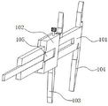
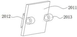
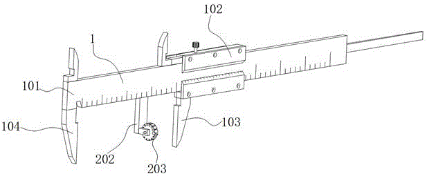
请参阅图1~11,本发明实施例中,一种针头生产检验用长度检测装置,包括游标卡尺1,游标卡尺1是由主尺101、游标102、活动内测量爪103以及固定内测量爪104组成,固定内测量爪104固定于主尺101底端的一端,游标102滑动连接于主尺101的外侧,活动内测量爪103固定于游标102底端的一端,游标102的外壁一侧开设有T型槽105,游标102的外壁一侧设置有用于对待检测的针头进行辅助支撑的支撑组件2,支撑组件2包括用于对不同型号的针头进行夹持的夹持单元203、用于将夹持单元203与游标102进行连接的卡合单元201以及为夹持单元203提供安装支撑的连接单元202;Please refer to Figures 1-11. In an embodiment of the present invention, a needle length detection device for production inspection includes a vernier caliper 1. The vernier caliper 1 is composed of a
其中,夹持单元203包括橡胶转盘2031、夹持槽2032以及插接槽2033,夹持槽2032开设于橡胶转盘2031的外壁一端并贯穿至橡胶转盘2031的另一端,插接槽2033自夹持槽2032的内壁一侧贯穿至橡胶转盘2031的外侧,夹持槽2032的数量设置有多个,多个夹持槽2032以橡胶转盘2031的圆心为中心呈环形均匀分布且多个夹持槽2032的内壁直径依次递减,且夹持槽2032的内壁直径与待测针头的外径相匹配。Wherein, the
在本实施例中,在需要进行针头长度测量时,可先拉动游标102移动远离固定内测量爪104一段距离,此距离长于待测针头的长度,之后通过卡合单元201将整个支撑组件2与游标102进行连接,使橡胶转盘2031位于固定内测量爪104与活动内测量爪103之间,其中有一个夹持槽2032的中心线会与固定内测量爪104、活动内测量爪103中心线重合,此时可转动橡胶转盘2031,使与待测针头直径相匹配的那个夹持槽2032转动至固定内测量爪104、活动内测量爪103中间位置,此时即可将待测针头安装至夹持槽2032内部,在此过程中可通过两个方式进行安装:In this embodiment, when it is necessary to measure the length of the needle, the
第一种,是将待测针纵向从橡胶转盘2031的一端插入至夹持槽2032并穿过夹持槽2032,并使待测针头的一端与活动内测量爪103的内侧贴合;The first one is to insert the needle to be measured longitudinally from one end of the
第二种,使将待测针头横向对准插接槽2033并挤压待测针头,使插接槽2033受力形变,从而使待测针头能够滑入至夹持槽2032内部,之后在对待测针头进行移动使其一端与活动内测量爪103的内侧贴合;The second method is to align the needle to be tested laterally with the
在完成待测针头安装后,即可移动游标102向固定内测量爪104方向移动,从而使待测针头的另一端与固定内测量爪104的内侧贴合,此时读取数字即为待测针头的长度数值,通过以上操作可使待测针头被测量时器处于水平状态,其测量数据精准,且通过夹持单元203对待测针头的夹持限位,可有效释放检测人员的双手,使其能够更好对游标卡尺1进行操作,继而进一步的提高了针头检测的工作效率。After the needle to be tested is installed, the
请着重参阅图9~11,插接槽2033的数量与夹持槽2032的数量相匹配且一一对应,多个插接槽2033的内壁宽度也依次递减且小于插接槽2033的内壁直径;橡胶转盘2031的外壁轨迹呈涡状线结构,且橡胶转盘2031最大半径线与最大直径的夹持槽2032中心点相重合。Please refer to Figures 9-11, the number of
在本实施例中:通过插接槽2033可便于针头安装至夹持槽2032内部,通过多个不同直径大小的夹持槽2032可适应不用直径大小针头的测量操作,由于多个夹持槽2032的圆心位于同一个同心圆轨迹上,随着夹持槽2032的内径减小,其插接槽2033贯穿至橡胶转盘2031的深度也随着增加,而过深插接槽2033不便于直径小的针头安装,的因此通过橡胶转盘2031的涡状外壁的结构,可使不同直径的夹持槽2032所对应的插接槽2033的深度也能够随之变化,使多个插接槽2033的深度能够便于不同直径针头安装。In this embodiment: the
请着重参阅图1~11,卡合单元201包括设置于游标102外壁一侧连接座2011,连接座2011的外壁一侧固定连接有与游标102套接的T型座2012,连接座2011的外壁另一侧固定连接有两个固定套筒2013;Please refer to Figures 1-11. The engaging
转动连接于两个固定套筒2013内侧的转动轴2014,转动轴2014的一端延伸至连接座2011外部一端,且转动轴2014的外壁连接有吸附块2015、限位卡块2016,限位卡块2016位于连接座2011的一端,吸附块2015位于两个固定套筒2013之间;连接座2011的长度与游标102的长度相匹配,T型座2012的外壁尺寸与T型槽105内壁尺寸相匹配;吸附块2015呈竖直状态与连接座2011相贴合时,限位卡块2016与连接座2011之间呈垂直状态,且吸附块2015靠近连接座2011一侧内嵌有磁吸块;Rotate the
连接单元202包括固定连接于转动轴2014一端的连接臂2021,连接臂2021位于限位卡块2016远离连接座2011的一端;The connecting
固定连接于连接臂2021外壁一侧靠近底端位置处的两个支撑座2022,两个支撑座2022对称分布且内部开设有转动槽2024;Fixedly connected to the two
转动连接于转动槽2024内部且贯穿至支撑座2022外部两端的多边形转柱2023,橡胶转盘2031位于两个支撑座2022的中间位置且套接在多边形转柱2023的外侧,且与连接臂2021距离最远的一个夹持槽2032位于主尺101的正下方并位于活动内测量爪103与固定内测量爪104之间,橡胶转盘2031与多边形转柱2023相接触的位置处开设有与多边形转柱2023外壁相匹配的多边孔槽2034。Rotate the polygonal
在本实施例中:在需要对支撑组件2进行安装时,可先将转动转动轴2014使吸附块2015与连接座2011之间分离且呈90度垂直状态,此时限位卡块2016会同步转动至竖直状态与连接座2011相平行,之后将T型座2012与T型槽105对齐并完全插入至T型槽105内部,此时连接座2011一侧与游标102贴合、连接座2011的两端与游标102两端对齐,之后反向转动转动轴2014,使吸附块2015侧面的磁吸块与连接座2011表面贴合,通过磁吸块的吸力吸附于连接座2011上可实现转动轴2014的固定,与此同时限位卡块2016会同步转动至与连接座2011、游标102相垂直的状态,此时连接座2011与游标102之间将无法进行X轴方向的相对位移,配合T型块2012与T型槽105的Y、Z轴方向的限位,即实现了连接座2011与游标102的连接固定,此时的橡胶转盘2031的一个夹持槽2031位于活动内测量爪103与固定内测量爪104之间,通过此结构可便于将待测针头固定限位在活动内测量爪103与固定内测量爪104之间,并使待测针头保持水平状态,以此使测量数据保持良好的精准度,通过多边孔槽2034可便于橡胶转盘2031与多边形转轴2023进行安装,并使橡胶转盘2031转动时不会与多边形转轴2023之间发生错位现象,通过多边形转轴2023可为橡胶转盘2031的转动提供支撑。In this embodiment: when the support assembly 2 needs to be installed, the
请着重参阅图7~8,支撑座2022的内部设置有用于对多边形转柱2023转动进行定位的定位组件3,定位组件3包括设置在支撑座2022内部并贯穿至转动槽2024内部的伸缩滚珠301,支撑座2022内部开设有与伸缩滚珠301外壁直径相匹配的伸缩槽;Please refer to Figures 7-8, the inside of the
设置于伸缩槽内部并位于伸缩滚珠301一侧的伸缩弹簧302;伸缩滚珠301的数量设置有四个,四个伸缩滚珠301两两一组,一组伸缩滚珠301呈水平对称分布,另一组伸缩滚珠301呈竖直对称分布,多边形转柱2023的外壁边数与夹持槽2032的数量相匹配且一一对应。The
在本实施例中:在需要将橡胶转盘2031与支撑座2022进行安装时,可先将橡胶转盘2031放置于两个支撑座202的中间,之后将多边形转柱2023从一个支撑座2022的一端插入至转动槽2024内部去,并贯穿多边孔槽2034以及另一个支撑座2022上的装动槽2024,即完成了橡胶转盘2031的安装,此时多个伸缩滚珠301可对多边形转柱2023的多边形面进行限位,多边形转柱2023的棱角与转动槽2024的内壁贴合,在转动橡胶转盘2031时,橡胶转盘2031将带动多边形转柱2023进行转动,此时多边形转柱2023的棱角将对伸缩滚珠301形成挤压,使伸缩滚珠301移动挤压伸缩弹簧302收缩,从而便于多边形转柱2023转动,当多边形转柱2023的一个棱角转动与伸缩滚珠301分离时,伸缩滚珠301即会在伸缩弹簧302的作用下自动复位,从而再次对多边形转柱2023进行限位,通过多个伸缩滚珠301的配合即可实现橡胶转盘2031转动定位,使一个夹持槽2032能够保持在活动内测量爪103与固定内测量爪104之间。In this embodiment: when the
以上所述的,仅为本发明较佳的具体实施方式,但本发明的保护范围并不局限于此,任何熟悉本技术领域的技术人员在本发明揭露的技术范围内,根据本发明的技术方案及其发明构思加以等同替换或改变,都应涵盖在本发明的保护范围之内。The above is only a preferred embodiment of the present invention, but the scope of protection of the present invention is not limited thereto, any person familiar with the technical field within the technical scope disclosed in the present invention, according to the technology of the present invention Any equivalent replacement or change of the scheme and its inventive concepts shall fall within the protection scope of the present invention.
Claims (9)
Priority Applications (1)
| Application Number | Priority Date | Filing Date | Title |
|---|---|---|---|
| CN202210952836.6A CN115014165B (en) | 2022-08-10 | 2022-08-10 | A length detection device for needle production inspection |
Applications Claiming Priority (1)
| Application Number | Priority Date | Filing Date | Title |
|---|---|---|---|
| CN202210952836.6A CN115014165B (en) | 2022-08-10 | 2022-08-10 | A length detection device for needle production inspection |
Publications (2)
| Publication Number | Publication Date |
|---|---|
| CN115014165A CN115014165A (en) | 2022-09-06 |
| CN115014165B true CN115014165B (en) | 2022-11-04 |
Family
ID=83065919
Family Applications (1)
| Application Number | Title | Priority Date | Filing Date |
|---|---|---|---|
| CN202210952836.6A Active CN115014165B (en) | 2022-08-10 | 2022-08-10 | A length detection device for needle production inspection |
Country Status (1)
| Country | Link |
|---|---|
| CN (1) | CN115014165B (en) |
Citations (17)
| Publication number | Priority date | Publication date | Assignee | Title |
|---|---|---|---|---|
| GB2129131A (en) * | 1982-10-27 | 1984-05-10 | Massey Ferguson Perkins Ltd | Caliper gauge |
| US4611404A (en) * | 1983-12-29 | 1986-09-16 | Arsenault Ronald G | Caliper for thread measurement |
| US4731931A (en) * | 1987-03-16 | 1988-03-22 | Andromeda Technology, Inc. | Caliper system |
| JP4113903B1 (en) * | 2007-01-31 | 2008-07-09 | 株式会社ニチリン | Concentricity measuring instrument and concentricity measuring method using the same |
| CN203216402U (en) * | 2013-04-16 | 2013-09-25 | 上海海洋大学 | Vernier caliper for measuring the thickness of irregular object |
| CN206479105U (en) * | 2017-02-23 | 2017-09-08 | 苏州建设监理有限公司 | Micrometer |
| CN206818082U (en) * | 2017-06-20 | 2017-12-29 | 李佳霖 | A kind of senior middle school's natural sciences Physical Experiment micrometer caliper |
| CN107708551A (en) * | 2015-04-14 | 2018-02-16 | 半岛骨科(私人)有限公司 | Femoral Head Measuring Device |
| CN207113748U (en) * | 2017-08-08 | 2018-03-16 | 苏州美特精密模具标准件有限公司 | Slide measure subsidiary tool |
| CN209069136U (en) * | 2018-12-30 | 2019-07-05 | 苏州爱科德精密仪器有限公司 | A kind of adjustable gage button outside micrometer |
| CN210220863U (en) * | 2019-08-05 | 2020-03-31 | 苏州市豪威自动化设备有限公司 | Micrometer convenient to operation of taking |
| CN210704022U (en) * | 2019-10-31 | 2020-06-09 | 钱娅琴 | Tip flash removed device is used in aluminum product processing |
| CN211696117U (en) * | 2020-03-27 | 2020-10-16 | 长春市宝成伟业汽车零部件有限公司 | Micrometer |
| CN214255600U (en) * | 2020-12-11 | 2021-09-21 | 广州宇城信息科技有限公司 | Cable fixing structure for LED screen |
| CN214543378U (en) * | 2021-05-13 | 2021-10-29 | 田托 | Categorised fixing device of power cable |
| CN216081202U (en) * | 2021-10-27 | 2022-03-18 | 苏州浩弓精密工业有限公司 | External micrometer with protective structure for detecting part size |
| CN216422356U (en) * | 2021-12-08 | 2022-05-03 | 浙江中航来宝精工科技有限公司 | A fast switching device for positioning plunger clamp with high assembly efficiency |
Family Cites Families (1)
| Publication number | Priority date | Publication date | Assignee | Title |
|---|---|---|---|---|
| CN206084605U (en) * | 2016-08-26 | 2017-04-12 | 台州群发自动化设备有限公司 | Many station machine of efficient bed |
-
2022
- 2022-08-10 CN CN202210952836.6A patent/CN115014165B/en active Active
Patent Citations (17)
| Publication number | Priority date | Publication date | Assignee | Title |
|---|---|---|---|---|
| GB2129131A (en) * | 1982-10-27 | 1984-05-10 | Massey Ferguson Perkins Ltd | Caliper gauge |
| US4611404A (en) * | 1983-12-29 | 1986-09-16 | Arsenault Ronald G | Caliper for thread measurement |
| US4731931A (en) * | 1987-03-16 | 1988-03-22 | Andromeda Technology, Inc. | Caliper system |
| JP4113903B1 (en) * | 2007-01-31 | 2008-07-09 | 株式会社ニチリン | Concentricity measuring instrument and concentricity measuring method using the same |
| CN203216402U (en) * | 2013-04-16 | 2013-09-25 | 上海海洋大学 | Vernier caliper for measuring the thickness of irregular object |
| CN107708551A (en) * | 2015-04-14 | 2018-02-16 | 半岛骨科(私人)有限公司 | Femoral Head Measuring Device |
| CN206479105U (en) * | 2017-02-23 | 2017-09-08 | 苏州建设监理有限公司 | Micrometer |
| CN206818082U (en) * | 2017-06-20 | 2017-12-29 | 李佳霖 | A kind of senior middle school's natural sciences Physical Experiment micrometer caliper |
| CN207113748U (en) * | 2017-08-08 | 2018-03-16 | 苏州美特精密模具标准件有限公司 | Slide measure subsidiary tool |
| CN209069136U (en) * | 2018-12-30 | 2019-07-05 | 苏州爱科德精密仪器有限公司 | A kind of adjustable gage button outside micrometer |
| CN210220863U (en) * | 2019-08-05 | 2020-03-31 | 苏州市豪威自动化设备有限公司 | Micrometer convenient to operation of taking |
| CN210704022U (en) * | 2019-10-31 | 2020-06-09 | 钱娅琴 | Tip flash removed device is used in aluminum product processing |
| CN211696117U (en) * | 2020-03-27 | 2020-10-16 | 长春市宝成伟业汽车零部件有限公司 | Micrometer |
| CN214255600U (en) * | 2020-12-11 | 2021-09-21 | 广州宇城信息科技有限公司 | Cable fixing structure for LED screen |
| CN214543378U (en) * | 2021-05-13 | 2021-10-29 | 田托 | Categorised fixing device of power cable |
| CN216081202U (en) * | 2021-10-27 | 2022-03-18 | 苏州浩弓精密工业有限公司 | External micrometer with protective structure for detecting part size |
| CN216422356U (en) * | 2021-12-08 | 2022-05-03 | 浙江中航来宝精工科技有限公司 | A fast switching device for positioning plunger clamp with high assembly efficiency |
Non-Patent Citations (1)
| Title |
|---|
| 内孔环槽测量专用卡尺;刘玉喜;《铁道机车车辆工人》;19941231(第01期);全文 * |
Also Published As
| Publication number | Publication date |
|---|---|
| CN115014165A (en) | 2022-09-06 |
Similar Documents
| Publication | Publication Date | Title |
|---|---|---|
| CN104713498B (en) | Automatic anglec of rotation detecting tool under a kind of supported at three point | |
| CN114353620A (en) | Composite measuring device for shaft and gear | |
| CN108827216A (en) | A kind of cylinder sleeve of engine inner diameter measuring device | |
| CN106769428A (en) | A kind of pinpoint chuck experimental rig in rock sample axle center | |
| CN118376194A (en) | Equipment and method for detecting inner diameter and outer diameter of combustion chamber shell part | |
| CN115014165B (en) | A length detection device for needle production inspection | |
| CN206095163U (en) | Diameter of cylinder test position | |
| CN105643585A (en) | Convenient-to-use recording pen assembly for connecting electric fusion pipe | |
| WO2013037190A1 (en) | Inner diameter micrometer | |
| CN205505912U (en) | Flexibility of detection gear is beated and is examined utensil | |
| CN205505894U (en) | Gear ring radial runout measures automatic correcting device | |
| CN106813572A (en) | A kind of dentistry rotates apparatus radial run-out detection means | |
| CN217738079U (en) | Comprehensive checking fixture for size of lower protective pipe | |
| CN215491403U (en) | Slip teeth of a cogwheel is beated and is measured anchor clamps | |
| CN117554221A (en) | A device for detecting the hardness of surrounding rock at the tunnel face | |
| CN215064276U (en) | Wind power generation coaxiality detection device | |
| CN106813571A (en) | A kind of dentistry rotates apparatus radial run-out detection means | |
| CN212007047U (en) | Centering detection mechanism for stator and rotor | |
| CN203893819U (en) | Lead measuring device for cemented carbide inner-cooling spiral hole | |
| CN204935424U (en) | A kind of stationary fixture measuring distance over bar value | |
| CN107228616A (en) | A kind of form and position tolerance detection means | |
| CN114526703A (en) | Adjustable machine part thickness measurement detection device | |
| CN209116931U (en) | Measure the measurer of the intersection height of the intermediate measurement point and basal plane of helicoid on part | |
| CN210321652U (en) | Hand-held type ultrasonic thickness gauge | |
| CN207649530U (en) | Drill bit back angle measuring apparatus |
Legal Events
| Date | Code | Title | Description |
|---|---|---|---|
| PB01 | Publication | ||
| PB01 | Publication | ||
| SE01 | Entry into force of request for substantive examination | ||
| SE01 | Entry into force of request for substantive examination | ||
| GR01 | Patent grant | ||
| GR01 | Patent grant | ||
| PE01 | Entry into force of the registration of the contract for pledge of patent right | ||
| PE01 | Entry into force of the registration of the contract for pledge of patent right |
Denomination of invention: A length detection device for needle production inspection Granted publication date: 20221104 Pledgee: Heze rural commercial bank Limited by Share Ltd. Pledgor: SHANDONG KERUI MEDICAL SUPPLIES Co.,Ltd. Registration number: Y2024980001360 |
|
| CB03 | Change of inventor or designer information | ||
| CB03 | Change of inventor or designer information |
Inventor after: Yang Feng Inventor after: Li Changjing Inventor after: Zhang Xiaolin Inventor after: Fu Jing Inventor before: Fu Jing |
|
| PC01 | Cancellation of the registration of the contract for pledge of patent right | ||
| PC01 | Cancellation of the registration of the contract for pledge of patent right |
Granted publication date: 20221104 Pledgee: Heze rural commercial bank Limited by Share Ltd. Pledgor: SHANDONG KERUI MEDICAL SUPPLIES Co.,Ltd. Registration number: Y2024980001360 |