CN115156830A - Multi-station welding device for processing dust removal cloth bag - Google Patents
Multi-station welding device for processing dust removal cloth bag Download PDFInfo
- Publication number
- CN115156830A CN115156830A CN202210901978.XA CN202210901978A CN115156830A CN 115156830 A CN115156830 A CN 115156830A CN 202210901978 A CN202210901978 A CN 202210901978A CN 115156830 A CN115156830 A CN 115156830A
- Authority
- CN
- China
- Prior art keywords
- air
- frame
- cylinder
- rod
- mounting
- Prior art date
- Legal status (The legal status is an assumption and is not a legal conclusion. Google has not performed a legal analysis and makes no representation as to the accuracy of the status listed.)
- Granted
Links
- 238000003466 welding Methods 0.000 title claims abstract description 55
- 239000000428 dust Substances 0.000 title claims abstract description 25
- 239000004744 fabric Substances 0.000 title claims abstract description 21
- 229910000831 Steel Inorganic materials 0.000 claims description 94
- 239000010959 steel Substances 0.000 claims description 94
- 238000003860 storage Methods 0.000 claims description 19
- 230000007246 mechanism Effects 0.000 claims description 11
- 230000017105 transposition Effects 0.000 claims description 7
- 230000009471 action Effects 0.000 claims description 6
- 238000009434 installation Methods 0.000 claims description 5
- 230000008878 coupling Effects 0.000 claims description 2
- 238000010168 coupling process Methods 0.000 claims description 2
- 238000005859 coupling reaction Methods 0.000 claims description 2
- 239000000463 material Substances 0.000 description 10
- 230000000694 effects Effects 0.000 description 4
- 238000000034 method Methods 0.000 description 3
- 230000008569 process Effects 0.000 description 3
- 230000002159 abnormal effect Effects 0.000 description 2
- 238000006243 chemical reaction Methods 0.000 description 2
- 238000007599 discharging Methods 0.000 description 2
- 230000001360 synchronised effect Effects 0.000 description 2
- 230000009286 beneficial effect Effects 0.000 description 1
- 230000007547 defect Effects 0.000 description 1
- 238000004519 manufacturing process Methods 0.000 description 1
- 238000012986 modification Methods 0.000 description 1
- 230000004048 modification Effects 0.000 description 1
- 230000009467 reduction Effects 0.000 description 1
Images


Classifications
-
- B—PERFORMING OPERATIONS; TRANSPORTING
- B23—MACHINE TOOLS; METAL-WORKING NOT OTHERWISE PROVIDED FOR
- B23K—SOLDERING OR UNSOLDERING; WELDING; CLADDING OR PLATING BY SOLDERING OR WELDING; CUTTING BY APPLYING HEAT LOCALLY, e.g. FLAME CUTTING; WORKING BY LASER BEAM
- B23K37/00—Auxiliary devices or processes, not specially adapted for a procedure covered by only one of the other main groups of this subclass
- B23K37/04—Auxiliary devices or processes, not specially adapted for a procedure covered by only one of the other main groups of this subclass for holding or positioning work
- B23K37/047—Auxiliary devices or processes, not specially adapted for a procedure covered by only one of the other main groups of this subclass for holding or positioning work moving work to adjust its position between soldering, welding or cutting steps
-
- Y—GENERAL TAGGING OF NEW TECHNOLOGICAL DEVELOPMENTS; GENERAL TAGGING OF CROSS-SECTIONAL TECHNOLOGIES SPANNING OVER SEVERAL SECTIONS OF THE IPC; TECHNICAL SUBJECTS COVERED BY FORMER USPC CROSS-REFERENCE ART COLLECTIONS [XRACs] AND DIGESTS
- Y02—TECHNOLOGIES OR APPLICATIONS FOR MITIGATION OR ADAPTATION AGAINST CLIMATE CHANGE
- Y02P—CLIMATE CHANGE MITIGATION TECHNOLOGIES IN THE PRODUCTION OR PROCESSING OF GOODS
- Y02P70/00—Climate change mitigation technologies in the production process for final industrial or consumer products
- Y02P70/10—Greenhouse gas [GHG] capture, material saving, heat recovery or other energy efficient measures, e.g. motor control, characterised by manufacturing processes, e.g. for rolling metal or metal working
Landscapes
- Physics & Mathematics (AREA)
- Optics & Photonics (AREA)
- Engineering & Computer Science (AREA)
- Mechanical Engineering (AREA)
- Wire Processing (AREA)
Abstract
The invention discloses a multi-station welding device for processing a dust removal cloth bag, and relates to the field of processing of dust removal cloth bags.
Description
Technical Field
The invention relates to the field of dust removal cloth bag processing, in particular to a multi-station welding device for processing a dust removal cloth bag.
Background
When welding the steel skeleton of inboard installation to the dust removal sack, because the steel skeleton comprises a plurality of ring shape steel rings and linear type steel wire welding, consequently, the contact point that does not have steel wire and steel ring all will weld, the welding station is more, manual operation efficiency is lower, and because the conversion welding station that need not stop when the welding, lead to the welding time to increase, secondly, because steel wire and steel ring part, so need to the steel wire material loading many times, above multiple condition all can prolong man-hour, reduce work efficiency, improve manufacturing cost, consequently, to sum up, need carry out relevant innovative design to equipment.
Disclosure of Invention
Aiming at the defects in the prior art, the invention aims to provide the multi-station welding device for processing the dust removal cloth bag, so that multi-station welding and conversion are convenient to realize in the welding process of the steel skeleton of the dust removal cloth bag, the steel wires are quickly fed, and the welding effect is improved.
In order to achieve the purpose, the invention provides the following technical scheme: the utility model provides a multistation welding set is used in processing of dust removal sack which characterized in that: including first motor, second motor, air pump and device frame, still include:
the device frame is fixedly arranged on the base frame, the air pump is fixedly arranged on the base frame, and the middle part of the upper side of the base frame is provided with an installation groove;
the first clamping mechanism comprises a third air rod, a third air cylinder, a second moving frame and a fixing sleeve, and the second moving frame enables the fixing sleeve to fixedly clamp and release the steel ring under the moving action of the third air rod and the third air cylinder;
the clamping block Tong air bag is inflated and expanded and deflated, and the elastic force of the first spring acts on the first placing sleeve or the second placing sleeve to move out and retract, so that the steel hoop is fixedly clamped and released;
the feeding mechanism comprises a first rotating gear, a special-shaped block, a sliding column, a pushing rod, a rotating rod and a feeding plate, wherein the first rotating gear enables the pushing rod connected with the sliding column to drive the rotating rod to rotate through the special-shaped block, so that the feeding plate connected with the rotating rod moves up and down to realize reciprocating feeding of the steel wire;
and the transposition mechanism comprises a second rotating gear and a first placing sleeve, and the second rotating gear drives the first placing sleeve to rotate so as to realize transposition welding of the steel framework.
Preferably, the device frame seat upside is provided with two circular arc grooves, the mounting groove is located between two circular arc grooves, be provided with many pairs of shifting chutes on the circular arc groove, all be provided with a pair of fixed cover in every pair of shifting chute, both sides are fixed mounting respectively around the device frame seat have a third cylinder, the inside both sides of mounting groove are fixed mounting respectively has a third cylinder, the third cylinder passes through fourth gas-supply pipe and air pump intercommunication, the cooperation is installed the third air pole in the third cylinder, the extension end fixed mounting of third air pole has the second to remove the frame, the second removes the fixed cover of one side that the frame is close respectively fixed connection with it.
Preferably, the rear side of the device frame seat is provided with a pair of second rotating gears which are meshed and connected, a second motor is installed on one of the second rotating gears, one side of the second rotating gear, which is close to the device frame seat, is fixedly coupled with a first placing sleeve, a mounting frame is fixedly installed on a base frame between the second rotating gear and the first placing sleeve, and the first placing sleeve is slidably installed on the mounting frame.
Preferably, a pair of first rotating gears connected in a meshed mode is installed on the front side of the device frame seat, the two first rotating gears are rotatably installed on the first moving frame, a first motor is installed on one first rotating gear, a special-shaped block is fixedly installed at the center of the rear side of the first rotating gear, an upper material box and a material storage box are fixedly installed at the center of the rear side of the special-shaped block, a top cover is installed on the upper side of the material storage box, and the lower side of the material storage box is arranged to be a slope.
Preferably, be provided with the mounting bracket on the base frame between first rotating gear and the device frame seat, and the mounting bracket is fixed to be set up on first removal frame, and the inboard slidable mounting of first removal frame here has the second to place the cover, first place cover and second place to put and sheatheeing in respectively slidable mounting have the grip block, first place cover and second place the cover inside and do not be provided with the gasbag, grip block inside end fixed mounting has first spring, and first spring other end fixed mounting is inside first place the cover, the gasbag passes through third gas-supply pipe and air pump intercommunication.
Preferably, the device frame seat front side fixed mounting has the second cylinder, and removal in the second cylinder is installed at the second gas pole, the stretch out of second gas pole with first removal frame fixed mounting, and the second cylinder passes through the second gas-supply pipe intercommunication with the air pump.
Preferably, the inside upside of going up the magazine is provided with the discharge gate, and discharge gate and storage box intercommunication, goes up magazine internally movable and installs the flitch, goes up the flitch downside and rotates and be connected with a plurality of dwangs, goes up magazine downside and removes and install the push rod, and the dwang other end rotates and installs on the push rod, and the push rod stretches out end fixed connection sliding column, and the sliding column other end slidable mounting is inside the special-shaped piece, goes up flitch downside fixed mounting and has the second spring, and second spring other end fixed mounting is inside last magazine.
Preferably, the device frame seat upside is provided with the roof, and the welder is installed to the roof downside, and the welder is connected with external control device, and roof downside both ends are fixed mounting respectively has first gas pole, and first gas pole removes to be installed in first cylinder, and first cylinder fixed mounting is on the base frame, and first cylinder passes through first gas-supply pipe and air pump intercommunication.
Compared with the prior art, the invention has the following beneficial effects:
1. according to the multi-station welding device for processing the dust removal cloth bag, the third air rod, the third air cylinder, the second moving frame and the fixing sleeve are used in a matched mode, the fixing sleeve is enabled to fixedly clamp and release a steel ring under the moving effect of the third air rod and the third air cylinder by the second moving frame, and through the matched use of the first placing sleeve, the second placing sleeve, the clamping block, the air bag and the first spring, the clamping block Tong air bag is inflated and expanded and deflated, and the elastic force of the first spring acts on the first placing sleeve or the second placing sleeve to movably extend and retract, so that the steel ring is fixedly clamped and released.
2. According to the multi-station welding device for processing the dust removal cloth bag, the first rotating gear, the special-shaped block, the sliding column, the pushing rod, the rotating rod and the feeding plate are used in a matched mode, the pushing rod connected with the sliding column drives the rotating rod to rotate through the special-shaped block, the feeding plate connected with the rotating rod is further made to move up and down, reciprocating feeding of steel wires is achieved, the second rotating gear is used in a matched mode with the first placing sleeve, and the second rotating gear drives the first placing sleeve to rotate, so that transposition welding of a steel framework is achieved.
Drawings
FIG. 1 is a schematic perspective view of a multi-station welding device for processing a dust removal cloth bag according to the present invention;
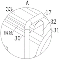
FIG. 2 is an enlarged schematic view of the structure at A in FIG. 1 according to the present invention;
FIG. 3 is a schematic top view of the first receiving sleeve and the clamping block of FIG. 1 according to the present invention;
FIG. 4 is a schematic cross-sectional view taken along line B-B of FIG. 3 according to the present invention;
FIG. 5 is a schematic structural view of the upper magazine and the storage magazine and associated parts of FIG. 1 according to the present invention;
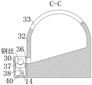
FIG. 6 is a schematic cross-sectional view taken at C-C of FIG. 5 according to the present invention;
FIG. 7 is a schematic cross-sectional view taken at D-D in FIG. 5 according to the present invention;
1. a base frame; 2. a first cylinder; 3. a first gas lever; 4. a top plate; 5. a welding device; 6. a first rotating gear; 7. a special-shaped block; 8. a first gas pipe; 9. a second gas delivery pipe; 10. a second cylinder; 11. a first motor; 12. a second gas lever; 13. a first moving frame; 14. a sliding post; 15. a second motor; 16. a second rotating gear; 17. a third gas delivery pipe; 18. a mounting frame; 19. a first placement sleeve; 20. a clamping block; 21. an air pump; 22. a fourth gas delivery pipe; 23. a third cylinder; 24. a third gas lever; 25. a second movable frame; 26. fixing a sleeve; 27. a moving groove; 28. mounting grooves; 29. a device frame seat; 30. feeding a material box; 31. a second placing sleeve; 32. a storage box; 33. a top cover; 34. a first spring; 35. an air bag; 36. a discharge port; 37. feeding plates; 38. rotating the rod; 39. a second spring; 40. a pushing rod.
Detailed Description
The embodiment of the multi-station welding device for processing the dust removal cloth bag is further explained with reference to fig. 1-7.
Referring to fig. 1, 3 and 4, the multi-station welding device for processing the dust removal cloth bag comprises a first motor 11, a second motor 15, an air pump 21, a device frame and a base frame 1, wherein the device frame is fixedly arranged on the base frame 1, the air pump 21 is fixedly arranged on the base frame 1, and an installation groove 28 is formed in the middle of the upper side of the base frame 1.
The first clamping mechanism comprises a third air rod 24, a third air cylinder 23, a second moving frame 25 and a fixing sleeve 26, and the second moving frame 25 enables the fixing sleeve 26 to realize fixed clamping and releasing on the steel ring under the moving action of the third air rod 24 and the third air cylinder 23.
The second clamping mechanism comprises a first placing sleeve 19, a second placing sleeve 31, a clamping block 20, an air bag 35 and a first spring 34, wherein the clamping block 20 Tong air bag 35 expands and contracts when inflated and deflates, and the elastic force of the first spring 34 acts in the first placing sleeve 19 or the second placing sleeve 31 to move out and retract, so that the steel hoop is fixedly clamped and loosened.
The device frame seat 29 upside is provided with two circular arc grooves, mounting groove 28 is located between two circular arc grooves, be provided with many pairs of shifting chutes 27 on the circular arc groove, all be provided with a pair of fixed cover 26 in every pair of shifting chute 27, both sides fixed mounting has a third cylinder 23 respectively around the device frame seat 29, the inside both sides fixed mounting has a third cylinder 23 respectively of mounting groove 28, third cylinder 23 is through fourth gas-supply pipe 22 and air pump 21 intercommunication, third gas pole 24 is installed in the cooperation in the third cylinder 23, the protruding end fixed mounting of third gas pole 24 has the second to move frame 25, the fixed cover 26 of one side that the second moves frame 25 fixed connection is close with it respectively.
Be provided with the mounting bracket 18 on the base frame 1 between first rotary gear 6 and the device frame seat 29, and the mounting bracket 18 is fixed to be set up on first removal frame 13, and the inboard slidable mounting of first removal frame 13 here has the second to place cover 31, first place cover 19 and second place cover 31 on respectively slidable mounting have grip block 20, first place cover 19 and second place the inside gasbag 35 that is provided with respectively of cover 31, the inboard end fixed mounting of grip block 20 has first spring 34, and first spring 34 other end fixed mounting is first place inside the cover 19, gasbag 35 communicates with air pump 21 through third gas-supply pipe 17.
Firstly, the steel hoops arranged at two ends of a steel skeleton of a dust removal cloth bag are taken out, one of the steel hoops penetrates through the feeding box 30 and the storage box 32 from the rear side and is placed on the second placing sleeve 31, the other steel hoop is placed on the first placing sleeve 19, then the air pump 21 is started, the air pump 21 inflates the air bag 35 through the third air pipe 17, the air bag 35 inflates and expands to drive the clamping block 20 arranged at the outer side of the air bag 35 to move and extend out of the first placing sleeve 19, the clamping block 20 strains the first spring 34 in the moving and extending process, and extends out along with the movement of the clamping block 20 to clamp and fix the steel hoops placed on the first placing sleeve 19 and the second placing sleeve 31, so that the steel hoops at two ends of the steel skeleton are fixedly placed, and then, the plurality of circular steel rings penetrate through the feeding box 30 and the storage box 32 from the rear side and are respectively placed between the fixing sleeves 26, after the circular steel rings are placed, the air pump 21 is started, the air pump 21 inflates the third air cylinder 23 through the fourth air conveying pipe 22, the number of the third air cylinders 23 is four in the whole device, the two air cylinders are arranged in the mounting groove 28, the other two sides of the third air cylinder are arranged outside the device frame seat 29, along with the increase of air in the third air cylinder 23, the third air rod 24 moves and extends out of the third air cylinder 23, the second moving frame 25 fixedly installed by extending out of the third air rod 24 moves in the device frame, the fixing sleeves 26 with the same circle center move towards one side close to the circular steel rings in opposite directions, the fixing of the circular steel rings is achieved, and in conclusion, the fixing of all the circular steel wires in the steel frame is achieved.
Referring to fig. 1, 2, 5, 6 and 7, the feeding mechanism includes a first rotary gear 6, a special-shaped block 7, a sliding column 14, a pushing rod 40, a rotating rod 38 and a feeding plate 37, the first rotary gear 6 drives the pushing rod 40 connected with the sliding column 14 to drive the rotating rod 38 to rotate through the special-shaped block 7, and then the feeding plate 37 connected with the rotating rod 38 moves up and down, so as to realize the reciprocating feeding of the steel wires.
A pair of first rotating gears 6 connected in a meshed mode is installed on the front side of the device frame seat 29, the two first rotating gears 6 are installed on the first moving frame 13 in a rotating mode, a first motor 11 is installed on one of the first rotating gears 6, a special-shaped block 7 is fixedly installed on the rear side center of circle of the first rotating gear 6, an upper material box 30 and a material storage box 32 are fixedly installed on the rear side center of circle of the special-shaped block 7, a top cover 33 is installed on the upper side of the material storage box 32, and the lower side of the material storage box 32 is arranged to be a slope.
Go up the inside upside of magazine 30 and be provided with discharge gate 36, and discharge gate 36 and storage box 32 intercommunication, go up magazine 30 internally movable mounting and have a flitch 37, go up flitch 37 downside and rotate and be connected with a plurality of dwang 38, go up magazine 30 downside movable mounting and have a lapse pole 40, the dwang 38 other end rotates and installs on lapse pole 40, lapse pole 40 stretches out end fixed connection sliding column 14, sliding column 14 other end slidable mounting is inside special-shaped piece 7, go up flitch 37 downside fixed mounting and have second spring 39, second spring 39 other end fixed mounting is inside last magazine 30.
After the ring shape steel ring on the steel skeleton is fixed, still need to weld vertical steel wire and couple together above-mentioned a plurality of ring shape steel rings fixed connection, therefore, start first motor 11, first motor 11 drives the rotation of the first rotating gear 6 rather than fixed coupling, make two first rotating gear 6 rotate simultaneously through the meshing effect, consequently, can realize installing the welding to the steel skeleton of two dust removal sack simultaneously, when first rotating gear 6 is rotatory, first rotating gear 6 drives the abnormal shape piece 7 rather than centre of a circle position fixed mounting and rotates simultaneously, abnormal shape piece 7 effect makes through slip post 14 make push rod 40 reciprocating motion in last magazine 30, thereby realize the work of linear type steel wire reciprocating feeding, its motion process is as follows: when the concave position of the special-shaped block 7 rotates to be connected with the sliding column 14, the special-shaped block 7 can drive the sliding column 14 to move to one side close to the special-shaped block 7, so that the sliding column 14 drives the pushing rod 40 fixedly connected with the sliding column to move to one side close to the special-shaped block 7 in the feeding box 30, the pushing rod 40 drives the rotating rod 38 connected with the sliding column to rotate, the rotating rod 38 drives the feeding plate 37 connected with the rotating rod to move downwards in the feeding box 30, when the feeding plate 37 moves downwards to the lower side of the discharging port 36, the linear steel wire slides down from the storage box 32, the linear steel wire after sliding falls down from the discharging port 36 to the upper side of the feeding plate 37, automatic feeding of the feeding plate 37 by the storage box 32 is realized, when the convex position of the special-shaped block 7 rotates to be connected with the sliding column 14, the special-shaped block 7 can drive the sliding column 14 to move to one side far from the special-shaped block 7, so that the sliding column 14 drives the pushing rod 40 fixedly connected with the sliding column 38 to move to one side far from the feeding plate 30, when the convex position of the sliding column 7 rotates to the feeding box 30, the linear steel wire is connected with the feeding plate, the linear steel wire is prevented from moving upwards, and the linear steel wire is tightly adhered to the linear steel wire and the linear steel wire is adhered to the linear steel wire, and the linear steel wire is adhered to the linear steel wire is prevented from the linear steel wire in the feeding box 30, and the linear steel wire is adhered to the linear steel wire.
Referring to fig. 1, the transposition mechanism includes a second rotating gear 16 and a first placing sleeve 19, and the second rotating gear 16 drives the first placing sleeve 19 to rotate, so as to realize transposition welding of the steel skeleton.
A pair of second rotating gears 16 which are meshed and connected are arranged on the rear side of the device frame seat 29, a second motor 15 is installed on one second rotating gear 16, one side, close to the device frame seat 29, of the second rotating gear 16 is fixedly connected with a first placing sleeve 19 in a shaft mode, an installing frame 18 is fixedly installed on the base frame 1 between the second rotating gear 16 and the first placing sleeve 19, and the first placing sleeve 19 is installed on the installing frame 18 in a sliding mode.
The front side of the device frame seat 29 is fixedly provided with a second air cylinder 10, the second air cylinder 10 is movably arranged in a second air rod 12, the second air rod 12 extends out of the first movable frame 13 and is fixedly arranged, and the second air cylinder 10 is communicated with the air pump 21 through a second air pipe 9.
The device frame base 29 upside is provided with roof 4, and 4 downside of roof are installed and are welded ware 5, and welding ware 5 is connected with external control device, and 4 downside both ends of roof are fixed mounting respectively has first gas pole 3, and first gas pole 3 removes and installs in first cylinder 2, and 2 fixed mounting of first cylinder are on base frame 1, and first cylinder 2 communicates with air pump 21 through first gas-supply pipe 8.
When the feeding plate 37 drives the linear steel wire to move upwards to be tightly attached to the steel ring and stop, the air pump 21 pumps air into the first air cylinder 2 through the first air delivery pipe 8, the first air rod 3 moves downwards in the first air cylinder 2 along with the reduction of the air in the first air cylinder 2, the first air rod 3 drives the top plate 4 fixedly installed at the extending end of the first air rod to move downwards together with the first air rod, the welding device 5 installed on the top plate 4 stops when contacting with the steel ring, wherein the welding device 5 comprises a plurality of welding heads, the welding device 5 is connected with an external control device, the external control device controls the switch of the welding device 5, when the welding device 5 moves downwards to stop, the welding heads installed on the welding device 5 are respectively and correspondingly placed at the positions where the steel ring contacts with the steel wire, so as to realize the welding at a plurality of positions at one time, and when one-time welding work is finished, the second motor 15 is started, the second motor 15 drives the second rotary gear 16 connected with the fixed shaft to rotate, under the action of meshing connection, the two second rotary gears 16 rotate synchronously, when the second rotary gears 16 rotate synchronously, the second rotary gears 16 drive the first placing sleeve 19 fixedly installed with the second rotary gears 16 to rotate, as the second placing sleeve 31 and the first placing sleeve 19 are both slidably installed on the installation frame 18, and a plurality of steel rings and steel hoops are welded and fixed by linear steel wires, the steel hoops are fixedly installed on the first placing sleeve 19 and the second placing sleeve 31, the fixing sleeve 26 is loosened to clamp the steel rings, when the second rotary gears 16 rotate, the steel hoops fixedly installed on the first placing sleeve 19 drive the steel rings to rotate together under the action of welding of the steel wires, so as to realize synchronous welding of a plurality of stations under the steel rings, the motor drives the whole framework to rotate for a certain angle through the second rotary gears 16 and the first placing sleeve 19 and then stops, the feeding box 30 is fed again by the operation of the first motor 11, and then the welding device 5 welds the position, the cycle is reciprocating, the operation is finished after a steel skeleton is completely formed, after all the operations are finished, the third air pipe 17 is closed, the fixation of the steel skeleton is released, the air pump 21 inflates the second air cylinder 10 through the second air pipe 9, the second air rod 12 in the second air cylinder 10 drives the first rotary gear 6 through the first movable frame 13, the second placing sleeve 31 and the mounting frame 18 move towards one side away from the steel skeleton together, and the steel skeleton can be taken out of the device skeleton seat 29 conveniently.
The working principle is as follows: one steel hoop penetrates through the feeding box 30 and the storage box 32 from the rear side and is placed on the second placing sleeve 31, the other steel hoop is placed on the first placing sleeve 19, the air pump 21 inflates the air bag 35 through the third air conveying pipe 17 to enable the clamping block 20 to move and extend out of the first placing sleeve 19, the clamping block 20 clamps and fixes the steel hoops placed on the first placing sleeve 19 and the second placing sleeve 31, then a plurality of circular steel rings penetrate through the rear side and are respectively placed between the fixed sleeves 26, the air pump 21 enables the third air cylinder 23 to drive the second moving frame 25 on the third air rod 24 to move in the device frame through the fourth air conveying pipe 22 to achieve the fixation of the circular steel rings, after the circular steel rings on the steel frame are fixed, the first motor 11 drives the two first rotating gears 6 which are connected in an engaged mode to rotate simultaneously, the first rotating gears 6 enable the sliding column 14 to drive the feeding box 40 to move in the feeding box 30 in a reciprocating mode through the special-shaped blocks 7, the pushing rod 40 makes the feeding plate 37 move up and down at the discharge port 36 side in the feeding box 30 through the rotating rod 38, thereby realizing the work of linear steel wire reciprocating feeding, when the steel wire is closely attached to the steel ring, the air pump 21 makes the first air cylinder 2 drive the top plate 4 on the first air rod 3 to move through the first air pipe 8, the welding device 5 installed on the top plate 4 carries out welding fixation to a plurality of positions, when one welding work is completed, the second rotary gear 16 can drive a plurality of steel rings to rotate together under the action of steel wire welding through the steel hoop fixedly installed on the first placing sleeve 19 when rotating, thereby realizing the synchronous welding of the next stations of a plurality of steel rings, after all the work is completed, the third air pipe 17 is closed, the fixation of the steel skeleton is released, the air pump 21 makes the second air cylinder 10 inflate through the second air pipe 9, the second air rod 12 in the second air cylinder 10 drives the first rotary gear 6, the second placing sleeve 31 and the mounting rack 18 to move towards the side away from the steel skeleton through the first moving frame 13, so that the steel skeleton can be taken out of the device frame seat 29 conveniently.
The above description is only a preferred embodiment of the present invention, and the protection scope of the present invention is not limited to the above embodiments, and all technical solutions belonging to the idea of the present invention belong to the protection scope of the present invention. It should be noted that modifications and embellishments within the scope of the invention may occur to those skilled in the art without departing from the principle of the invention, and are considered to be within the scope of the invention.
Claims (8)
1. The utility model provides a multistation welding set is used in processing of dust removal sack which characterized in that: including first motor (11), second motor (15), air pump (21) and device frame, still include:
the device frame is fixedly arranged on the base frame (1), the air pump (21) is fixedly arranged on the base frame (1), and the middle part of the upper side of the base frame (1) is provided with an installation groove (28);
the first clamping mechanism comprises a third air rod (24), a third air cylinder (23), a second moving frame (25) and a fixing sleeve (26), and the second moving frame (25) enables the fixing sleeve (26) to fixedly clamp and release the steel ring under the moving action of the third air rod (24) and the third air cylinder (23);
the second clamping mechanism comprises a first placing sleeve (19), a second placing sleeve (31), a clamping block (20), an air bag (35) and a first spring (34), the clamping block (20) Tongtong air bag (35) is inflated and expanded and deflated, and the elastic force of the first spring (34) acts in the first placing sleeve (19) or the second placing sleeve (31) to move, extend and retract, so that the steel hoop is fixedly clamped and released;
the feeding mechanism comprises a first rotating gear (6), a special-shaped block (7), a sliding column (14), a pushing rod (40), a rotating rod (38) and a feeding plate (37), wherein the first rotating gear (6) enables the pushing rod (40) connected with the sliding column (14) to drive the rotating rod (38) to rotate through the special-shaped block (7), and then the feeding plate (37) connected with the rotating rod (38) moves up and down to realize reciprocating feeding of steel wires;
the transposition mechanism comprises a second rotating gear (16) and a first placing sleeve (19), and the second rotating gear (16) drives the first placing sleeve (19) to rotate, so that transposition welding of the steel skeleton is achieved.
2. The multistation welding device for processing the dust removal cloth bag according to claim 1 is characterized in that: the device frame seat (29) upside is provided with two circular arc grooves, mounting groove (28) are located between two circular arc grooves, be provided with many pairs of shifting chute (27) on the circular arc groove, all be provided with a pair of fixed cover (26) in every pair of shifting chute (27), both sides fixed mounting has a third cylinder (23) respectively around device frame seat (29), mounting groove (28) inside both sides fixed mounting has a third cylinder (23) respectively, third cylinder (23) are through fourth gas-supply pipe (22) and air pump (21) intercommunication, third gas pole (24) are installed in the cooperation in third cylinder (23), the end fixed mounting that stretches out of third gas pole (24) has the second to remove frame (25), fixed cover (26) of one side that second removal frame (25) fixed connection is close with it respectively.
3. The multistation welding device for processing the dust removal cloth bag according to claim 2 is characterized in that: the rear side of the device frame seat (29) is provided with a pair of second rotating gears (16) which are connected in a meshed mode, a second motor (15) is installed on one of the second rotating gears (16), the second rotating gear (16) is close to one side of the device frame seat (29) and is fixedly connected with a first placing sleeve (19) in a shaft coupling mode, a mounting frame (18) is fixedly installed on the second rotating gear (16) and a first base frame (1) between the placing sleeves (19), and the first placing sleeve (19) is slidably installed on the mounting frame (18).
4. The multistation welding device for processing the dust removal cloth bag according to claim 3, characterized in that: a pair of first rotating gear (6) that the meshing is connected is installed to device frame seat (29) front side, and two first rotating gear (6) rotate and install on first removal frame (13), and first motor (11) are installed in one of them first rotating gear (6), and first rotating gear (6) rear side heart position fixed mounting has special-shaped piece (7), and special-shaped piece (7) rear side heart position fixed mounting has last magazine (30) and storage box (32), and top cap (33) are installed to storage box (32) upside, and storage box (32) downside sets up to the slope.
5. The multistation welding device for processing the dust removal cloth bag according to claim 4, characterized in that: be provided with mounting bracket (18) on base frame (1) between first rotating gear (6) and device frame seat (29), and mounting bracket (18) are fixed to be set up on first removal frame (13), and first removal frame (13) inboard slidable mounting at this place has the second to place cover (31), first cover (19) and the second of placing place on cover (31) respectively slidable mounting have grip block (20), first cover (19) and the second of placing are placed inside gasbag (35) of being provided with respectively of cover (31), grip block (20) inboard end fixed mounting has first spring (34), and first spring (34) other end fixed mounting is inside first cover (19) of placing, gasbag (35) are through third gas-supply pipe (17) and air pump (21) intercommunication.
6. The multistation welding device for processing the dust removal cloth bag according to claim 5, characterized in that: the device is characterized in that a second air cylinder (10) is fixedly mounted on the front side of the device frame seat (29), a second air rod (12) is mounted in the second air cylinder (10) in a movable mode, the second air rod (12) stretches out and is fixedly mounted with a first movable frame (13), and the second air cylinder (10) is communicated with an air pump (21) through a second air conveying pipe (9).
7. The multistation welding device for processing the dust removal cloth bag according to claim 4, characterized in that: go up inside upside of magazine (30) and be provided with discharge gate (36), and discharge gate (36) and storage box (32) intercommunication, go up magazine (30) internal movement and install flitch (37), it is connected with a plurality of dwang (38) to go up flitch (37) downside rotation, it has thrust rod (40) to go up magazine (30) downside movement and install, dwang (38) other end rotates and installs on thrust rod (40), thrust rod (40) stretch out end fixed connection slip post (14), slip post (14) other end slidable mounting is inside special-shaped block (7), it has second spring (39) to go up flitch (37) downside fixed mounting, second spring (39) other end fixed mounting is inside last magazine (30).
8. The multi-station welding device for processing the dust removal cloth bag according to claim 6, characterized in that: device frame seat (29) upside is provided with roof (4), and welding ware (5) are installed to roof (4) downside, and welding ware (5) are connected with external control device, and roof (4) downside both ends are fixed mounting respectively has first air bar (3), and first air bar (3) are removed and are installed in first cylinder (2), and first cylinder (2) fixed mounting is on base frame (1), and first cylinder (2) are through first gas-supply pipe (8) and air pump (21) intercommunication.
Priority Applications (1)
| Application Number | Priority Date | Filing Date | Title |
|---|---|---|---|
| CN202210901978.XA CN115156830B (en) | 2022-07-28 | 2022-07-28 | Multistation welding set is used in dust removal sack processing |
Applications Claiming Priority (1)
| Application Number | Priority Date | Filing Date | Title |
|---|---|---|---|
| CN202210901978.XA CN115156830B (en) | 2022-07-28 | 2022-07-28 | Multistation welding set is used in dust removal sack processing |
Publications (2)
| Publication Number | Publication Date |
|---|---|
| CN115156830A true CN115156830A (en) | 2022-10-11 |
| CN115156830B CN115156830B (en) | 2023-08-11 |
Family
ID=83476429
Family Applications (1)
| Application Number | Title | Priority Date | Filing Date |
|---|---|---|---|
| CN202210901978.XA Active CN115156830B (en) | 2022-07-28 | 2022-07-28 | Multistation welding set is used in dust removal sack processing |
Country Status (1)
| Country | Link |
|---|---|
| CN (1) | CN115156830B (en) |
Cited By (2)
| Publication number | Priority date | Publication date | Assignee | Title |
|---|---|---|---|---|
| CN115814528A (en) * | 2022-11-28 | 2023-03-21 | 常州市康安环保设备有限公司 | Self-cleaning bag-type dust collector |
| CN116337605A (en) * | 2023-02-13 | 2023-06-27 | 无锡元一建设工程有限公司 | A quick detection device for municipal administration rain sewage pipe |
Citations (7)
| Publication number | Priority date | Publication date | Assignee | Title |
|---|---|---|---|---|
| DE2134886A1 (en) * | 1971-07-13 | 1973-02-01 | Harry Gensch | Grid welding machine wire rod feeder - aligns and dispenses |
| KR20190137659A (en) * | 2018-06-01 | 2019-12-11 | 티제이케이 머시너리 (텐진) 컴퍼니 리미티드 | Integrated steel cage forming robot |
| CN112045361A (en) * | 2020-09-08 | 2020-12-08 | 安徽智宇环保滤材有限公司 | Dust removal filter bag skeleton welding process equipment |
| CN212470328U (en) * | 2020-04-15 | 2021-02-05 | 杨通秀 | Automatic welding device of reinforcement cage seam welder |
| CN213080521U (en) * | 2020-04-18 | 2021-04-30 | 四川利德建筑工程有限公司 | Positioning device for welding water conservancy foundation pile reinforcing steel bars |
| CN113275720A (en) * | 2021-06-04 | 2021-08-20 | 王岩韬 | Construction method for manufacturing reinforcement cage by roll welding machine for highway engineering |
| CN215115614U (en) * | 2021-04-09 | 2021-12-10 | 石丽晶 | Asphalt ductility detection device for highway engineering |
-
2022
- 2022-07-28 CN CN202210901978.XA patent/CN115156830B/en active Active
Patent Citations (7)
| Publication number | Priority date | Publication date | Assignee | Title |
|---|---|---|---|---|
| DE2134886A1 (en) * | 1971-07-13 | 1973-02-01 | Harry Gensch | Grid welding machine wire rod feeder - aligns and dispenses |
| KR20190137659A (en) * | 2018-06-01 | 2019-12-11 | 티제이케이 머시너리 (텐진) 컴퍼니 리미티드 | Integrated steel cage forming robot |
| CN212470328U (en) * | 2020-04-15 | 2021-02-05 | 杨通秀 | Automatic welding device of reinforcement cage seam welder |
| CN213080521U (en) * | 2020-04-18 | 2021-04-30 | 四川利德建筑工程有限公司 | Positioning device for welding water conservancy foundation pile reinforcing steel bars |
| CN112045361A (en) * | 2020-09-08 | 2020-12-08 | 安徽智宇环保滤材有限公司 | Dust removal filter bag skeleton welding process equipment |
| CN215115614U (en) * | 2021-04-09 | 2021-12-10 | 石丽晶 | Asphalt ductility detection device for highway engineering |
| CN113275720A (en) * | 2021-06-04 | 2021-08-20 | 王岩韬 | Construction method for manufacturing reinforcement cage by roll welding machine for highway engineering |
Cited By (3)
| Publication number | Priority date | Publication date | Assignee | Title |
|---|---|---|---|---|
| CN115814528A (en) * | 2022-11-28 | 2023-03-21 | 常州市康安环保设备有限公司 | Self-cleaning bag-type dust collector |
| CN116337605A (en) * | 2023-02-13 | 2023-06-27 | 无锡元一建设工程有限公司 | A quick detection device for municipal administration rain sewage pipe |
| CN116337605B (en) * | 2023-02-13 | 2023-12-12 | 河北通涛管业集团股份有限公司 | A quick detection device for municipal administration rain sewage pipe |
Also Published As
| Publication number | Publication date |
|---|---|
| CN115156830B (en) | 2023-08-11 |
Similar Documents
| Publication | Publication Date | Title |
|---|---|---|
| CN207618087U (en) | Rotary packing machine | |
| CN115156830A (en) | Multi-station welding device for processing dust removal cloth bag | |
| CN110844234B (en) | Full-automatic joint die-casting, product labeling and terminal detection equipment | |
| CN114193047B (en) | Automatic welding machine for hoop reinforcing angle | |
| CN117399942B (en) | Pneumatic operation clamp and assembly piece thereof | |
| CN112247007A (en) | Automatic necking machine for seal head | |
| CN111573223B (en) | flip device | |
| CN211414289U (en) | Fitting assembling device for electric vehicle hub | |
| CN119407659A (en) | A high-efficiency grinding device for processing paper runner tubes | |
| CN112551143B (en) | Automatic loading and unloading device of bearing ring double-arm manipulator | |
| CN205967929U (en) | Car exhaust system's production line | |
| CN117283104A (en) | An automatic integrated welding device for rear shock absorber dust tube | |
| CN109648348A (en) | A kind of gear position sensor production equipment | |
| CN215791829U (en) | Multi-station double-side welding equipment for mask ear ropes | |
| CN220480435U (en) | Cutting equipment for square battery shell and feeding device thereof | |
| CN117483595B (en) | Automatic bending device for heating wire | |
| CN212286519U (en) | Telescopic clamping mechanism for standard knot | |
| CN115178821A (en) | Hydraulic machine special for rotor welding | |
| CN212145096U (en) | Clamping mechanism for standard knot | |
| CN210500061U (en) | Full-automatic pipe body assembly equipment | |
| CN117047471A (en) | Metal plate metal product production process | |
| CN212311353U (en) | Full-automatic iron core upset discharge system | |
| CN216511357U (en) | Automatic core fixing and connecting mechanism and mandrel clamping and conveying device | |
| CN222986028U (en) | Multi-station continuous welding device | |
| CN223544607U (en) | An automatic assembly and welding equipment for fire extinguisher cylinders |
Legal Events
| Date | Code | Title | Description |
|---|---|---|---|
| PB01 | Publication | ||
| PB01 | Publication | ||
| SE01 | Entry into force of request for substantive examination | ||
| SE01 | Entry into force of request for substantive examination | ||
| GR01 | Patent grant | ||
| GR01 | Patent grant |