CN115179357A - Steel wire rope core separation device for conveying belt - Google Patents
Steel wire rope core separation device for conveying belt Download PDFInfo
- Publication number
- CN115179357A CN115179357A CN202210745326.1A CN202210745326A CN115179357A CN 115179357 A CN115179357 A CN 115179357A CN 202210745326 A CN202210745326 A CN 202210745326A CN 115179357 A CN115179357 A CN 115179357A
- Authority
- CN
- China
- Prior art keywords
- conveyor belt
- wire rope
- rope core
- opening
- drum
- Prior art date
- Legal status (The legal status is an assumption and is not a legal conclusion. Google has not performed a legal analysis and makes no representation as to the accuracy of the status listed.)
- Granted
Links
Images


Classifications
-
- B—PERFORMING OPERATIONS; TRANSPORTING
- B26—HAND CUTTING TOOLS; CUTTING; SEVERING
- B26D—CUTTING; DETAILS COMMON TO MACHINES FOR PERFORATING, PUNCHING, CUTTING-OUT, STAMPING-OUT OR SEVERING
- B26D11/00—Combinations of several similar cutting apparatus
-
- B—PERFORMING OPERATIONS; TRANSPORTING
- B26—HAND CUTTING TOOLS; CUTTING; SEVERING
- B26D—CUTTING; DETAILS COMMON TO MACHINES FOR PERFORATING, PUNCHING, CUTTING-OUT, STAMPING-OUT OR SEVERING
- B26D7/00—Details of apparatus for cutting, cutting-out, stamping-out, punching, perforating, or severing by means other than cutting
- B26D7/06—Arrangements for feeding or delivering work of other than sheet, web, or filamentary form
- B26D7/0625—Arrangements for feeding or delivering work of other than sheet, web, or filamentary form by endless conveyors, e.g. belts
-
- B—PERFORMING OPERATIONS; TRANSPORTING
- B26—HAND CUTTING TOOLS; CUTTING; SEVERING
- B26D—CUTTING; DETAILS COMMON TO MACHINES FOR PERFORATING, PUNCHING, CUTTING-OUT, STAMPING-OUT OR SEVERING
- B26D7/00—Details of apparatus for cutting, cutting-out, stamping-out, punching, perforating, or severing by means other than cutting
- B26D7/26—Means for mounting or adjusting the cutting member; Means for adjusting the stroke of the cutting member
- B26D7/2628—Means for adjusting the position of the cutting member
-
- B—PERFORMING OPERATIONS; TRANSPORTING
- B65—CONVEYING; PACKING; STORING; HANDLING THIN OR FILAMENTARY MATERIAL
- B65G—TRANSPORT OR STORAGE DEVICES, e.g. CONVEYORS FOR LOADING OR TIPPING, SHOP CONVEYOR SYSTEMS OR PNEUMATIC TUBE CONVEYORS
- B65G15/00—Conveyors having endless load-conveying surfaces, i.e. belts and like continuous members, to which tractive effort is transmitted by means other than endless driving elements of similar configuration
- B65G15/30—Belts or like endless load-carriers
- B65G15/32—Belts or like endless load-carriers made of rubber or plastics
- B65G15/34—Belts or like endless load-carriers made of rubber or plastics with reinforcing layers, e.g. of fabric
- B65G15/36—Belts or like endless load-carriers made of rubber or plastics with reinforcing layers, e.g. of fabric the layers incorporating ropes, chains, or rolled steel sections
-
- F—MECHANICAL ENGINEERING; LIGHTING; HEATING; WEAPONS; BLASTING
- F16—ENGINEERING ELEMENTS AND UNITS; GENERAL MEASURES FOR PRODUCING AND MAINTAINING EFFECTIVE FUNCTIONING OF MACHINES OR INSTALLATIONS; THERMAL INSULATION IN GENERAL
- F16G—BELTS, CABLES, OR ROPES, PREDOMINANTLY USED FOR DRIVING PURPOSES; CHAINS; FITTINGS PREDOMINANTLY USED THEREFOR
- F16G3/00—Belt fastenings, e.g. for conveyor belts
- F16G3/10—Joining belts by sewing, sticking, vulcanising, or the like; Constructional adaptations of the belt ends for this purpose
-
- F—MECHANICAL ENGINEERING; LIGHTING; HEATING; WEAPONS; BLASTING
- F16—ENGINEERING ELEMENTS AND UNITS; GENERAL MEASURES FOR PRODUCING AND MAINTAINING EFFECTIVE FUNCTIONING OF MACHINES OR INSTALLATIONS; THERMAL INSULATION IN GENERAL
- F16G—BELTS, CABLES, OR ROPES, PREDOMINANTLY USED FOR DRIVING PURPOSES; CHAINS; FITTINGS PREDOMINANTLY USED THEREFOR
- F16G3/00—Belt fastenings, e.g. for conveyor belts
- F16G3/16—Devices or machines for connecting driving-belts or the like
Landscapes
- Engineering & Computer Science (AREA)
- Mechanical Engineering (AREA)
- Life Sciences & Earth Sciences (AREA)
- Forests & Forestry (AREA)
- General Engineering & Computer Science (AREA)
- Belt Conveyors (AREA)
Abstract
本申请实施例公开了一种输送带钢丝绳芯分离装置,涉及输送带钢丝绳芯分离技术,解决了对输送带接头进行钢丝绳芯分离的劳动强度大、耗时长的问题。本申请实施例提供的输送带钢丝绳芯分离装置包括:安装座、切割机构和输送机构。其中,切割机构连接至安装座,切割机构上设置有切刀,切刀用于对输送带接头部位的钢丝绳芯进行分离,切刀沿输送带宽度方向布置,且切刀沿输送带宽度方向的尺寸大于等于输送带的宽度;输送机构与安装座固定连接,用于使输送带接头部位沿切刀运动。本申请实施例提供的输送带钢丝绳芯分离装置用于对输送带接头部位的钢丝绳芯进行分离。
The embodiment of the present application discloses a conveyor belt wire rope core separation device, relates to a conveyor belt wire rope core separation technology, and solves the problems of high labor intensity and long time consuming for the conveyor belt joint to separate the wire rope cores. The conveyor belt wire rope core separation device provided in the embodiment of the present application includes: a mounting seat, a cutting mechanism and a conveying mechanism. Among them, the cutting mechanism is connected to the mounting seat, and the cutting mechanism is provided with a cutter, which is used to separate the wire rope core at the joint of the conveyor belt. The size is greater than or equal to the width of the conveyor belt; the conveying mechanism is fixedly connected with the mounting seat, which is used to make the joint part of the conveyor belt move along the cutter. The conveyor belt wire rope core separating device provided in the embodiment of the present application is used to separate the wire rope cores at the joint part of the conveyor belt.
Description
技术领域technical field
本申请实施例涉及输送带钢丝绳芯分离技术,尤其涉及一种输送带钢丝绳芯分离装置。The embodiments of the present application relate to a technology for separating steel cords of conveyor belts, and in particular, to a device for separating steel cords of conveyor belts.
背景技术Background technique
带式输送机是运输散装物料的重要设备,随着带式输送机朝着长距离、大运量的发展,带式输送机选用的输送带内一般都具有内芯结构。常见的输送带的内芯结构为钢丝绳,具有钢丝绳内芯的输送带的强度高、延伸率小等优点因而受到广泛使用。对于长距离输送带,其长度有几千米甚至几十千米长,在对输送带进行安装时,需要将长度较短的输送带进行硫化胶接,从而组合成长度较长的输送带。另外,在输送带的日常使用时,难免会由于硬物划伤等造成输送带损坏,需要对输送带的划伤位置进行更换,此时也需要进行对输送带进行胶接。而在对输送带进行胶接时,需要对输送带的接头位置的胶质层和钢丝绳芯进行分离。Belt conveyor is an important equipment for transporting bulk materials. With the development of belt conveyor towards long distance and large capacity, the conveyor belt selected by belt conveyor generally has an inner core structure. The inner core structure of the common conveyor belt is a steel wire rope, and the conveyor belt with the inner core of the steel wire rope has the advantages of high strength and small elongation, so it is widely used. For long-distance conveyor belts, the length of which is several kilometers or even tens of kilometers long. When installing the conveyor belt, it is necessary to vulcanize and glue the conveyor belt with a short length to form a conveyor belt with a longer length. In addition, in the daily use of the conveyor belt, it is inevitable that the conveyor belt will be damaged due to scratches from hard objects. The scratched position of the conveyor belt needs to be replaced. At this time, the conveyor belt also needs to be glued. When gluing the conveyor belt, it is necessary to separate the glue layer and the steel wire rope core at the joint position of the conveyor belt.
在相关技术中,对输送带接头的钢丝绳芯进行分离需要对沿着输送带的钢丝绳芯依次对每根钢丝绳芯周围的胶质层进行切除,当输送带内包含的钢丝绳芯较多时,对输送带钢丝绳芯和胶质层进行分离需要的劳动强度大,耗时长。In the related art, the separation of the wire rope cores of the conveyor belt joint requires the removal of the glue layer around each wire rope core along the wire rope cores along the conveyor belt in turn. The separation of the wire rope core and the colloidal layer is labor-intensive and time-consuming.
发明内容SUMMARY OF THE INVENTION
为了解决上述问题,本申请实施例提供了一种输送带钢丝绳芯分离装置,具有以下优点:可有效切除输送带接头部位的胶质层,作业效率高,解决了对输送带接头进行钢丝绳芯和胶质层分离的劳动强度大、耗时长的问题。In order to solve the above problems, the embodiment of the present application provides a conveyor belt wire rope core separation device, which has the following advantages: it can effectively cut off the glue layer at the joint part of the conveyor belt, has high operation efficiency, and solves the problem of separating the wire rope core from the conveyor belt joint. The separation of the colloid layer is labor-intensive and time-consuming.
为了达到上述目的,本申请实施例的技术方案是这样实现的:In order to achieve the above purpose, the technical solutions of the embodiments of the present application are implemented as follows:
本申请实施例提供了一种输送带钢丝绳芯分离装置,包括:安装座,切割机构和输送机构。其中,切割机构连接至安装座,切割机构上设置有切刀,切刀用于对输送带接头部位的钢丝绳芯进行分离,切刀沿输送带宽度方向布置,并且切刀沿输送带宽度方向的尺寸大于等于输送带的宽度;输送机构,与安装座固定连接,用于使输送带接头部位沿切刀运动。The embodiment of the present application provides a conveyor belt wire rope core separation device, comprising: a mounting seat, a cutting mechanism and a conveying mechanism. Among them, the cutting mechanism is connected to the mounting seat, and the cutting mechanism is provided with a cutter, which is used to separate the wire rope core at the joint of the conveyor belt. The size is greater than or equal to the width of the conveyor belt; the conveying mechanism is fixedly connected with the mounting seat, and is used to make the joint part of the conveyor belt move along the cutter.
本申请实施例提供的输送带钢丝绳芯分离装置,通过将切刀的沿输送带宽度方向的尺寸设置的大于等于输送带的宽度,使用切刀切割一次就可以沿输送带的整个宽度方向对输送带接头部位的钢丝绳芯进行分离。从而使本申请实施例提供的输送带钢丝绳芯分离装置的作业效率得到了提高,解决了对输送带接头进行钢丝绳芯分离工作的劳动强度大、耗时长的问题。In the conveyor belt wire rope core separation device provided in the embodiment of the present application, by setting the size of the cutter along the width direction of the conveyor belt to be greater than or equal to the width of the conveyor belt, the cutter can be used to cut the conveyor belt once and the conveyor belt can be conveyed along the entire width direction of the conveyor belt. The wire rope core with the joint part is separated. Therefore, the operation efficiency of the conveyor belt wire rope core separation device provided in the embodiment of the present application is improved, and the problems of high labor intensity and long time consuming of the wire rope core separation work on the conveyor belt joint are solved.
在本申请的一种可能的实现方式中,切刀的刀刃为两种,平刀刃和成型刀刃,平刀刃呈直线型,用于沿输送带延伸方向上将钢丝绳芯进行分离;成型刀刃上排列布置有多个半圆形刃口,用于沿输送带延伸方向的垂直方向上将钢丝绳芯进行分离。In a possible implementation manner of the present application, there are two types of blades of the cutter, a flat blade and a shaped blade. The flat blade is linear and is used to separate the wire rope core along the extension direction of the conveyor belt; the shaping blade is arranged on the A plurality of semi-circular cutting edges are arranged for separating the wire rope cores along the vertical direction of the extending direction of the conveyor belt.
在本申请的一种可能的实现方式中,半圆形刃口的直径等于输送带钢丝绳芯的直径,多个半圆形刃口之间的间距等于输送带钢丝绳芯之间的间距。In a possible implementation manner of the present application, the diameter of the semi-circular cutting edge is equal to the diameter of the wire rope cores of the conveyor belt, and the distance between the plurality of semi-circular cutting edges is equal to the distance between the wire rope cores of the conveyor belt.
在本申请的一种可能的实现方式中,切刀的刀刃的尖端朝向对输送带接头部位的钢丝绳芯进行分离时输送带接头部位倾斜。In a possible implementation manner of the present application, the tip of the blade of the cutter is inclined toward the joint portion of the conveyor belt when the wire rope core at the joint portion of the conveyor belt is separated.
在本申请的一种可能的实现方式中,安装座为箱体结构,包括上箱体和下箱体,上箱体和下箱体可拆卸连接在一起,切割机构设置在上箱体和下箱体的连接处,输送机构设置在下箱体内。In a possible implementation manner of the present application, the mounting seat is a box structure, including an upper box body and a lower box body, the upper box body and the lower box body are detachably connected together, and the cutting mechanism is arranged on the upper box body and the lower box body. At the connection of the box body, the conveying mechanism is arranged in the lower box body.
在本申请的一种可能的实现方式中,上箱体和下箱体的连接处设置有第一开口,切割机构设置在第一开口处,切刀的延伸方向与第一开口的延伸方向平行。In a possible implementation of the present application, a first opening is provided at the connection between the upper case body and the lower case body, the cutting mechanism is provided at the first opening, and the extension direction of the cutter is parallel to the extension direction of the first opening .
在本申请的一种可能的实现方式中,切割机构为两个,分别布置在第一开口的两侧,两个切割机构的切刀的刀刃相向布置,输送机构使输送带接头部位在两个切刀之间运动。In a possible implementation manner of the present application, there are two cutting mechanisms, which are respectively arranged on both sides of the first opening, the blades of the cutters of the two cutting mechanisms are arranged opposite to each other, and the conveying mechanism makes the joints of the conveyor belt at the two sides. movement between the knives.
在本申请的一种可能的实现方式中,切割机构与箱体之间设置有调整组件,调整组件与箱体活动连接,使切刀垂直于第一开口在箱体上滑动,并且调整组件可以将切割机构锁止在目标位置。In a possible implementation manner of the present application, an adjustment assembly is provided between the cutting mechanism and the box body, and the adjustment assembly is movably connected with the box body, so that the cutting knife slides on the box body perpendicular to the first opening, and the adjustment assembly can Lock the cutting mechanism in the target position.
在本申请的一种可能的实现方式中,调整组件包括调整螺杆,调整螺杆与切割机构活动连接,箱体上对应调整螺杆设置有调整螺母,调整螺杆与调整螺母螺纹配合,旋转调整螺杆可驱动切割机构垂直于第一开口在箱体上滑动,调整螺杆与调整螺母螺纹自锁将切割机构锁止在目标位置。In a possible implementation manner of the present application, the adjustment component includes an adjustment screw, which is movably connected with the cutting mechanism, an adjustment nut is provided on the box corresponding to the adjustment screw, the adjustment screw is threadedly matched with the adjustment nut, and the rotation of the adjustment screw can drive the The cutting mechanism slides on the box body perpendicular to the first opening, and the self-locking thread of the adjusting screw and the adjusting nut locks the cutting mechanism at the target position.
在本申请的一种可能的实现方式中,下箱体上设置有第二开口,第二开口与第一开口平行,且第二开口和第一开口的中心线重合,输送机构使输送带沿第一开口和第二开口运动。In a possible implementation manner of the present application, the lower box is provided with a second opening, the second opening is parallel to the first opening, and the center lines of the second opening and the first opening overlap, and the conveying mechanism makes the conveying belt along the The first opening and the second opening move.
在本申请的一种可能的实现方式中,箱体内靠近第二开口处设置有导向组件,导向组件包括导向部,导向部可沿自身轴线旋转,用于对输送带进行导向。In a possible implementation manner of the present application, a guide assembly is provided in the box near the second opening, and the guide assembly includes a guide portion, and the guide portion can rotate along its own axis for guiding the conveyor belt.
在本申请的一种可能的实现方式中,输送机构包括滚筒,滚筒的旋转轴线平行于第一开口设置在下箱体内,箱体外对应滚筒设置有第一驱动部,第一驱动部用于驱动滚筒旋转,输送带紧贴在滚筒的表面随滚筒的旋转一起运动。In a possible implementation of the present application, the conveying mechanism includes a roller, the rotation axis of the roller is arranged in the lower box parallel to the first opening, and a first driving part is provided outside the box corresponding to the roller, and the first driving part is used for driving The drum rotates, and the conveyor belt is close to the surface of the drum and moves with the rotation of the drum.
在本申请的一种可能的实现方式中,输送机构还包括压带辊,压带辊平行于滚筒设置在下箱体内,压带辊的直径小于滚筒的直径,与滚筒之间存在小于输送带厚度的间隙,用于将输送带压紧在滚筒的表面,且压带辊可沿自身轴线旋转。In a possible implementation manner of the present application, the conveying mechanism further includes a belt pressing roller, the belt pressing roller is arranged in the lower box parallel to the roller, the diameter of the belt pressing roller is smaller than the diameter of the roller, and there is a thickness between the roller and the roller that is smaller than the thickness of the conveyor belt. The gap is used to press the conveyor belt on the surface of the drum, and the pinch roller can rotate along its own axis.
在本申请的一种可能的实现方式中,箱体外对应压带辊设置有第二驱动部,第二驱动部和压带辊之间设置有传动机构,通过控制第二驱动部的运动参数,可使压带辊绕滚筒在滚筒的正上方和正下方之间转动。In a possible implementation manner of the present application, a second driving part is provided outside the box corresponding to the belt pressing roller, and a transmission mechanism is arranged between the second driving part and the belt pressing roller, by controlling the motion parameters of the second driving part , the pinch roller can be rotated around the drum between just above and below the drum.
在本申请的一种可能的实现方式中,传动机构包括主动齿轮和从动齿轮,主动齿轮设置在第二驱动部上,从动齿轮与滚筒同轴设置,可绕滚筒同轴旋转,主动齿轮与从动齿轮外啮合,压带辊连接至从动齿轮,第二驱动部驱动主动齿轮和从动齿轮旋转,从动齿轮带动压带辊绕滚筒转动。In a possible implementation manner of the present application, the transmission mechanism includes a driving gear and a driven gear, the driving gear is arranged on the second driving part, the driven gear is arranged coaxially with the drum, and can rotate coaxially around the drum, and the driving gear Externally meshed with the driven gear, the pinch roller is connected to the driven gear, the second driving part drives the driving gear and the driven gear to rotate, and the driven gear drives the pinch roller to rotate around the drum.
在本申请的一种可能的实现方式中,从动齿轮上设置有沿其径向延伸的凸起结构,压带辊连接至凸起结构,凸起结构随着从动齿轮旋转带动压带辊绕滚筒转动。In a possible implementation manner of the present application, the driven gear is provided with a protruding structure extending along its radial direction, the pinch roller is connected to the protruding structure, and the protruding structure drives the pinch roller with the rotation of the driven gear Rotate around the drum.
在本申请的一种可能的实现方式中,主动齿轮与压带辊设置在输送带运动路径的两侧,主动齿轮和滚筒设置在输送带运动路径的同一侧,压带辊设置在输送带运动路径的另一侧。In a possible implementation manner of the present application, the driving gear and the belt pressing roller are arranged on both sides of the moving path of the conveyor belt, the driving gear and the roller are arranged on the same side of the moving path of the conveyor belt, and the belt pressing roller is arranged on the moving path of the conveyor belt. the other side of the path.
在本申请的一种可能的实现方式中,从动齿轮为两个,分别设置在滚筒的两端,压带辊设置在两个从动齿轮之间。In a possible implementation manner of the present application, there are two driven gears, which are respectively arranged at both ends of the drum, and the belt pressing roller is arranged between the two driven gears.
在本申请的一种可能的实现方式中,主动齿轮为两个,对应两个从动齿轮设置,两个主动齿轮共用第二驱动部,两个主动齿轮之间通过同步轴连接。In a possible implementation manner of the present application, there are two driving gears, which are provided corresponding to the two driven gears, the two driving gears share the second driving part, and the two driving gears are connected by a synchronizing shaft.
附图说明Description of drawings
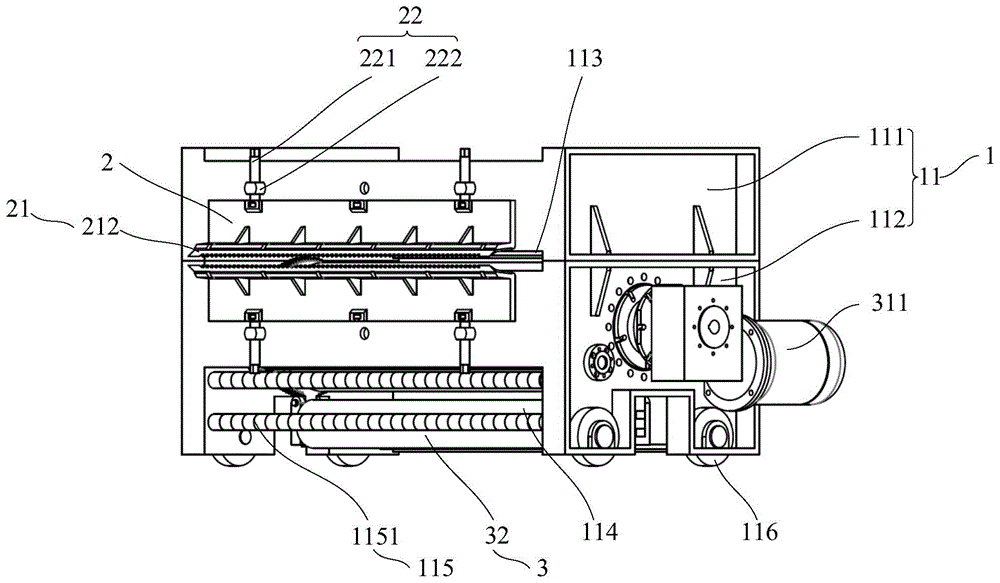
图1为本申请实施例提供的输送带钢丝绳芯分离装置的整体示意图;1 is an overall schematic diagram of a conveyor belt wire rope core separation device provided by an embodiment of the application;
图2为本申请实施例提供的输送带钢丝绳芯分离装置的切刀为平刀刃的三视图;FIG. 2 is a three-dimensional view of the cutter of the conveyor belt wire rope core separating device provided by the embodiment of the application being a flat blade;
图3为本申请实施例提供的输送带钢丝绳芯分离装置的切刀为成型刀刃的三视图;FIG. 3 is a three view of the cutting blade of the conveyor belt wire rope core separation device provided by the embodiment of the application as a forming blade;
图4为本申请实施例提供的输送带钢丝绳芯分离装置的横剖面示意图;4 is a schematic cross-sectional view of a conveyor belt wire rope core separation device provided in an embodiment of the application;
图5为本申请实施例提供的输送带钢丝绳芯分离装置的正视图;5 is a front view of a conveyor belt wire rope core separation device provided by an embodiment of the application;
图6为本申请实施例提供的输送带钢丝绳芯分离装置的输送带运动示意图;6 is a schematic diagram of the movement of the conveyor belt of the conveyor belt wire rope core separation device provided by the embodiment of the application;
图7为本申请实施例提供的输送带钢丝绳芯分离装置的压带辊传动机构局部示意图;Fig. 7 is a partial schematic diagram of the transmission mechanism of the pinch roller of the conveyor belt wire rope core separation device provided by the embodiment of the application;
图8为本申请实施例提供的输送带钢丝绳芯分离装置的压带辊传动机构A-A示意图;FIG. 8 is a schematic diagram of a belt pressing roller transmission mechanism A-A of a conveyor belt wire rope core separation device provided in an embodiment of the application;
图9为本申请实施例提供的输送带钢丝绳芯分离装置的运行示意图一;9 is a schematic diagram 1 of the operation of the conveyor belt wire rope core separation device provided by the embodiment of the application;
图10为本申请实施例提供的输送带钢丝绳芯分离装置的运行示意图二;Fig. 10 is a schematic diagram 2 of the operation of the conveyor belt wire rope core separation device provided by the embodiment of the application;
图11为本申请实施例提供的输送带钢丝绳芯分离装置的运行示意图三;Fig. 11 is a schematic diagram 3 of the operation of the conveyor belt wire rope core separation device provided by the embodiment of the application;
图12为本申请实施例提供的输送带钢丝绳芯分离装置的运行示意图四。FIG. 12 is a fourth schematic diagram of the operation of the device for separating the wire rope cores of the conveyor belt provided by the embodiment of the application.
附图标记:Reference number:
1-安装座;11-箱体;111-上箱体;112-下箱体;113-第一开口;114-第二开口;115-导向组件;1151-导向部;1152-导向轴;116-移动轮;2-切割机构;21-切刀;211-平刀刃;212-成型刀刃;22-调整组件;221-调整螺杆;222-调整螺母;3-输送机构;31-滚筒;311-第一驱动部;32-压带辊;321-第二驱动部;322-传动机构;3221-主动齿轮;3222-从动齿轮;3223-凸起结构;323-同步轴。1-installation seat; 11-box body; 111-upper box body; 112-lower box body; 113-first opening; 114-second opening; 115-guide assembly; 1151-guide part; 1152-guide shaft; 116 - moving wheel; 2- cutting mechanism; 21 - cutter; 211 - flat blade; 212 - forming blade; 22 - adjusting component; 221 - adjusting screw; 222 - adjusting nut; 3 - conveying mechanism; 31 - roller; 311 - 32-belt pressure roller; 321-second drive part; 322-transmission mechanism; 3221-drive gear; 3222-driven gear; 3223-protrusion structure; 323-synchronizing shaft.
具体实施方式Detailed ways
为使本申请实施例的目的、技术方案和优点更加清楚,下面将结合本申请实施例中的附图,对本申请的具体技术方案做进一步详细描述。以下实施例用于说明本申请,但不用来限制本申请的范围。In order to make the purposes, technical solutions and advantages of the embodiments of the present application more clear, the specific technical solutions of the present application will be described in further detail below with reference to the accompanying drawings in the embodiments of the present application. The following examples are used to illustrate the present application, but are not intended to limit the scope of the present application.
在本申请实施例中,术语“第一”、“第二”仅用于描述目的,而不能理解为指示或暗示相对重要性或者隐含指明所指示的技术特征的数量。由此,限定有“第一”、“第二”的特征可以明示或者隐含地包括一个或者更多个该特征。在本申请实施例的描述中,除非另有说明,“多个”的含义是两个或两个以上。In the embodiments of the present application, the terms "first" and "second" are only used for description purposes, and cannot be understood as indicating or implying relative importance or implying the number of indicated technical features. Thus, a feature defined as "first", "second" may expressly or implicitly include one or more of that feature. In the description of the embodiments of the present application, unless otherwise specified, "plurality" means two or more.
此外,在本申请实施例中,“上”、“下”、“左”以及“右”等方位术语是相对于附图中的部件示意置放的方位来定义的,应当理解到,这些方向性术语是相对的概念,它们用于相对于的描述和澄清,其可以根据附图中部件所放置的方位的变化而相应地发生变化。In addition, in the embodiments of the present application, orientation terms such as "upper", "lower", "left" and "right" are defined relative to the orientations in which the components in the drawings are schematically placed, and it should be understood that these orientations Sexual terms are relative concepts, they are used for relative description and clarification, which may vary according to the orientation in which components are placed in the figures.
在本申请实施例中,除非另有明确的规定和限定,术语“连接”应做广义理解,例如,“连接”可以是连接固定,也可以是可拆卸连接,或成一体;可以是直接相连,也可以通过中间媒介间接相连。In the embodiments of the present application, unless otherwise expressly specified and limited, the term "connection" should be understood in a broad sense. For example, "connection" may be a fixed connection, a detachable connection, or an integrated body; it may be directly connected , or indirectly through an intermediary.
在本申请实施例中,术语“包括”、“包含”或者其任何其他变体意在涵盖非排他性的包含,从而使得包括一系列要素的过程、方法、物品或者装置不仅包括那些要素,而且还包括没有明确列出的其他要素,或者是还包括为这种过程、方法、物品或者装置所固有的要素。在没有更多限制的情况下,由语句“包括一个……”限定的要素,并不排除在包括该要素的过程、方法、物品或者装置中还存在另外的相同要素。In the embodiments of the present application, the terms "comprising", "comprising" or any other variation thereof are intended to encompass non-exclusive inclusion, such that a process, method, article or device comprising a series of elements includes not only those elements, but also Include other elements not expressly listed, or which are inherent to such a process, method, article or apparatus. Without further limitation, an element qualified by the phrase "comprising a..." does not preclude the presence of additional identical elements in a process, method, article or apparatus that includes the element.
在本申请实施例中,“示例性的”或者“例如”等词用于表示作例子、例证或说明。本申请实施例中被描述为“示例性的”或者“例如”的任何实施例或设计方案不应被解释为比其他实施例或设计方案更优选或更具优势。确切而言,使用“示例性的”或者“例如”等词旨在以具体方式呈现相关概念。In the embodiments of the present application, words such as "exemplary" or "for example" are used to represent examples, illustrations or illustrations. Any embodiment or design described in the embodiments of the present application as "exemplary" or "such as" should not be construed as preferred or advantageous over other embodiments or designs. Rather, the use of words such as "exemplary" or "such as" is intended to present the related concepts in a specific manner.
本申请实施例提供了一种输送带钢丝绳芯分离装置,输送带钢丝绳芯分离装置适用于对输送带的接头进行硫化胶接的情形。在对输送带的接头进行硫化胶接之前需要对输送带接头的钢丝绳芯和胶质层进行分离,将输送带的钢丝绳芯周围的胶质层进行切除,使输送带的钢丝绳芯暴露出来,然后将输送带的钢丝绳芯搭接好,最后进行输送带接头的硫化胶接操作。The embodiment of the present application provides a conveyor belt wire rope core separation device, and the conveyor belt wire rope core separation device is suitable for the situation of vulcanizing and gluing the joints of the conveyor belt. Before vulcanizing and gluing the joint of the conveyor belt, it is necessary to separate the wire rope core and the colloidal layer of the conveyor belt joint, and cut off the colloidal layer around the wire rope core of the conveyor belt to expose the wire rope core of the conveyor belt. Lap the wire rope core of the conveyor belt well, and finally carry out the vulcanization bonding operation of the conveyor belt joint.
具体的,参照图1,本申请实施例提供的输送带钢丝绳芯分离装置包括:安装座1、切割机构2和输送机构3。其中,安装座1为输送带钢丝绳芯分离装置的其他机构提供安装基础;切割机构2连接至安装座1,在切割机构2上设置有切刀21,切刀21用于对输送带接头部位的钢丝绳芯进行分离,具体的,用于对输送带的钢丝绳芯周围的胶质层进行切除。切刀21沿输送带的宽度方向布置,并且切刀21沿输送带宽度方向的尺寸大于等于输送带的宽度;输送机构3与安装座1固定连接,用于使输送带接头部位沿切刀21运动。需要说明的是,这里所指的输送带接头部位,指输送带需要将钢丝绳芯和胶质层进行分离的部位,对于输送带接头的硫化胶接工作,输送带接头部位的长度需要根据输送带的材质以及输送带的使用载荷进行确定。在本申请实施例中,输送接接头部位的长度不特指某一长度,需根据输送带的材质以及输送带的使用载荷进行确定,本申请实施例不对此进行限定。Specifically, referring to FIG. 1 , the conveyor belt wire rope core separation device provided in the embodiment of the present application includes: a mounting
示例的,在本申请的一些实施例中,安装座1可以利用型钢材料进行制作。安装座1的形状可以为底座型,例如,可以利用槽钢焊接成一个底座,将切割机构2和输送机构3都安装在底座上。在本申请的另一些实施例中,也可以将安装座1制作成框架型,例如,可以利用槽钢焊接成框架型结构,将切割机构2和输送机构3都安装在框架内。在本申请的其他实施例中,参照图1,也可以将安装座1制作成箱体11,将切割机构2和输送机构3均安装在箱体11内,将安装座1设置成箱体11能够将箱体11内的空间与外部空间进行隔离,防止箱体11内的运动部件伤害到工作人员。对于安装座1的制作有多种选择,本申请实施例不对此进行限定。Illustratively, in some embodiments of the present application, the mounting
切割机构2连接至安装座1可以有多种连接方式,可以将切割机构2通过紧固件连接至安装座1,并且,通过紧固件连接,能够方便的对切割机构2进行更换或调整。也可以通过焊接连接的方式将切割机构2与安装座1连接在一起,焊接连接能够使切割机构2与安装座1的连接更牢固,但是不易于对切割机构2进行调整或保养。The
同时,在切割机构2上设置有切刀21,切刀21用于对输送带接头部位的钢丝绳芯进行分离。本申请实施例也不对切割机构2的形式进行限定,只要是能够将切刀21连接在切割机构2上,同时又能将切割机构2连接至安装座1上即可。例如,切割机构2可以为钢板结构,钢板的一端安装切刀21,钢板的另一端连接至安装座1。也可以参照图1,将切割机构2设置成角铁结构,角铁结构的一端连接切刀21,另一端活动连接至安装座1,同时,为了提高切割机构2的受力强度,在角铁结构的折角处还设置有肋板。At the same time, a
需要说明的是,切刀21与切割机构2的连接也有多种实现方式,例如,可以将切刀21卡接在切割机构2上;也可以通过紧固件将切刀21连接至切割机构2上,本申请实施例不对此进行限定。It should be noted that the connection between the cutting
同时,将切刀21沿输送带的宽度方向进行布置,即,切刀21的延伸方向与输送带的延伸方向垂直,也即与输送带的长度方向垂直,这样能充分发挥切刀21的作用,能使切刀21切割的面积最大。进一步的,切刀21沿输送带宽度方向的尺寸大于等于输送带的宽度。这样能提高切刀21的切割效率,一次切割就可以将整个输送带宽度方向的胶质层进行切除,从而提高了本申请实施例提供的输送带钢丝绳芯分离装置的作业效率,解决了输送带钢丝绳芯分离工作的劳动强度大、耗时长的问题。At the same time, the
另外,本申请实施例提供的输送带钢丝绳芯分离装置的输送机构3与安装座1固定连接,输送机构3用于驱动输送带运动,从而使输送带接头部位沿切刀21运动。通过设置输送机构3能够使本申请实施例提供的输送带钢丝绳芯分离装置尽量多的使用机械代替人工,进一步的提高了对输送带钢丝绳芯分离的作业效率。In addition, the conveying
输送机构3的设置也有多种选择,例如,在本申请的一些实施例中,在输送带接头的端部设置牵引装置,通过电动机牵引输送带,使输送带接头部位沿切刀21运动,从而使切刀21切割输送带接头部位,实现切刀21对输送带接头部位的钢丝绳芯进行分离的目的。在本申请的另一些实施例中,也可以使用滚筒31,利用滚筒31与输送带的摩擦力使输送带随着滚筒31的旋转而进行运动,从而使输送带接头部位沿切刀21运动,实现切刀21对输送带接头部位的钢丝绳芯进行分离的目的。There are also various options for the setting of the
在此基础上,参照图2和图3,本申请实施例提供的输送带分离装置的切刀21的刀刃有两种,分别为平刀刃211和成型刀刃212。参照图2,平刀刃211的刃口呈现直线型,类似于常用的刀具,平刀刃211用于沿输送带延伸方向上将输送带的胶质层和钢丝绳芯进行分离。进一步的,参照图3,成型刀刃212上排列布置有多个半圆形刃口,用于沿输送带延伸方向的垂直方向上将输送带的胶质层和钢丝绳芯进行分离,也即沿输送带的长度方向上将输送带的胶质层进行切除,使输送带的钢丝绳芯和胶质层进行分离。示例的,当将平刀刃211布置在输送带接头部位的上表面,并将平刀刃211伸入输送带内部,紧贴输送带钢丝绳芯的上侧,这时,通过输送机构3使输送带接头部位相对于平刀刃211运动,可以使平刀刃211将输送带钢丝绳芯上方的胶质层切除掉,当在输送带的上表面和下表面均布置平刀刃211时,可以一次将输送带钢丝绳芯上方和下方的胶质层进行切除。然后利用成型刀刃212将输送带接头部位的钢丝绳芯之间的胶质层进行切除,由于输送带的钢丝绳芯是沿输送带的延伸方向延伸的,且多根钢丝绳是沿输送带的宽度方向排列的,成型刀刃212就是沿输送带宽度方向将钢丝绳芯之间的胶质层进行切除,具体如下:将成型刀刃212的半圆形刃口与输送带的钢丝绳芯配合安装,使半圆形刃口紧贴钢丝绳芯的外缘,然后通过输送机构3使输送带接头部位相对于成型刀刃212运动,这样可以使使成型刀刃212将输送带接头部位的钢丝绳芯之间的胶质层切除掉,当在输送带的上表面和下表面均布置成型刀刃212时,使两个成型刀刃212之间的半圆形刃口对应钢丝绳芯进行设置,这样可以一次将输送带钢丝绳芯之间的胶质层进行切除。On this basis, referring to FIGS. 2 and 3 , the
在此基础上,参照图3,成型刀刃212的半圆形刃口的直径等于输送带钢丝绳芯的直径。并且,多个半圆形刃口之间的间距等于输送带钢丝绳芯之间的间距。通过将半圆形刃口的直径与输送带钢丝绳芯的直径设置的相等,可以有效的将输送带钢丝绳芯外的胶质层进行切除,保证对输送带钢丝绳芯附近的胶质层的切除的质量。并且将多个半圆形刃口之间的间距设置的与输送带钢丝绳芯之间的间距相等,可以一次将沿输送带宽度方向将输送带钢丝绳芯之间的胶质层进行切除。On this basis, referring to FIG. 3 , the diameter of the semicircular cutting edge of the forming
进一步的,参照图4,在本申请的一些实施例中,输送带钢丝绳芯分离装置的切刀21的刃口的尖端朝向对输送带接头部位的钢丝绳芯进行分离时的输送带接头部位的一侧倾斜。具体的,可以使切割机构2安装切刀21的位置倾斜一定的角度,并且倾斜的方向与切刀21的朝向一致,这样能够使切刀21的刀刃的尖端朝向对输送带接头部位的钢丝绳芯进行分离时的输送带接头部位的一侧倾斜。Further, referring to FIG. 4 , in some embodiments of the present application, the tip of the cutting edge of the
同时,参照图2和图3,也可以将切刀21的刀刃设置成一定的角度,这样也能够使切刀21的刀刃的尖端朝向对输送带接头部位的钢丝绳芯进行分离时的输送带接头部位的一侧倾斜。这也相当于,切刀21的刀刃的延伸方向与输送带之间具有一个夹角,并且,切刀21的刀刃的延伸方向与切刀21对输送带的胶质层进行切割时输送带的运动方向相逆。At the same time, referring to Fig. 2 and Fig. 3 , the blade of the
为了方便对本申请实施例提供的输送带钢丝绳芯分离装置进行组装或检修,参照图1和图4,在本申请的一些实施例中,将安装座1设置为箱体11,包括上箱体111和下箱体112。并且,上箱体111和下箱体112可拆卸的连接在一起,这样能够方便对箱体11内的机构进行组装或检修。同时,为了方便对切割机构2和输送机构3进行布置,以及考虑到输送带的运动,将切割机构2设置在上箱体111和下箱体112的连接处,将输送机构3设置在下箱体112内。参照图1,为了加强箱体11的强度,在上箱体111和下箱体112的结合面附近还设置有加强肋板,这样能提高本申请实施例提供的输送带钢丝绳芯分离装置的整体强度,能够防止输送带钢丝绳芯分离装置变形。In order to facilitate the assembly or maintenance of the conveyor belt wire rope core separation device provided in the embodiments of the present application, referring to FIG. 1 and FIG. 4 , in some embodiments of the present application, the mounting
在此基础上,参照图1和图4,上箱体111和下箱体112的连接处设置有第一开口113,切割机构2就设置在第一开口113处,并且切刀21的延伸方向与第一开口113的延伸方向平行。具体的,为了设置第一开口113,可以在上箱体111靠近下箱体112的侧面的边缘设置缺口结构,同时,在下箱体112对应位置设置缺口结构,这样,将上箱体111和下箱体112连接完成后,上箱体111和下箱体112之间的缺口结构形成第一开口113。同时,为了对切割机构2形成支撑,在上箱体111和下箱体112靠近第一开口113附近利用钢板焊接形成加强结构,从而进一步提高第一开口113附近的箱体11的受力强度。On this basis, referring to FIGS. 1 and 4 , a
进一步的,在本申请的一些实施例中,参照图1和图4,切割机构2为两个,分别布置在第一开口113的两侧,并且两个切割机构2的切刀21的刀刃相向布置,分别对应输送带的上下表面,输送机构3能够使输送带接头部位在两个切刀之间运动,当输送带的接头部位在两个切刀21之间运动时,两个切刀21可以同时切除输送带上下两侧的胶质层。通过这样设置,进一步的提高了本申请实施例提供的输送带钢丝绳芯分离装置对输送带钢丝绳芯分离的作业效率。Further, in some embodiments of the present application, referring to FIGS. 1 and 4 , there are two cutting
另外,参照图1和图4,在切割机构2和箱体11之间还设置有调整组件22,调整组件22与箱体11活动连接,调整组件22能够使切割机构2垂直于第一开口113在箱体11上滑动,并且调整装置还可以使切割机构2锁止在目标位置。In addition, referring to FIGS. 1 and 4 , between the
在本申请的一些实施例中,调整组件22可以为紧固件,具体的,可以在箱体11或切割机构2上沿第一开口113的垂直方向开设长条孔,将切割机构2调整好位置后,将紧固件进行紧固,可以将切割机构2锁止在目标位置。In some embodiments of the present application, the
在本申请的另一些实施例中,参照图1和图4,调整装置为调整螺杆221,调整螺杆221与切割机构2活动连接,以使调整螺杆221能够相对切割机构2旋转。In other embodiments of the present application, referring to FIGS. 1 and 4 , the adjusting device is an adjusting
需要说明的是,调整螺杆221与切割机构2的活动连接的实现方式有多种,在本申请的一些实施例中,可以通过在切割机构2上设置球形的孔洞结构,在调整螺杆221对应的端部设置对应的球形凸起,将调整螺杆221端部的球形凸起卡入切割机构2上的球形孔洞内,这样可以使调整螺杆221与切割机构2保持连接,并且使调整螺杆221相对切割机构2能够旋转。It should be noted that there are various ways to realize the movable connection between the adjusting
在本申请的另一些实施例中,参照图5,也可以将上述的球形卡接替换为图5中所示的圆柱形卡接结构,在调整螺杆221的端部设置有外大内小的圆柱台,对应的在切割机构2上设置有外小内大的圆柱槽,通过将调整螺杆221端部的圆柱台与切割机构2上的圆柱槽进行卡接,可以使调整螺杆221与切割机构2保持连接,并且使调整螺杆221相对切割机构2能够旋转。In other embodiments of the present application, referring to FIG. 5 , the above-mentioned spherical snap connection can also be replaced with the cylindrical snap connection structure shown in FIG. The cylindrical table corresponds to a cylindrical groove with a small outer and a large inner on the
在箱体11上对应调整螺杆221设置有调整螺母222,调整螺母222与箱体11固定连接。通过调整螺杆221与调整螺母222的配合安装,将调整螺杆221沿调整螺母222旋转,可以改变调整螺杆221的位置,从而可以驱动切割机构2沿箱体11滑动,可以改变切割机构2的位置。并且,调整螺杆221与调整螺母222之间的螺纹配合具有自锁功能,可以将切割机构2锁止在目标位置。An
这样,通过调整第一开口113两侧的切割机构2的位置,进而也调整了两侧的切割机构2上的切刀21的位置,也实现了对两侧切刀21的间隙进行调整的目的。可以根据输送带的位置适应性的将切刀21的位置进行调整,这样可以保证输送带在切刀21处的运动方向呈直线,减小输送带在运动时对切刀21的冲击。同时,通过调整切刀21之间的间隙,也能使本申请实施例提供的输送带钢丝绳芯分离装置能够用于不同厚度的输送带。在使用平刀刃211的切刀21时,通过调整切刀21的位置,使切刀21的刀刃在输送带钢丝绳芯的边缘,可以一次将输送带钢丝绳芯两侧的胶质层进行切除;在使用成型刀刃212的切刀21时,通过调整切刀21的位置,可以一次将输送带钢丝绳芯之间的胶质层进行切除。In this way, by adjusting the positions of the cutting
进一步的,参照图1和图5,在本申请的一些实施例中,在箱体11的下箱体112上还设置有第二开口114,第二开口114与第一开口113平行设置,并且,第二开口114和第一开口113的中心线重合,输送机构3能够使输送带沿第一开口113和第二开口114运动。具体的,在对输送带进行钢丝绳芯分离作业时,输送带接头部位从第二开口114进入箱体11内部,然后经输送机构3将输送带接头部位运送至第一开口113处,并且使输送带接头部位完全伸出第一开口113外,继而调整切刀21的位置,然后使输送机构3反转,从而使输送带接头部位沿着切刀21运动,实现切刀21对输送带接头部位的胶质层的切割。Further, referring to FIG. 1 and FIG. 5 , in some embodiments of the present application, a
示例的,参照图6,为本申请实施例提供的输送带钢丝绳芯分离装置利用平切刀21对输送带接头部位的钢丝绳芯进行分离的示意图。By way of example, referring to FIG. 6 , it is a schematic diagram of the conveyor belt wire rope core separation device provided in the embodiment of the present application using the
另外,参照图1和图4,在箱体11内靠近第二开口114处还设置有导向组件115,导向组件115上设置有导向部1151,导向部1151可沿自身轴线进行旋转,用于对输送带进行导向。在输送机构3运转过程中,会使输送带出现张紧或松弛状态,特别是输送带分离装置启动或停止的瞬间,会使输送带有较大的波动,可能会使输送带会与第二开口114附近的尖锐部位碰撞,会损伤输送带,设置导向组件115能够避免此种情形的发生。导向组件115的设置方式也有多种,示例的,参照图1和图4,在本申请的一些实施例中,可以在第二开口114的两侧各设置一根导向轴1152,然后在导向轴1152上排列设置多个导向部1151,导向部1151通过滚动轴承与导向轴1152连接,从而使导向部1151可相对自身轴线进行旋转,这样,输送带可以沿导向部1151运动,并且输送带与导向组件115之间的摩擦为滚动摩擦,大大减小了输送带与导向组件115之间的摩擦力;在本申请的另一些实施例中,可以在导向轴1152上套设一个钢管,钢管通过滚动轴承与导向轴1152连接,从而使钢管可相对自身轴线进行旋转。In addition, referring to FIGS. 1 and 4 , a
具体的,参照图4和图6,本申请实施例提供的输送带钢丝绳芯分离装置的输送机构3包括滚筒31,并且滚筒31设置在下箱体112内,滚筒31的旋转轴线平行于第一开口113。同时,在箱体11外对应滚筒31设置有第一驱动部311,第一驱动部311用于驱动滚筒31转动。Specifically, referring to FIG. 4 and FIG. 6 , the conveying
在本申请的一些实施例中,第一驱动部311为电动机,一般的电动机转速高,扭矩小,可以通过增设减速箱,将减速箱的输入端连接至电动机,将减速箱的输出端连接至滚筒31,这样能够使减速箱输出端的转速降低、扭矩增加,更适合本申请实施例提供的输送带钢丝绳芯分离装置的使用要求。In some embodiments of the present application, the
在本申请的另一些实施例中,第一驱动部311为液压马达,液压马达的驱动介质为液压油,通过调整液压油的参数可以方便的调整液压马达的运行参数,从而调整液压马达的转速和扭矩,使液压马达的运行参数满足本申请实施例提供的输送带钢丝绳芯分离装置的使用要求。In other embodiments of the present application, the
在滚筒31运行过程中,由于滚筒31与输送带的摩擦力的作用,滚筒31会驱动输送带一起运动,进而可以使输送带接头部位相对切刀21进行运动。通过对滚筒31进行合适的设置,可以增加滚筒31与输送带之间的摩擦力,例如,可以在滚筒31的表面设置凸点,或者在滚筒31的表面镶镀一层橡胶或其他摩擦系数大的材质,这样能够防止输送带打滑,提高滚筒31与输送带之间的传动效率。During the operation of the
进一步的,参照图4和图6,在本申请的一些实施例中,为了增加输送带对滚筒31的压力,从而增加滚筒31与输送带之间的摩擦力,输送机构3还包括压带辊32。具体的,压带辊32平行于滚筒31设置在下箱体112内,并且,压带辊32的直径小于滚筒31的直径,在压带辊32与滚筒31之间存在小于输送带厚度的间隙,这样压带辊能够将输送带压紧在滚筒31的表面,增加输送带与滚筒31之间的压力,增大输送带与滚筒31的摩擦力。Further, referring to FIG. 4 and FIG. 6 , in some embodiments of the present application, in order to increase the pressure of the conveyor belt on the
同时,压带辊32还可以沿自身的轴线进行旋转,这样,输送带在运动过程中,压带辊32可以随着输送带的运动而进行旋转,使输送带与压带辊32之间摩擦为滚动摩擦,从而使压带辊32和输送带之间的摩擦力减小。At the same time, the
需要说明的是,压带辊32的设置也有多种方式,例如可以在压带辊32的中间设置一个转动轴,在转动轴的外部套设一个钢管,钢管与转动轴之间通过滚动轴承连接;也可以利用滚轮替换钢管,将多个滚轮排列布置设置在转动轴上,从而也可以形成压带辊32。It should be noted that there are also many ways to set the
参照图5,在箱体11外对应压带辊32还设置有第二驱动部321。参照图7,并且在第二驱动部321和压带辊32之间还设置有传动机构322,第二驱动部321通过传动机构322驱动压带辊32绕滚筒31旋转,并且,通过控制第二驱动部321的运动参数,可以使压带辊32绕滚筒31在滚筒31的正上方和正下方之间转动。具体的,可以通过控制第二驱动部321的启动、停止或改变第二驱动部321的转向来控制压带辊32的运动。Referring to FIG. 5 , a
类似的,第二驱动部321也可以选择电动机或液压马达,本申请实施例不对此进行限定。另外,第二驱动部321和压带辊32之间传动机构322可以设置成皮带进行传动,也可以设置成链条进行传动,本申请实施例不对此进行限定。Similarly, the
示例的,参照图7和图8,在本申请的一些实施例中,第二驱动部321和压带辊32之间通过齿轮机构进行传动。For example, referring to FIGS. 7 and 8 , in some embodiments of the present application, the transmission between the
具体的,传动机构322包括主动齿轮3221和从动齿轮3222,主动齿轮3221设置在第二驱动部321上,从动齿轮3222与滚筒31同轴设置,并且可以绕滚筒31同轴旋转。如图所示,主动齿轮3221和从动齿轮3222通过外啮合传动连接。Specifically, the
另外,压带辊32连接至从动齿轮3222,当第二驱动部321驱动主动齿轮3221和从动齿轮3222旋转时,从动齿轮3222能够带动压带辊32绕滚筒31转动。In addition, the
需要说明的是,压带辊32与从动齿轮3222的连接,可以通过紧固件连接、焊接、卡接等连接方式,本申请实施例不对此进行限定。It should be noted that, the connection between the
另外,参照图7和图8,可以在从动齿轮3222和滚筒31之间设置滚动轴承来实现从动齿轮3222可绕滚筒31进行旋转;也可以在从动齿轮3222和滚筒31之间设置滑动轴承来实现从动齿轮3222绕滚筒31进行旋转,本申请实施例不对此进行限定。In addition, referring to FIGS. 7 and 8 , a rolling bearing can be provided between the driven
对于第二驱动部321为电动机的情形,还可以在电动机的输出轴上设置减速箱来降低输出速度、提高输出扭矩,这时,可以将主动齿轮3221设置在减速箱的输出轴上。In the case where the
参照图8,在本申请的一些实施例中,在从动齿轮3222上设置有沿其径向延伸的凸起结构3223,压带辊32连接至该凸起结构3223。这样能够使从动齿轮3222和压带辊32的连接简单,并且,凸起结构3223与从动齿轮3222为一个整体,从而使凸起结构3223具有较大的受力强度。Referring to FIG. 8 , in some embodiments of the present application, the driven
此外,参照图6,为了使压带辊32的运动路径与主动齿轮3221不干涉,并且能够使压带辊32沿输送带的运动路径运动,在本申请的一些实施例中,主动齿轮3221和压带辊32设置在输送带运动路径的两侧。具体的,主动齿轮3221和滚筒31设置在输送带运动路径的同一侧,压带辊32设置在输送带运动路径的另一侧。In addition, referring to FIG. 6 , in order to prevent the movement path of the
进一步的,参照图7,为了使压带辊32的运动平稳,在本申请的一些实施例中,从动齿轮3222的数量为两个,分别设置在滚筒31的两端,压带辊32则设置在两个从动齿轮3222之间。Further, referring to FIG. 7 , in order to make the movement of the
在此基础上,参照图7,主动齿轮3221的数量也为两个,分别对应两个从动齿轮3222设置,并且两个主动齿轮3221共用一个第二驱动部321,为了实现两个从动齿轮3222之间的传动,两个主动齿轮3221通过同步轴323连接在一起。当靠近第二驱动部321的主动齿轮3221旋转时,同步轴323能够使另一个主动齿轮3221跟随旋转,从而使两个从动齿轮3222能够同步旋转,进而使本申请实施例提供的输送带钢丝绳芯分离装置的压带辊32的转动稳定、可靠。On this basis, referring to FIG. 7 , the number of driving gears 3221 is also two, which are respectively provided corresponding to the two driven
另外,参照图1、图4和图6,在本申请的一些实施例中,在箱体11的下端还设置有移动轮116,通过移动轮116能够方便的将本申请实施例提供的输送带钢丝绳芯分离装置进行移位。In addition, referring to FIG. 1 , FIG. 4 and FIG. 6 , in some embodiments of the present application, a moving
需要说明的是,参照图9~图12,下面对本申请实施例提供的输送带钢丝绳芯分离装置的整个运动过程进行简单说明。It should be noted that, referring to FIG. 9 to FIG. 12 , the entire movement process of the conveyor belt wire rope core separation device provided in the embodiment of the present application will be briefly described below.
具体的,参照图9,在本申请实施例提供的输送带钢丝绳芯分离装置的初始阶段,输送带接头部位经导向组件115伸入压带辊32和滚筒31之间,此时启动第一驱动部311和第二驱动部321,使滚筒31和压带辊32按照图中箭头所示方向进行旋转,同时带动输送带跟随同步运动,到达如图10中所示位置。Specifically, referring to FIG. 9 , in the initial stage of the conveyor belt wire rope core separation device provided by the embodiment of the present application, the conveyor belt joint part extends between the
参照图10,使第一驱动部311和第二驱动部321继续运行,使滚筒31和压带辊32继续按照图中箭头所示方向继续进行旋转,带动输送带跟随同步运动到达如图11中所示位置。Referring to FIG. 10 , the
参照图11,当压带辊32位于滚筒31的正上方时,停止第二驱动部321,压带辊32不再继续绕滚筒31进行转动。需要说明的是,此时第一驱动部311仍继续保持运行,使输送带继续朝向切刀21运动。此时,由于输送带的摩擦力,压带辊32绕自身轴线进行旋转。11 , when the
参照图12,此时输送带接头部位全部伸出切刀21,这时,停止第一驱动部311的运行。Referring to FIG. 12 , at this time, all the joint parts of the conveyor belt extend out of the
首先利用平刀刃211的切刀21对输送带上下两侧的胶质层进行切除,调整平刀刃211的切刀21的位置,使上下两个平刀刃211的切刀21之间的间隙等于输送带钢丝绳芯的直径。First, use the
具体的,启动第二驱动部321,并使第二驱动部321运行方向与上述步骤的运行方向相反,使压带辊32按照图中箭头所示方向进行旋转,使压带辊32回到图9中位置,停止第二驱动部321。然后,启动第一驱动部311,并使第一驱动部311的运行方向与上述步骤的运行方向相反,使输送带朝着第二开口114的方向运行,这样平刀刃211的切刀21就完成了对输送带接头部位的钢丝绳芯上下两侧的胶质层进行切除的工作,可参照图6。将平刀刃211的切刀21更换为成型刀刃212的切刀21,重复上述步骤,即可完成对输送带接头部位的钢丝绳芯之间的胶质层进行切除的工作,从而完成对输送带接头部位的钢丝绳芯分离工作。Specifically, the
上述本申请实施例序号仅仅为了描述,不代表实施例的优劣。以上仅为本申请的优选实施例,并非因此限制本申请的专利范围,凡是利用本申请说明书及附图内容所作的等效结构或等效流程变换,或直接或间接运用在其他相关的技术领域,均同理包括在本申请的专利保护范围内。The above-mentioned serial numbers of the embodiments of the present application are only for description, and do not represent the advantages or disadvantages of the embodiments. The above are only the preferred embodiments of the present application, and are not intended to limit the patent scope of the present application. Any equivalent structure or equivalent process transformation made by using the contents of the description and drawings of the present application, or directly or indirectly applied in other related technical fields , are similarly included within the scope of patent protection of this application.
Claims (19)
Priority Applications (4)
| Application Number | Priority Date | Filing Date | Title |
|---|---|---|---|
| CN202210745326.1A CN115179357B (en) | 2022-06-27 | 2022-06-27 | Conveyer belt steel wire rope core separating device |
| PCT/CN2022/138779 WO2024001064A1 (en) | 2022-06-27 | 2022-12-13 | System and apparatus for rubber and core separation operation before vulcanization of strong conveyor belt joint |
| US18/553,565 US20250073942A1 (en) | 2022-06-27 | 2022-12-13 | Glue-core separation operation system and equipment for separating glue-core of conveyor belt joint before vulcanization |
| AU2022442098A AU2022442098B2 (en) | 2022-06-27 | 2022-12-13 | Glue-core separation operation system and equipment for separating glue-core of conveyor belt joint before vulcanization |
Applications Claiming Priority (1)
| Application Number | Priority Date | Filing Date | Title |
|---|---|---|---|
| CN202210745326.1A CN115179357B (en) | 2022-06-27 | 2022-06-27 | Conveyer belt steel wire rope core separating device |
Publications (2)
| Publication Number | Publication Date |
|---|---|
| CN115179357A true CN115179357A (en) | 2022-10-14 |
| CN115179357B CN115179357B (en) | 2024-06-25 |
Family
ID=83514526
Family Applications (1)
| Application Number | Title | Priority Date | Filing Date |
|---|---|---|---|
| CN202210745326.1A Active CN115179357B (en) | 2022-06-27 | 2022-06-27 | Conveyer belt steel wire rope core separating device |
Country Status (4)
| Country | Link |
|---|---|
| US (1) | US20250073942A1 (en) |
| CN (1) | CN115179357B (en) |
| AU (1) | AU2022442098B2 (en) |
| WO (1) | WO2024001064A1 (en) |
Cited By (3)
| Publication number | Priority date | Publication date | Assignee | Title |
|---|---|---|---|---|
| WO2024001064A1 (en) * | 2022-06-27 | 2024-01-04 | 太原理工大学 | System and apparatus for rubber and core separation operation before vulcanization of strong conveyor belt joint |
| CN119658871A (en) * | 2024-12-31 | 2025-03-21 | 太原理工大学 | Separation device and separation method |
| US20250269548A1 (en) * | 2024-02-26 | 2025-08-28 | Taiyuan University Of Technology | Split-type device for continuously and rapidly separating steel cord belt |
Citations (5)
| Publication number | Priority date | Publication date | Assignee | Title |
|---|---|---|---|---|
| US20060070504A1 (en) * | 2004-10-01 | 2006-04-06 | Downing Daniel R | Apparatus for cutting elastomeric materials |
| CN105856800A (en) * | 2016-06-02 | 2016-08-17 | 张家港市华申工业橡塑制品有限公司 | Pulling machine for reproducing waste conveying belt |
| CN109968682A (en) * | 2019-05-05 | 2019-07-05 | 辽宁工程技术大学 | Multi-drive glue removal device and method for conveyor belt joint cover glue and steel wire rope core glue |
| CN111604989A (en) * | 2020-06-04 | 2020-09-01 | 郭磊 | Quick rubber cutting machine for processing rubber functional material products |
| CN213194707U (en) * | 2020-09-24 | 2021-05-14 | 池州市东聚新能源科技有限公司 | A PET film degumming machine |
Family Cites Families (10)
| Publication number | Priority date | Publication date | Assignee | Title |
|---|---|---|---|---|
| DE2138132C2 (en) * | 1971-07-30 | 1973-10-31 | Rheinische Braunkohlenwerke Ag, 5000 Koeln | Method and profile strip for joining strips of tape |
| CA2115183A1 (en) * | 1993-02-12 | 1994-08-13 | Takashi Nomoto | Substituted amic acid derivatives |
| JP4011776B2 (en) * | 1999-02-05 | 2007-11-21 | バンドー化学株式会社 | Method and apparatus for processing used ST conveyor belt |
| CN101245826B (en) * | 2007-10-16 | 2010-08-04 | 上海高罗输送装备有限公司 | Conveyer belt rubber stripping machine |
| JP5455207B2 (en) * | 2009-08-25 | 2014-03-26 | 株式会社ブリヂストン | Rubber cutting device for conveyor belt and rubber cutting method |
| CN103640322B (en) * | 2013-11-06 | 2015-09-16 | 中国电器科学研究院有限公司 | A kind of device for scraping of scrap rubber conveyer belt scrap rubber layer and method |
| US9881718B2 (en) * | 2014-03-21 | 2018-01-30 | Quanta Associates, L.P. | Method and apparatus for continuously processing conductor cable for disposal or recycling |
| CN111605203A (en) * | 2020-06-13 | 2020-09-01 | 台州市铭通机械股份有限公司 | A stripping machine for wire rope conveyor belts |
| CN214002995U (en) * | 2020-12-08 | 2021-08-20 | 唐山滦科机电设备制造有限公司 | Steel wire rope conveying belt peeling machine |
| CN115179357B (en) * | 2022-06-27 | 2024-06-25 | 太原理工大学 | Conveyer belt steel wire rope core separating device |
-
2022
- 2022-06-27 CN CN202210745326.1A patent/CN115179357B/en active Active
- 2022-12-13 WO PCT/CN2022/138779 patent/WO2024001064A1/en not_active Ceased
- 2022-12-13 AU AU2022442098A patent/AU2022442098B2/en active Active
- 2022-12-13 US US18/553,565 patent/US20250073942A1/en active Pending
Patent Citations (5)
| Publication number | Priority date | Publication date | Assignee | Title |
|---|---|---|---|---|
| US20060070504A1 (en) * | 2004-10-01 | 2006-04-06 | Downing Daniel R | Apparatus for cutting elastomeric materials |
| CN105856800A (en) * | 2016-06-02 | 2016-08-17 | 张家港市华申工业橡塑制品有限公司 | Pulling machine for reproducing waste conveying belt |
| CN109968682A (en) * | 2019-05-05 | 2019-07-05 | 辽宁工程技术大学 | Multi-drive glue removal device and method for conveyor belt joint cover glue and steel wire rope core glue |
| CN111604989A (en) * | 2020-06-04 | 2020-09-01 | 郭磊 | Quick rubber cutting machine for processing rubber functional material products |
| CN213194707U (en) * | 2020-09-24 | 2021-05-14 | 池州市东聚新能源科技有限公司 | A PET film degumming machine |
Cited By (3)
| Publication number | Priority date | Publication date | Assignee | Title |
|---|---|---|---|---|
| WO2024001064A1 (en) * | 2022-06-27 | 2024-01-04 | 太原理工大学 | System and apparatus for rubber and core separation operation before vulcanization of strong conveyor belt joint |
| US20250269548A1 (en) * | 2024-02-26 | 2025-08-28 | Taiyuan University Of Technology | Split-type device for continuously and rapidly separating steel cord belt |
| CN119658871A (en) * | 2024-12-31 | 2025-03-21 | 太原理工大学 | Separation device and separation method |
Also Published As
| Publication number | Publication date |
|---|---|
| AU2022442098A1 (en) | 2024-01-18 |
| WO2024001064A1 (en) | 2024-01-04 |
| AU2022442098B2 (en) | 2024-11-21 |
| CN115179357B (en) | 2024-06-25 |
| US20250073942A1 (en) | 2025-03-06 |
Similar Documents
| Publication | Publication Date | Title |
|---|---|---|
| CN115179357A (en) | Steel wire rope core separation device for conveying belt | |
| CN101171123B (en) | Method and apparatus for producing paper tube having polygonal cross section, and paper tube manufactured by the method | |
| CN106429177B (en) | Belt changing device of belt conveyor | |
| US8307683B2 (en) | Apparatus for manufacturing coil spring | |
| CN110589593B (en) | Automatic double faced adhesive tape pasting mechanism on arc-shaped surface | |
| US20250375913A1 (en) | Technique and process for separating rubber from core before vulcanization of strong conveyor belt joint | |
| CN110550270B (en) | Roller packaging machine | |
| US10328652B2 (en) | Strip-winding method and strip-winding apparatus | |
| WO2023169070A1 (en) | Apparatus for paperboard-film lamination | |
| CN213264934U (en) | Device for controlling tension during production of flexible material | |
| CN206425879U (en) | Bar material transfer structure | |
| CN111532861B (en) | Device for controlling tension in flexible material production | |
| KR100998761B1 (en) | Steel Belt Zipping Device | |
| CN223733087U (en) | High-efficient automatic mark of weaving and leather combination's oily limit machine | |
| CN207631621U (en) | The manufacturing system for merging shear and radial of multi-layer packaging paper | |
| CN107984807A (en) | A kind of corrugated paper organisation of working of Corrugating Machine | |
| CN218114121U (en) | A guide device for the output channel of the finished product of the box | |
| CN222808436U (en) | Packaging film cutting assembly for cable packaging film winding machine | |
| CN223467987U (en) | A strip guiding device for a slitting machine | |
| CN119460837B (en) | Coiling mechanism and pole piece roll-in equipment | |
| CN222138288U (en) | A new gluing mechanism for paper box processing | |
| CN223719608U (en) | High-speed edging machine for heterojunction | |
| KR101692750B1 (en) | Apparatus for winding tape to cable | |
| CN221974212U (en) | A guide column type tensioner assembly | |
| CN216945585U (en) | Single face corrugated paper is positioner for cross cutting |
Legal Events
| Date | Code | Title | Description |
|---|---|---|---|
| PB01 | Publication | ||
| PB01 | Publication | ||
| SE01 | Entry into force of request for substantive examination | ||
| SE01 | Entry into force of request for substantive examination | ||
| GR01 | Patent grant | ||
| GR01 | Patent grant |