CN115225746A - Electronic equipment - Google Patents

Electronic equipment Download PDF

Info

Publication number
CN115225746A
CN115225746A CN202211148894.XA CN202211148894A CN115225746A CN 115225746 A CN115225746 A CN 115225746A CN 202211148894 A CN202211148894 A CN 202211148894A CN 115225746 A CN115225746 A CN 115225746A
Authority
CN
China
Prior art keywords
groove
hole
sound
electronic device
speaker
Prior art date
Legal status (The legal status is an assumption and is not a legal conclusion. Google has not performed a legal analysis and makes no representation as to the accuracy of the status listed.)
Granted
Application number
CN202211148894.XA
Other languages
Chinese (zh)
Other versions
CN115225746B (en
Inventor
吴江
王传果
Current Assignee (The listed assignees may be inaccurate. Google has not performed a legal analysis and makes no representation or warranty as to the accuracy of the list.)
Honor Device Co Ltd
Original Assignee
Honor Device Co Ltd
Priority date (The priority date is an assumption and is not a legal conclusion. Google has not performed a legal analysis and makes no representation as to the accuracy of the date listed.)
Filing date
Publication date
Application filed by Honor Device Co Ltd filed Critical Honor Device Co Ltd
Priority to CN202211148894.XA priority Critical patent/CN115225746B/en
Publication of CN115225746A publication Critical patent/CN115225746A/en
Application granted granted Critical
Publication of CN115225746B publication Critical patent/CN115225746B/en
Active legal-status Critical Current
Anticipated expiration legal-status Critical

Links

Images

Classifications

    • HELECTRICITY
    • H04ELECTRIC COMMUNICATION TECHNIQUE
    • H04MTELEPHONIC COMMUNICATION
    • H04M1/00Substation equipment, e.g. for use by subscribers
    • H04M1/02Constructional features of telephone sets
    • H04M1/0202Portable telephone sets, e.g. cordless phones, mobile phones or bar type handsets
    • H04M1/026Details of the structure or mounting of specific components
    • H04M1/0264Details of the structure or mounting of specific components for a camera module assembly
    • HELECTRICITY
    • H04ELECTRIC COMMUNICATION TECHNIQUE
    • H04MTELEPHONIC COMMUNICATION
    • H04M1/00Substation equipment, e.g. for use by subscribers
    • H04M1/02Constructional features of telephone sets
    • H04M1/0202Portable telephone sets, e.g. cordless phones, mobile phones or bar type handsets
    • H04M1/026Details of the structure or mounting of specific components
    • H04M1/0277Details of the structure or mounting of specific components for a printed circuit board assembly
    • HELECTRICITY
    • H04ELECTRIC COMMUNICATION TECHNIQUE
    • H04MTELEPHONIC COMMUNICATION
    • H04M1/00Substation equipment, e.g. for use by subscribers
    • H04M1/02Constructional features of telephone sets
    • H04M1/0202Portable telephone sets, e.g. cordless phones, mobile phones or bar type handsets
    • H04M1/0279Improving the user comfort or ergonomics
    • H04M1/0283Improving the user comfort or ergonomics for providing a decorative aspect, e.g. customization of casings, exchangeable faceplate
    • HELECTRICITY
    • H04ELECTRIC COMMUNICATION TECHNIQUE
    • H04MTELEPHONIC COMMUNICATION
    • H04M1/00Substation equipment, e.g. for use by subscribers
    • H04M1/02Constructional features of telephone sets
    • H04M1/03Constructional features of telephone transmitters or receivers, e.g. telephone hand-sets

Landscapes

  • Engineering & Computer Science (AREA)
  • Signal Processing (AREA)
  • Details Of Audible-Bandwidth Transducers (AREA)

Abstract

本申请提供一种电子设备,其包括中框、电路板、支架和第一扬声器单元,所述电路板包括安装面,所述支架包括避让槽;所述避让槽沿着所述支架厚度方向向所述支架内凹陷,所述第一扬声器单元定位于所述安装面上并与所述电路板电性连接,所述电路板和所述支架层叠且装于所述中框,在所述电子设备厚度方向上,所述第一扬声器单元收容于所述避让槽内。
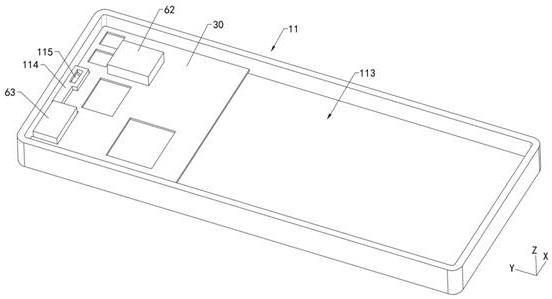
Figure 202211148894

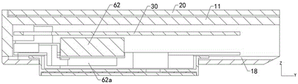
The present application provides an electronic device, which includes a middle frame, a circuit board, a bracket and a first speaker unit, the circuit board includes a mounting surface, and the bracket includes an escape groove; the escape groove extends along the thickness direction of the support The bracket is recessed, the first speaker unit is positioned on the mounting surface and is electrically connected to the circuit board, the circuit board and the bracket are stacked and mounted on the middle frame, and the electronic In the thickness direction of the device, the first speaker unit is accommodated in the escape groove.

Figure 202211148894

Description

电子设备Electronic equipment

技术领域technical field

本申请涉及通讯设备技术领域,尤其涉及一种电子设备。The present application relates to the technical field of communication devices, and in particular, to an electronic device.

背景技术Background technique

随着科学技术的不断发展,手机等电子设备被广泛地应用于人们的日常生活和工作中,已经成为人们必不可少的日常用品。目前的电子设备中,扬声器模组和摄像头模组占据了手机内部大量空间,特别是扬声器模组在厚度上需要一定空间,需要在电路板上开设通槽避让,这样就会占用电路板的空间,影响电路板的器件布局和使用;如果避开电路板,就会增加电子设备整体厚度。With the continuous development of science and technology, electronic devices such as mobile phones are widely used in people's daily life and work, and have become indispensable daily necessities for people. In the current electronic equipment, the speaker module and the camera module occupy a lot of space inside the mobile phone, especially the speaker module needs a certain space in thickness, and a through slot needs to be opened on the circuit board to avoid it, which will occupy the space of the circuit board , affecting the device layout and use of the circuit board; if the circuit board is avoided, the overall thickness of the electronic device will be increased.

发明内容SUMMARY OF THE INVENTION

本申请提供一种电子设备,实现减少扬声器模组在电路板上的占用空间,且避免增加电子设备厚度。The present application provides an electronic device, which can reduce the space occupied by a speaker module on a circuit board and avoid increasing the thickness of the electronic device.

本申请一实施例提供的电子设备,包括中框、电路板、支架和第一扬声器单元,所述电路板包括安装面,所述支架包括避让槽;所述避让槽沿着所述支架厚度方向向所述支架内凹陷,所述第一扬声器单元定位于所述安装面上并与所述电路板电性连接,所述电路板和所述支架层叠且装于所述中框,在所述电子设备厚度方向上,所述第一扬声器单元收容于所述避让槽内。An electronic device provided by an embodiment of the present application includes a middle frame, a circuit board, a bracket, and a first speaker unit, the circuit board includes a mounting surface, and the bracket includes an escape groove; the escape groove is along the thickness direction of the support is recessed into the bracket, the first speaker unit is positioned on the mounting surface and is electrically connected to the circuit board, the circuit board and the bracket are stacked and mounted on the middle frame, and the first speaker unit is positioned on the mounting surface and electrically connected to the circuit board. In the thickness direction of the electronic device, the first speaker unit is accommodated in the escape groove.

本申请实施例电子设备中,将第一扬声器单元安装于电路板的表面,通过在支架上设置避让槽来为第一扬声器单元提供厚度方向的空间,可以避免在电路板上开孔,增加电路板使用面积,而且利用摄像头模组的装饰件空间收容支架,可以避免增加电子设备的厚度空间。In the electronic device of the embodiment of the present application, the first speaker unit is installed on the surface of the circuit board, and the space in the thickness direction is provided for the first speaker unit by setting an escape groove on the bracket, which can avoid opening holes on the circuit board and increase the circuit The use area of the board is reduced, and the space of the decorative part of the camera module is used to accommodate the bracket, which can avoid increasing the thickness space of the electronic device.

一种实施例中,所述电子设备包括第二扬声器单元和出音缝,所述中框包括安装槽,所述电路板包括避让孔,所述避让孔沿所述电路板的厚度方向贯穿所述电路板,所述安装槽沿着所述中框厚度方向贯穿所述中框,所述第二扬声器单元穿设于所述避让孔,且覆盖所述安装槽的开口,所述安装槽形成所述第二扬声器单元的前音腔,所述出音缝连通所述第二扬声器单元的前音腔与所述电子设备的外部。In an embodiment, the electronic device includes a second speaker unit and a sound outlet slot, the middle frame includes a mounting slot, and the circuit board includes an escape hole, and the escape hole penetrates through the thickness direction of the circuit board. In the circuit board, the installation groove penetrates through the middle frame along the thickness direction of the middle frame, the second speaker unit passes through the avoidance hole, and covers the opening of the installation groove, and the installation groove is formed The front sound cavity of the second speaker unit, and the sound outlet slot communicates the front sound cavity of the second speaker unit with the outside of the electronic device.

一种实施例中,所述第二扬声器单元的体积小于所述第一扬声器单元的体积。在外放场景,由于所述第二扬声器单元的体积小,其前音腔体积夜宵,第二扬声器可作为高音单元使用,第一扬声器作为低音单元,提升立体声效果。In one embodiment, the volume of the second speaker unit is smaller than the volume of the first speaker unit. In the external playback scenario, due to the small size of the second speaker unit, the volume of the front sound cavity is night, the second speaker can be used as a tweeter unit, and the first speaker can be used as a woofer unit to improve the stereo effect.

一种实施例中,所述第一扬声器单元为高音单元或全频单元,所述第二扬声器单元为全频单元。本实施例中,具有多个扬声器单元,可以实现多音频效果,而且所述出音缝可作为通话时出音的缝隙,由于人耳无法与出音缝完全贴合密封,因此出音缝的声音会向外扩散,变为漏音,影响通话隐私性,对于此问题,第一扬声器单元通过扬声孔发出与出音缝相位相反的声波,以抵消出音缝的漏音,提升通话隐私性。In one embodiment, the first speaker unit is a tweeter unit or a full-frequency unit, and the second speaker unit is a full-frequency unit. In this embodiment, there are multiple speaker units, which can achieve multi-audio effects, and the sound outlet slot can be used as a gap for sound output during a call. The sound will diffuse outward and become sound leakage, which affects the privacy of the call. For this problem, the first speaker unit emits a sound wave with the opposite phase to the sound outlet through the speaker hole to offset the sound leakage from the sound outlet and improve the privacy of the call. sex.

一种实施例中,所述中框设有端部边框和设于所述端部边框的扬声孔,所述避让槽包括槽底壁,所述槽底壁上凹陷有功能槽,所述第一扬声器单元覆盖所述功能槽,以使所述功能槽形成所述第一扬声器的前音腔,所述扬声孔连通所述第一扬声器单元的前音腔和所述中框的外部。In an embodiment, the middle frame is provided with an end frame and a speaker hole arranged on the end frame, the escape groove includes a groove bottom wall, and a functional groove is recessed on the groove bottom wall, and the The first speaker unit covers the functional slot, so that the functional slot forms a front sound cavity of the first speaker, and the speaker hole communicates with the front sound cavity of the first speaker unit and the outside of the middle frame .

一种实施例中,所述中框包括凸块,所述凸块上设有连通槽,所述连通槽沿着所述中框厚度方向延伸,所述连通槽与所述扬声孔连通,所述支架包括通音孔,所述通音孔连通所述第一扬声器单元的前音腔和所述连通槽。本实施例结构简单便于制作,第一扬声器单元通过所述通音孔、连通槽及扬声孔将声音传递到电子设备外部。In one embodiment, the middle frame includes a protrusion, the protrusion is provided with a communication groove, the communication groove extends along the thickness direction of the middle frame, and the communication groove communicates with the speaker hole, The bracket includes a sound-through hole, and the sound-through hole communicates with the front sound cavity of the first speaker unit and the communication groove. This embodiment has a simple structure and is easy to manufacture, and the first speaker unit transmits the sound to the outside of the electronic device through the sound passage hole, the communication slot and the speaker hole.

一种实施例中,所述支架包括支架本体和凸台,所述支架本体包括第一面和与所述第一面背向设置的第二面,所述凸台位于所述第二面,所述避让槽凹设于所述第一面;In one embodiment, the bracket includes a bracket body and a boss, the bracket body includes a first surface and a second surface disposed away from the first surface, and the boss is located on the second surface, the escape groove is recessed on the first surface;

所述第一面上还凸设有安装凸起,所述通音孔包括依次连通的第一音孔、第二音孔和第三音孔,所述第一音孔沿着所述支架长度方向贯穿所述功能槽的槽侧壁,所述第二音孔设于所述凸台和所述安装凸起内部并沿着所述支架厚度方向延伸,所述第三音孔贯穿所述安装凸起,所述凸块与所述安装凸起对接,所述第三音孔与所述连通槽相对并连通。所述支架利用自身厚度和述安装凸起设置通音孔,有效利用部分结构,可以节省支架面积。A mounting protrusion is also protruded on the first surface, the sound hole includes a first sound hole, a second sound hole and a third sound hole that are connected in sequence, and the first sound hole is along the length of the bracket The direction runs through the groove side wall of the functional groove, the second sound hole is provided inside the boss and the installation protrusion and extends along the thickness direction of the bracket, and the third sound hole penetrates the installation A protrusion, the protrusion is butted with the installation protrusion, and the third sound hole is opposite to and communicated with the communication groove. The bracket uses its own thickness and the mounting protrusion to set the sound-passing hole, effectively utilizes part of the structure, and can save the bracket area.

一种实施例中,所述安装凸起一端沿着所述支架宽度方向延伸有延伸部分,所述延伸部分位于所述安装凸起远离所述避让槽的一端,所述第三音孔由所述安装凸起端部延伸至所述延伸部分,且沿着所述延伸部分长度方向延伸;In one embodiment, an extension portion extends along the width direction of the bracket at one end of the mounting protrusion, the extension portion is located at the end of the mounting protrusion away from the escape groove, and the third sound hole is provided by the bracket. the end of the mounting protrusion extends to the extension part and extends along the length direction of the extension part;

所述连通槽由所述凸块的上表面向所述凸块内凹陷,所述连通槽的开口位于所述凸块的表面,且所述连通槽沿着所述中框宽度方向延伸,所述扬声孔贯穿所述连通槽的一个槽侧壁。The communicating groove is recessed into the convex block from the upper surface of the convex block, the opening of the communicating groove is located on the surface of the convex block, and the communicating groove extends along the width direction of the middle frame, so The speaker hole penetrates one side wall of the communication groove.

一种实施例中,所述凸块包括第一斜面,所述第一斜面背向所述端部边框倾斜设置,所述扬声孔贯穿连通槽的槽底壁并与所述连通槽连通;In one embodiment, the protruding block includes a first inclined surface, and the first inclined surface is inclined away from the end frame, and the speaker hole penetrates the bottom wall of the communication groove and communicates with the communication groove;

所述安装凸起设有延伸部分,所述延伸部分位于所述安装凸起远离所述避让槽的一端,所述延伸部分包括第二斜面,所述第二斜面背向所述安装凸起且相较于所述支架的第一面倾斜,所述第三音孔贯穿所述第二斜面,所述第一斜面和所述第二斜面相对接,所述第三音孔与所述连通槽相对并连通。本实施例中,通过在所述凸块设置第一斜面,来减小凸块的体积,避免电路板上的缺口面积过大,节省电路板的面积。The installation protrusion is provided with an extension portion, the extension portion is located at one end of the installation protrusion away from the escape groove, the extension portion includes a second inclined surface, and the second inclined surface faces away from the installation protrusion and Compared with the inclination of the first surface of the bracket, the third sound hole penetrates the second inclined surface, the first inclined surface and the second inclined surface are butted, and the third sound hole is connected with the communication groove relative and connected. In this embodiment, by setting the first slope on the bump, the volume of the bump is reduced, the area of the notch on the circuit board is prevented from being too large, and the area of the circuit board is saved.

一种实施例中,所述中框包括中板和与所述中板连接的所述端部边框,所述中板包括第一表面和与所述第一表面背向设置的第二表面,所述凸块凸设于所述中板的第一表面并与所述端部边框连接;In one embodiment, the middle frame includes a middle plate and the end frame connected to the middle plate, the middle plate includes a first surface and a second surface disposed away from the first surface, the protruding block is protrudingly arranged on the first surface of the middle plate and is connected with the end frame;

所述连通槽包括第一连通槽和与所述第一连通槽连通的第二连通槽,所述第一连通槽的一个开口位于所述凸块背向所述中板的表面,所述第一连通槽的另一个开口位于所述第二连通槽的一个槽侧壁上;第二连通槽的开口位于所述中板的第二表面。The communication groove includes a first communication groove and a second communication groove communicated with the first communication groove, an opening of the first communication groove is located on the surface of the convex block facing away from the middle plate, the first communication groove is The other opening of a communication groove is located on a groove side wall of the second communication groove; the opening of the second communication groove is located on the second surface of the middle plate.

一种实施例中,所述第一连通槽包括第一槽侧壁,所述第一槽侧壁相较于所述第一连通槽的开口倾斜,部分所述扬声孔贯穿第一槽侧壁;In an embodiment, the first communication slot includes a first slot side wall, the first slot side wall is inclined compared to the opening of the first communication slot, and part of the speaker holes penetrate through the first slot side wall;

所述第二连通槽由所述第二表面向所述中板内凹陷形成,所述第二连通槽包括槽底壁和子槽,所述子槽由所述槽底壁向中板内部凹陷形成,所述子槽包括两个倾斜侧壁和连接两个所述倾斜侧壁的底壁,另一部分所述扬声孔贯穿所述底壁,所述第一连通槽的另一个开口位于一个所述倾斜侧壁上并朝向所述扬声孔。本实施例中,通过在中框的两个面来设置连通槽,即,设置异形连通槽,可以减小凸块的体积,进而减小电路板上为凸块开设的缺口的面积,进而节省电路板的面积。The second communication groove is formed by the depression of the second surface into the middle plate. The second communication groove includes a groove bottom wall and a sub-groove, and the sub-groove is formed by the groove bottom wall being sunken into the middle plate. , the sub-slot includes two inclined side walls and a bottom wall connecting the two inclined side walls, another part of the speaker hole penetrates the bottom wall, and the other opening of the first communication groove is located in a on the inclined side wall and toward the speaker hole. In this embodiment, by providing communication grooves on both sides of the middle frame, that is, providing special-shaped communication grooves, the volume of the bumps can be reduced, thereby reducing the area of the gaps opened for the bumps on the circuit board, thereby saving energy area of the circuit board.

一种实施例中,所述第三音孔的一个开口位于所述第二斜面上,所述第三音孔包括孔壁,所述孔壁的延伸方向与所述第三音孔的延伸方向相交,所述第二音孔的一个开口贯穿所述孔壁与所述第三音孔连通。本实施例中的第三音孔横截面积大于第二音孔的横截面积,第三音孔用于与连通槽连通,实现与扬声孔连通,可以提高发声音效。In an embodiment, an opening of the third sound hole is located on the second inclined surface, the third sound hole includes a hole wall, and the extension direction of the hole wall is the same as the extension direction of the third sound hole. At the intersection, an opening of the second sound hole penetrates the hole wall and communicates with the third sound hole. In this embodiment, the cross-sectional area of the third sound hole is larger than the cross-sectional area of the second sound hole, and the third sound hole is used to communicate with the communication groove, so as to communicate with the speaker hole, which can improve the sound emission effect.

一种实施例中,所述电子设备包括摄像头模组和装饰件,所述装饰件包括收容槽,所述电路板还包括安装避让孔,所述安装避让孔沿着所述电路板厚度方向贯穿所述电路板,所述安装避让孔与所述第一扬声器单元间隔设置;In one embodiment, the electronic device includes a camera module and a decorative part, the decorative part includes a receiving groove, and the circuit board further includes an installation avoidance hole, and the installation avoidance hole penetrates along the thickness direction of the circuit board. In the circuit board, the installation avoidance hole is spaced apart from the first speaker unit;

所述摄像头模组穿设所述安装避让孔,所述装饰件装于中框上,所述摄像头模组和所述支架的凸块收容于所述收容槽内。本实施例中,利用收容摄像头模组的装饰件空间来容纳收容第一扬声器单元的支架,避免增加电子设备的厚度。The camera module passes through the installation avoidance hole, the decorative piece is mounted on the middle frame, and the camera module and the bump of the bracket are accommodated in the accommodating groove. In this embodiment, the space of the decorative element for accommodating the camera module is used to accommodate the bracket for accommodating the first speaker unit, so as to avoid increasing the thickness of the electronic device.

一种实施例中,所述电子设备包括屏幕,所述中框包括中板、与中框连接的端部边框和出音槽,所述中板包括第一表面和与所述第一表面背向设置的第二表面,所述出音槽凹设于所述第二表面,所述出音槽包括凹设于所述端部边框的内侧面的缝隙和与所述安装槽连通的连接区,所述屏幕装于所述第二表面并覆盖所述连接区,所述屏幕与所述缝隙形成所述出音缝。出音缝设于显示屏的一侧便于使用者听取声音。In an embodiment, the electronic device includes a screen, the middle frame includes a middle plate, an end frame connected to the middle frame, and a sound outlet, the middle plate includes a first surface and a back surface from the first surface. The sound outlet groove is recessed on the second surface, and the sound outlet groove includes a slot recessed on the inner side of the end frame and a connection area that communicates with the installation groove. , the screen is mounted on the second surface and covers the connection area, and the screen and the gap form the sound outlet gap. The sound outlet is arranged on one side of the display screen to facilitate the user to listen to the sound.

附图说明Description of drawings

为了更清楚地说明本申请实施例的技术方案,下面将对本申请实施例所需要使用的附图进行说明。In order to illustrate the technical solutions of the embodiments of the present application more clearly, the accompanying drawings required to be used in the embodiments of the present application will be described below.

图1是本申请实施例提供的电子设备的结构示意图;1 is a schematic structural diagram of an electronic device provided by an embodiment of the present application;

图2是图1所示电子设备在另一个角度下的结构示意图;Fig. 2 is the structural representation of the electronic device shown in Fig. 1 under another angle;

图3是图2所示电子设备的一个角度分解结构示意图;Fig. 3 is an angular exploded structural schematic diagram of the electronic device shown in Fig. 2;

图4是图1所示电子设备的一个角度分解结构示意图;Fig. 4 is a schematic diagram of an angular exploded structure of the electronic device shown in Fig. 1;

图5是图3所示电子设备的中框的结构示意图;Fig. 5 is the structural representation of the middle frame of the electronic device shown in Fig. 3;

图6是图4所示中框在另一个角度下的结构示意图;Fig. 6 is the structural representation of the middle frame shown in Fig. 4 under another angle;

图7是图5所示的中框的一个角度的截面示意图;FIG. 7 is a schematic cross-sectional view of the middle frame shown in FIG. 5 at an angle;

图8是图6所示的中的一个角度的截面示意图;Figure 8 is a schematic cross-sectional view at an angle shown in Figure 6;

图9是图3所示电子设备中电路板的结构示意图;Fig. 9 is the structural representation of the circuit board in the electronic device shown in Fig. 3;

图10 是图3所示电子设备部分结构组装示意图;Fig. 10 is a schematic view of the partial structure assembly of the electronic equipment shown in Fig. 3;

图11是图3所示电子设备中支架的结构示意图;Fig. 11 is the structural representation of the bracket in the electronic device shown in Fig. 3;

图12是图11所示支架在另一个角度下的结构示意图;Figure 12 is a schematic structural diagram of the bracket shown in Figure 11 at another angle;

图13是图12所示支架的平面结构示意图;Figure 13 is a schematic plan view of the bracket shown in Figure 12;

图14是图2所示的电子设备的一个角度的部分结构剖视图;14 is a partial structural cross-sectional view of the electronic device shown in FIG. 2 from an angle;

图15是图2所示的电子设备的另一个角度的部分结构剖视图;15 is a partial structural cross-sectional view of the electronic device shown in FIG. 2 from another angle;

图16是图1所示电子设备一角度的剖面结构示意图;FIG. 16 is a schematic cross-sectional structure diagram of the electronic device shown in FIG. 1 at an angle;

图17是图1所示电子设备另一角度的剖面结构示意图;17 is a schematic cross-sectional structure diagram of the electronic device shown in FIG. 1 from another angle;

图18是本申请第二实施例提供的电子设备的分解结构示意图;18 is a schematic diagram of an exploded structure of an electronic device provided by the second embodiment of the present application;

图19是图18所示电子设备的支架的另一个角度下的结构示意图;FIG. 19 is a schematic structural diagram of the bracket of the electronic device shown in FIG. 18 from another angle;

图20是本申请第二实施例提供的电子设备部分结构组装示意图;FIG. 20 is a schematic assembly diagram of a partial structure of an electronic device provided by the second embodiment of the present application;

图21是图17所示的电子设备的组装后的截面示意图;21 is a schematic cross-sectional view of the electronic device shown in FIG. 17 after assembly;

图22是本申请第三实施例提供的电子设备的分解结构示意图;22 is a schematic diagram of an exploded structure of an electronic device provided by a third embodiment of the present application;

图23是图22所示电子设备的支架的一个角度下的结构示意图;Figure 23 is a schematic structural diagram of the bracket of the electronic device shown in Figure 22 from an angle;

图24是图22所示电子设备的支架的另一个角度下的结构示意图;FIG. 24 is a schematic structural diagram of the bracket of the electronic device shown in FIG. 22 from another angle;

图25是本申请第三实施例提供的电子设备部分结构组装示意图;FIG. 25 is a schematic assembly diagram of a partial structure of an electronic device provided by the third embodiment of the present application;

图26是图25所示的电子设备的组装后的一角度的截面示意图。FIG. 26 is a schematic cross-sectional view at an angle of the electronic device shown in FIG. 25 after being assembled.

具体实施方式Detailed ways

下面将结合本申请实施例中的附图,对本申请实施例中的技术方案进行清楚、完整地描述。The technical solutions in the embodiments of the present application will be clearly and completely described below with reference to the accompanying drawings in the embodiments of the present application.

请参阅图1至图2,图1是本申请实施例提供的电子设备1000的结构示意图,图2是图1所示电子设备1000在另一个角度下的结构示意图。Please refer to FIGS. 1 to 2 . FIG. 1 is a schematic structural diagram of an electronic device 1000 provided by an embodiment of the present application, and FIG. 2 is a structural schematic diagram of the electronic device 1000 shown in FIG. 1 from another angle.

电子设备1000可以是手机、平板电脑、笔记本电脑、车机、智能手表、智能手环、POS机(point of sales terminal,销售点终端)等电子产品。本申请实施例以电子设备1000是手机为例进行说明。其中,为了便于描述,定义电子设备1000的宽度方向为X轴方向,电子设备1000的长度方向为Y轴方向,电子设备1000的厚度方向为Z轴方向,X轴方向、Y轴方向和Z轴方向两两相互垂直。需要说明的是,本申请中涉及的“顶”、“底”、“上”、“下”、“左”和“右”等方位用词,是参考附图1所示的方位进行的描述,以朝向Y轴正方向为“顶”,以朝向Y轴负方向为“底”,以朝向Z轴正方向为“上”,以朝向Z轴负方向为“下”,以朝向X轴正方向为“右”,以朝向X轴负方向为“左”,其并不是指示或暗指所指的装置或元件必须具有特定的方位、以特定的方位构造和操作,因此不能理解为对本申请的限制。The electronic device 1000 may be an electronic product such as a mobile phone, a tablet computer, a notebook computer, a car device, a smart watch, a smart bracelet, a POS machine (point of sales terminal, point of sale terminal). The embodiments of the present application are described by taking the electronic device 1000 as a mobile phone as an example. For convenience of description, the width direction of the electronic device 1000 is defined as the X-axis direction, the length direction of the electronic device 1000 is defined as the Y-axis direction, the thickness direction of the electronic device 1000 is defined as the Z-axis direction, the X-axis direction, the Y-axis direction and the Z-axis direction The directions are perpendicular to each other. It should be noted that the orientation terms such as "top", "bottom", "upper", "down", "left" and "right" involved in this application are described with reference to the orientation shown in FIG. 1 . , take the positive direction of the Y-axis as "top", take the negative direction of the Y-axis as the "bottom", take the positive direction of the Z-axis as "up", take the negative direction of the Z-axis as "down", and take the positive direction of the X-axis as "bottom" The direction is "right", and the negative direction toward the X-axis is "left", which does not indicate or imply that the device or element referred to must have a specific orientation, be constructed and operated in a specific orientation, and therefore should not be construed as affecting the present application. limits.

请参阅图3和图4,图3是图2所示电子设备1000的一个角度分解结构示意图,图4是图1所示电子设备1000的一个角度分解结构示意图。电子设备1000包括壳体10、屏幕20、电路板30、支架40、处理器(图未示)、摄像模组、扬声器模组(图未示)、电源模组(图未示)和装饰件70。屏幕20安装于壳体10的一侧。电路板30、支架40、处理器、摄像模组、扬声器模组和电源模组均安装于壳体10的内侧。处理器可安装于电路板30,且与电路板30电连接。其中,处理器可为电子设备1000的CPU(central processing unit,中央处理器)。装饰件70安装于壳体10的另一侧,且覆盖支架40。Please refer to FIG. 3 and FIG. 4 , FIG. 3 is a schematic view of an angular exploded structure of the electronic device 1000 shown in FIG. 2 , and FIG. 4 is a schematic view of an angular exploded structure of the electronic device 1000 shown in FIG. 1 . The electronic device 1000 includes a casing 10 , a screen 20 , a circuit board 30 , a bracket 40 , a processor (not shown), a camera module, a speaker module (not shown), a power module (not shown), and decorative parts 70. The screen 20 is installed on one side of the casing 10 . The circuit board 30 , the bracket 40 , the processor, the camera module, the speaker module and the power module are all mounted on the inner side of the casing 10 . The processor can be mounted on the circuit board 30 and is electrically connected to the circuit board 30 . The processor may be a CPU (central processing unit, central processing unit) of the electronic device 1000 . The decorative element 70 is installed on the other side of the casing 10 and covers the bracket 40 .

扬声器模组位于电子设备1000的顶部,且用作电子设备1000的顶部扬声器模组。扬声器模组包括第二扬声器单元63和第一扬声器单元62。第二扬声器单元63可为高频单元,且可用作电子设备1000的听筒。第二扬声器单元63可通过电路板30接收处理器发送的音频信号,并根据音频信号振动发声,声音扩散至外界环境中,实现电子设备1000的听筒发声。第一扬声器单元62与电路板30电连接,以实现与处理器之间的电连接。其中,第一扬声器单元62可为全频单元,且可用作电子设备1000的喇叭,也可以是低频单元,提升立体声效果。第一扬声器单元62可通过电路板30接收处理器发送的音频信号,并根据音频信号振动发声,声音扩散至外界环境中,实现电子设备1000的喇叭发声。在其他实施例中,第二扬声器单元63和第一扬声器单元62可均为全频单元,扬声器模组可实现三声道发声,有助于提升扬声器模组的发声质量。电子设备1000还设有扬声孔80和出音缝90,本实施例的扬声孔80和出音缝90位于电子设备的顶部。在其他实施例中,第二扬声器单元63可以省略,省略后,第一扬声器单元62出音方式可以通过扬声孔80和出音缝90,也可以是扬声孔80,或者是出音缝90。The speaker module is located on the top of the electronic device 1000 and is used as the top speaker module of the electronic device 1000 . The speaker module includes a second speaker unit 63 and a first speaker unit 62 . The second speaker unit 63 may be a high frequency unit, and may be used as an earpiece of the electronic device 1000 . The second speaker unit 63 can receive the audio signal sent by the processor through the circuit board 30, and vibrate and emit sound according to the audio signal. The first speaker unit 62 is electrically connected with the circuit board 30 to realize electrical connection with the processor. The first speaker unit 62 may be a full-frequency unit, and may be used as a speaker of the electronic device 1000, or may be a low-frequency unit to enhance the stereo effect. The first speaker unit 62 can receive the audio signal sent by the processor through the circuit board 30, and vibrate and emit sound according to the audio signal. In other embodiments, the second speaker unit 63 and the first speaker unit 62 can both be full-frequency units, and the speaker module can realize three-channel sound, which helps to improve the sound quality of the speaker module. The electronic device 1000 is further provided with a speaker hole 80 and a sound outlet slot 90. The speaker hole 80 and the sound outlet slot 90 in this embodiment are located at the top of the electronic device. In other embodiments, the second speaker unit 63 may be omitted. After the omission, the sound output of the first speaker unit 62 may be through the speaker hole 80 and the sound outlet slot 90, or the speaker hole 80 or the sound outlet slot. 90.

本实施例中,壳体10包括中框11和后盖18,后盖18安装于中框11的一侧。后盖18可为电子设备1000的电池盖。后盖18设有安装孔181,安装孔181位于后盖18的顶部并贯穿后盖18。即,安装孔181沿后盖18的厚度方向(图示Z轴方向)贯穿后盖18。安装孔181为方形孔。在其他实施例中,安装孔181也可以为圆形孔或其他形状的孔。扬声孔80位于中框11的一端。本实施例中,屏幕20可以是LCD(liquid crystal display,液晶显示屏)或OLED(organic light-emitting diode,有机发光二极管显示屏)等显示屏,且用于显示图像或文字等信息。屏幕20装于中框11的另一侧,即屏幕20安装于中框11背离后盖18的一侧。出音缝90位于屏幕20的顶部。In this embodiment, the housing 10 includes a middle frame 11 and a rear cover 18 , and the rear cover 18 is installed on one side of the middle frame 11 . The back cover 18 may be a battery cover of the electronic device 1000 . The rear cover 18 is provided with an installation hole 181 , and the installation hole 181 is located at the top of the rear cover 18 and penetrates through the rear cover 18 . That is, the mounting hole 181 penetrates the rear cover 18 in the thickness direction (the Z-axis direction in the figure) of the rear cover 18 . The mounting hole 181 is a square hole. In other embodiments, the mounting holes 181 may also be circular holes or holes of other shapes. The speaker hole 80 is located at one end of the middle frame 11 . In this embodiment, the screen 20 may be a display screen such as an LCD (liquid crystal display, liquid crystal display) or an OLED (organic light-emitting diode, organic light-emitting diode display), and is used to display information such as images or text. The screen 20 is mounted on the other side of the middle frame 11 , that is, the screen 20 is mounted on the side of the middle frame 11 away from the back cover 18 . The sound exit slot 90 is located at the top of the screen 20 .

装饰件70呈矩形罩状。装饰件70设有收容槽71和安装边72,安装边72为装饰件70的外周缘。装饰件70装于后盖18的安装孔181上,安装边72与安装孔181周缘固定卡持,装饰件70凸出后盖18的外表面。收容槽71的开口位于装饰件70的一侧。收容槽71自装饰件70的上表面向下表面(图未标)的方向(图示Z轴负方向)凹陷。其中,收容槽71的形状与支架40的形状相适配。装饰件70还可设有摄像孔(图未标),摄像孔的开口位于收容槽71的槽底壁。摄像孔自收容槽71的槽底壁向装饰件70的下表面的方向凹陷,且贯穿装饰件70的下表面。其中,外界的光线可经摄像孔进入装饰件70的收容槽71。The decorative piece 70 is in the shape of a rectangular cover. The decoration piece 70 is provided with a receiving groove 71 and a mounting edge 72 , and the mounting edge 72 is the outer periphery of the decoration piece 70 . The decorative piece 70 is mounted on the mounting hole 181 of the rear cover 18 , the mounting edge 72 is fixedly clamped with the periphery of the mounting hole 181 , and the decorative piece 70 protrudes from the outer surface of the rear cover 18 . The opening of the receiving groove 71 is located on one side of the decorative element 70 . The accommodating groove 71 is recessed from the upper surface of the decorative member 70 to the lower surface (not shown) in the direction (the negative Z-axis direction in the figure). The shape of the receiving groove 71 is adapted to the shape of the bracket 40 . The decorative element 70 may also be provided with a camera hole (not shown), and the opening of the camera hole is located on the bottom wall of the receiving groove 71 . The imaging hole is recessed from the bottom wall of the receiving groove 71 toward the lower surface of the decorative element 70 and penetrates through the lower surface of the decorative element 70 . The external light can enter the receiving groove 71 of the decorative element 70 through the camera hole.

请参阅图4、图5和图6,图5是图3所示电子设备1000的中框11的结构示意图,图6是图4所示中框11在另一个角度下的结构示意图。4 , 5 and 6 , FIG. 5 is a schematic structural diagram of the middle frame 11 of the electronic device 1000 shown in FIG. 3 , and FIG. 6 is a structural schematic diagram of the middle frame 11 shown in FIG. 4 from another angle.

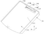
中框11包括中板111和两个端部边框112和两个侧部边框(图未标),中板111包括第一表面1110和与第一表面1110背向设置的第二表面1111。两个端部边框112和两个侧部边框首位连接且均与中板111侧部连接,两个端部边框112和两个侧部边框围绕中板111周侧与中板111形成容纳槽113。第一表面1110为容纳槽113的槽底面。本实施例的中板111为矩形板,位于中板111端边的两个端部边框112可以看成是电子设备的顶部和底部外壳,通常用于设置扬声孔和连接器插口等。位于中板相对两侧的侧部边框可以看成是电子设备的两个侧部外壳,可以设置音量键、开关机键等,也是使用者手握持的部分。本实施例中,位于顶部的端部边框112上设有扬声孔80,用于与扬声器模组配合。The middle frame 11 includes a middle plate 111 , two end frames 112 and two side frames (not shown). The middle frame 111 includes a first surface 1110 and a second surface 1111 disposed away from the first surface 1110 . The two end frames 112 and the two side frames are connected at the first place and are both connected to the sides of the middle plate 111 . The two end frames 112 and the two side frames surround the circumference of the middle plate 111 and form a receiving groove 113 with the middle plate 111 . . The first surface 1110 is the groove bottom surface of the accommodating groove 113 . The middle plate 111 in this embodiment is a rectangular plate, and the two end frames 112 located at the ends of the middle plate 111 can be regarded as the top and bottom shells of the electronic device, and are usually used for setting speaker holes and connector sockets. The side frames located on the opposite sides of the middle plate can be regarded as two side shells of the electronic device, which can be provided with volume keys, power on/off keys, etc., which are also the parts held by the user's hand. In this embodiment, the end frame 112 at the top is provided with a speaker hole 80 for matching with the speaker module.

本实施例中,中框11还包括凸块114,凸块114凸设于容纳槽113的槽底面(第一表面1110)且向容纳槽113的开口方向(图示Z轴负方向)延伸。具体的,凸块114呈矩形,凸块114位于容纳槽113的顶部,凸块114连接端部边框112内侧面。其中,凸块114的高度小于容纳槽113的深度。示例性的,凸块114呈方形。在其它实施例中,凸块114也可以呈圆形或其他形状。In this embodiment, the middle frame 11 further includes a protrusion 114 . The protrusion 114 is protruded from the groove bottom surface (first surface 1110 ) of the receiving groove 113 and extends toward the opening direction of the receiving groove 113 (the negative Z-axis direction shown in the figure). Specifically, the protruding block 114 is rectangular, the protruding block 114 is located at the top of the receiving groove 113 , and the protruding block 114 is connected to the inner side surface of the end frame 112 . Wherein, the height of the bump 114 is smaller than the depth of the accommodating groove 113 . Illustratively, the bumps 114 are square. In other embodiments, the bumps 114 may also be circular or other shapes.

请一并参阅图5和图6,中框11还设有连通槽115、安装槽117和出音槽118。出音槽118和安装槽117均位于中框11的顶部。安装槽117沿中框11的厚度方向贯穿中板111的第一表面和第二表面。出音槽118包括缝隙1181和连接区1182,缝隙1181沿着端部边框112(X轴方向)延伸,具体是凹设于端部边框112的内侧面,并贯穿端部边框112的上表面,即与第一表面1110朝向相同的面。出音槽118部分凹设于中板111的第二表面1111(自中板111的第二表面向第一表面的方向(图示Z轴负方向)凹陷),连接区1182位于安装槽117一侧并与安装槽117连通。Please refer to FIG. 5 and FIG. 6 together, the middle frame 11 is further provided with a communication slot 115 , an installation slot 117 and a sound outlet slot 118 . Both the sound outlet slot 118 and the installation slot 117 are located at the top of the middle frame 11 . The installation groove 117 penetrates through the first surface and the second surface of the middle plate 111 along the thickness direction of the middle frame 11 . The sound outlet 118 includes a slit 1181 and a connecting area 1182. The slit 1181 extends along the end frame 112 (X-axis direction), specifically, is recessed on the inner side of the end frame 112 and penetrates through the upper surface of the end frame 112. That is, it faces the same plane as the first surface 1110 . The sound outlet groove 118 is partially recessed on the second surface 1111 of the middle plate 111 (recessed in the direction from the second surface of the middle plate 111 to the first surface (the negative direction of the Z axis in the figure)), and the connection area 1182 is located at the end of the installation groove 117. side and communicate with the installation groove 117 .

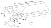
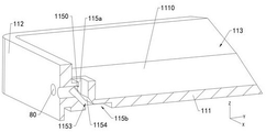
请一并参阅图6、图7和图8,图7是图5所示的中框11的一个角度的截面示意图;图8是图6所示的中框11的一个角度的截面示意图。连通槽115贯穿凸块114和中板111的第二表面1111并与扬声孔80连通。连通槽115的一个开口位于凸块114的上表面(图未标),另一个开口位于第二表面1111上。具体的,连通槽115包括第一连通槽115a和第二连通槽115b,第一连通槽115a的开口位于凸块114的上表面并与容纳槽113连通。第一连通槽115a包括第一槽侧壁1150,第一槽侧壁1150与端部边框112连接,第一槽侧壁1150相较于第一连通槽115a开口倾斜,部分扬声孔80贯穿第一槽侧壁1150与第一连通槽115a连通。Please refer to FIGS. 6 , 7 and 8 together. FIG. 7 is a schematic cross-sectional view of the middle frame 11 shown in FIG. 5 at an angle; FIG. 8 is a cross-sectional schematic view of the middle frame 11 shown in FIG. 6 at an angle. The communication groove 115 penetrates through the bump 114 and the second surface 1111 of the middle plate 111 and communicates with the speaker hole 80 . One opening of the communication groove 115 is located on the upper surface (not shown) of the bump 114 , and the other opening is located on the second surface 1111 . Specifically, the communication groove 115 includes a first communication groove 115 a and a second communication groove 115 b . The opening of the first communication groove 115 a is located on the upper surface of the protrusion 114 and communicates with the accommodating groove 113 . The first communication slot 115a includes a first slot side wall 1150, the first slot side wall 1150 is connected to the end frame 112, the first slot side wall 1150 is inclined relative to the opening of the first communication slot 115a, and part of the speaker hole 80 penetrates through the first slot 115a. A groove side wall 1150 communicates with the first communication groove 115a.

第二连通槽115b的开口位于第二表面1111上,在X轴方向上第二连通槽115b与安装槽117间隔排列,且在Y轴方向上与出音槽118间隔设置。第二连通槽115b包括槽底壁1152和子槽1153,第二连通槽115b由第二表面1111向中板111内凹陷形成,第二连通槽115b的开口背向容纳槽113,位于中板的第二表面。槽底壁1152与第二表面1111平行。子槽1153由槽底壁1152向中板111内部凹陷形成(具体是向凸块114内凹陷),子槽1153与部分所述扬声孔80连通。实际上,第一连通槽115a在第二连通槽115b的投影范围内。The opening of the second communication groove 115b is located on the second surface 1111 , the second communication groove 115b is spaced from the mounting groove 117 in the X-axis direction, and is spaced from the sound outlet groove 118 in the Y-axis direction. The second communication groove 115b includes a groove bottom wall 1152 and a sub-groove 1153. The second communication groove 115b is formed by the second surface 1111 recessed into the middle plate 111. The opening of the second communication groove 115b faces away from the accommodating groove 113 and is located on the second surface of the middle plate 111. Second surface. The groove bottom wall 1152 is parallel to the second surface 1111 . The sub-slot 1153 is formed by the recess of the bottom wall 1152 of the slot into the middle plate 111 (specifically, the recess is recessed into the protrusion 114 ), and the sub-slot 1153 communicates with part of the speaker holes 80 . Actually, the first communication groove 115a is within the projection range of the second communication groove 115b.

具体的,子槽1153包括两个倾斜侧壁1154和与倾斜侧壁1154连接的底壁1155,扬声孔80贯穿底壁1155与子槽1153连通。第一连通槽115a贯穿一个所述倾斜侧壁1154与子槽1153连通,即第一连通槽115a的另一个开口位于倾斜侧壁1154上并朝向底壁1155。其中,子槽1153是倾斜的槽,其由中板111向凸块114内凹设,底壁1155可以是端部边框112的一部分,也可以是凸块的一部分。可以理解为,第一连通槽115a贯穿第二连通槽115b的部分槽侧壁。第二连通槽115b的面积较大,便于第一连通槽115a的加工,也可以减小第一连通槽115a的尺寸,进而减小凸块的尺寸,可以减小电路板30上的缺口的尺寸,进而增加了电路板的实际使用面积。Specifically, the sub-slot 1153 includes two inclined side walls 1154 and a bottom wall 1155 connected with the inclined side walls 1154 , and the speaker hole 80 penetrates the bottom wall 1155 and communicates with the sub-slot 1153 . The first communication groove 115a passes through one of the inclined side walls 1154 and communicates with the sub-groove 1153 , that is, the other opening of the first communication groove 115 a is located on the inclined side wall 1154 and faces the bottom wall 1155 . The sub-slot 1153 is an inclined slot, which is recessed from the middle plate 111 to the convex block 114, and the bottom wall 1155 can be a part of the end frame 112 or a part of the convex block. It can be understood that the first communication groove 115a penetrates part of the groove side wall of the second communication groove 115b. The area of the second communication groove 115b is larger, which is convenient for the processing of the first communication groove 115a, and the size of the first communication groove 115a can also be reduced, thereby reducing the size of the bump and the size of the notch on the circuit board 30. , thereby increasing the actual usable area of the circuit board.

请参阅图9和图10,图9是图3所示电子设备1000中电路板30的结构示意图,其中包括了扬声器模组。图10是图3所示电子设备1000部分结构组装示意图。Please refer to FIGS. 9 and 10 . FIG. 9 is a schematic structural diagram of the circuit board 30 in the electronic device 1000 shown in FIG. 3 , which includes a speaker module. FIG. 10 is a schematic assembly diagram of a part of the structure of the electronic device 1000 shown in FIG. 3 .

电路板30可为电子设备1000的主板(main board)。电路板30包括安装面31,安装面31上设有第一安装区311和与第一安装区311相邻的第二安装区312。电路板30还设有避让孔32、多个安装避让孔33及缺口34。避让孔32、多个安装避让孔33(两个或者两个以上)及缺口34沿着电路板30厚度方向(Z轴方向)贯穿电路板30,即贯穿安装面31及与安装面31背向的表面。The circuit board 30 may be a main board of the electronic device 1000 . The circuit board 30 includes a mounting surface 31 . The mounting surface 31 is provided with a first mounting area 311 and a second mounting area 312 adjacent to the first mounting area 311 . The circuit board 30 is further provided with avoidance holes 32 , a plurality of installation avoidance holes 33 and notches 34 . The avoidance hole 32 , the plurality of installation avoidance holes 33 (two or more) and the notch 34 penetrate through the circuit board 30 along the thickness direction (Z-axis direction) of the circuit board 30 , that is, pass through the mounting surface 31 and face away from the mounting surface 31 . s surface.

其中,避让孔32、安装避让孔33及缺口34间隔设置;避让孔32和缺口34位于电路板30的顶部,且贯穿电路板30的顶端面(图未标)。缺口34位于避让孔32一侧。多个安装避让孔33位于电路板30的第一安装区311,缺口34和避让孔32位于第一安装区311上方。需要说明的是,电路板30中位于避让孔32和安装避让孔33之间的部分,一般用于走射频信号线和控制线等线路,避让孔32和安装避让孔33之间的距离可便于排布射频信号线和控制线等线路,保证电路板30的使用可靠性。The avoidance hole 32 , the installation avoidance hole 33 and the notch 34 are arranged at intervals; the avoidance hole 32 and the notch 34 are located on the top of the circuit board 30 and penetrate through the top surface of the circuit board 30 (not shown). The notch 34 is located on the side of the escape hole 32 . The plurality of installation avoidance holes 33 are located in the first installation area 311 of the circuit board 30 , and the notches 34 and the avoidance holes 32 are located above the first installation area 311 . It should be noted that the part of the circuit board 30 located between the avoidance hole 32 and the installation avoidance hole 33 is generally used to route lines such as radio frequency signal lines and control lines, and the distance between the avoidance hole 32 and the installation avoidance hole 33 can be convenient. Lines such as radio frequency signal lines and control lines are arranged to ensure the reliability of the use of the circuit board 30 .

请参阅图10,电路板30、摄像模组(图未示)和扬声器模组均安装于中框11的容纳槽113。具体的,电路板30安装于容纳槽113的槽底壁(图未标)。电路板30的缺口34避让中框11的凸块114。摄像模组安装于容纳槽113的槽底壁,且穿设于电路板30的多个安装避让孔33。摄像模组与电路板30电连接,以实现与处理器之间的电连接。摄像模组可通过电路板30接收处理器发送的信息采集信号,并采集电子设备1000外部的光线,以形成对应的图像数据。Please refer to FIG. 10 , the circuit board 30 , the camera module (not shown) and the speaker module are all installed in the accommodating slot 113 of the middle frame 11 . Specifically, the circuit board 30 is mounted on the bottom wall of the receiving groove 113 (not marked in the figure). The notches 34 of the circuit board 30 avoid the bumps 114 of the middle frame 11 . The camera module is installed on the bottom wall of the accommodating groove 113 and penetrates through the plurality of installation avoidance holes 33 of the circuit board 30 . The camera module is electrically connected to the circuit board 30 to realize electrical connection with the processor. The camera module can receive the information collection signal sent by the processor through the circuit board 30, and collect the light outside the electronic device 1000 to form corresponding image data.

扬声器模组的第二扬声器单元63位于电子设备1000的顶部,第二扬声器单元63安装于安装槽117。具体的,第二扬声器单元63穿设于电路板30的安装避让孔33,且与电路板30电连接,以实现与处理器之间的电连接。其中,第二扬声器单元63可为高频单元,且可用作电子设备1000的听筒。第二扬声器单元63可通过电路板30接收处理器发送的音频信号,并根据音频信号振动发声,声音扩散至外界环境中,实现电子设备1000的听筒发声。The second speaker unit 63 of the speaker module is located on the top of the electronic device 1000 , and the second speaker unit 63 is installed in the installation slot 117 . Specifically, the second speaker unit 63 passes through the installation avoidance hole 33 of the circuit board 30 and is electrically connected to the circuit board 30 to realize electrical connection with the processor. Wherein, the second speaker unit 63 can be a high frequency unit, and can be used as an earpiece of the electronic device 1000 . The second speaker unit 63 can receive the audio signal sent by the processor through the circuit board 30, and vibrate and emit sound according to the audio signal.

第一扬声器单元62安装于电路板30的第二安装区312,也就是安装面31上,且与电路板30电连接,以实现与处理器之间的电连接。沿X轴方向上,第一扬声器单元62与摄像模组间隔设置。本实施例中的第一扬声器单元62直接设置于电路板30的安装面31上,不需要在电路板30上设置贯穿电路板的避让孔,可以节省电路板30的空间。其中,第一扬声器单元62可为全频单元,且可用作电子设备1000的喇叭;当然还可以作为低音单元使用。第一扬声器单元62可通过电路板30接收处理器发送的音频信号,并根据音频信号振动发声,声音扩散至外界环境中,实现电子设备1000的喇叭发声。此时,第一扬声器单元62可与第二扬声器单元63协同发声,可降低扬声器模组的功耗,有助于延长电子设备1000的续航时间。The first speaker unit 62 is mounted on the second mounting area 312 of the circuit board 30 , that is, on the mounting surface 31 , and is electrically connected to the circuit board 30 to achieve electrical connection with the processor. Along the X-axis direction, the first speaker unit 62 is spaced apart from the camera module. In this embodiment, the first speaker unit 62 is directly disposed on the mounting surface 31 of the circuit board 30 , and there is no need to provide an escape hole penetrating the circuit board on the circuit board 30 , which can save the space of the circuit board 30 . The first speaker unit 62 can be a full-frequency unit, and can be used as a speaker of the electronic device 1000; of course, it can also be used as a bass unit. The first speaker unit 62 can receive the audio signal sent by the processor through the circuit board 30, and vibrate and emit sound according to the audio signal. At this time, the first speaker unit 62 and the second speaker unit 63 can cooperate to produce sound, which can reduce the power consumption of the speaker module and help prolong the battery life of the electronic device 1000 .

此外,电子设备1000还可包括另一扬声器模组(图未示),另一扬声器模组位于电子设备1000的底部,且用作电子设备1000的底部扬声器模组。此时,电子设备1000可同时采用顶部扬声器模组和底部扬声器模组发声,以实现电子设备1000的“双喇叭”发声模式,有助于提升电子设备1000的发声质量。In addition, the electronic device 1000 may further include another speaker module (not shown), and the other speaker module is located at the bottom of the electronic device 1000 and used as a bottom speaker module of the electronic device 1000 . At this time, the electronic device 1000 can use the top speaker module and the bottom speaker module to produce sound at the same time, so as to realize the "dual speaker" sound mode of the electronic device 1000 , which helps to improve the sound quality of the electronic device 1000 .

请参阅图11和图12,图11是图3所示电子设备1000中支架40的结构示意图,图12是图11所示支架40在另一个角度下的结构示意图,图13是图12所示支架40的平面结构示意图。Please refer to FIGS. 11 and 12 , FIG. 11 is a schematic structural diagram of the bracket 40 in the electronic device 1000 shown in FIG. 3 , FIG. 12 is a schematic structural diagram of the bracket 40 shown in FIG. 11 from another angle, and FIG. 13 is the schematic diagram of FIG. 12 . A schematic diagram of the plane structure of the bracket 40 .

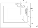
本实施例中,支架40包括支架本体41、凸台42、装配槽43、避让槽45以及安装凸起46以及通音孔47,凸台42和安装凸起46固定连接于支架本体41。支架本体41与中框11的容纳槽113(如图4所示)的形状相适配。支架本体41包括第一面411和与第一面411背向设置的第二面412。In this embodiment, the bracket 40 includes a bracket body 41 , a boss 42 , an assembly slot 43 , an escape slot 45 , an installation protrusion 46 and a sound hole 47 , and the boss 42 and the installation protrusion 46 are fixedly connected to the bracket body 41 . The bracket body 41 is adapted to the shape of the accommodating groove 113 (as shown in FIG. 4 ) of the middle frame 11 . The bracket body 41 includes a first surface 411 and a second surface 412 disposed away from the first surface 411 .

凸台42固定连接于支架本体41的第二面412。凸台42自支架本体41的第二面412向远离第二面412的方向(图示Z轴正方向)凸出。装配槽43贯穿第一面411和第二面412上的凸台42,即装配槽43为通槽,其两个开口分别位于第一面411和凸台42背向第二面412的一侧。装配槽43的形状与摄像模组的形状相适配。The boss 42 is fixedly connected to the second surface 412 of the bracket body 41 . The boss 42 protrudes from the second surface 412 of the bracket body 41 in a direction away from the second surface 412 (the positive direction of the Z axis in the figure). The mounting groove 43 passes through the bosses 42 on the first surface 411 and the second surface 412 , that is, the mounting groove 43 is a through groove, and its two openings are located on the side of the first surface 411 and the boss 42 facing away from the second surface 412 respectively. . The shape of the assembling groove 43 is adapted to the shape of the camera module.

避让槽45凹设于第一面411上,沿Z轴方向,避让槽45由第一面411向第二面412方向凹陷;沿着X轴方向,避让槽45与装配槽43间隔设置。避让槽45的形状与第一扬声器单元62形状相适配,用于容纳第一扬声器单元62。避让槽45平行于第一面411的槽底壁450上凹设有功能槽451,第一扬声器单元覆盖功能槽451,功能槽451作为第一扬声器单元62的前音腔。The avoidance groove 45 is recessed on the first surface 411 , along the Z-axis direction, the avoidance groove 45 is recessed from the first surface 411 to the second surface 412 ; along the X-axis direction, the avoidance groove 45 is spaced from the assembly groove 43 . The shape of the escape groove 45 is adapted to the shape of the first speaker unit 62 for accommodating the first speaker unit 62 . A functional groove 451 is recessed on the groove bottom wall 450 of the escape groove 45 parallel to the first surface 411 .

安装凸起46凸设于支架本体41的第一面411上,在Y方向,安装凸起46与避让槽45相邻设置;沿Z轴方向,安装凸起46与凸台42部分重合。安装凸起46的长度延伸方向与Y轴方向之间的夹角θ大于等于0度且小于90度。The mounting protrusion 46 is protruded on the first surface 411 of the bracket body 41 . In the Y direction, the mounting protrusion 46 is disposed adjacent to the escape groove 45 ; along the Z axis direction, the mounting protrusion 46 partially overlaps with the boss 42 . The included angle θ between the lengthwise extending direction of the mounting protrusion 46 and the Y-axis direction is greater than or equal to 0 degrees and less than 90 degrees.

请一并参阅图14和图15,图14是图2所示的电子设备1000的一个角度的部分结构剖视图,图15是图2所示的电子设备1000的另一个角度的部分结构剖视图。14 and 15 together, FIG. 14 is a partial structural cross-sectional view of the electronic device 1000 shown in FIG. 2 from an angle, and FIG. 15 is a partial structural cross-sectional view of the electronic device 1000 shown in FIG. 2 from another angle.

通音孔47包括第一音孔471、第二音孔472和第三音孔473,第一音孔471、第二音孔472和第三音孔473沿着通音孔47延伸方向依次连接。功能槽451与安装凸起46相邻的侧槽壁(图未标)上设有第一音孔471,第一音孔471的延伸方向与Y轴方向平行。第二音孔472在凸台42内沿着Z轴延伸至安装凸起46内部后,在安装凸起46内部沿着安装凸起46的延伸方向延伸;可以理解,第二音孔472为穿过凸台42和安装凸起46的阶梯孔,其整体是沿着Z轴方向延伸的。第二音孔472只要连通第一音孔471和第三音孔473即可,其路径不做限定。第三音孔473沿着Z轴方向贯穿安装凸起46的外表面,并位于安装凸起46远离避让槽45的一端;第三音孔473延伸方向与Z轴方向平行。在其他一些实施例中,通音孔47中各个部分也可以采用其他的结构,本申请对通音孔47的结构不作具体限制。第一音孔471、第二音孔472和第三音孔473可以是圆孔,也可以是方孔,也可以是通槽结构构成,不限定其形状。The sound hole 47 includes a first sound hole 471 , a second sound hole 472 and a third sound hole 473 . The first sound hole 471 , the second sound hole 472 and the third sound hole 473 are connected in sequence along the extending direction of the sound hole 47 . . A first sound hole 471 is provided on the side groove wall (not shown) adjacent to the functional groove 451 and the mounting protrusion 46 , and the extension direction of the first sound hole 471 is parallel to the Y-axis direction. After the second sound hole 472 extends along the Z-axis in the boss 42 to the inside of the mounting boss 46, it extends along the extending direction of the mounting boss 46 inside the mounting boss 46; it can be understood that the second sound hole 472 is through The stepped holes passing through the boss 42 and the mounting boss 46 extend along the Z-axis as a whole. The second sound hole 472 only needs to communicate with the first sound hole 471 and the third sound hole 473 , and its path is not limited. The third sound hole 473 penetrates the outer surface of the mounting protrusion 46 along the Z-axis direction, and is located at the end of the mounting protrusion 46 away from the escape groove 45 ; the extending direction of the third sound hole 473 is parallel to the Z-axis direction. In some other embodiments, each part of the sound-through hole 47 may also adopt other structures, and the present application does not specifically limit the structure of the sound-through hole 47 . The first sound hole 471 , the second sound hole 472 and the third sound hole 473 may be round holes, square holes, or through-slot structures, and their shapes are not limited.

一种实施例中,第一扬声器单元62的前音腔,也就是功能槽451可以是沙漏形状,即槽侧壁在Z轴方向上的会有部分相对靠近,在Z轴方向上的功能槽451位于开口和槽底壁之间的部分区域截面小于开口的面积以及槽底壁的面积,可以理解为功能槽451槽内部有部分是变窄的。或者,所述的第二音孔472在其出音方向上部分区域截面面积小于连接第一音孔471和第三音孔473的开口的面积,可以理解为第二音孔472出音方向上部分区域变窄。如此,可以提升第一扬声器单元62高频性能。可以理解,第一扬声器单元62的出声通道,不限于在第二音孔位置设置变窄的区域,第一音孔471和第三音孔473也可以设置窄区域。In one embodiment, the front sound cavity of the first speaker unit 62, that is, the functional slot 451, may be in the shape of an hourglass, that is, some parts of the side wall of the slot in the Z-axis direction are relatively close, and the functional slot in the Z-axis direction is relatively close. The cross-section of the part of the area between the opening and the bottom wall of the groove 451 is smaller than the area of the opening and the area of the bottom wall of the groove. It can be understood that the functional groove 451 is partially narrowed inside the groove. Alternatively, the cross-sectional area of a part of the second sound hole 472 in the sound output direction is smaller than the area of the opening connecting the first sound hole 471 and the third sound hole 473, which can be understood as the sound output direction of the second sound hole 472 Some areas are narrowed. In this way, the high frequency performance of the first speaker unit 62 can be improved. It can be understood that the sound output channel of the first speaker unit 62 is not limited to having a narrowed area at the position of the second sound hole, and the first sound hole 471 and the third sound hole 473 may also have narrow areas.

支架40安装于中框11的容纳槽113。具体的,支架40安装于电路板30背离中框11的表面(即电路板30的安装面31)。支架40可通过螺钉等紧固件安装于电路板30。其中,支架40覆盖第二扬声器单元63。摄像模组穿设于装配槽43,第一扬声器单元62安装于避让槽45内,且覆盖第一音孔471。此外,支架本体41的第二面412可与中框11的表面齐平,以便于后续后盖18与中框11的装配。The bracket 40 is installed in the accommodating groove 113 of the middle frame 11 . Specifically, the bracket 40 is mounted on the surface of the circuit board 30 away from the middle frame 11 (ie, the mounting surface 31 of the circuit board 30 ). The bracket 40 can be mounted on the circuit board 30 by fasteners such as screws. The bracket 40 covers the second speaker unit 63 . The camera module passes through the assembly groove 43 , and the first speaker unit 62 is installed in the escape groove 45 and covers the first sound hole 471 . In addition, the second surface 412 of the bracket body 41 can be flush with the surface of the middle frame 11 to facilitate subsequent assembly of the rear cover 18 and the middle frame 11 .

请参阅图15、图16和图17,图16是图1所示电子设备1000一角度的剖面结构示意图,图17是图1所示电子设备1000另一角度的剖面结构示意图。Please refer to FIGS. 15 , 16 and 17 , FIG. 16 is a schematic cross-sectional structure diagram of the electronic device 1000 shown in FIG. 1 from an angle, and FIG. 17 is a cross-sectional structure schematic diagram of the electronic device 1000 shown in FIG. 1 from another angle.

装饰件70安装于支架40背离中框11的表面,且覆盖支架40和摄像模组。其中,支架40、摄像模组和装饰件70均穿设于后盖18的安装孔181。具体的,装饰件70的收容槽71收容支架40的凸台42。此外,装饰件70的摄像孔与摄像模组相对设置。摄像模组可经摄像孔采集电子设备1000外部的光线,并形成对应的图像数据,以实现摄像。The decorative element 70 is installed on the surface of the bracket 40 away from the middle frame 11 and covers the bracket 40 and the camera module. Wherein, the bracket 40 , the camera module and the decorative element 70 all pass through the installation hole 181 of the rear cover 18 . Specifically, the receiving groove 71 of the decorative element 70 receives the boss 42 of the bracket 40 . In addition, the camera hole of the decorative element 70 is disposed opposite to the camera module. The camera module can collect the light outside the electronic device 1000 through the camera hole, and form corresponding image data, so as to realize the camera.

屏幕装于中框11的另一侧,并密封安装槽117以及连通槽115的第二连通槽115b,安装槽117形成第二扬声器单元63的前音腔63a,本实施例中的第二扬声器单元63相较于第一扬声器单元62体积小,相应的减小第二扬声器单元63的前音腔63a体积,在外放场景下第二扬声器单元63可以作为高音单元使用。其中,屏幕20与出音槽118的缝隙1181形成出音缝90,出音缝90通过出音槽118的连接区1182与第二扬声器单元63的前音腔63a连通。第二扬声器单元63工作时发出的声音,可从前音腔63a经部分出音槽118和出音缝90传递至电子设备1000的外部,即可以理解为第二扬声器单元63工作时发出的声音依次经中框11的安装槽117、出音槽118传递至电子设备1000的外部,实现第二扬声器单元63的发声。所述的出音缝为中框的出音槽与屏幕20围成,出音缝也可为屏幕20切槽与中框围成。The screen is mounted on the other side of the middle frame 11, and seals the mounting groove 117 and the second communicating groove 115b of the communicating groove 115. The mounting groove 117 forms the front sound cavity 63a of the second speaker unit 63, the second loudspeaker in this embodiment. The volume of the unit 63 is smaller than that of the first speaker unit 62, and the volume of the front sound cavity 63a of the second speaker unit 63 is correspondingly reduced, and the second speaker unit 63 can be used as a tweeter unit in an external playback scenario. The screen 20 and the gap 1181 of the sound outlet 118 form a sound outlet 90 , and the sound outlet 90 communicates with the front sound cavity 63 a of the second speaker unit 63 through the connection area 1182 of the sound outlet 118 . The sound emitted by the second speaker unit 63 during operation can be transmitted from the front sound cavity 63a to the outside of the electronic device 1000 through part of the sound outlet slot 118 and the sound outlet slit 90, that is, it can be understood that the sound emitted by the second speaker unit 63 during operation is sequentially The sound is transmitted to the outside of the electronic device 1000 through the installation slot 117 and the sound outlet slot 118 of the middle frame 11 to realize the sound of the second speaker unit 63 . The sound outlet slot is formed by the sound outlet slot of the middle frame and the screen 20, and the sound outlet slot can also be formed by a slot on the screen 20 and the middle frame.

通音孔47的第三音孔473与凸块114的连通槽115相对并连通,通音孔47通过连通槽115与扬声孔80连通。支架40的避让槽45内的功能槽451形成第一扬声器单元62的前音腔62a并通过后盖18或者装饰件密封。其中,通音孔47的第一音孔471与第一扬声器单元62的前音腔62a连通。第一扬声器单元62工作时发出的声音,可从前音腔62a经通音孔47传递至电子设备1000的外部,即,可依次经过支架40的通音孔47、中框11的连通槽115和扬声孔80传递至电子设备1000的外部,实现第一扬声器单元62的发声。可以理解为,通音孔47、连通槽115及扬声孔80沟通第一扬声器单元62的扬声通道。The third sound hole 473 of the sound through hole 47 is opposite to and communicated with the communication groove 115 of the protruding block 114 , and the sound through hole 47 communicates with the speaker hole 80 through the communication groove 115 . The functional groove 451 in the escape groove 45 of the bracket 40 forms the front sound cavity 62a of the first speaker unit 62 and is sealed by the rear cover 18 or the decorative part. The first sound hole 471 of the sound passage hole 47 communicates with the front sound cavity 62 a of the first speaker unit 62 . The sound emitted by the first speaker unit 62 during operation can be transmitted from the front sound cavity 62a to the outside of the electronic device 1000 through the sound hole 47, that is, it can pass through the sound hole 47 of the bracket 40, the communication groove 115 of the middle frame 11 and The speaker hole 80 transmits the sound to the outside of the electronic device 1000 to realize the sound of the first speaker unit 62 . It can be understood that the sound through hole 47 , the communication slot 115 and the speaker hole 80 communicate with the speaker channel of the first speaker unit 62 .

所述出音缝90可作为通话时出音的缝隙,由于人耳无法与出音缝完全贴合密封,因此出音缝的声音会向外扩散,变为漏音,影响通话隐私性,对于此问题,第一扬声器单元62的前音腔62a可通过顶部扬声孔80发出与出音缝90相位相反的声波,以抵消出音缝的漏音,提升通话隐私性。The sound exit slit 90 can be used as a sound exit slit during a call. Since the human ear cannot be completely sealed with the sound exit slit, the sound from the sound exit slit will diffuse outward and become sound leakage, which affects the privacy of the call. For this problem, the front sound cavity 62a of the first speaker unit 62 can emit sound waves opposite to the phase of the sound outlet slot 90 through the top speaker hole 80, so as to offset the sound leakage of the sound outlet slot and improve the privacy of the call.

电子设备1000还包括第一粘接层、第二粘接层和第三粘接层和第四粘接层。第一粘接层粘接于第一扬声器单元62与支架40之间。具体的,第一粘接层的上表面(图未标)粘接第一扬声器单元62,第一粘接层的下表面(图未标)粘接支架40的避让槽45的槽底壁。其中,第一粘接层设有通孔(图未标),通孔沿第一粘接层的厚度方向贯穿第一粘接层,以保证第一粘接层不会阻碍第一扬声器单元62的发声。第二粘接层连接中框的凸块114与安装凸起46之间密封连通槽115和第三音孔473。The electronic device 1000 further includes a first adhesive layer, a second adhesive layer, and a third adhesive layer and a fourth adhesive layer. The first adhesive layer is bonded between the first speaker unit 62 and the bracket 40 . Specifically, the upper surface (not shown) of the first adhesive layer is bonded to the first speaker unit 62 , and the lower surface (not shown) of the first adhesive layer is bonded to the bottom wall of the escape groove 45 of the bracket 40 . The first adhesive layer is provided with a through hole (not shown), and the through hole penetrates the first adhesive layer along the thickness direction of the first adhesive layer to ensure that the first adhesive layer will not hinder the first speaker unit 62 's voice. The second adhesive layer connects the sealing communication groove 115 and the third sound hole 473 between the protrusion 114 of the middle frame and the mounting protrusion 46 .

在其他一些实施例中,第一扬声器单元62也可以不安装于电路板30,而通过第一粘接层安装于支架40。此时,沿Z轴方向上,第一扬声器单元62与电路板30间隔设置,电子设备1000的电子器件可以安装于电路板30,且位于第一扬声器单元62与电路板30之间,以提高电子设备1000的内部的空间利用率,提高电子设备1000的集成度。In some other embodiments, the first speaker unit 62 may not be mounted on the circuit board 30 but mounted on the bracket 40 through the first adhesive layer. At this time, along the Z-axis direction, the first speaker unit 62 and the circuit board 30 are spaced apart, and the electronic components of the electronic device 1000 can be mounted on the circuit board 30 and located between the first speaker unit 62 and the circuit board 30 to improve the The space utilization rate inside the electronic device 1000 improves the integration degree of the electronic device 1000 .

第三粘接层100c粘接屏幕20和中框11的中板111之间,围绕安装槽117和出音槽118,第四粘接层(图未标)粘接第二扬声器单元63与中板111安装槽117之间且保证不会阻碍第二扬声器单元63的发声。The third adhesive layer 100c is bonded between the screen 20 and the middle plate 111 of the middle frame 11, surrounding the installation groove 117 and the sound outlet groove 118, and the fourth adhesive layer (not shown) is bonded to the second speaker unit 63 and the middle The plate 111 is installed between the grooves 117 and ensures that the sound of the second speaker unit 63 will not be hindered.

请参阅图18和图19,图18是本申请第二实施例提供的电子设备1000的分解结构示意图,图19是图18所示电子设备1000的支架的另一个角度下的结构示意图。Please refer to FIGS. 18 and 19 , FIG. 18 is a schematic diagram of an exploded structure of the electronic device 1000 provided by the second embodiment of the present application, and FIG. 19 is a schematic diagram of the structure of the bracket of the electronic device 1000 shown in FIG. 18 from another angle.

本实施例所示电子设备1000与上述实施例所示电子设备1000的不同之处在于,中框11的连通槽115是凹设于凸块114表面的凹槽,并不贯穿中板111,扬声孔80贯穿端部边框112和连通槽115的槽侧壁,实际上端部边框112为连通槽115的槽侧壁。可以理解为,连通槽115具有槽底壁,且在Y方向上的槽侧壁并非斜面,可以与中板111垂直或者大致垂直的平面。The difference between the electronic device 1000 shown in this embodiment and the electronic device 1000 shown in the above-mentioned embodiments is that the communication groove 115 of the middle frame 11 is a groove recessed on the surface of the bump 114 , and does not penetrate through the middle plate 111 . The acoustic hole 80 penetrates the end frame 112 and the side wall of the communication groove 115 , and actually the end frame 112 is the groove side wall of the communication groove 115 . It can be understood that the communication groove 115 has a groove bottom wall, and the groove side wall in the Y direction is not an inclined plane, and can be a plane perpendicular or substantially perpendicular to the middle plate 111 .

支架40的安装凸起46还包括延伸部分461,延伸部分461为安装凸起46远离避让槽45的一端沿着X轴方向延伸形成。通音孔47的第三音孔473开设于延伸部分461上,通音孔47的开口位于安装凸起46的上表面(与第一面411朝向相同)且第三音孔473的孔壁为垂直或者大致垂直于支架本体41的平面。可以理解为第三音孔473沿着X方向的长度大于第一实施例所述的第三音孔473的长度。延伸部分461和第三音孔473均满足凸块114的长度和连通槽115的长度。本实施例的连通槽115和第三音孔473的面积增大,更利于声音的释放。The mounting protrusion 46 of the bracket 40 further includes an extension portion 461 , and the extension portion 461 is formed to extend along the X-axis direction for one end of the mounting protrusion 46 away from the escape groove 45 . The third sound hole 473 of the sound hole 47 is opened on the extension part 461 , the opening of the sound hole 47 is located on the upper surface of the mounting protrusion 46 (the same direction as the first surface 411 ), and the hole wall of the third sound hole 473 is perpendicular or substantially perpendicular to the plane of the bracket body 41 . It can be understood that the length of the third sound hole 473 along the X direction is greater than the length of the third sound hole 473 described in the first embodiment. Both the extension portion 461 and the third sound hole 473 satisfy the length of the protrusion 114 and the length of the communication groove 115 . In this embodiment, the areas of the communication groove 115 and the third sound hole 473 are increased, which is more conducive to the release of sound.

请参阅图20和图21,图20是本申请第二实施例提供的电子设备1000部分结构组装示意图。图21是图17所示的电子设备1000的组装后的截面示意图。Please refer to FIG. 20 and FIG. 21 . FIG. 20 is a schematic assembly diagram of a part of the structure of the electronic device 1000 provided by the second embodiment of the present application. FIG. 21 is a schematic cross-sectional view of the electronic device 1000 shown in FIG. 17 after assembly.

电路板30、扬声器模组均安装于中框11的容纳槽113。电路板30安装于容纳槽113的槽底壁(图未标)。电路板30的缺口34避让中框11的凸块114。第一扬声器单元62位于电路板30的安装面31,支架装于容纳槽113上,具体是支架40安装于电路板30背离中框11的表面。第二扬声器单元63安装于安装槽117,支架40覆盖第二扬声器单元63。第一扬声器单元62安装于避让槽45内,且覆盖第一音孔471。装饰件70安装于支架40背离中框11的表面,且覆盖支架40。安装槽117形成第二扬声器单元63的前音腔63a。其中,出音缝90通过出音槽118与第二扬声器单元63的前音腔63a连通。通音孔47的第三音孔473与凸块114的连通槽115相对并连通,第三音孔473的孔壁与连通槽115的槽侧壁在Z方向对齐,通音孔47通过连通槽115与扬声孔80连通。本实施例的连通槽115结构简单。通音孔47、连通槽115及扬声孔80沟通第一扬声器单元62的扬声通道。The circuit board 30 and the speaker module are both installed in the accommodating slot 113 of the middle frame 11 . The circuit board 30 is mounted on the bottom wall (not shown) of the accommodating slot 113 . The notches 34 of the circuit board 30 avoid the bumps 114 of the middle frame 11 . The first speaker unit 62 is located on the mounting surface 31 of the circuit board 30 , and the bracket is mounted on the accommodating slot 113 . Specifically, the bracket 40 is mounted on the surface of the circuit board 30 facing away from the middle frame 11 . The second speaker unit 63 is installed in the installation slot 117 , and the bracket 40 covers the second speaker unit 63 . The first speaker unit 62 is installed in the escape groove 45 and covers the first sound hole 471 . The decorative element 70 is installed on the surface of the bracket 40 away from the middle frame 11 and covers the bracket 40 . The mounting groove 117 forms the front sound cavity 63 a of the second speaker unit 63 . The sound outlet slot 90 communicates with the front sound cavity 63 a of the second speaker unit 63 through the sound outlet slot 118 . The third sound hole 473 of the sound hole 47 is opposite to and communicated with the communication groove 115 of the convex block 114. The hole wall of the third sound hole 473 is aligned with the groove side wall of the communication groove 115 in the Z direction, and the sound hole 47 passes through the communication groove. 115 communicates with the speaker hole 80 . The communication groove 115 in this embodiment has a simple structure. The sound through hole 47 , the communication slot 115 and the speaker hole 80 communicate with the speaker channel of the first speaker unit 62 .

请参阅图22和图23,图22是本申请第三实施例提供的电子设备1000的分解结构示意图,图23是图22所示电子设备1000的支架的一个角度下的结构示意图;图24是图22所示电子设备1000的支架的另一个角度下的结构示意图。Please refer to FIGS. 22 and 23. FIG. 22 is a schematic diagram of an exploded structure of the electronic device 1000 provided by the third embodiment of the present application, and FIG. 23 is a schematic diagram of the structure of the bracket of the electronic device 1000 shown in FIG. FIG. 22 is a schematic structural diagram of the bracket of the electronic device 1000 from another angle.

本实施例所示电子设备1000与上述实施例所示电子设备1000的不同之处在于,中框11的凸块114包括第一斜面1141,第一斜面1141背向所述端部边框且与中板111的第一表面1110连接并呈夹角,夹角大于90度小于180度。连通槽115凹设于第一斜面1141上并与扬声孔80连通。支架40的安装凸起46包括本体461和延伸部分462,延伸部分462包括第二斜面463,第三音孔473设于第二斜面463上。本体461与第一实施例的安装凸起46倾斜角度相同。The difference between the electronic device 1000 shown in this embodiment and the electronic device 1000 shown in the above embodiments is that the bump 114 of the middle frame 11 includes a first inclined surface 1141 , and the first inclined surface 1141 faces away from the end frame and is opposite to the middle frame 11 . The first surfaces 1110 of the plates 111 are connected and form an included angle, and the included angle is greater than 90 degrees and less than 180 degrees. The communication groove 115 is recessed on the first inclined surface 1141 and communicated with the speaker hole 80 . The mounting protrusion 46 of the bracket 40 includes a main body 461 and an extension portion 462 , the extension portion 462 includes a second inclined surface 463 , and the third sound hole 473 is provided on the second inclined surface 463 . The main body 461 is inclined at the same angle as the mounting protrusion 46 of the first embodiment.

具体的,连通槽115由第一斜面1141向端部边框112方向凹陷,及有第一斜面1141向Y方向凹陷形成。连通槽115的槽底壁为端部边框112的朝向容纳槽113的内侧面,扬声孔80贯穿连通槽115的槽底壁与连通槽115连通。Specifically, the communication groove 115 is formed by a first inclined surface 1141 recessed toward the end frame 112, and a first inclined surface 1141 recessed toward the Y direction. The bottom wall of the communication slot 115 is the inner side of the end frame 112 facing the accommodating slot 113 , and the speaker hole 80 penetrates through the bottom wall of the communication slot 115 and communicates with the communication slot 115 .

本实施例中,延伸部分462位于安装凸起46远离避让槽45的一端,延伸部分462大致为棱柱体,其长度方向平行于X轴方向,且部分延伸部分461与安装凸起46连接。延伸部分462包括第二斜面463、抵持面464和连接面465。抵持面464连接第二斜面463和连接面465。第二斜面463位于支架本体41的端部并与端面(连接第一面411和第二面412)连接,且第二斜面463背向第一面411。连接面465朝向第一面411用于与电路板30装配。连接面465用于抵持容纳槽113的槽底壁。In this embodiment, the extension portion 462 is located at the end of the mounting protrusion 46 away from the escape groove 45 . The extending portion 462 includes a second inclined surface 463 , a resisting surface 464 and a connecting surface 465 . The abutting surface 464 connects the second inclined surface 463 and the connecting surface 465 . The second inclined surface 463 is located at the end of the bracket body 41 and connected to the end surface (connecting the first surface 411 and the second surface 412 ), and the second inclined surface 463 faces away from the first surface 411 . The connection surface 465 faces the first surface 411 for assembling with the circuit board 30 . The connecting surface 465 is used to abut against the bottom wall of the receiving groove 113 .

第二斜面463上设有通音孔47的第三音孔473,第三音孔的一个开口位于第二斜面463上,另一个开口与第二音孔472联通;实际上第三音孔473的两个开口面积不同,与第二音孔472联通的开口面积较小,与扬声孔80相对接的开口面积较大,更利于声音的播放。第二音孔472的一部分沿着本体461长度方向延伸,并且与第三音孔473连通;第二音孔472的另一部分沿着Z轴延伸至凸台42内且向避让槽45方向延伸,与第一音孔471连通。实际上,第二音孔472为穿过凸台42和安装凸起46的阶梯孔,其整体是沿着Z轴方向延伸。The second inclined surface 463 is provided with a third sound hole 473 of the sound hole 47, one opening of the third sound hole is located on the second inclined surface 463, and the other opening communicates with the second sound hole 472; in fact, the third sound hole 473 The area of the two openings is different, the area of the opening communicating with the second sound hole 472 is smaller, and the area of the opening opposite to the speaker hole 80 is larger, which is more conducive to sound playback. A part of the second sound hole 472 extends along the length direction of the body 461 and communicates with the third sound hole 473 ; the other part of the second sound hole 472 extends into the boss 42 along the Z-axis and extends in the direction of the escape groove 45 , It communicates with the first sound hole 471 . In fact, the second sound hole 472 is a stepped hole passing through the boss 42 and the mounting boss 46 , and the entirety thereof extends along the Z-axis direction.

请参阅图25和图26,图25是本申请第三实施例提供的电子设备1000部分结构组装示意图;图26是图25所示的电子设备1000的组装后的一角度的截面示意图。Please refer to FIG. 25 and FIG. 26 , FIG. 25 is a schematic diagram of partial structure assembly of the electronic device 1000 provided by the third embodiment of the present application; FIG. 26 is a schematic cross-sectional view of an angle after the electronic device 1000 shown in FIG.

电路板30、扬声器模组均安装于中框11的容纳槽113。电路板30安装于容纳槽113的槽底壁(图未标)。电路板30的缺口34避让中框11的凸块114,连通槽115位于电路板上方。第一扬声器单元62位于电路板30的安装面31,支架40装于容纳槽113上,具体是支架40安装于电路板30背离中框11的表面。其中,支架40的安装凸起46的第二斜面463与中框11的凸块114的第一斜面1141平行相对,通音孔47的第三音孔473通过连通槽115与扬声孔80连通。延伸部分462的抵持面464与中板111抵持,连接面465与电路板30设有缺口的端部抵持。第二扬声器单元63安装于安装槽117,支架40覆盖第一扬声器单元62和第二扬声器单元63。第一扬声器单元62安装于避让槽45内,且覆盖第一音孔471。装饰件70安装于支架40背离中框11的表面,且覆盖支架40。The circuit board 30 and the speaker module are both installed in the accommodating slot 113 of the middle frame 11 . The circuit board 30 is mounted on the bottom wall (not shown) of the accommodating slot 113 . The notch 34 of the circuit board 30 avoids the bump 114 of the middle frame 11, and the communication groove 115 is located above the circuit board. The first speaker unit 62 is located on the mounting surface 31 of the circuit board 30 , and the bracket 40 is mounted on the accommodating slot 113 . Specifically, the bracket 40 is mounted on the surface of the circuit board 30 away from the middle frame 11 . The second inclined surface 463 of the mounting protrusion 46 of the bracket 40 is parallel to the first inclined surface 1141 of the protrusion 114 of the middle frame 11 , and the third sound hole 473 of the sound passage hole 47 communicates with the speaker hole 80 through the communication groove 115 . The abutting surface 464 of the extension portion 462 abuts against the middle board 111 , and the connecting surface 465 abuts against the end of the circuit board 30 provided with the notch. The second speaker unit 63 is installed in the mounting slot 117 , and the bracket 40 covers the first speaker unit 62 and the second speaker unit 63 . The first speaker unit 62 is installed in the escape groove 45 and covers the first sound hole 471 . The decorative element 70 is installed on the surface of the bracket 40 away from the middle frame 11 and covers the bracket 40 .

需要说明的是以上任一实施例的用于通音部分的周缘,包括槽和孔的周缘,通过密封胶体密封连接,以保证密封性能,防止漏音。以上任意实施例的第一扬声器单元62的后腔为电路板、后盖18和中框11密封部分形成。第二扬声器的后腔为后盖18和中框11密封部分形成,再次不再赘述。It should be noted that the periphery of the sound transmission part in any of the above embodiments, including the periphery of the groove and the hole, is sealed and connected by a sealing colloid, so as to ensure the sealing performance and prevent sound leakage. The rear cavity of the first speaker unit 62 in any of the above embodiments is formed by the sealing portion of the circuit board, the rear cover 18 and the middle frame 11 . The rear cavity of the second speaker is formed by the sealing portion of the rear cover 18 and the middle frame 11 , which will not be described again.

以上描述,仅为本申请的具体实施方式,但本申请的保护范围并不局限于此,任何熟悉本技术领域的技术人员在本申请揭露的技术范围内,可轻易想到变化或替换,都应涵盖在本申请的保护范围之内;在不冲突的情况下,本申请的实施例及实施例中的特征可以相互组合。因此,本申请的保护范围应以权利要求的保护范围为准。The above description is only a specific embodiment of the present application, but the protection scope of the present application is not limited to this. Covered within the protection scope of the present application; the embodiments of the present application and the features in the embodiments may be combined with each other under the condition of no conflict. Therefore, the protection scope of the present application shall be subject to the protection scope of the claims.

Claims (14)

1.一种电子设备,其特征在于,包括中框、电路板、支架和第一扬声器单元,所述电路板包括安装面,所述支架包括避让槽;所述避让槽沿着所述支架厚度方向向所述支架内凹陷,所述第一扬声器单元定位于所述安装面上并与所述电路板电性连接,所述电路板和所述支架层叠且装于所述中框,在所述电子设备厚度方向上,所述第一扬声器单元收容于所述避让槽内。1. An electronic device, comprising a middle frame, a circuit board, a bracket and a first speaker unit, the circuit board comprising a mounting surface, and the bracket comprising an escape groove; the escape groove is along the thickness of the support The direction is recessed into the bracket, the first speaker unit is positioned on the installation surface and is electrically connected to the circuit board, the circuit board and the bracket are stacked and mounted on the middle frame. In the thickness direction of the electronic device, the first speaker unit is accommodated in the escape groove. 2.根据权利要求1所述的电子设备,其特征在于,所述电子设备包括第二扬声器单元和出音缝,所述中框包括安装槽,所述电路板包括避让孔,所述避让孔沿所述电路板的厚度方向贯穿所述电路板,所述安装槽沿着所述中框厚度方向贯穿所述中框,所述第二扬声器单元穿设于所述避让孔,且覆盖所述安装槽的开口,所述安装槽形成所述第二扬声器单元的前音腔,所述出音缝连通所述第二扬声器单元的前音腔与所述电子设备的外部。2 . The electronic device according to claim 1 , wherein the electronic device comprises a second speaker unit and a sound outlet slot, the middle frame comprises a mounting slot, and the circuit board comprises an escape hole, the escape hole The circuit board is penetrated along the thickness direction of the circuit board, the installation groove is penetrated through the middle frame along the thickness direction of the middle frame, and the second speaker unit is penetrated through the avoidance hole and covers the The opening of the installation slot, the installation slot forms the front sound cavity of the second speaker unit, and the sound outlet slot communicates the front sound cavity of the second speaker unit with the outside of the electronic device. 3.根据权利要求2所述的电子设备,其特征在于,所述第二扬声器单元的体积小于所述第一扬声器单元的体积。3 . The electronic device according to claim 2 , wherein the volume of the second speaker unit is smaller than the volume of the first speaker unit. 4 . 4.根据权利要求3所述的电子设备,其特征在于,所述第一扬声器单元为高音单元或全频单元,所述第二扬声器单元为全频单元。4 . The electronic device according to claim 3 , wherein the first speaker unit is a tweeter unit or a full-frequency unit, and the second speaker unit is a full-frequency unit. 5 . 5.根据权利要求1-4任一项所述的电子设备,其特征在于,所述中框设有端部边框和设于所述端部边框的扬声孔,所述避让槽包括槽底壁,所述槽底壁上凹陷有功能槽,所述第一扬声器单元覆盖所述功能槽,以使所述功能槽形成所述第一扬声器的前音腔,所述扬声孔连通所述第一扬声器单元的前音腔和所述中框的外部。5. The electronic device according to any one of claims 1-4, wherein the middle frame is provided with an end frame and a speaker hole provided on the end frame, and the escape groove comprises a groove bottom A functional slot is recessed on the bottom wall of the slot, and the first speaker unit covers the functional slot, so that the functional slot forms the front sound cavity of the first speaker, and the speaker hole communicates with the The front sound cavity of the first speaker unit and the outside of the middle frame. 6.根据权利要求5所述的电子设备,其特征在于,所述中框包括凸块,所述凸块上设有连通槽,所述连通槽沿着所述中框厚度方向延伸,所述连通槽与所述扬声孔连通,所述支架包括通音孔,所述通音孔连通所述第一扬声器单元的前音腔和所述连通槽。6 . The electronic device according to claim 5 , wherein the middle frame comprises a bump, the bump is provided with a communication groove, and the communication groove extends along the thickness direction of the middle frame, and the The communication groove communicates with the speaker hole, the bracket includes a sound transmission hole, and the sound transmission hole communicates with the front sound cavity of the first speaker unit and the communication groove. 7.根据权利要求6所述的电子设备,其特征在于,所述支架包括支架本体和凸台,所述支架本体包括第一面和与所述第一面背向设置的第二面,所述凸台位于所述第二面,所述避让槽凹设于所述第一面;7 . The electronic device according to claim 6 , wherein the bracket comprises a bracket body and a boss, and the bracket body includes a first surface and a second surface disposed away from the first surface, the The boss is located on the second surface, and the escape groove is recessed on the first surface; 所述第一面上还凸设有安装凸起,所述通音孔包括依次连通的第一音孔、第二音孔和第三音孔,所述第一音孔沿着所述支架长度方向贯穿所述功能槽的槽侧壁,所述第二音孔设于所述凸台和所述安装凸起内部并沿着所述支架厚度方向延伸,所述第三音孔贯穿所述安装凸起,所述凸块与所述安装凸起对接,所述第三音孔与所述连通槽相对并连通。A mounting protrusion is also protruded on the first surface, the sound hole includes a first sound hole, a second sound hole and a third sound hole that are connected in sequence, and the first sound hole is along the length of the bracket The direction runs through the groove side wall of the functional groove, the second sound hole is provided inside the boss and the installation protrusion and extends along the thickness direction of the bracket, and the third sound hole penetrates the installation A protrusion, the protrusion is butted with the installation protrusion, and the third sound hole is opposite to and communicated with the communication groove. 8.根据权利要求7所述的电子设备,其特征在于,所述安装凸起一端沿着所述支架宽度方向延伸有延伸部分,所述延伸部分位于所述安装凸起远离所述避让槽的一端,所述第三音孔由所述安装凸起端部延伸至所述延伸部分,且沿着所述延伸部分长度方向延伸;8 . The electronic device according to claim 7 , wherein an extension portion extends along the width direction of the bracket at one end of the mounting protrusion, and the extension portion is located at a position where the mounting protrusion is away from the escape groove. 9 . one end, the third sound hole extends from the end of the mounting protrusion to the extension part, and extends along the length direction of the extension part; 所述连通槽由所述凸块的上表面向所述凸块内凹陷,所述连通槽的开口位于所述凸块的表面,且所述连通槽沿着所述中框宽度方向延伸,所述扬声孔贯穿所述连通槽的一个槽侧壁。The communicating groove is recessed into the convex block from the upper surface of the convex block, the opening of the communicating groove is located on the surface of the convex block, and the communicating groove extends along the width direction of the middle frame, so The speaker hole penetrates one side wall of the communication groove. 9.根据权利要求7所述的电子设备,其特征在于,所述凸块包括第一斜面,所述第一斜面背向所述端部边框倾斜设置,所述扬声孔贯穿连通槽的槽底壁并与所述连通槽连通;9 . The electronic device according to claim 7 , wherein the protruding block comprises a first inclined surface, the first inclined surface is disposed obliquely away from the end frame, and the speaker hole penetrates the groove of the communication groove. 10 . The bottom wall is communicated with the communication groove; 所述安装凸起设有延伸部分,所述延伸部分位于所述安装凸起远离所述避让槽的一端,所述延伸部分包括第二斜面,所述第二斜面背向所述安装凸起且相较于所述支架的第一面倾斜,所述第三音孔贯穿所述第二斜面,所述第一斜面和所述第二斜面相对接,所述第三音孔与所述连通槽相对并连通。The installation protrusion is provided with an extension portion, the extension portion is located at one end of the installation protrusion away from the escape groove, the extension portion includes a second inclined surface, and the second inclined surface faces away from the installation protrusion and Compared with the inclination of the first surface of the bracket, the third sound hole penetrates the second inclined surface, the first inclined surface and the second inclined surface are butted, and the third sound hole is connected with the communication groove relative and connected. 10.根据权利要求7所述的电子设备,其特征在于,所述中框包括中板和与所述中板连接的所述端部边框,所述中板包括第一表面和与所述第一表面背向设置的第二表面,所述凸块凸设于所述中板的第一表面并与所述端部边框连接;10 . The electronic device according to claim 7 , wherein the middle frame comprises a middle plate and the end frame connected to the middle plate, the middle plate comprises a first surface and a second surface connected to the first surface. a second surface with a surface facing away from the second surface, the protrusions are protrudingly arranged on the first surface of the middle plate and are connected with the end frame; 所述连通槽包括第一连通槽和与所述第一连通槽连通的第二连通槽,所述第一连通槽的一个开口位于所述凸块背向所述中板的表面,所述第一连通槽的另一个开口位于所述第二连通槽的一个槽侧壁上;第二连通槽的开口位于所述中板的第二表面。The communication groove includes a first communication groove and a second communication groove communicated with the first communication groove, an opening of the first communication groove is located on the surface of the convex block facing away from the middle plate, the first communication groove is The other opening of a communication groove is located on a groove side wall of the second communication groove; the opening of the second communication groove is located on the second surface of the middle plate. 11.根据权利要求10所述的电子设备,其特征在于,所述第一连通槽包括第一槽侧壁,所述第一槽侧壁相较于所述第一连通槽的开口倾斜,部分所述扬声孔贯穿第一槽侧壁;11. The electronic device according to claim 10, wherein the first communication groove comprises a first groove side wall, and the first groove side wall is inclined relative to the opening of the first communication groove, and a part of the first groove side wall is inclined. the speaker hole penetrates the side wall of the first slot; 所述第二连通槽由所述第二表面向所述中板内凹陷形成,所述第二连通槽包括槽底壁和子槽,所述子槽由所述槽底壁向中板内部凹陷形成,所述子槽包括两个倾斜侧壁和连接两个所述倾斜侧壁的底壁,另一部分所述扬声孔贯穿所述底壁,所述第一连通槽的另一个开口位于一个所述倾斜侧壁上并朝向所述扬声孔。The second communication groove is formed by the depression of the second surface into the middle plate. The second communication groove includes a groove bottom wall and a sub-groove, and the sub-groove is formed by the groove bottom wall being sunken into the middle plate. , the sub-slot includes two inclined side walls and a bottom wall connecting the two inclined side walls, another part of the speaker hole penetrates the bottom wall, and the other opening of the first communication groove is located in a on the inclined side wall and toward the speaker hole. 12.根据权利要求9所述的电子设备,其特征在于,所述第三音孔的一个开口位于所述第二斜面上,所述第三音孔包括孔壁,所述孔壁的延伸方向与所述第三音孔的延伸方向相交,所述第二音孔的一个开口贯穿所述孔壁与所述第三音孔连通。12 . The electronic device according to claim 9 , wherein an opening of the third sound hole is located on the second inclined surface, the third sound hole comprises a hole wall, and an extension direction of the hole wall is 12 . Crossing the extending direction of the third sound hole, an opening of the second sound hole penetrates the hole wall and communicates with the third sound hole. 13.根据权利要求7所述的电子设备,其特征在于,所述电子设备包括摄像头模组和装饰件,所述装饰件包括收容槽,所述电路板还包括安装避让孔,所述安装避让孔沿着所述电路板厚度方向贯穿所述电路板,所述安装避让孔与所述第一扬声器单元间隔设置;13 . The electronic device according to claim 7 , wherein the electronic device comprises a camera module and a decorative part, the decorative part comprises a receiving groove, the circuit board further comprises an installation avoidance hole, the installation avoidance The hole penetrates the circuit board along the thickness direction of the circuit board, and the installation avoidance hole is spaced from the first speaker unit; 所述摄像头模组穿设所述安装避让孔,所述装饰件装于中框上,所述摄像头模组和所述支架的凸块收容于所述收容槽内。The camera module passes through the installation avoidance hole, the decorative piece is mounted on the middle frame, and the camera module and the bump of the bracket are accommodated in the accommodating groove. 14.根据权利要求2所述的电子设备,其特征在于,所述电子设备包括屏幕,所述中框包括中板、与中框连接的端部边框和出音槽,所述中板包括第一表面和与所述第一表面背向设置的第二表面,所述出音槽凹设于所述第二表面,所述出音槽包括凹设于所述端部边框的内侧面的缝隙和与所述安装槽连通的连接区,所述屏幕装于所述第二表面并覆盖所述连接区,所述屏幕与所述缝隙形成所述出音缝。14. The electronic device according to claim 2, wherein the electronic device comprises a screen, the middle frame comprises a middle plate, an end frame connected to the middle frame, and a sound outlet, the middle plate includes a first a surface and a second surface opposite to the first surface, the sound outlet groove is recessed on the second surface, and the sound outlet groove includes a slot recessed on the inner side surface of the end frame and a connection area communicated with the installation groove, the screen is mounted on the second surface and covers the connection area, and the screen and the gap form the sound outlet gap.
CN202211148894.XA 2022-09-21 2022-09-21 Electronic device Active CN115225746B (en)

Priority Applications (1)

Application Number Priority Date Filing Date Title
CN202211148894.XA CN115225746B (en) 2022-09-21 2022-09-21 Electronic device

Applications Claiming Priority (1)

Application Number Priority Date Filing Date Title
CN202211148894.XA CN115225746B (en) 2022-09-21 2022-09-21 Electronic device

Publications (2)

Publication Number Publication Date
CN115225746A true CN115225746A (en) 2022-10-21
CN115225746B CN115225746B (en) 2023-02-17

Family

ID=83616833

Family Applications (1)

Application Number Title Priority Date Filing Date
CN202211148894.XA Active CN115225746B (en) 2022-09-21 2022-09-21 Electronic device

Country Status (1)

Country Link
CN (1) CN115225746B (en)

Cited By (3)

* Cited by examiner, † Cited by third party
Publication number Priority date Publication date Assignee Title
CN117452117A (en) * 2023-11-21 2024-01-26 荣耀终端有限公司 test device
CN117729727A (en) * 2023-06-30 2024-03-19 荣耀终端有限公司 Circuit board assembly and electronic equipment
WO2026040506A1 (en) * 2024-08-23 2026-02-26 荣耀终端股份有限公司 Electronic apparatus

Citations (12)

* Cited by examiner, † Cited by third party
Publication number Priority date Publication date Assignee Title
CN108054496A (en) * 2017-12-01 2018-05-18 广东欧珀移动通信有限公司 Metal base, center component and electronic equipment
WO2019114513A1 (en) * 2017-12-11 2019-06-20 Oppo广东移动通信有限公司 Camera assembly and electronic device having same
EP3525434A1 (en) * 2018-02-09 2019-08-14 Guangdong Oppo Mobile Telecommunications Corp., Ltd. Mobile terminal
CN210075315U (en) * 2019-08-15 2020-02-14 江西联创宏声电子股份有限公司 Electroacoustic device module and mobile phone
CN112261186A (en) * 2020-10-23 2021-01-22 维沃移动通信有限公司 Electronic device
CN214101759U (en) * 2021-02-26 2021-08-31 北京小米移动软件有限公司 A speaker module and electronic equipment
CN113382099A (en) * 2021-06-09 2021-09-10 维沃移动通信有限公司 Electronic device
CN113596686A (en) * 2021-07-30 2021-11-02 歌尔科技有限公司 Coaxial speaker and electronic apparatus
CN113840024A (en) * 2021-09-29 2021-12-24 维沃移动通信有限公司 Electronic equipment
WO2022007024A1 (en) * 2020-07-06 2022-01-13 瑞声声学科技(深圳)有限公司 Loudspeaker
CN216057357U (en) * 2021-08-16 2022-03-15 歌尔股份有限公司 Speaker module and electronic equipment
WO2022143041A1 (en) * 2020-12-30 2022-07-07 歌尔股份有限公司 Loudspeaker module and electronic product

Patent Citations (12)

* Cited by examiner, † Cited by third party
Publication number Priority date Publication date Assignee Title
CN108054496A (en) * 2017-12-01 2018-05-18 广东欧珀移动通信有限公司 Metal base, center component and electronic equipment
WO2019114513A1 (en) * 2017-12-11 2019-06-20 Oppo广东移动通信有限公司 Camera assembly and electronic device having same
EP3525434A1 (en) * 2018-02-09 2019-08-14 Guangdong Oppo Mobile Telecommunications Corp., Ltd. Mobile terminal
CN210075315U (en) * 2019-08-15 2020-02-14 江西联创宏声电子股份有限公司 Electroacoustic device module and mobile phone
WO2022007024A1 (en) * 2020-07-06 2022-01-13 瑞声声学科技(深圳)有限公司 Loudspeaker
CN112261186A (en) * 2020-10-23 2021-01-22 维沃移动通信有限公司 Electronic device
WO2022143041A1 (en) * 2020-12-30 2022-07-07 歌尔股份有限公司 Loudspeaker module and electronic product
CN214101759U (en) * 2021-02-26 2021-08-31 北京小米移动软件有限公司 A speaker module and electronic equipment
CN113382099A (en) * 2021-06-09 2021-09-10 维沃移动通信有限公司 Electronic device
CN113596686A (en) * 2021-07-30 2021-11-02 歌尔科技有限公司 Coaxial speaker and electronic apparatus
CN216057357U (en) * 2021-08-16 2022-03-15 歌尔股份有限公司 Speaker module and electronic equipment
CN113840024A (en) * 2021-09-29 2021-12-24 维沃移动通信有限公司 Electronic equipment

Non-Patent Citations (1)

* Cited by examiner, † Cited by third party
Title
谢波涛: "基于智能手机的结构应变及振动响应监测方法研究", 《中国博士论文全文数据库 工程科技II辑》 *

Cited By (4)

* Cited by examiner, † Cited by third party
Publication number Priority date Publication date Assignee Title
CN117729727A (en) * 2023-06-30 2024-03-19 荣耀终端有限公司 Circuit board assembly and electronic equipment
CN117452117A (en) * 2023-11-21 2024-01-26 荣耀终端有限公司 test device
CN117452117B (en) * 2023-11-21 2024-04-19 荣耀终端有限公司 Test device
WO2026040506A1 (en) * 2024-08-23 2026-02-26 荣耀终端股份有限公司 Electronic apparatus

Also Published As

Publication number Publication date
CN115225746B (en) 2023-02-17

Similar Documents

Publication Publication Date Title
CN115225746B (en) Electronic device
CN108650345B (en) Mobile terminal
US9866969B2 (en) Handheld device
WO2019061356A1 (en) Microphone component and electronic device
WO2021104006A1 (en) Electroacoustic transducer, loudspeaker module and electronic device
US20170013334A1 (en) Mobile terminal
CN108429831B (en) Electronic equipment
WO2023071887A1 (en) Speaker and electronic device
WO2019179352A1 (en) Mobile terminal
CN108494919A (en) Electronic device
CN114338881B (en) Terminal equipment
WO2022042317A1 (en) Electroacoustic transducer, loudspeaker module and electronic device
CN111480330B (en) Terminal equipment and sound output device
CN112291394A (en) Electronic device
CN112970239B (en) Screen assembly and terminal equipment
CN108429826A (en) Electronic device
CN107197398B (en) Speaker assembly and mobile terminal
WO2024160134A1 (en) Electronic device
CN219287713U (en) Audio system and intelligent glasses
CN108494903B (en) Electronic components and electronic equipment
CN108418914A (en) Electronic component and electronic equipment
WO2021129333A1 (en) Loudspeaker inner core, loudspeaker module and electronic device
CN206923027U (en) Loudspeaker assembly and mobile terminal
CN114125663B (en) Electroacoustic transducer, loudspeaker module and electronic equipment
CN224139135U (en) Speaker modules and electronic devices

Legal Events

Date Code Title Description
PB01 Publication
PB01 Publication
SE01 Entry into force of request for substantive examination
GR01 Patent grant
GR01 Patent grant
CP03 Change of name, title or address

Address after: Unit 3401, unit a, building 6, Shenye Zhongcheng, No. 8089, Hongli West Road, Donghai community, Xiangmihu street, Futian District, Shenzhen, Guangdong 518040

Patentee after: Honor Terminal Co.,Ltd.

Country or region after: China

Address before: 3401, unit a, building 6, Shenye Zhongcheng, No. 8089, Hongli West Road, Donghai community, Xiangmihu street, Futian District, Shenzhen, Guangdong

Patentee before: Honor Device Co.,Ltd.

Country or region before: China

CP03 Change of name, title or address