Disclosure of Invention
In view of this, it is necessary to provide a support structure that is convenient to use and can be adjusted in multiple angles.
In addition, the application also provides an electronic device.
The invention provides a support structure, which comprises a shell, a sliding chute, a track assembly and a support assembly, wherein the shell comprises a first surface and a second surface opposite to the first surface; the sliding groove is formed by the first surface and the second surface in a concave mode; the track assembly is arranged in the chute; the supporting component comprises a positioning part, a sliding part and an elastic part connected with the positioning part and the sliding part, the positioning part is rotatably connected in the chute or the track component, the sliding part is used for reciprocating along the track component so as to enable the elastic part to have a first state and a second state, the elastic part is positioned in the chute in the first state, and the elastic part is in a bending state and protrudes out of the first surface in the second state.
In an embodiment of the present application, the rail assembly includes a first rail and a second rail alternately arranged, and the sliding portion is configured to reciprocate along the first rail and the second rail, so that the elastic member has the first state and the second state; the sliding part can rotate in the second track and is positioned in the first track.
In the embodiment of the present application, the first rail includes a first rail opening, a connecting portion disposed opposite to the first rail opening, a first tooth space disposed on the connecting portion, and a plurality of second tooth spaces disposed on both sides of the connecting portion, and the opening directions of the first tooth space and the second tooth space face the center of the rail assembly. The two ends of the first tooth groove parallel to the extending direction of the track component are provided with first openings, the sliding part comprises a sliding block and a tooth part arranged on the sliding block, and the tooth part is used for sliding into the first tooth groove through the first openings. And when the tooth part slides from the second opening into the second tooth groove, the blocking piece is used for blocking the tooth part, so that the sliding part is fixed in the second tooth groove.
In the embodiment of the present application, the second track includes a track body, a second track port disposed on the track body, and a baffle disposed on two sides of the track body corresponding to the second track port, one end of the baffle is connected to the track body, and the other end extends toward the inside of the second track.
In an embodiment of the application, the positioning portion includes a positioning body, a first side wall disposed on one side of the positioning body facing the elastic member, and a first engaging groove disposed on the first side wall, the first side wall is perpendicular to the first surface, an extending direction of the first engaging groove is parallel to the first surface, and one end of the elastic member close to the positioning portion is slidably engaged with the first engaging groove.
In the embodiment of the application, one side of the chute, which is close to the positioning part, is provided with a positioning groove, and the positioning body is rotatably arranged in the positioning groove.
In an embodiment of the present application, the sliding portion further includes a second side wall disposed on one side of the slider facing the elastic member and a second engaging groove disposed on the second side wall, the second side wall is perpendicular to the first surface, an extending direction of the second engaging groove is parallel to the first surface, and one end of the elastic member close to the sliding portion is used for being slidably engaged with the second engaging groove.
In the embodiment of the present application, the elastic member includes an elastic strip and engaging portions respectively disposed at two ends of the elastic strip, and the engaging portions are slidably connected to the positioning portion or the sliding portion.
In the embodiment of the present application, the engaging portion includes two fixing bases connected to the elastic strip, a rotating shaft disposed between the two fixing bases, a shaft sleeve sleeved on the rotating shaft, and a clamping block disposed on the shaft sleeve, the clamping block is slidably engaged with the positioning portion or the sliding portion, and the rotating shaft can rotate in the shaft sleeve to drive the elastic strip to rotate relative to the shaft sleeve.
In the embodiment of the application, the chute comprises a chute body and a notch, the notch is communicated with the chute body and is positioned on the first surface, and the notch is smaller than the chute body along the direction perpendicular to the extending direction of the chute.
In the embodiment of the present application, the supporting structure further includes a buckle, the first surface is divided into a first area and a second area opposite to each other by the sliding groove, one end of the buckle is fixedly disposed in the first area, and the other end of the buckle is detachably disposed in the second area.
The invention also provides an electronic device which comprises the support structure.
Compared with the prior art, the support structure provided by the invention has the advantages that the track assembly is matched with the support assembly to adjust the bending degree of the elastic piece and the included angle between the elastic piece and the first surface, so that the aim of adjusting the support structure from multiple angles can be fulfilled, and convenience can be brought to a user; in addition, the support structure is simple in overall structure, light in weight and convenient to carry.
Detailed Description
The technical solutions in the embodiments of the present invention will be clearly and completely described below with reference to the drawings in the embodiments of the present invention, and it is obvious that the described embodiments are only a part of the embodiments of the present invention, and not all of the embodiments.
It will be understood that when an element is referred to as being "secured to" another element, it can be directly on the other element or intervening elements may also be present. When a component is referred to as being "connected" to another component, it can be directly connected to the other component or intervening components may also be present. When a component is referred to as being "disposed on" another component, it can be directly on the other component or intervening components may also be present. The terms "vertical," "horizontal," "left," "right," and the like as used herein are for illustrative purposes only.
The system embodiments described below are merely illustrative, and the division of the modules or circuits is merely a logical division, and other divisions may be realized in practice. Furthermore, it is obvious that the word "comprising" does not exclude other elements or steps, and the singular does not exclude the plural. Several units or means recited in the system claims may also be implemented by one and the same unit or means in software or hardware. The terms first, second, etc. are used to denote names, but not any particular order.
Unless defined otherwise, all technical and scientific terms used herein have the same meaning as commonly understood by one of ordinary skill in the art to which this invention belongs. The terminology used in the description of the invention herein is for the purpose of describing particular embodiments only and is not intended to be limiting of the invention. As used herein, the term "and/or" includes any and all combinations of one or more of the associated listed items.
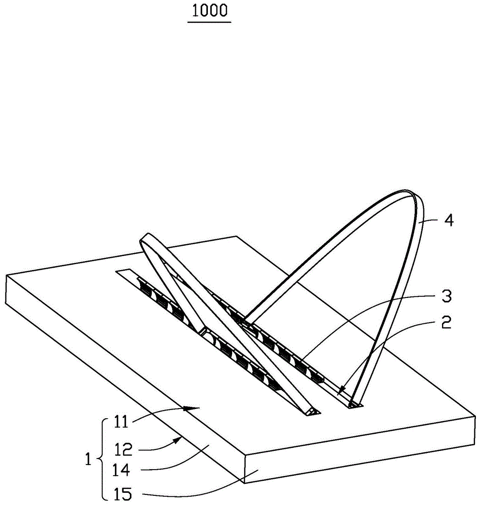
Referring to fig. 1 and fig. 2, a supporting structure 1000 according to an embodiment of the present invention includes a housing 1, a sliding chute 2 disposed on the housing 1 side by side, a track assembly 3 disposed in the sliding chute 2, and a supporting assembly 4. The housing 1 includes a first surface 11 and a second surface 12 opposite to the first surface 11, the first surface 11 is recessed toward the second surface 12 to form a concave surface 13 (as shown in fig. 3), and the concave surface 13 surrounds the sliding slot 2. The supporting assembly 4 includes a positioning portion 41, a sliding portion 42 and an elastic member 43 connecting the positioning portion 41 and the sliding portion 42, the elastic member 43 is disposed in parallel or arched on the first surface 11, the positioning portion 41 is rotatably connected to the inside of the sliding chute 2 or the track assembly 3, and the sliding portion 42 is configured to move back and forth along the track assembly 3, so that the elastic member 43 has a first state and a second state. In the first state, the elastic member 43 is located in the sliding slot 2; in the second state, the elastic member 43 protrudes from the first surface 11 in a curved state. The sliding portion 42 can also be rotatably connected to the track assembly 3, so as to adjust the angle between the elastic member 43 and the first surface 11.
In the present embodiment, the housing 1 includes two opposite first sides 14 and two opposite second sides 15, the first sides 14 are parallel to the extending direction of the sliding chute 2, and the second sides 15 are perpendicular to the extending direction of the sliding chute 2.
In this embodiment, the supporting structure 1000 includes two sliding chutes 2 arranged side by side, two track assemblies 3 are respectively arranged in the two sliding chutes 2, and each track assembly 3 is matched with one supporting assembly 4.
In practical use, when one of the second sides 15 of the housing 1 is placed on a supporting surface, the sliding portion 42 is slid to change the elastic members 43 from the first state to the second state, the two elastic members 43 protrude from the first surface 11 in a bending manner, the two elastic members 43 are supported and placed on the supporting surface together, and the angle of the housing 1 relative to the supporting surface is adjusted by adjusting the degree to which the two elastic members 43 protrude from the first surface 11 in a bending manner and adjusting the included angle of the two elastic members 43 relative to the first surface 11. When the supporting structure 1000 is not used, the sliding part 42 is slid reversely to change the elastic members 43 from the second state to the first state, and the two elastic members 43 are changed from the bent state to the straightened state and fall into the sliding chute 2 again, thereby achieving the purpose of storage.
In other embodiments, the mounting structure 1000 includes a runner 2, which correspondingly includes a track assembly 3 and a support assembly 4.
In actual use, one of the first sides 14 of the housing 1 is placed on a supporting surface and supported by an elastic member 43, the sliding portion 42 is slid to change the elastic member 43 from the first state to the second state, the elastic member 43 is bent to protrude from the first surface 11, and the angle of the housing 1 relative to the supporting surface is adjusted by adjusting the degree to which the elastic member 43 is bent to protrude from the first surface 11 and the included angle of the elastic member 43 relative to the first surface 11. When the supporting structure 1000 is not used, the sliding part 42 is slid reversely to change the elastic member 43 from the second state to the first state, and the elastic member 43 is changed from the bent state to the straightened state and falls into the chute 2 again, thereby achieving the purpose of storage.
In the present embodiment, the housing 1 may be made of plastic.
Referring to fig. 3 again, with reference to fig. 2, the sliding chute 2 is substantially an arc-shaped chute structure, and the sliding chute 2 includes a chute body 21 and a notch 22, where the notch 22 is communicated with the chute body 21 and is located on the first surface 11. The edge of the cross section of the chute body 21 in the direction perpendicular to the extending direction of the chute 2 is arc-shaped, that is, the cross section of the concave surface 13 is arc-shaped, and the radian corresponding to the arc is greater than 180 °, so that the size b of the notch 22 in the direction perpendicular to the extending direction of the chute 2 is smaller than the size c of the chute body 21. The above design is to make the positioning part 41 and the sliding part 42 on the supporting component 4 engaged in the groove body 21 and not fall off. The chute 2 has a simple structure and is easy to form.
Referring to fig. 3 in combination with fig. 2, the chute 2 includes two areas, one area is used for mounting the track assembly 3, and the other area is used for mounting the positioning portion 41. Specifically, a positioning block 23 is disposed in the sliding slot 2, and the positioning block 23 is embedded into one end of the slot body 21 and forms a positioning slot 24 together with the slot body 21. The positioning portion 41 can be snapped into the positioning groove 24, due to the existence of the positioning block 23, the positioning portion 41 can be limited in the positioning groove 24 and cannot move along the extending direction of the slot body 21, but the positioning portion 41 can be in the positioning groove 24 and can rotate along a plane perpendicular to the extending direction of the slot body 21.
In other embodiments, the sliding chute 2 does not need to be divided into two areas, the track assembly 3 can cover all the sliding chutes 2, and the positioning portion 41 can also be directly connected in the track assembly 3 in a rotatable manner, on one hand, the track assembly 3 can limit the positioning portion 41, and on the other hand, the positioning portion 41 can also rotate in the track assembly 3 along a plane perpendicular to the extending direction of the chute body 21. In this embodiment, the chute 2 does not need to form an area for installing the positioning portion 41, and the forming is simpler, and only the positioning portion 41 needs to be rotatably fixed at one end of the rail assembly 3.
Referring to fig. 4, the track assembly 3 includes a first track 31 and a second track 32, and the sliding portion 42 is configured to reciprocate along the first track 31 and the second track 32, so that the elastic member 43 has a first state and a second state. The sliding part 42 can rotate in the second rail 32 and is positioned in the first rail 31.
In the present embodiment, the first track 31 includes a first track opening 311, a connecting portion 312 disposed opposite to the first track opening 311, at least one first tooth slot 313 disposed on the connecting portion 312, and a plurality of second tooth slots 314 disposed on two sides of the connecting portion 312. The first and second slots 313 and 314 are opened toward the central axis a of the track assembly 3.
In this embodiment, the first rail 31 may have an arc-shaped structure, and the first rail 31 may be embedded in the sliding chute 2 of the arc-shaped structure, so that the outer diameter of the first rail 31 is slightly smaller than the inner diameter of the sliding chute 2. And the first track opening 311 of the first track 31 coincides with the notch 22 of the chute 2.
In this embodiment, the first rail 31 is made of plastic or metal.
In this embodiment, as shown in fig. 3 and 4, the number of the first tooth slots 313 is two, the two first tooth slots 313 are symmetrically disposed on two sides of the connecting portion 312, the symmetric surfaces of the two first tooth slots 313 are perpendicular to the first surface 11, two ends of the first tooth slot 313 along the direction parallel to the central axis a are respectively provided with a first opening 315, and the sliding portion 42 can slide into the first tooth slot 313 through one of the first openings 315 and slide out of the first tooth slot 313 through the other first opening 315 to enter the second rail 32.
In this embodiment, the first tooth space 313 has a V-shaped structure along a cross section perpendicular to the central axis a, and the V-shaped structure has a large opening, so that the sliding portion 42 can be easily inserted into the first tooth space 313. Of course, the first tooth slot 313 may be designed in other structures (such as rectangular slot or arc slot).
In this embodiment, referring to fig. 3 and fig. 4 again, the plurality of second tooth slots 314 are equally divided into two groups, and the two groups of second tooth slots 314 are respectively symmetrically disposed on two sides of the connecting portion 312, wherein the second tooth slots 314 located on two sides of the connecting portion 312 are disposed opposite to each other two by two, that is, the two second tooth slots 314 disposed opposite to each other are axisymmetrical with respect to the central axis a. A second opening 316 is disposed at an end of the second tooth slot 314 close to the positioning portion 41, and a blocking piece 317 is disposed at an end of the second tooth slot 314 away from the second opening 316. When the sliding portion 42 rotates into the second tooth groove 314, the sliding portion 42 can slide into the second tooth groove 314 through the second opening 316, and the blocking piece 317 can prevent the sliding portion 42 from coming out of the second tooth groove 314 under the action of the elastic restoring force of the elastic member 43, so that the sliding portion 42 is fixed in the second tooth groove 314. It is understood that the end of the second slot 314 where the blocking piece 317 is disposed may be closed or partially closed, as long as the function of preventing the sliding portion 42 from falling out of the second slot 314 is achieved.
In this embodiment, the second tooth space 314 has a V-shaped structure along a cross section perpendicular to the central axis a, and the V-shaped structure has a large opening to facilitate the sliding portion 42 to be inserted into the second tooth space 314. Of course, the second tooth slot 314 can be designed with other structures (such as rectangular slot or arc slot).
Referring to fig. 5, referring to fig. 3, the second track 32 includes a track body 321, a second track port 322 disposed on the track body 321, and baffles 323 disposed on the track body 321 and at two sides of the second track port 322. The blocking plate 323 has one end connected to the rail body 321 and the other end extending toward the inside of the second rail 32, for preventing the sliding part 42 from falling off the second rail 32. The second rail 32 penetrates the first rail 31, so that the second rail opening 322 penetrates the first rail opening 311, and the sliding portion 42 can be ensured to move smoothly in the first rail 31 and the second rail 32.
In this embodiment, the rail body 321 is an arc structure, and the second rail 32 can be embedded in the sliding chute 2 of the arc structure, so the outer diameter of the second rail 32 needs to be slightly smaller than the inner diameter of the sliding chute 2.
In this embodiment, the second rail 32 is made of plastic or metal.
In the present embodiment, the surface of the rail body 321 facing the central axis a is provided with a coating (not shown) for reducing frictional resistance during rotation or sliding of the sliding part 42, so as to improve the smoothness of rotation or sliding of the sliding part 42.
Referring to fig. 6, the positioning portion 41 includes a positioning body 411, a first sidewall 412 disposed on a side of the positioning body 411 facing the elastic element 43, and a first engaging groove 413 disposed on the first sidewall 412, the first sidewall 412 is disposed perpendicular to the first surface 11, an extending direction of the first engaging groove 413 is parallel to the first surface 11, and an end of the elastic element 43 close to the positioning portion 41 is engaged with the first engaging groove 413 and can reciprocate along the first engaging groove 413.
In this embodiment, the positioning portion 41 is substantially a cylinder, and the diameter of the cylinder is slightly smaller than the inner diameter of the positioning slot 24, so that the positioning portion 41 can be inserted into the positioning slot 24 and can rotate in the positioning slot 24.
In this embodiment, the positioning portion 41 further includes a first bottom wall 414, the first bottom wall 414 and the first side wall 412 are connected together to form a step, an included angle between the first bottom wall 414 and the first side wall 412 is greater than or equal to 90 °, and is preferably 90 °, and the cooperation between the first bottom wall 414 and the first side wall 412 facilitates the elastic member 43 to be more stable during the process of straightening and bending.
In the present embodiment, the positioning portion 41 may be made of plastic.
Referring to fig. 7, the sliding portion 42 includes a sliding block 421, two tooth portions 422 symmetrically disposed on the sliding block 421, a second side wall 423 disposed on a side of the sliding block 421 facing the elastic element 43, and a second engaging groove 424 disposed on the second side wall 423. The second sidewall 423 is disposed perpendicular to the first surface 11, and the extending direction of the second engaging groove 424 is parallel to the first surface 11. One end of the elastic element 43 close to the sliding part 42 can be clamped into the second slot 424 and can move along the second slot 424. The two teeth 422 are respectively used for being clamped into the two first tooth slots 313 and moving along the first tooth slots 313, and the two teeth 422 are also respectively used for being clamped into the two second tooth slots 314 which are symmetrically arranged and moving along the second tooth slots 314. When the tooth portion 422 is slid into the second slot 314 from the second opening 316, the blocking piece 317 blocks the tooth portion 422, thereby fixing the sliding portion 42 in the second slot 314.
In this embodiment, in order to allow the tooth 422 to be easily engaged with the first slot 313 or the second slot 314, the dimension of the tooth 422 in the direction perpendicular to the central axis a is smaller than the dimensions of the first slot 313 and the second slot 314.
In the present embodiment, the tooth 422 has a V-shaped cross section perpendicular to the central axis a, but may have other shapes that can be matched with the first slot 313 or the second slot 314.
In this embodiment, the sliding block 421 is substantially a cylinder structure, and the diameter of the cylinder is slightly smaller than the inner diameter of the first track 31 and the second track 32, so that the sliding block 421 can be embedded in the first track 31 and the second track 32 and can move in the first track 31 and the second track 32.
In this embodiment, the sliding portion 42 further includes a second bottom wall 425, the second bottom wall 425 and the second side wall 423 are connected together to form a step, an included angle between the second bottom wall 425 and the second side wall 423 is greater than or equal to 90 °, and is preferably 90 °, and the cooperation between the second bottom wall 425 and the second side wall 423 facilitates the elastic member 43 to be more stable during the straightening and bending processes.
In the present embodiment, the material of the sliding portion 42 may be plastic.
Referring to fig. 8, the elastic element 43 includes an elastic strip 431 and engaging portions 432 disposed at two ends of the elastic strip 431, where the engaging portions 432 include two fixing bases 4321 connected to the elastic strip 431, a rotating shaft 4322 disposed between the two fixing bases 4321, a shaft sleeve 4323 sleeved on the rotating shaft 4322, and a clamping block 4324 disposed on the shaft sleeve 4323, and the clamping block 4324 is used for being clamped into the first clamping groove 413 or the second clamping groove 424 and can move in the first clamping groove 413 or the second clamping groove 424. The rotation shaft 4322 can rotate in the sleeve 4323, so as to drive the elastic strip 431 to rotate relative to the sleeve 4323.
In the present embodiment, the elastic strip 431 may be made of plastic or rubber, or may be made of metal, and the elastic strip 431 may be in the form of a sheet or other shape (for example, a rod) capable of stably supporting the housing 1.
Referring to fig. 1 again, referring to fig. 2 in combination, when the bracket structure 1000 is needed, the sliding part 42 is pushed to move in the first tooth slot 313 and the second tooth slot 32 of the first rail 31 along the direction parallel to the central axis a, so that the elastic element 43 is convexly bent toward the direction away from the first surface 11, when the preset bending angle is reached, the sliding part 42 is slid into the second rail 32, the elastic element 43 is pulled to rotate the sliding part 42 in the second rail 32 by a certain angle, at this time, the positioning part 41 is also driven by the elastic element 43 to rotate in the positioning slot 24, so that the elastic element 43 is obliquely arranged relative to the housing 1, and when the inclination angles of the two elastic elements 43 reach the required supporting angle, the tooth part 422 of the sliding part 42 is clamped into the second tooth slot 314 corresponding to the first rail 31 to realize fixing.
Referring to fig. 9 again, referring to fig. 2 and fig. 3 in combination, when the supporting frame structure 1000 is not needed, the sliding portion 42 can be reversely withdrawn from the second tooth groove 314 and enter the second rail 32, and the selected angle of the elastic element 43 is adjusted to make the sliding portion 42 enter the first tooth groove 313 of the first rail 31 far away from the positioning portion 41 from the second rail 32, and further move towards the direction far away from the positioning portion 41, so that the elastic element 43 is finally straightened and embedded into the rail assembly 3.
Referring to fig. 10, with reference to fig. 2, in order to prevent the sliding portion 42 from accidentally sliding when the elastic member 43 is not in use in the first state, so as to make the elastic member 43 bounce, the supporting structure 1000 further includes a buckle 5, and the buckle 5 is used for fixing the elastic member 43. Specifically, the sliding groove 2 divides the first surface 11 into a first area a and a second area B opposite to each other, the length direction of the buckle 5 is perpendicular to the central axis a, one end of the buckle 5 is fixedly arranged in the first area a, and the other end of the buckle 5 is detachably arranged in the second area B, so that the elastic member 43 is fixed, and the elastic member 43 is prevented from being bent and protruded accidentally. It is understood that two elastic members 43 may be fixed by using one clip 5, and each elastic member 43 may also use one clip 5.
In this embodiment, the latch 5 may be made of soft material such as silicone, and is used to fix the elastic member 43 when it is completely embedded in the track assembly 3, so that it will not protrude.
The support structure 1000 that this application passed through can be a direct setting on the cell-phone for support the cell phone stand of cell-phone, casing 1 is a part of cell-phone promptly, and support structure 1000 also can be the cell-phone protective housing of cover on the cell-phone, and casing 1 is a part of cell-phone protective housing promptly, and horizontal and vertical multi-angle's regulation can be realized to this support, and can strengthen the control to the cell-phone when needs one hand to hold, makes it can not drop. It will be appreciated that the support structure 1000 may also be used for other support purposes.
The present invention also provides an electronic device (not shown) comprising a support structure 1000 as described above.
In conclusion, the support structure provided by the invention utilizes the matching of the track assembly and the support assembly to adjust the bending degree of the elastic piece and the included angle between the elastic piece and the first surface, so that the aim of adjusting the support structure in multiple angles can be fulfilled, and convenience can be brought to a user; in addition, the support structure is simple in integral structure, light in weight and convenient to carry.