CN115242583B - A Passive Estimation Method of Channel Impulse Response Based on Horizontal Line Array - Google Patents
A Passive Estimation Method of Channel Impulse Response Based on Horizontal Line Array Download PDFInfo
- Publication number
- CN115242583B CN115242583B CN202210891314.XA CN202210891314A CN115242583B CN 115242583 B CN115242583 B CN 115242583B CN 202210891314 A CN202210891314 A CN 202210891314A CN 115242583 B CN115242583 B CN 115242583B
- Authority
- CN
- China
- Prior art keywords
- array
- frequency domain
- array element
- channel impulse
- impulse response
- Prior art date
- Legal status (The legal status is an assumption and is not a legal conclusion. Google has not performed a legal analysis and makes no representation as to the accuracy of the status listed.)
- Active
Links
Images


Classifications
-
- H—ELECTRICITY
- H04—ELECTRIC COMMUNICATION TECHNIQUE
- H04L—TRANSMISSION OF DIGITAL INFORMATION, e.g. TELEGRAPHIC COMMUNICATION
- H04L25/00—Baseband systems
- H04L25/02—Details ; arrangements for supplying electrical power along data transmission lines
- H04L25/0202—Channel estimation
- H04L25/0212—Channel estimation of impulse response
-
- H—ELECTRICITY
- H04—ELECTRIC COMMUNICATION TECHNIQUE
- H04B—TRANSMISSION
- H04B11/00—Transmission systems employing ultrasonic, sonic or infrasonic waves
-
- H—ELECTRICITY
- H04—ELECTRIC COMMUNICATION TECHNIQUE
- H04B—TRANSMISSION
- H04B13/00—Transmission systems characterised by the medium used for transmission, not provided for in groups H04B3/00 - H04B11/00
- H04B13/02—Transmission systems in which the medium consists of the earth or a large mass of water thereon, e.g. earth telegraphy
-
- Y—GENERAL TAGGING OF NEW TECHNOLOGICAL DEVELOPMENTS; GENERAL TAGGING OF CROSS-SECTIONAL TECHNOLOGIES SPANNING OVER SEVERAL SECTIONS OF THE IPC; TECHNICAL SUBJECTS COVERED BY FORMER USPC CROSS-REFERENCE ART COLLECTIONS [XRACs] AND DIGESTS
- Y02—TECHNOLOGIES OR APPLICATIONS FOR MITIGATION OR ADAPTATION AGAINST CLIMATE CHANGE
- Y02D—CLIMATE CHANGE MITIGATION TECHNOLOGIES IN INFORMATION AND COMMUNICATION TECHNOLOGIES [ICT], I.E. INFORMATION AND COMMUNICATION TECHNOLOGIES AIMING AT THE REDUCTION OF THEIR OWN ENERGY USE
- Y02D30/00—Reducing energy consumption in communication networks
- Y02D30/70—Reducing energy consumption in communication networks in wireless communication networks
Landscapes
- Engineering & Computer Science (AREA)
- Computer Networks & Wireless Communication (AREA)
- Signal Processing (AREA)
- Power Engineering (AREA)
- Measurement Of Velocity Or Position Using Acoustic Or Ultrasonic Waves (AREA)
Abstract
Description
技术领域Technical Field
本发明属于水声阵列信号处理、水声信道脉冲响应估计、水声探测和声纳技术领域,具体地说,涉及一种基于水平线列阵的信道脉冲响应被动估计方法。The invention belongs to the technical fields of underwater acoustic array signal processing, underwater acoustic channel impulse response estimation, underwater acoustic detection and sonar, and in particular, relates to a channel impulse response passive estimation method based on a horizontal line array.
背景技术Background Art
根据信号与系统理论,水声信号的频谱在数学上可表示为声源频谱与信道脉冲响应函数频谱(也被称为格林函数)的乘积。信道脉冲响应包含了信道的频散和多途等特征,可被应用于水声环境参数反演、声源定位等问题。提取水声信号中的信道脉冲响应可进一步实现与声源频谱的解耦,去除信道的影响并恢复声源信号,这可被应用于水声通信和水下目标识别等领域。According to signal and system theory, the spectrum of an underwater acoustic signal can be mathematically expressed as the product of the source spectrum and the channel impulse response function spectrum (also known as Green's function). The channel impulse response contains characteristics such as channel dispersion and multipath, and can be applied to problems such as underwater acoustic environment parameter inversion and sound source location. Extracting the channel impulse response from the underwater acoustic signal can further achieve decoupling from the source spectrum, remove the influence of the channel and restore the source signal, which can be applied to underwater acoustic communication and underwater target recognition.
一般来说,可以使用人为制造的一些宽带脉冲声源来获得特定水声信道的脉冲响应,如声弹、气枪等。但是,这种获取方式往往要求声源和接收装置是合作性的,因而常用于水声调查实验或主动声纳应用的场景。基于特定声源的信道脉冲响应估计方法,一方面会增加信道脉冲响应估计的人力和物力成本;另一方面也会在环境信息未知、非合作的场景下应用受限,例如当监测环境中只存在像航船这样的机会声源,我们可利用的信号只有声源辐射的随机噪声信号。因此,发展可以通过航船噪声或其它海洋环境噪声来进行信道脉冲响应被动估计的方法将更加具有实际意义和经济效益。Generally speaking, some artificially manufactured broadband pulse sound sources can be used to obtain the impulse response of a specific underwater acoustic channel, such as acoustic bombs, air guns, etc. However, this acquisition method often requires the sound source and the receiving device to be cooperative, and is therefore often used in underwater acoustic survey experiments or active sonar application scenarios. The channel impulse response estimation method based on a specific sound source will, on the one hand, increase the manpower and material costs of channel impulse response estimation; on the other hand, it will also be limited in application in scenarios where environmental information is unknown and non-cooperative. For example, when there are only opportunity sound sources such as ships in the monitoring environment, the only signal we can use is the random noise signal radiated by the sound source. Therefore, it will be more practical and economical to develop a method that can passively estimate the channel impulse response through ship noise or other marine environmental noise.
通过对两个接收器获得的海洋环境噪声进行互相关叠加可以得到接收器之间的信道脉冲响应估计(又叫经验格林函数),但这一方法需要长时间的累积才能获得收敛的结果,使用双垂直阵并结合使用常规波束形成技术可以加速这一收敛过程。但是在浅海中,垂直阵容易受到渔网破坏,其长时间布放的不确定性较大,相比之下使用水平阵的安全性更好。而且对水声目标探测来说,更加有利的是获得目标与接收器之间的信道脉冲响应。基于水平阵的盲解卷积技术可以用于估计接收位置与目标间的信道脉冲响应,并可用于航船噪声的处理,但其估计精度非常依赖于阵元接收信号的信噪比,只有在较高的信噪比条件下才能获得较高精度的估计结果。By cross-correlating and superimposing the ocean environmental noise obtained by the two receivers, the channel impulse response estimation (also called empirical Green's function) between the receivers can be obtained. However, this method requires a long period of accumulation to obtain a converged result. The use of dual vertical arrays combined with conventional beamforming technology can accelerate this convergence process. However, in shallow waters, vertical arrays are easily damaged by fishing nets, and the uncertainty of their long-term deployment is large. In comparison, the use of horizontal arrays is safer. Moreover, for underwater acoustic target detection, it is more advantageous to obtain the channel impulse response between the target and the receiver. The blind deconvolution technology based on the horizontal array can be used to estimate the channel impulse response between the receiving position and the target, and can be used to process ship noise, but its estimation accuracy is very dependent on the signal-to-noise ratio of the array element receiving signal. Only under high signal-to-noise ratio conditions can a high-precision estimation result be obtained.
发明内容Summary of the invention
本发明的目的在于针对上述技术背景,为解决现有方法的不足,本发明提出一种基于水平线列阵的信道脉冲响应被动估计方法。该方法首先对水平阵列接收到的声压信号进行Fourier变换,获得阵元位置-频率域的声强干涉条纹,并提取条纹斜率。然后,提取参考阵元的声压信号的相位,将提取结果依次与其它各阵元接收的声压信号进行互相关。最后,对互相关后的阵列数据,在频域沿着条纹进行波束形成,波束输出即为声源与参考阵元的信道脉冲响应的估计结果。通过沿条纹的相干处理,本发明方法可相比盲解卷积方法在更低的信噪比下获得更高的信道脉冲响应估计精度。The purpose of the present invention is to address the above technical background, and to solve the shortcomings of the existing methods. The present invention proposes a passive estimation method of channel impulse response based on a horizontal linear array. The method first performs Fourier transform on the sound pressure signal received by the horizontal array, obtains the sound intensity interference fringes in the array element position-frequency domain, and extracts the fringes slope. Then, the phase of the sound pressure signal of the reference array element is extracted, and the extracted result is cross-correlated with the sound pressure signals received by other array elements in turn. Finally, the array data after cross-correlation is beamformed along the fringes in the frequency domain, and the beam output is the estimation result of the channel impulse response of the sound source and the reference array element. Through coherent processing along the fringes, the method of the present invention can obtain higher channel impulse response estimation accuracy at a lower signal-to-noise ratio than the blind deconvolution method.
本发明提出了一种基于水平线列阵的信道脉冲响应被动估计方法,该方法包括:The present invention proposes a method for passively estimating a channel impulse response based on a horizontal line array, the method comprising:
利用水平线列阵获取声源时域声压信号,对时域声压信号进行傅里叶(Fourier)变换得到频域声压信号;The time-domain sound pressure signal of the sound source is obtained by using a horizontal line array, and the time-domain sound pressure signal is subjected to Fourier transformation to obtain the frequency-domain sound pressure signal;
对频域声压信号进行处理获得声强干涉条纹,并提取条纹斜率;Process the frequency domain sound pressure signal to obtain the sound intensity interference fringes and extract the fringes slope;
选取参考阵元并提取参考阵元的声压信号的相位,将提取的相位依次与水平线列阵的各阵元接收的频域声压信号进行互相关;Selecting a reference array element and extracting the phase of the sound pressure signal of the reference array element, and cross-correlating the extracted phase with the frequency domain sound pressure signal received by each array element of the horizontal line array in sequence;
对互相关后得到的频域数据,根据提取的干涉条纹斜率信息,在频域沿着条纹进行波束形成得到阵列数据;For the frequency domain data obtained after cross-correlation, according to the extracted interference fringe slope information, beam forming is performed along the fringe in the frequency domain to obtain array data;
对阵列数据进行波束形成得到波束输出,根据波束输出得到声源与参考阵元的信道脉冲响应的估计结果。The array data is beamformed to obtain a beam output, and an estimation result of the channel impulse response between the sound source and the reference array element is obtained according to the beam output.
作为上述技术方案的改进之一,所述利用水平线列阵获取声源时域声压信号,包括:As one of the improvements of the above technical solution, the method of obtaining the time-domain sound pressure signal of the sound source by using the horizontal line array includes:
利用水平线列阵的各阵元接收声源目标辐射的噪声信号或宽带脉冲信号,并进行采样记录得到水平阵接收的时域声压信号。The array elements of the horizontal linear array are used to receive the noise signal or broadband pulse signal radiated by the sound source target, and the time domain sound pressure signal received by the horizontal array is obtained by sampling and recording.
作为上述技术方案的改进之一,所述对频域声压信号进行处理获得声强干涉条纹,并提取条纹斜率,包括:As one of the improvements of the above technical solution, the processing of the frequency domain sound pressure signal to obtain the sound intensity interference fringes and extracting the fringes slope includes:
对频域声压信号进行处理得到声强数据;Processing the frequency domain sound pressure signal to obtain sound intensity data;
对声强数据进行处理获得在阵元位置-频率域上的强度分布谱图,并利用图像处理方法提取强度分布谱图中干涉条纹的斜率。The sound intensity data is processed to obtain the intensity distribution spectrum in the array element position-frequency domain, and the slope of the interference fringes in the intensity distribution spectrum is extracted using image processing methods.
作为上述技术方案的改进之一,所述得到的声强数据I,表达式为:As one of the improvements of the above technical solution, the obtained sound intensity data I is expressed as:
I=[In]N×1 I=[I n ] N×1
In=|Pn|2 I n = |P n | 2
其中,[·]N×1表示阵列为N×1,N为阵元总数,n为阵元编号,n=1,2,…,N,In表示第n个阵元的声强数据,Pn表示第n个阵元的频域信号。Wherein, [·] N×1 indicates that the array is N×1, N is the total number of array elements, n is the array element number, n=1, 2, …, N, I n indicates the sound intensity data of the nth array element, and P n indicates the frequency domain signal of the nth array element.
作为上述技术方案的改进之一,所述图像处理方法为霍夫变换(Hough变换)或拉东变换(Radon变换)。As one of the improvements of the above technical solution, the image processing method is Hough transform or Radon transform.
作为上述技术方案的改进之一,所述选取参考阵元并提取参考阵元的声压信号的相位,将提取的相位依次与其它各阵元接收的声压信号进行互相关,包括:As one of the improvements of the above technical solution, the step of selecting a reference array element and extracting the phase of the sound pressure signal of the reference array element, and cross-correlating the extracted phase with the sound pressure signals received by other array elements in sequence, includes:
选择第x个阵元作为参考阵元,x=1,2,…,N,N为阵元总数;Select the xth array element as the reference array element, x = 1, 2, ..., N, N is the total number of array elements;
提取第x个阵元接收的频域信号的相位φx=phase(Px);Extract the phase φ x =phase(P x ) of the frequency domain signal received by the x-th array element;
将第x个阵元频域信号的相位φx与N个阵元接收的频域信号做互相关,得到互相关后的频域数据R,表达式为:The phase φ x of the frequency domain signal of the xth array element is cross-correlated with the frequency domain signals received by N array elements to obtain the frequency domain data R after cross-correlation, which is expressed as:
R=[Rn]N×1 R=[R n ] N×1

其中,n为阵元编号,n=1,2,…,N,[·]N×1表示阵列为N×1,x为选取的参考阵元的编号,Rn表示将第x个阵元频域信号的相位φx与第n个阵元接收的频域信号Pn做互相关后的频域数据,*表示共轭操作。Wherein, n is the array element number, n=1,2,…,N, [·] N×1 indicates that the array is N×1, x is the number of the selected reference array element, Rn indicates the frequency domain data after cross-correlating the phase φx of the frequency domain signal of the xth array element with the frequency domain signal Pn received by the nth array element, and * indicates a conjugate operation.
作为上述技术方案的改进之一,所述对阵列数据进行波束形成得到波束输出

其中,


作为上述技术方案的改进之一,所述构造的波束形成的权系数w,表达式为:As one of the improvements of the above technical solution, the weight coefficient w of the constructed beamforming is expressed as:
w=[wn]N×1 w=[ wn ] N×1

其中,wn为构造的对应第n个阵元的波束形成的权系数,j为虚数单位,e为自然常数,ψ(n)为干涉条纹所对应信号的角频率,D(n)为第n个阵元与参考阵元的间距,cref为选取的参考声速。Wherein, wn is the weight coefficient of the constructed beamforming corresponding to the nth array element, j is an imaginary unit, e is a natural constant, ψ(n) is the angular frequency of the signal corresponding to the interference fringes, D(n) is the distance between the nth array element and the reference array element, and cref is the selected reference sound velocity.
作为上述技术方案的改进之一,所述声源与参考阵元的信道脉冲响应的估计结果,通过波束输出的强度最大值来获得,包括:目标声源与参考阵元之间的信道脉冲响应频域信号G和目标声源与参考阵元之间的信道脉冲响应时域信号g;As one of the improvements of the above technical solution, the estimation result of the channel impulse response between the sound source and the reference array element is obtained by the maximum intensity of the beam output, including: a frequency domain signal G of the channel impulse response between the target sound source and the reference array element and a time domain signal g of the channel impulse response between the target sound source and the reference array element;
G的表达式为:The expression of G is:
G=b(θs)G=b(θ s )
其中,b(θs)满足


g通过对G进行Fourier(傅里叶)反变换得到。g is obtained by performing inverse Fourier transform on G.
本发明与现有技术相比优点在于:Compared with the prior art, the present invention has the following advantages:
1、本发明的方法基于水平阵进行信道脉冲响应被动估计:1. The method of the present invention performs passive estimation of channel impulse response based on a horizontal array:
与现有技术中使用垂直阵的方法相比更加适合在浅海长久布放;Compared with the method of using vertical array in the prior art, it is more suitable for long-term deployment in shallow waters;
与基于两个接收器的方法相比,基于水平阵的方法可以使用波束形成技术来加快信道脉冲响应估计结果的收敛速度,降低对信号累积时间长度的依赖;Compared with the method based on two receivers, the method based on the horizontal array can use beamforming technology to speed up the convergence of the channel impulse response estimation results and reduce the dependence on the length of signal accumulation time;
利用阵列信号处理带来的增益,也可以提高对接收信号信噪比的宽容度,增加方法对不同信噪比信号的适用性;By utilizing the gain brought by array signal processing, the tolerance to the signal-to-noise ratio of the received signal can also be improved, increasing the applicability of the method to signals with different signal-to-noise ratios;
2、本发明方法利用参考阵元信号与阵列中各阵元信号之间的互相关来去除声源频谱的影响,可以使本发明方法不仅适用于脉冲信号,也适用于随机噪声信号;2. The method of the present invention utilizes the cross-correlation between the reference array element signal and the array element signals to remove the influence of the sound source spectrum, so that the method of the present invention is applicable not only to pulse signals but also to random noise signals;
3、现有技术中的基于水平阵的水声信号盲解卷积方法,其幅度因子是通过相同频率的阵列信号之间的非相干叠加获得,信道脉冲响应是从单阵元接收信号中引入;3. In the prior art, the blind deconvolution method of underwater acoustic signals based on horizontal arrays is used, in which the amplitude factor is obtained by incoherent superposition of array signals of the same frequency, and the channel impulse response is introduced from the received signal of a single array element;
本发明方法沿着干涉条纹选出进行波束形成的互相关数据,这一处理方式使得本发明方法可以更好地保持信号之间的相关性和幅度一致性;The method of the present invention selects cross-correlation data for beamforming along the interference fringes. This processing method enables the method of the present invention to better maintain the correlation and amplitude consistency between signals.
本发明方法的信道脉冲响应是经过沿条纹的阵列信号处理得到,这能够更加有效利用阵增益,更好地抑制背景噪声对估计结果的影响;The channel impulse response of the method of the present invention is obtained by array signal processing along the stripes, which can more effectively utilize the array gain and better suppress the influence of background noise on the estimation result;
以上特性使得本发明方法相比基于水平阵的水声信号盲解卷积方法可以在更低的信噪比下获得更好的信道脉冲响应估计精度。The above characteristics enable the method of the present invention to obtain better channel impulse response estimation accuracy at a lower signal-to-noise ratio than the blind deconvolution method of underwater acoustic signals based on a horizontal array.
附图说明BRIEF DESCRIPTION OF THE DRAWINGS
图1是本发明方法一种基于水平线列阵的信道脉冲响应被动估计方法的流程图;FIG1 is a flow chart of a method for passively estimating a channel impulse response based on a horizontal line array according to the present invention;
图2是本发明方法在针对水声目标辐射噪声的实施例中参考阵元采集和记录的声压信号时域波形;FIG2 is a time domain waveform of a sound pressure signal collected and recorded by a reference array element in an embodiment of the method of the present invention for underwater acoustic target radiation noise;
图3是本发明方法在针对水声目标辐射噪声的实施例中由接收信号获得的阵元位置-频率域声强干涉条纹及条纹斜率提取结果;FIG3 is a result of extracting the acoustic intensity interference fringes and fringe slopes in the array element position-frequency domain obtained from the received signal in an embodiment of the method of the present invention for underwater acoustic target radiation noise;
图4是本发明方法在针对水声目标辐射噪声的实施例中不同波束扫描角度和信号频率的波束输出强度;FIG4 is a diagram showing beam output intensities at different beam scanning angles and signal frequencies in an embodiment of the method of the present invention for underwater acoustic target radiation noise;
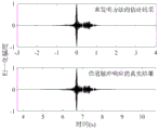
图5是本发明方法在针对水声目标辐射噪声的实施例中的信道脉冲响应估计结果与真实信道脉冲响应的时域波形对比;FIG5 is a time domain waveform comparison of the channel impulse response estimation result and the real channel impulse response in the embodiment of the method of the present invention for underwater acoustic target radiation noise;
图6是本发明方法在针对水声目标发射的宽带调频脉冲信号的实施例中参考阵元采集和记录的声压信号时域波形;FIG6 is a time domain waveform of a sound pressure signal collected and recorded by a reference array element in an embodiment of the method of the present invention for transmitting a broadband frequency modulated pulse signal to an underwater acoustic target;
图7是本发明方法在针对水声目标发射的宽带调频脉冲信号的实施例中由接收信号获得的阵元位置-频率域声强干涉条纹及条纹斜率提取结果;7 is a diagram showing the extraction results of the array element position-frequency domain acoustic intensity interference fringes and fringes slope obtained from the received signal in an embodiment of the method of the present invention for a broadband frequency modulated pulse signal transmitted to an underwater acoustic target;
图8是本发明方法在针对水声目标发射的宽带调频脉冲信号的实施例中不同波束扫描角度和信号频率的波束输出强度;FIG8 is a diagram showing beam output intensities at different beam scanning angles and signal frequencies in an embodiment of a broadband frequency modulated pulse signal transmitted to an underwater acoustic target by the method of the present invention;
图9是本发明方法在针对水声目标发射的宽带调频脉冲信号的实施例中的信道脉冲响应估计结果与真实信道脉冲响应的时域波形对比;9 is a time domain waveform comparison of the channel impulse response estimation result and the real channel impulse response in the embodiment of the method of the present invention for a broadband frequency modulated pulse signal emitted by an underwater acoustic target;
图10是本发明方法与现有基于水平阵的盲解卷积方法通过不同信噪比条件下接收的目标辐射噪声信号对信道脉冲响应进行估计的精度对比。FIG10 is a comparison of the accuracy of the method of the present invention and the existing horizontal array-based blind deconvolution method in estimating the channel impulse response through the target radiation noise signal received under different signal-to-noise ratio conditions.
具体实施方式DETAILED DESCRIPTION
本发明提出一种基于水平线列阵的信道脉冲响应被动估计方法。该方法首先对水平阵列接收到的声压信号进行Fourier变换,获得阵元位置-频率域的声强干涉条纹,并提取条纹斜率。然后,提取参考阵元的声压信号的相位,将提取结果依次与其它各阵元接收的声压信号进行互相关。最后,对互相关后的阵列数据,在频域沿着条纹进行波束形成,波束输出即为声源与参考阵元的信道脉冲响应的估计结果。本发明方法可被用于宽带脉冲信号和目标辐射噪声信号,而且通过沿条纹的相干处理,本发明方法可在较短时间内获得信道脉冲响应的有效估计结果,并相比盲解卷积方法能够在低信噪比下获得更高的信道脉冲响应估计精度。The present invention proposes a method for passively estimating a channel impulse response based on a horizontal linear array. The method first performs a Fourier transform on the sound pressure signal received by the horizontal array, obtains the sound intensity interference fringes in the array element position-frequency domain, and extracts the fringes slope. Then, the phase of the sound pressure signal of the reference array element is extracted, and the extracted result is cross-correlated with the sound pressure signals received by other array elements in turn. Finally, beamforming is performed along the fringes in the frequency domain for the cross-correlated array data, and the beam output is the estimation result of the channel impulse response of the sound source and the reference array element. The method of the present invention can be used for broadband pulse signals and target radiated noise signals, and through coherent processing along the fringes, the method of the present invention can obtain an effective estimation result of the channel impulse response in a relatively short time, and can obtain a higher channel impulse response estimation accuracy at a low signal-to-noise ratio than the blind deconvolution method.
本方法提供了一种基于水平线列阵的信道脉冲响应被动估计方法,该方法包括如下步骤:The present invention provides a method for passively estimating a channel impulse response based on a horizontal line array, and the method comprises the following steps:
步骤1:对布置于海水或者海底的水平阵的各阵元接收到的水声目标辐射的噪声信号或宽带脉冲信号进行采样记录,得到水平阵接收的时域声压信号p=[pn]N×1,其中N表示阵元总数且N为大于1的整数,n为阵元编号,n满足n=1,2,…,N。Step 1: Sample and record the noise signal or broadband pulse signal radiated by the hydroacoustic target received by each array element of the horizontal array arranged in the sea or seabed, and obtain the time domain sound pressure signal p = [p n ] N × 1 received by the horizontal array, where N represents the total number of array elements and N is an integer greater than 1, n is the array element number, and n satisfies n = 1, 2, ..., N.
然后,对记录的时域声压信号p进行Fourier变换,得到其对应的频域信号P=[Pn]N×1。进一步,得到声强数据I=[In]N×1,其中In=|Pn|2。Then, the recorded time domain sound pressure signal p is subjected to Fourier transformation to obtain its corresponding frequency domain signal P = [P n ] N×1 . Further, sound intensity data I = [I n ] N×1 is obtained, where I n = |P n | 2 .
对获得的声强数据,获得其在阵元位置-频率域上的强度分布谱图,可以利用如Hough变换、Radon变换等图像处理方法提取声强谱中干涉条纹的斜率S。For the acquired sound intensity data, its intensity distribution spectrum in the array element position-frequency domain is obtained, and the slope S of the interference fringes in the sound intensity spectrum can be extracted using image processing methods such as Hough transform and Radon transform.
步骤2:选择第x个阵元作为参考阵元,x=1,2,…,N。提取该阵元接收的频域信号的相位φx=phase(Px)。Step 2: Select the xth array element as the reference array element, x = 1, 2, ..., N. Extract the phase φ x = phase (P x ) of the frequency domain signal received by the array element.
然后,将第x个阵元频域信号的相位φx与其它各阵元接收的频域信号Pn做互相关,得到互相关后的频域数据R=[Rn]N×1,其中
步骤3:依据步骤1中提取的干涉条纹斜率信息,沿着干涉条纹从互相关后的频域数据选出进行波束形成的阵列数据
构造波束形成的权系数w=[wn]N×1,其中Construct the beamforming weight coefficient w = [w n ] N × 1 , where

j为虚数单位,e为自然常数,ω(n)为干涉条纹所对应信号的角频率,D(n)为第n个阵元与参考阵元的间距,
对阵列数据


对目标声源与参考阵元之间的信道脉冲响应频域信号G进行Fourier反变换,得到目标声源与参考阵元之间的信道脉冲响应时域信号g。The frequency domain signal G of the channel impulse response between the target sound source and the reference array element is subjected to inverse Fourier transform to obtain the time domain signal g of the channel impulse response between the target sound source and the reference array element.
以下结合实施例进一步说明本发明所提供的技术方案。The technical solution provided by the present invention is further described below in conjunction with embodiments.
如图1所示,是实施例1-3采用本发明基于水平线列阵的信道脉冲响应被动估计方法来获取估计结果的流程图。As shown in FIG. 1 , it is a flow chart of embodiments 1-3 using the channel impulse response passive estimation method based on horizontal line arrays of the present invention to obtain estimation results.
实施例1.Example 1.
该实施例为针对水声目标辐射噪声的信道脉冲响应估计。仿真参数为:海水深度100m,声速1500m/s,密度1g/cm3,海水无声吸收;海底声速1800m/s,密度1.8g/cm3,海底介质声吸收为0.5dB/λ,λ代表声波波长;声源设定为模拟辐射噪声的高斯白噪声信号源,声源深度为4m;均匀水平接收阵的阵元数为N=501,阵元间隔d=0.5m,布放深度为60m;声源与接收基阵之间的水平距离为10km。仿真中不考虑背景噪声。选择水平阵的第251个阵元作为参考阵元,即x=251。This embodiment is a channel impulse response estimation for the radiation noise of underwater acoustic targets. The simulation parameters are: seawater depth 100m, sound speed 1500m/s, density 1g/ cm3 , no sound absorption in seawater; seabed sound speed 1800m/s, density 1.8g/ cm3 , seabed medium sound absorption 0.5dB/λ, λ represents the wavelength of sound waves; the sound source is set as a Gaussian white noise signal source simulating radiation noise, and the sound source depth is 4m; the number of array elements of the uniform horizontal receiving array is N=501, the array element interval d=0.5m, and the deployment depth is 60m; the horizontal distance between the sound source and the receiving array is 10km. Background noise is not considered in the simulation. The 251st array element of the horizontal array is selected as the reference array element, that is, x=251.
步骤1:对各阵元接收信号进行采集与记录,得到时域声压信号p=[pn]501×1,此时n=1,2,…,501。图2是参考阵元采集和记录的声压信号时域波形数据,即p251。Step 1: Collect and record the received signals of each array element to obtain a time domain sound pressure signal p = [p n ] 501×1 , where n = 1, 2, …, 501. Figure 2 is the time domain waveform data of the sound pressure signal collected and recorded by the reference array element, namely p 251 .
然后,对记录的时域声压信号p进行Fourier变换,得到其对应的频域信号P=[Pn]501×1。进一步,得到声强数据I=[In]501×1,其中In=|Pn|2,获得的阵元位置-频率域声强干涉条纹如图3所示。Then, the recorded time domain sound pressure signal p is Fourier transformed to obtain its corresponding frequency domain signal P = [P n ] 501 × 1 . Further, the sound intensity data I = [I n ] 501 × 1 is obtained, where I n = |P n | 2 , and the obtained array element position-frequency domain sound intensity interference fringes are shown in FIG3 .
对图3所示的声强条纹利用Hough变换图像处理方法提取声强谱中干涉条纹的斜率S,提取结果如图中虚线所示,有S=0.058Hz/m。The slope S of the interference fringes in the sound intensity spectrum is extracted using the Hough transform image processing method for the sound intensity fringes shown in FIG3 . The extraction result is shown by the dotted line in the figure, and S=0.058 Hz/m.
步骤2:提取参考阵元接收频域信号的相位φ251=phase(P251)。然后,将参考阵元频域信号的相位φ251与其它各阵元接收的频域信号Pn做互相关,得到互相关后的频域数据R=[Rn]501×1,其中
步骤3:依据步骤1中提取的干涉条纹斜率信息,沿着干涉条纹从互相关后的频域数据选出进行波束形成的阵列数据
构造波束形成的权系数w=[wn]501×1,其中Construct beamforming weight coefficient w = [w n ] 501 × 1 , where

在本实施例中,ω(n)满足ω(n)=ω0-2πSnd,其中ω0=2πf0,f0∈[690,710]Hz。D(n)=n-251)d,
对阵列数据


实施例2.Example 2.
该实施例为针对水声目标发射的宽带调频脉冲信号的信道脉冲响应函数估计。仿真声源设定为660~740Hz的线性调频信号,脉冲时间宽度为6s,声源深度为4m,其它仿真参数与实施例1相同。同样选择水平阵的第251个阵元作为参考阵元,即x=251。This embodiment is for estimating the channel impulse response function of a broadband frequency modulated pulse signal emitted by an underwater acoustic target. The simulated sound source is set to a linear frequency modulated signal of 660-740 Hz, the pulse time width is 6s, the sound source depth is 4m, and other simulation parameters are the same as those in
步骤1:对各阵元接收信号进行采集与记录,得到时域声压信号p=[pn]501×1。图6是参考阵元采集和记录的声压信号时域波形数据,即p251。Step 1: Collect and record the received signals of each array element to obtain a time domain sound pressure signal p=[p n ] 501×1 . FIG6 is the time domain waveform data of the sound pressure signal collected and recorded by the reference array element, that is, p 251 .
然后,对记录的时域声压信号p进行Fourier变换,得到其对应的频域信号P=[Pn]501×1。进一步,得到声强数据I=[In]501×1,获得的阵元位置-频率域声强干涉条纹如图7所示。Then, the recorded time domain sound pressure signal p is Fourier transformed to obtain its corresponding frequency domain signal P = [P n ] 501×1 . Further, the sound intensity data I = [I n ] 501×1 is obtained, and the obtained array element position-frequency domain sound intensity interference fringes are shown in FIG7 .
对图7所示的声强条纹利用Hough变换图像处理方法提取声强谱中干涉条纹的斜率S,提取结果如图中虚线所示,有S=0.058Hz/m。The slope S of the interference fringes in the sound intensity spectrum is extracted using the Hough transform image processing method for the sound intensity fringes shown in FIG. 7 . The extraction result is shown by the dotted line in the figure, and S=0.058 Hz/m.
步骤2:提取参考阵元接收频域信号的相位φ251=phase(P251),然后得到互相关后的频域数据R=[Rn]501×1,其中
步骤3:依据步骤1中提取的干涉条纹斜率信息,沿着干涉条纹从互相关后的频域数据选出进行波束形成的阵列数据
构造波束形成的权系数w=[wn]501×1,其中Construct beamforming weight coefficient w = [w n ] 501 × 1 , where

在本实施例中,ω(n)满足ω(n)=ω0-2πSnd,其中ω0=2πf0,f0∈[690,710]Hz。D(n)=(n-251)d,
对阵列数据


实施例3.Example 3.
该实施例为针对水声目标辐射噪声的信道脉冲响应函数估计,与现有基于水平阵的盲解卷积方法在不同信噪比下进行估计精度的对比。仿真中考虑背景噪声为高斯白噪声,水平阵接收信号的信噪比变化范围设定为-30~30dB,其它仿真参数与实施例1相同。This embodiment is a comparison of the estimation accuracy of the channel impulse response function for underwater acoustic target radiation noise and the existing blind deconvolution method based on the horizontal array under different signal-to-noise ratios. In the simulation, the background noise is considered to be Gaussian white noise, the signal-to-noise ratio range of the horizontal array received signal is set to -30 to 30 dB, and the other simulation parameters are the same as those in Example 1.
每一信噪比条件下,按照实施例1所述的步骤使用本发明方法获得声源与参考阵元之间信道脉冲响应的估计结果,并计算与真实信道脉冲响应的相关系数;同时,用基于水平阵的盲解卷积方法也获得声源与参考阵元之间信道脉冲响应的估计结果,并计算与真实信道脉冲响应的相关系数。将两种方法在不同信噪比下的相关系数统计如图10所示,可见本发明方法相比基于水平阵的水声信号盲解卷积方法可以在更低的信噪比下获得更好的信道脉冲响应估计精度,能够更加有效利用阵增益,更好地抑制背景噪声对估计结果的影响,提高对接收信号信噪比的宽容度。Under each signal-to-noise ratio condition, the method of the present invention is used according to the steps described in Example 1 to obtain the estimation result of the channel impulse response between the sound source and the reference array element, and the correlation coefficient with the real channel impulse response is calculated; at the same time, the blind deconvolution method based on the horizontal array is also used to obtain the estimation result of the channel impulse response between the sound source and the reference array element, and the correlation coefficient with the real channel impulse response is calculated. The correlation coefficients of the two methods under different signal-to-noise ratios are statistically shown in Figure 10. It can be seen that the method of the present invention can obtain better channel impulse response estimation accuracy at a lower signal-to-noise ratio than the blind deconvolution method of underwater acoustic signals based on the horizontal array, can more effectively utilize the array gain, better suppress the influence of background noise on the estimation result, and improve the tolerance to the signal-to-noise ratio of the received signal.
从上述对本发明的具体描述可以看出,本发明方法实现了在更低的信噪比下获得更高的信道脉冲响应估计精度。It can be seen from the above specific description of the present invention that the method of the present invention achieves higher channel impulse response estimation accuracy at a lower signal-to-noise ratio.
最后所应说明的是,以上实施例仅用以说明本发明的技术方案而非限制。尽管参照实施例对本发明进行了详细说明,本领域的普通技术人员应当理解,对本发明的技术方案进行修改或者等同替换,都不脱离本发明技术方案的精神和范围,其均应涵盖在本发明的权利要求范围当中。Finally, it should be noted that the above embodiments are only used to illustrate the technical solutions of the present invention and are not intended to limit the present invention. Although the present invention is described in detail with reference to the embodiments, it should be understood by those skilled in the art that any modification or equivalent replacement of the technical solutions of the present invention does not depart from the spirit and scope of the technical solutions of the present invention and should be included in the scope of the claims of the present invention.
Claims (4)


Priority Applications (1)
| Application Number | Priority Date | Filing Date | Title |
|---|---|---|---|
| CN202210891314.XA CN115242583B (en) | 2022-07-27 | 2022-07-27 | A Passive Estimation Method of Channel Impulse Response Based on Horizontal Line Array |
Applications Claiming Priority (1)
| Application Number | Priority Date | Filing Date | Title |
|---|---|---|---|
| CN202210891314.XA CN115242583B (en) | 2022-07-27 | 2022-07-27 | A Passive Estimation Method of Channel Impulse Response Based on Horizontal Line Array |
Publications (2)
| Publication Number | Publication Date |
|---|---|
| CN115242583A CN115242583A (en) | 2022-10-25 |
| CN115242583B true CN115242583B (en) | 2023-05-26 |
Family
ID=83674766
Family Applications (1)
| Application Number | Title | Priority Date | Filing Date |
|---|---|---|---|
| CN202210891314.XA Active CN115242583B (en) | 2022-07-27 | 2022-07-27 | A Passive Estimation Method of Channel Impulse Response Based on Horizontal Line Array |
Country Status (1)
| Country | Link |
|---|---|
| CN (1) | CN115242583B (en) |
Families Citing this family (2)
| Publication number | Priority date | Publication date | Assignee | Title |
|---|---|---|---|---|
| CN116400406B (en) * | 2023-04-21 | 2023-12-19 | 中国地震局地球物理研究所 | Array-based passive source multi-mode surface wave dispersion curve extraction method |
| CN119541528B (en) * | 2024-10-25 | 2026-04-21 | 中国船舶集团有限公司第七一五研究所 | Broadband array gain forecasting method based on sound field spatial correlation correction |
Citations (2)
| Publication number | Priority date | Publication date | Assignee | Title |
|---|---|---|---|---|
| CN112098983A (en) * | 2020-09-14 | 2020-12-18 | 中国科学院声学研究所 | Shallow sea horizontal array passive positioning method and system based on spatial domain deconvolution processing |
| CN113011006A (en) * | 2021-02-25 | 2021-06-22 | 中国科学院声学研究所 | Target depth estimation method based on cross-correlation function pulse waveform matching |
Family Cites Families (8)
| Publication number | Priority date | Publication date | Assignee | Title |
|---|---|---|---|---|
| CN101335574B (en) * | 2008-07-30 | 2012-09-26 | 哈尔滨工程大学 | Sound shielding method for multipath channel |
| CN105204026A (en) * | 2014-06-13 | 2015-12-30 | 中国人民解放军92232部队 | Single horizontal array passive speed measurement and distance measurement device based on sound field interference fringe and method |
| CN112104579B (en) * | 2020-08-25 | 2021-11-19 | 西安交通大学 | Channel estimation method, system, device and storage medium based on model constraint |
| CN112987004B (en) * | 2021-02-05 | 2023-07-21 | 中国人民解放军国防科技大学 | A surface and underwater target classification method based on horizontal array in shallow sea environment |
| CN113281727B (en) * | 2021-06-02 | 2021-12-07 | 中国科学院声学研究所 | Output enhanced beam forming method and system based on horizontal line array |
| CN113704685B (en) * | 2021-08-09 | 2024-05-31 | 西北工业大学 | A deep-sea blind deconvolution method based on vertical line arrays |
| CN113721245B (en) * | 2021-09-03 | 2024-02-13 | 中国人民解放军国防科技大学 | Seabed horizontal array correction method and processor |
| CN113708808B (en) * | 2021-09-08 | 2023-03-31 | 中国铁道科学研究院集团有限公司 | Narrow beam channel measurement system and method in high-speed mobile scene |
-
2022
- 2022-07-27 CN CN202210891314.XA patent/CN115242583B/en active Active
Patent Citations (2)
| Publication number | Priority date | Publication date | Assignee | Title |
|---|---|---|---|---|
| CN112098983A (en) * | 2020-09-14 | 2020-12-18 | 中国科学院声学研究所 | Shallow sea horizontal array passive positioning method and system based on spatial domain deconvolution processing |
| CN113011006A (en) * | 2021-02-25 | 2021-06-22 | 中国科学院声学研究所 | Target depth estimation method based on cross-correlation function pulse waveform matching |
Also Published As
| Publication number | Publication date |
|---|---|
| CN115242583A (en) | 2022-10-25 |
Similar Documents
| Publication | Publication Date | Title |
|---|---|---|
| CN112269164B (en) | Weak target positioning method based on interferometric structure matching processing in deep-sea reliable acoustic path | |
| CN109283536B (en) | A multi-beam bathymetric sonar water body imaging beamforming method | |
| CN113281727B (en) | Output enhanced beam forming method and system based on horizontal line array | |
| CN109541548B (en) | Air sonar positioning method based on matching field | |
| CN105301580B (en) | A kind of passive detection method based on division battle array cross-spectrum phase difference variance weighted | |
| CN115242583B (en) | A Passive Estimation Method of Channel Impulse Response Based on Horizontal Line Array | |
| CN119044892A (en) | Deep sea target passive positioning method and device by utilizing horizontal array | |
| Wu et al. | Passive source depth estimation using beam intensity striations of a horizontal linear array in deep water | |
| Blomberg et al. | Adaptive sonar imaging using aperture coherence | |
| CN112924926B (en) | A DOA Estimation Method for Multiple Channels | |
| CN119511207A (en) | A method for output sidelobe suppression of ultra-high resolution millimeter-wave radar | |
| CN103513249B (en) | A kind of broadband coherent mold base signal processing method and system | |
| CN115902849B (en) | Deep sea sound source depth estimation method based on beam output intensity resampling | |
| CN113704685B (en) | A deep-sea blind deconvolution method based on vertical line arrays | |
| CN116106879B (en) | Linear array line spectrum coherent accumulation detection method in multi-path environment | |
| CN114374407B (en) | Spatial channel characteristic prediction method, system and storage medium based on m-sequence | |
| CN115236596A (en) | A method of horizontal array signal acquisition based on cross-correlation phase compensation | |
| Liu et al. | Application of striation-based beamforming for enhanced passive azimuth estimation with horizontal line array in shallow water | |
| Santos et al. | Geometric and seabed parameter estimation using a vector sensor array—Experimental results from Makai experiment 2005 | |
| Wang et al. | Passive distributed arrays cross-location algorithm with windowed deconvolution | |
| CN115902853B (en) | Synthetic receiving aperture focusing beam forming method suitable for high-speed submarine surveying and mapping | |
| Xiang-jian et al. | An imaging algorithm for high-speed side-scan sonar based on multi-beam forming technology | |
| Xionghou et al. | High-resolution 2D imaging using MIMO sonar with fourier integral method (FIM) | |
| CN116660910B (en) | A passive positioning method for towed arrays based on broadband matrix filtering | |
| Mueller et al. | Passive HF Noise Interferometry for Sea Surface Estimation |
Legal Events
| Date | Code | Title | Description |
|---|---|---|---|
| PB01 | Publication | ||
| PB01 | Publication | ||
| SE01 | Entry into force of request for substantive examination | ||
| SE01 | Entry into force of request for substantive examination | ||
| GR01 | Patent grant | ||
| GR01 | Patent grant |