Feeding and discharging equipment for test machine and feeding and discharging method
Technical Field
The invention belongs to the technical field of electronic product testing equipment, and particularly relates to a loading and unloading device and a loading and unloading method for a testing machine.
Background
In the production process of electronic elements, tens of times or even hundreds of times of detection is needed, for plate-shaped electronic element products, such as display panels, circuit boards and the like, the transfer modes among test stations are various, generally, small-size products are placed in trays, one or more than one product can be placed in one tray, the trays can be stacked into a plurality of layers so as to facilitate the manual loading and unloading of the trays with a plurality of layers simultaneously, large-size products are placed in a larger placing frame in a single piece, and the single piece is transported independently through a conveyor belt or transported in a stacking manner through a trolley, and the single piece is manually loaded and unloaded.
For the test equipment with the purification grade requirement, the existing test equipment generally sets corresponding machine tables according to the size of a product, the test machine table for loading the stacking tray cannot be used for the product for loading the single sheet, otherwise, the test machine table for loading the single sheet cannot be used for small products on the stacking tray, and the compatibility is poor. As is known, in the appearance test of electronic components, different tests for different products are different in the detection program set by the test machine, and only the corresponding test program needs to be selected according to the product during the test. For test equipment with the grading function, the carrying mechanism needs to shuttle back and forth among the emptying devices, and the arrangement of the emptying devices directly influences the stroke and the carrying efficiency of the carrying mechanism. In addition, the test machine generally needs tens of seconds or even minutes for testing a product, in this time period, the conveying mechanism for loading and unloading is in a stagnation state, and in the loading and unloading time after the test is completed, the test machine is completely in a standby state, and the longer the standby time is, the lower the working efficiency is.
Therefore, it is desirable to provide a loading and unloading apparatus and a loading and unloading method for a testing machine with high compatibility and high working efficiency.
Disclosure of Invention
The invention provides a feeding and discharging device for a test machine, which is high in compatibility, can meet the requirement of feeding and discharging work for testing products and single-chip products in a tray, and provides a specific feeding and discharging method, so that the test frequency can be increased, the test pace is accelerated, and the test efficiency is improved.
Other objects and advantages of the present invention will be further understood from the technical features disclosed in the present invention.
In order to achieve part or all of the purposes or other purposes, the feeding and discharging equipment for the test machine comprises a carrying mechanism, at least four tray frames, a discharging platform for placing a first product and a buffer platform for placing a tested product, wherein the at least four tray frames are respectively an empty tray feeding frame for placing a stacked empty tray, a full tray feeding frame for placing a stacked full tray, a qualified product discharging frame and a defective product discharging frame, and the trays on the tray frames are used for placing a second product, and the second product is different from the first product in size; transport mechanism is located test board front side, the blowing platform is located transport mechanism front side, the buffer memory platform is located between transport mechanism and the test board, empty dish income work or material rest and full dish income work or material rest are located transport mechanism left side, certified products play work or material rest and defective products play work or material rest are located transport mechanism right side, transport mechanism is used for first product is in transport each other between blowing platform, buffer memory platform and the test board, and be used for second product, empty tray are in transport each other between at least four tray racks, buffer memory platform and the test board.
In the production process of circuit boards or panels or other products, small-size products, namely second products, are generally placed in trays for carrying out other transfer of various production and test stations, one product or two or more products can be placed on one tray, and large-size products, namely first products, are transferred in a single piece.
When testing products in the tray, the carrying mechanism takes products to be tested from the tray on the full-tray loading frame to carry out loading, the products are temporarily placed on the buffer storage platform after the test is finished, the carrying mechanism firstly carries out loading again, the standby time of the test machine table is reduced, then the products on the buffer storage platform are discharged into the tray on the qualified product tray frame or the defective product tray frame according to the test result, after the tray on the top layer of the full-tray loading frame is empty, the empty tray is supplemented to the qualified product tray frame or the defective sheet tray frame according to the condition, and if the qualified product tray frame or the defective sheet tray frame does not need to be supplemented with the empty tray, the empty tray is placed on the empty-tray loading frame; when the qualified product tray rack or the defective product tray rack is full of trays, the carrying mechanism supplies the trays on the empty tray feeding rack to the qualified product tray rack or the defective product tray rack with full trays.
When a single-chip product is tested, a product to be tested is placed on the material placing platform, the conveying mechanism feeds the product through the material placing platform, the product is placed on the cache platform after the test is completed, the conveying mechanism firstly feeds the product to be tested on the material placing platform, and then the product on the cache platform is fed onto the material placing platform.
The tray frame, the emptying platform, the cache platform and the testing machine are arranged in the grabbing range of the carrying mechanism, the working processes of the carrying mechanism and the testing machine are debugged and set according to the actual condition of a product to be tested, so that the equipment can be compatible with the testing of the products with different feeding modes, the compatibility and the utilization rate of the testing equipment are improved, the equipment cost is saved, the switching of the machine is avoided, and the working efficiency is improved. Simultaneously transport mechanism is located test board front side, makes blowing platform is located transport mechanism front side, the buffer memory platform is located between transport mechanism and the test board, empty dish income work or material rest and full dish income work or material rest are located transport mechanism left side, certified products play work or material rest and defective products play work or material rest are located transport mechanism right side makes things convenient for the manual work to the unloading of piling up tray, jumbo size product, reduces the motion stroke in transport mechanism stroke range and the work, reduces the whole size of equipment, practices thrift the activity duration. Because the buffer memory platform is close to the distance of the test machine, the transport mechanism can temporarily place the tested product on the buffer memory platform during working, the to-be-tested product is loaded firstly, and then the product on the buffer memory platform is unloaded, so that the stand-by time of the test machine is shortened, and the test efficiency is improved.
Because the carrying mechanism needs to absorb large-size products, small-size products and trays, in order to ensure the stability of the absorption, a first sucking disc and a second sucking disc which are parallel to each other are arranged on the carrying mechanism, first sucking nozzles are arranged on the first sucking disc and the second sucking disc, and a hollow area is arranged in the middle of the first sucking disc; the second sucker is connected with a driving piece and shuttles to the hollow area under the action of the driving piece. When a large-size product is sucked, the first sucking disc is used, and the second sucking disc is positioned above the first sucking disc; the second sucker is used when small-size products are sucked, the second sucker shuttles to the lower side of the first sucker under the action of the driving piece, and when the suckers are sucked, the proper suckers are selected and used according to the sizes of the suckers.
The tray frame comprises a top tray clamping mechanism, a lifting supporting platform and a carrying platform, wherein the top tray clamping mechanism, the lifting supporting platform and the carrying platform are sequentially arranged from top to bottom, the carrying platform is arranged on the frame, the lifting supporting platform is used for clamping and supporting the stacked trays on the carrying platform to rise, the top tray reaches the height of the top tray clamping mechanism, and the top tray clamping mechanism is used for clamping and fixing the top tray, so that the carrying mechanism can conveniently take and place products. The tray frame has realized the automatic operation of tray, and after the whole tests of full pan income frame top layer tray in the product, handling mechanism transfers empty tray as required to certified products play work or defective products play work or material rest, the height of a tray that goes up of lift saddle, the fixed new top layer tray of top tray fixture centre gripping, the same reason, full pan income frame, certified products play work or defective products play work or material rest rise as required or descend the adjustment to pile up the tray position in the course of the work. When the stacking trays in the full tray feeding frame and the empty tray feeding frame rise to a certain height, the carrying platform can be fed again; in a similar way, when the stacking trays on the qualified product discharging frame and the defective product discharging frame reach a certain number, the lifting support table descends, the stacking trays are placed on the carrying platform, and discharging is facilitated.
The carrying platform is of a drawer type structure and is provided with a handle for pushing and pulling, and when the material is taken and placed, the handle is dragged to be pulled out of the carrying platform, so that the operation is convenient; the upper surface of the carrier is provided with a limiting block, so that the placing position of the stacking tray on the carrier is limited, and the interference with the lifting tray and the top tray clamping mechanism is prevented; the lifting saddle comprises two opposite clamping pieces, the clamping pieces move in the opposite direction or in the opposite direction under the drive of the X-direction movement mechanism, and the lifting saddle is driven to move in the lifting direction under the drive of the Z-direction movement mechanism; the top tray clamping mechanism comprises a support and a clamping block movably connected to the support, and the clamping block moves towards or away from the top tray under the driving of the telescopic piece to clamp or release the stacking tray.
The utility model discloses a test machine platform, including buffer memory platform, transport mechanism, code reader, production quality process control, reading mechanism, test board, buffer memory platform side is equipped with the code reader who is used for reading product information, and during operation, transport mechanism will await measuring the product and transfer to code reader below and read the sign indicating number admission information, and the production quality process control of being convenient for reads the sign indicating number and can go on when test board carries out last product inspection, puts back original position after reading the sign indicating number, and when test board test like this, transport mechanism has accomplished reading sign indicating number, unloading work, and the process of rational arrangement provides work efficiency.
In order to adapt to the buffer storage placement of the first product and the second product, the buffer storage platform is provided with different adsorption zones, each adsorption zone is composed of continuous and end-to-end air grooves, air holes for connecting air pipes are formed in the air grooves, and the proper adsorption zones are selected according to the size of the product during work.
The discharging platform is provided with a position-leaning boss for improving the product placing position precision and a sensor for detecting whether the product is placed in place, for large-size testing, a small position error is allowed for the testing machine, the position-leaning boss and the sensor are utilized to guarantee that the large-size product is in the position precision on the discharging platform, the feedback and calculation work of image acquisition is avoided, the equipment cost is saved under the condition of meeting the use requirement, and the work efficiency is improved.
The full-tray feeding frame is characterized in that an image acquisition device is arranged above the full-tray feeding frame and used for acquiring position information of a product to be detected in a top full tray and detecting the appearance of the product, the image acquisition device shoots the product to be detected, the position information of the product to be detected is acquired, a carrying mechanism can conveniently carry out position compensation to obtain the product, the appearance of the product can be detected, namely whether the product has defects such as cracks, fragments, unfilled corners and the like is judged according to the shot image, when the defects exist, the equipment gives an alarm, personnel manually remove the defects and do not continue feeding; for single-sheet product feeding, defects such as cracks, fragments, unfilled corners and the like are judged by manual visual observation.
The method for loading and unloading the products in the stacking tray by using the loading and unloading equipment of the test machine comprises the following steps:
s1, an image acquisition device photographs and positions a product to be detected in a tray on the uppermost layer of a full-tray feeding rack, and detects the appearance of the product;
s2, the carrying mechanism takes the product to be detected according to the product position information, moves to the position below the code reader to read the code, and returns to the original position in the full tray at the uppermost layer after the code reading is finished;
s3, after the product in the testing machine is tested, the conveying mechanism takes out the tested product and places the tested product on the cache platform;
s4, the carrying mechanism takes out the products read by the codes from the top full tray and places the products into a testing machine for feeding;
and S5, the carrying mechanism feeds the products on the cache platform into the trays on the tray rack of the qualified products or the defective products according to the detection result.
The method for loading and unloading the single-chip product by utilizing the loading and unloading equipment of the test machine comprises the following steps:
s1, manually placing a product to be detected on a discharging platform, enabling an inductor to sense the product, and visually detecting the appearance of the product;
s2, the conveying mechanism takes the product to be detected, moves to the position below the code reader to read the code, and returns the product to the discharging platform after the code reading is finished;
s3, after the product in the testing machine is tested, the conveying mechanism takes out the tested product and places the tested product on the cache platform;
s4, the carrying mechanism takes the product to be tested after the code reading from the discharging platform, and places the product to be tested into a testing machine for loading;
s5, the carrying mechanism transfers the products on the cache platform to a discharging platform;
and S6, manually blanking the product on the discharging platform according to the test result.
Compared with the prior art, the invention has the beneficial effects that:
1. according to the feeding and discharging equipment for the testing machine, the tray frame and the discharging platform are integrated, so that the equipment can meet the feeding and discharging work of testing products and single-piece products in the tray in a feeding mode, the compatibility and the utilization rate of the testing machine are improved, the equipment cost is saved, the machine switching is avoided, and the working efficiency is improved;
2. according to the feeding and discharging equipment for the test machine, the discharging platform is positioned on the front side of the carrying mechanism, the buffer storage platform is positioned between the carrying mechanism and the test machine, the empty tray feeding frame and the full tray feeding frame are positioned on the left side of the carrying mechanism, and the qualified product discharging frame and the defective product discharging frame are positioned on the right side of the carrying mechanism, so that the stacking trays and large-size products can be conveniently and manually fed and discharged, the stroke range of the carrying mechanism and the movement stroke in the working process are reduced, the overall size of the equipment is reduced, and the operation time is saved;
3. according to the feeding and discharging equipment for the test machine, the first sucker and the second sucker which are parallel to each other are arranged on the carrying mechanism, the second sucker can move in a lifting mode to shuttle in the hollow area of the first sucker, and a proper sucker can be selected and used according to the size of an object to be sucked, so that the sucking stability is guaranteed;
4. according to the loading and unloading equipment and the loading and unloading method for the test machine, the buffer platform is arranged, so that when the test machine tests, the manipulator can complete code reading work of a next product to be tested and unloading work of a last product to be tested, procedures are reasonably arranged, and working efficiency is improved.
In order to make the aforementioned and other objects, features and advantages of the present invention comprehensible, preferred embodiments accompanied with figures are described in detail below.
Drawings
In order to more clearly illustrate the technical solutions in the specific embodiments of the present invention, the drawings needed to be used in the description of the embodiments will be briefly introduced below, and it is obvious that the drawings described below are only some embodiments of the present invention, and it is obvious for those skilled in the art that other drawings can be obtained according to these drawings without inventive efforts.
Fig. 1 is a schematic structural diagram of a feeding and discharging device for a test machine according to a first embodiment of the present invention;
FIG. 2 is a schematic structural diagram of the test bench of FIG. 1 with the loading and unloading equipment removed from the rack;
FIG. 3 is a schematic view of the track range of the carrying mechanism and the material taking and placing direction of the tray rack in FIG. 1;
fig. 4 is a schematic view of the track range of the carrying mechanism and the material taking and placing direction of the tray rack when the tray rack, the material placing platform and the buffer storage platform are arranged in a line at one side of the carrying mechanism;
FIG. 5 is a schematic view of the track range of the carrying mechanism and the material taking and placing direction of the tray rack when the tray rack, the material placing platform and the buffer platform are circumferentially and uniformly distributed around the carrying mechanism;
FIG. 6 is a schematic structural view of the carrying mechanism in FIG. 1;
FIG. 7 is an enlarged view of FIG. 6 at A;
FIG. 8 is a schematic structural view of the tray rack of FIG. 1;
FIG. 9 is an enlarged view at B in FIG. 8;
FIG. 10 is a schematic structural view of the loading platform in FIG. 1;
FIG. 11 is a schematic structural view of the buffering platform shown in FIG. 2;
FIG. 12 is a top view of the buffer platform of FIG. 11;
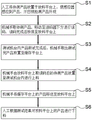
FIG. 13 illustrates a loading/unloading method for a testing machine according to a second embodiment of the present invention;
fig. 14 is a method for loading and unloading a test machine according to a third embodiment of the present invention.
Reference numerals: 1-a rack, 2-a carrying mechanism, 20-a mounting plate, 21-a first suction cup, 22-a second suction cup, 23-a driving part, 24-a first suction nozzle, 25-a sliding block, 3 a-an empty tray feeding frame, 3 b-a full tray feeding frame, 3 c-a qualified product discharging frame, 3 d-a defective product discharging frame, 31-a top tray clamping mechanism, 310-a support frame, 311-a clamping block, 3110-a telescopic part, 312-a positioning block, 313-an adjusting mechanism, 3131-a mounting table, 3132-a sliding rail, 3133-a strip groove, 3134-a bolt mounting hole, 3135-a scale, 32-a lifting saddle, 321-an X-direction moving mechanism, 322-Z-direction moving mechanism, 33-a carrying table, 331-a handle, 332-a limiting block, 4-a discharging platform, 41-a positioning boss, 42-a sensor, 43-a second suction nozzle, 44-a notch, 5-a buffer platform, 51-a gas separating valve, 52-a first gas groove, 521-a first gas hole, 531-a second gas code reader, 7-a second gas code reader and 6-a picture collecting device.
Detailed Description
The foregoing and other technical and scientific aspects, features and advantages of the present invention will be apparent from the following detailed description of a preferred embodiment, which is to be read in connection with the accompanying drawings. Directional terms as referred to in the following examples, for example: up, down, left, right, front or rear, etc., are referred to only in the direction of the attached drawings. Accordingly, the directional terminology is used for purposes of illustration and is in no way limiting.
The first embodiment is as follows:
the loading and unloading device for the test machine of the embodiment shown in fig. 1 and fig. 2 comprises a carrying mechanism 2, four tray frames 3a,3b,3c and 3d, a discharging platform 4 for placing a first product and a buffer platform 5 for placing a tested product, wherein the four tray frames 3a,3b,3c and 3d are respectively an empty tray loading frame 3a for placing stacked empty trays, a full tray loading frame 3b for placing stacked full trays, a qualified product discharging frame 3c and a defective product discharging frame 3d, trays on the tray frames are used for placing a second product, and the second product is different from the first product in size; the carrying mechanism 2 is located on the front side of the testing machine, the emptying platform 4 is located on the front side of the carrying mechanism 2, the buffer storage platform 5 is located between the carrying mechanism 2 and the testing machine, the empty tray feeding rack 3a and the full tray feeding rack 3b are located on the left side of the carrying mechanism 2, the qualified product discharging rack 3c and the defective product discharging rack 3d are located on the right side of the carrying mechanism 2, and the carrying mechanism 2 is used for mutual transfer of the first product among the emptying platform 4, the buffer storage platform 5 and the testing machine and for mutual transfer of the second product and the empty tray among the four tray racks 3a,3b,3c and 3d, the buffer storage platform 5 and the testing machine. In other embodiments, the number of tray racks can be increased as a supplement, where space permits.
In the present embodiment, the conveyance mechanism 2 is a robot, but in another embodiment, it may be an integrated device such as a linear motion mechanism, a turntable, or a suction cup. Because the full-plate material feeding frame 3b is used for taking materials and the qualified product discharging frame 3c is used for discharging materials, the full-plate material feeding frame 3b and the qualified product discharging frame 3c are close to the position of the test machine table in order to further save the movement stroke of the carrying mechanism 2. And a code reader 7 for reading product information is arranged on one side of the cache platform 5 close to the test machine.
As shown in fig. 3, arcs indicate the range of the track of the carrying mechanism 2, and arrows indicate the taking and discharging directions of the tray frames 3a,3b,3c, 3d.
Fig. 4 shows the state diagram of the tray frames 3a,3b,3c,3d and the emptying platform 4, the buffer storage platform 5 when arranging in a straight line in the one side of the carrying mechanism 2, it can be seen that the wasted space of the equipment is great under this arrangement, the space utilization rate is low, the arm of the carrying mechanism 2 needs to be lengthened, the track is longer, the time required by loading and unloading can be correspondingly increased, compared with the above, the present embodiment has the advantages that the space size of the equipment can be small, the time for loading and unloading can be saved, and the work efficiency can be improved.
Fig. 5 shows a state diagram of the tray frames 3a,3b,3c,3d, the emptying platform 4, the buffer storage platform 5 are circumferentially and evenly distributed around the carrying mechanism 2, it can be seen that the area occupied by the spreading arm and the equipment of the carrying mechanism 2 need to be increased a little under the arrangement, meanwhile, the directions of taking and placing the tray frames 3a,3b,3c,3d are all different, the operator is inconvenient to take and place the tray frames, compared with the above, the present embodiment has the advantages that the manual work is convenient for loading and unloading of stacked trays, the labor intensity is reduced, the track of loading and unloading of the carrying mechanism 2 is small, and the work efficiency is improved.
In this embodiment, the test board is used for the test of circuit board, and in order to prevent external disturbance, frame 1 seals with black plastic-aluminum board, locates the emergency exit of being convenient for go up unloading in frame 1's both sides and front side.
The small-size products, namely the second products, are generally transported through a tray, during testing, the carrying mechanism 2 takes the full-tray feeding frame 3b to take the full-tray feeding frame to the testing machine, the full-tray feeding frame is temporarily placed on the cache platform 5 after detection is completed, the carrying mechanism 2 carries out feeding once again, the standby time of the testing machine is shortened, then the products on the cache platform 5 are fed to the qualified product discharging frame 3c or the defective product discharging frame 3d according to the detection result, and when the qualified product discharging frame 3c or the defective product discharging frame 3d are filled with the products, the carrying mechanism 2 fills the empty tray on the empty-tray feeding frame 3a with the empty tray. After the top layer product test of the full-tray material feeding frame 3b is completed, the empty tray is supplemented to the qualified product discharging frame 3c or the defective product discharging frame 3d according to the requirement, or is temporarily placed on the empty-tray material feeding frame 3 a.
For large-size products, namely first products, generally, the products are manually fed, during testing, the products are manually placed on the material placing platform 4, the conveying mechanism 2 takes the materials from the material placing platform 4 to the testing machine, the products are temporarily placed on the cache platform 5 after the detection is finished, the conveying mechanism 2 firstly feeds the products to be tested on the material placing platform 4, then the products on the cache platform 5 are fed onto the material placing platform 4, and personnel feed the products to the designated positions according to the detection results.
Transport mechanism 2 need accomplish the transportation of jumbo size product, small-size product, tray, in order to guarantee to be applicable to the firm absorption of not unidimensional object, combine fig. 6 and 7 to show, be equipped with parallel first sucking disc 21 and second sucking disc 22 on transport mechanism 2, all install first suction nozzle 24 on first sucking disc 21 and the second sucking disc 22, first sucking disc 21 middle part is equipped with the fretwork district, and second sucking disc 22 is connected with driving piece 23 to shuttle around under the effect of driving piece 23 in the fretwork district. In this embodiment, the driving member 23 is a cylinder, and in other embodiments, it may be another linear motion mechanism or a telescopic mechanism. The first suction nozzle 24 is respectively arranged at the corner parts of the first suction cup 21 and the second suction cup 22, when a large-size product is sucked, the first suction cup 21 is used, the air cylinder drives the second suction cup 22 to be positioned above the first suction cup 21, when a small-size product is sucked, the air cylinder drives the second suction cup 22 to move downwards to penetrate through the through hole and be positioned below the first suction cup 21, and when the tray is sucked, the first suction cup 21 or the second suction cup 22 is selected to be used according to the size of the tray.
In the present embodiment, the four corners of the first suction cup 21 are provided with the first suction nozzles 24, and since the second suction cup 22 is small in size, the first suction nozzles 24 are provided only at two corners, and in other embodiments, may be provided as needed according to the size of the suction object.
As shown in fig. 7, the first suction cup 21 and the second suction cup 22 are both provided with a sliding groove, the first suction nozzle 24 is installed on the sliding block 25, the sliding block 25 is connected in the sliding groove in a sliding manner, the installation position of the first suction nozzle 24 is adjusted before testing according to the specific size of a product in actual production, the suction firmness is further ensured, and a graduated scale is arranged at the edge of the sliding groove along the sliding direction of the sliding block 25, so that the adjustment distance can be visually observed conveniently.
In order to realize the automatic loading and unloading of small-size products, as shown in fig. 8, the tray rack includes a top tray clamping mechanism 31, a lifting tray table 32 and a carrier table 33 for placing the stacked trays, which are sequentially arranged from top to bottom, the carrier table 33 is installed on the rack 1, the lifting tray table 32 is used for supporting the stacked trays from the bottom of the bottommost tray and driving the stacked trays to ascend, so that the top tray reaches the height of the top tray clamping mechanism 31, and the top tray clamping mechanism 31 is used for clamping and fixing the top tray.
Specifically, the carrier 33 is of a drawer type structure and is provided with a handle 331 for pushing and pulling, a limiting block 332 is arranged on the upper surface of the carrier 33, the stacking tray is convenient to place at a fixed position, and a sensor is arranged at the other end of the limiting block 332. The lifting saddle 32 includes two opposite clamping members, which move toward or away from each other under the driving of the X-direction moving mechanism 321, and move up and down under the driving of the Z-direction moving mechanism 322. The top tray clamping mechanism 31 includes a bracket 310 and a clamping block 311 movably connected to the bracket 310, wherein the clamping block 311 moves toward or away from the top tray under the driving of an expansion member 3110. At least one side of the clamping blocks 311 on one group of adjacent sides of the bracket 310 is provided with a leaning block 312, in this embodiment, two sides, and the clamping blocks 311 on the other group of adjacent sides of the bracket 310 are provided with an adjusting mechanism 313 for adjusting the initial installation position. The leaning block 312 may have a square structure or a cylindrical structure, and in this embodiment, two adjacent sides respectively use the square structure and the cylindrical structure.
As shown in fig. 9, the adjusting mechanism 313 includes a sliding rail 3132 mounted on the support 310, a mounting block 3131 moving along the sliding rail 3132, and a bolt (not shown) for fixing the mounting position of the mounting block 3131, and a telescopic element 3130, which is an air cylinder in this embodiment, is mounted on the mounting block 3131 and is located below the support 310. A strip groove 3133 is formed in the mounting plate 310, and a bolt mounting hole 3134 is formed at a position corresponding to the mounting plate 3131. A graduated scale 3135 is arranged on one side of the sliding rail 3132, and the graduated scale 3135 is marked according to the adjusted product size, so that the adjustment is convenient and direct according to the product size, and calculation is not needed. During adjustment, the mounting base 3131 may be moved along the slide rail 3132 by loosening the screw.
During operation, to the full dish work or material rest 3b of going into, pulling handle 331 and deviating from microscope carrier 33, will pile up the tray and place on microscope carrier 33 to fix a position through stopper 332, make the inductor can sense and pile up the tray. When the product detection on the lifting tray table 32 is completed, the conveying mechanism 2 takes out the last empty tray, the lifting tray table 32 descends, the stacked trays on the carrying table 33 are lifted and ascend, the top tray reaches the height of the top tray clamping mechanism 31 and contacts with the leaning block 312, the clamping block 311 is driven by the telescopic piece 3110 to clamp the top tray, the material supplement of full trays is completed, after the product detection in the top tray is completed, the clamping block 311 is released, the conveying mechanism 2 takes out the empty tray, the lifting tray table 32 ascends by the height of one tray, and the clamping block 311 clamps again.
The working mode of the empty tray feeding frame 3a is the same as that of the full tray feeding frame 3 b.
For the qualified product discharging frame 3c, the qualified products are placed on the top layer tray by the carrying mechanism 2, after the top layer tray is filled, the lifting support table 32 descends by the height of one tray, the carrying mechanism 2 takes the empty tray from the empty tray feeding frame 3a to supplement the qualified product discharging frame 3c, after the set stacking layer number is reached, the lifting support table 32 descends to place the stacked tray on the carrying platform 33 and then ascends, and the carrying mechanism 2 takes the empty tray from the full tray feeding frame 3b to supplement the empty tray on the top tray clamping mechanism 31.
The defective product discharging frame 3d and the qualified product discharging frame 3c have the same working mode.
As shown in fig. 2, an image acquisition device 6 is arranged above the full-plate material feeding frame 3b and used for photographing products in the full plate, acquiring position information of the products to be detected and detecting the appearance of the products. In the present embodiment, in order to save space, the image capturing device 6 is mounted on the rack 1 at the top of the full-tray loading frame 3b, and in other embodiments, may be mounted at other positions. Image acquisition device 6 mainly detects whether there is defect such as crackle, fragment, unfilled corner in the product, and transport mechanism 2 carries out position compensation according to the positional information of feedback in addition, makes transport mechanism 2 can put into the product and confirms the position in the test board, the accurate and high efficiency of being convenient for detect.
For large-size products, as shown in fig. 10, the placing platform 4 is provided with a positioning boss 41 for improving the precision of the placing position of the product and an inductor 42 for detecting whether the product is placed in place. The leaning boss 41 is L-shaped, positioning is carried out by taking one angle of a product as a reference, and the sensors 42 are respectively arranged at the tail ends of two sides of the leaning boss 41, so that the product is prevented from being placed partially, and the position accuracy of the conveying mechanism 2 for feeding the product to the testing machine is guaranteed. And a second suction nozzle 43 is arranged on the discharging platform 4 and used for adsorbing and fixing products to prevent accidental collision and damage. According to different sizes of large-size products, an adsorption area formed by different second suction nozzles 43 is arranged on the discharging platform 4, and the air distribution valve is arranged to control the second suction nozzles 43 in the adsorption area to generate negative pressure according to requirements. A notch 44 is also arranged on the material placing disc platform 4, so that the product can be conveniently taken down manually.
As the large-size products are manually loaded and unloaded, whether the large-size products have appearance defects such as cracks, fragments, unfilled corners and the like is manually and visually detected. In other embodiments, an image acquisition device may be added as needed to complete the appearance detection.
As shown in fig. 11 and 12, the buffer platform 5 is also provided with different sizes of adsorption zones, each adsorption zone is formed by consecutive end-to-end air grooves, and air holes for connecting air pipes are arranged in the air grooves. Specifically, the large adsorption area is formed by a first air groove 52, and a first air hole 521 connected with an air pipe is arranged in the first air groove 52; the small adsorption area is composed of a second air groove 53, and a second air hole 531 connected with an air pipe is arranged in the second air groove 53; the air separating valve 51 controls the first air groove 52 or the second air groove 53 to generate negative pressure according to the size of the product to be placed. In order to save space, the second air channel 53 is located inside the enclosed area of the first air channel 52 in this embodiment.
Example two:
as shown in fig. 13, this embodiment provides a method for loading and unloading a product in a tray by using the loading and unloading apparatus for a test machine, which includes the following steps:
s1, an image acquisition device 6 shoots and positions a product to be detected in a full tray at the uppermost layer, detects the appearance of the product and judges whether the product has defects of cracks, fragments, unfilled corners and the like, and because the defects are rare, when the defects are judged to exist, equipment alarms, personnel manually removes the defects and does not continuously feed the material;
s2, the carrying mechanism 2 takes a product to be detected according to the product position information, moves to the position below the code reader 7 to read the code, and after the code reading is finished, the product is placed back to the original position in the uppermost full tray, the image code for marking the product information is positioned at one corner of the product, and if the image code is not read during the code reading, the carrying mechanism 2 drives the product to rotate 180 degrees to ensure that the product information is read;
s3, after the product in the testing machine is tested, the conveying mechanism 2 takes out the tested product and places the tested product on the cache platform 5, and the cache platform 5 is located between the conveying mechanism 2 and the testing machine, so that the time spent in the step is short;
s4, the carrying mechanism 2 takes out the products which are read from the full tray on the uppermost layer and places the products into a testing machine for loading, and because the carrying mechanism 2 compensates according to the position information when taking out the products and reading the codes, when the products are placed back to the original position, the placing angle of the products is adjusted to the placing angle required by the test, so that the position information does not need to be obtained by taking pictures before the step is carried out;
and S5, the carrying mechanism 2 discharges the products on the buffer platform 5 into the trays on the tray rack of the qualified products or the defective products according to the detection result.
In the method, the conveying mechanism 2 temporarily places the tested product on the buffer storage platform 5, and immediately loads the next product to be tested, so that the standby time of the testing machine is saved; when the test machine is used for testing, the carrying mechanism 2 is used for reading the code of the next product to be tested and blanking the product after the previous test, so that the test time is reasonably utilized, the test frequency is improved, the test pace is accelerated, and the test efficiency is improved.
Example three:
as shown in fig. 14, the present embodiment provides a method for loading and unloading a large-sized product of a single chip product machine by using the loading and unloading apparatus for a testing machine, including the following steps:
s1, manually placing a product to be tested on a discharging platform 4, enabling an inductor 42 to induce the product, visually detecting the appearance of the product, judging whether the product has defects such as cracks, fragments, unfilled corners and the like, and automatically removing the product by personnel without continuously feeding when the defects exist;
s2, the carrying mechanism 2 takes a product to be detected, moves to the position below the code reader 7 to read codes, and puts the product back to the discharging platform 4 after the code reading is finished; similarly, because the placing direction is uncertain, if the figure code is not read during code reading, the carrying mechanism 2 drives the product to rotate 180 degrees, and the product information is ensured to be read;
s3, after the product in the testing machine is tested, the carrying mechanism 2 takes out the tested product and places the tested product on the cache platform 5;
s4, the carrying mechanism 2 takes the product to be tested after code reading from the material placing platform 4 and places the product into a testing machine for feeding; because the placing platform 4 is provided with the leaning boss 41 and the inductor 42, the placing precision of the product is high, and meanwhile, a test machine platform allows a small amount of position errors for the test of a large-size product, so that the position alignment is not needed;
s5, the conveying mechanism 2 conveys the products on the cache platform 5 to the discharging platform 4;
and S6, manually blanking the product on the discharging platform 4 according to the test result.
In the method, the appearance of the product is manually and visually detected by utilizing the advantages of manual feeding and discharging, so that the equipment cost is saved, and the equipment volume is reduced; meanwhile, the method has the advantages of reasonably utilizing the testing time, improving the testing frequency and accelerating the testing pace which are the same as those of the embodiment, thereby improving the testing efficiency.
The loading and unloading device and the loading and unloading method for the test machine provided by the invention are described in detail, the structure, the method and the working principle of the invention are explained only by applying specific examples, and the description of the embodiments is only used for helping to understand the method and the core idea of the invention. It should be noted that, for those skilled in the art, it is possible to make various improvements and modifications to the present invention without departing from the principle of the present invention, and those improvements and modifications also fall within the scope of the claims of the present invention.