CN115289727A - Dynamic joint energy-saving dehumidification system - Google Patents
Dynamic joint energy-saving dehumidification system Download PDFInfo
- Publication number
- CN115289727A CN115289727A CN202210890210.7A CN202210890210A CN115289727A CN 115289727 A CN115289727 A CN 115289727A CN 202210890210 A CN202210890210 A CN 202210890210A CN 115289727 A CN115289727 A CN 115289727A
- Authority
- CN
- China
- Prior art keywords
- sleeve
- pipe
- liquid
- recovery device
- heat recovery
- Prior art date
- Legal status (The legal status is an assumption and is not a legal conclusion. Google has not performed a legal analysis and makes no representation as to the accuracy of the status listed.)
- Granted
Links
Images




Classifications
-
- F—MECHANICAL ENGINEERING; LIGHTING; HEATING; WEAPONS; BLASTING
- F25—REFRIGERATION OR COOLING; COMBINED HEATING AND REFRIGERATION SYSTEMS; HEAT PUMP SYSTEMS; MANUFACTURE OR STORAGE OF ICE; LIQUEFACTION SOLIDIFICATION OF GASES
- F25B—REFRIGERATION MACHINES, PLANTS OR SYSTEMS; COMBINED HEATING AND REFRIGERATION SYSTEMS; HEAT PUMP SYSTEMS
- F25B43/00—Arrangements for separating or purifying gases or liquids; Arrangements for vaporising the residuum of liquid refrigerant, e.g. by heat
Landscapes
- Engineering & Computer Science (AREA)
- Chemical & Material Sciences (AREA)
- Analytical Chemistry (AREA)
- Power Engineering (AREA)
- Physics & Mathematics (AREA)
- Mechanical Engineering (AREA)
- Thermal Sciences (AREA)
- General Engineering & Computer Science (AREA)
- Drying Of Gases (AREA)
Abstract
Description
技术领域technical field
本发明涉及节能除湿技术领域,尤其涉及动态联合节能除湿系统。The invention relates to the technical field of energy saving and dehumidification, in particular to a dynamic combined energy saving and dehumidification system.
背景技术Background technique
目前在潜热热回收器的回收热能的时候会出现虽然气流流经潜热热回收器,温度降低、其中水分被冷凝,潜热被利用,但是这部分的水汽依旧暂留在潜热热回收器中,影响后续的降温;其次潜热热回收器中的液态制冷剂吸热气化由于无法及时的排出,会与周围冷的制冷剂混合重新变为液态,则无法被压缩机进行压缩操作。At present, when the latent heat recovery device recovers heat energy, although the air flow flows through the latent heat recovery device, the temperature drops, the moisture in it is condensed, and the latent heat is used, but this part of the water vapor still stays in the latent heat recovery device temporarily, affecting Subsequent cooling; secondly, the liquid refrigerant in the latent heat recovery device absorbs heat and vaporizes because it cannot be discharged in time, and it will mix with the surrounding cold refrigerant and become liquid again, so it cannot be compressed by the compressor.
为此,我们设计了动态联合节能除湿系统。To this end, we have designed a dynamic joint energy-saving dehumidification system.
发明内容Contents of the invention
本发明的目的是为了解决气流流经潜热热回收器,温度降低、其中水分被冷凝,潜热被利用,但是这部分的水汽依旧暂留在潜热热回收器中,影响后续的降温的问题,而提出的动态联合节能除湿系统。The purpose of the present invention is to solve the problem that the airflow flows through the latent heat recovery device, the temperature drops, the moisture in it is condensed, and the latent heat is utilized, but this part of the water vapor still stays in the latent heat recovery device, affecting the subsequent cooling problem, and Proposed dynamic joint energy-saving dehumidification system.
为了实现上述目的,本发明采用了如下技术方案:In order to achieve the above object, the present invention adopts the following technical solutions:
动态联合节能除湿系统,包括节能除湿装置,以及位于节能除湿装置内的潜热热回收器,所述潜热热回收器包括热回收器箱体以及设置在热回收器箱体内的弯折管,所述弯折管上套设有气液分离机构和冷凝液回收装置,所述气液分离机构通过贯穿弯折管的下压杆与冷凝液回收装置相连,所述热回收器箱体上分别插设有第四管口、与弯折管首尾连通的第一管口和第二管口,以及与气液分离机构连通的第三管口,所述冷凝液回收装置通过胶管与外界连通,所述热回收器箱体内充有液态制冷剂。The dynamic joint energy-saving dehumidification system includes an energy-saving dehumidification device and a latent heat recovery device located in the energy-saving dehumidification device. A gas-liquid separation mechanism and a condensate recovery device are set on the bent tube. The gas-liquid separation mechanism is connected to the condensate recovery device through a lower pressure rod passing through the bent tube. The heat recovery box is respectively inserted There is a fourth nozzle, a first nozzle and a second nozzle connected to the end of the bending pipe, and a third nozzle connected to the gas-liquid separation mechanism. The condensate recovery device communicates with the outside world through the rubber hose. The heat recovery tank is filled with liquid refrigerant.
优选地,所述气液分离机构包括套设在弯折管顶部的包覆套,以及插设在弯折管侧壁的多个导热棒,所述包覆套包括第一套管和第二套管,所述第一套管和第二套管之间设有呈T形的进液管,所述进液管内设有阻液机构,所述第一套管和第二套管顶部均设有与第三管口连通的出气管。Preferably, the gas-liquid separation mechanism includes a cladding sleeve set on the top of the bent tube, and a plurality of heat conducting rods inserted on the side wall of the bent tube, and the cladding sleeve includes a first sleeve and a second sleeve. casing, a T-shaped liquid inlet pipe is provided between the first casing and the second casing, and a liquid blocking mechanism is arranged in the liquid inlet pipe, and the tops of the first casing and the second casing are both An air outlet pipe communicating with the third nozzle is provided.
优选地,所述冷凝液回收装置包括开设在弯折管内壁底部的活动槽、在活动槽内对称滑动的两个挤推板,以及设置在相邻两个挤推板之间的拉伸密封带,两个所述挤推板相背一侧且位于活动槽内设有用于吸收冷凝水的吸水海绵,所述活动槽两侧均设有排水机构,所述活动槽底部开设有滑动孔,所述下压杆贯穿拉伸密封带和活动槽,所述下压杆通过支撑杆和轴台与下压杆两侧的挤推板底部相连。Preferably, the condensate recovery device includes an active groove at the bottom of the inner wall of the bent tube, two pushing plates sliding symmetrically in the moving groove, and a stretch seal arranged between two adjacent pushing plates belt, the opposite side of the two pushing plates and the water-absorbing sponge for absorbing condensed water are arranged in the movable groove, the drainage mechanism is arranged on both sides of the movable groove, and a sliding hole is opened at the bottom of the movable groove, The lower pressing rod runs through the stretch sealing band and the movable groove, and the lower pressing rod is connected with the bottoms of the pressing plates on both sides of the lower pressing rod through the supporting rod and the pillow block.
优选地,所述进液管位于第一套管和第二套管之间的底部,且用于连通热回收器箱体与第一套管和第二套管之间空间。Preferably, the liquid inlet pipe is located at the bottom between the first casing and the second casing, and is used to communicate with the heat recovery tank and the space between the first casing and the second casing.
优选地,所述阻液机构包括在进液管内上下滑动的升降块、用于对升降块限位的限位环,以及开设在进液管侧壁的侧管,所述进液管内固定有第一支架,且升降块与第一支架之间连接有第一复位弹簧。Preferably, the liquid blocking mechanism includes a lifting block that slides up and down in the liquid inlet pipe, a limit ring for limiting the lifting block, and a side pipe set on the side wall of the liquid inlet pipe, and the liquid inlet pipe is fixed with the first bracket, and a first return spring is connected between the lifting block and the first bracket.
优选地,所述出气管下方设有堵住出气管的堵塞块,且堵塞块顶部开设有第二倾斜倒角,所述出气管底部开设有与第二倾斜倒角相适配的第一倾斜倒角,所述出气管内设有第二支架,且第二支架与堵塞块之间连接有第二复位弹簧。Preferably, a blocking block is provided below the air outlet pipe to block the air outlet pipe, and the top of the blocking block is provided with a second inclined chamfer, and the bottom of the air outlet pipe is provided with a first inclined chamfer matching the second inclined chamfer. chamfering, a second bracket is arranged in the outlet pipe, and a second return spring is connected between the second bracket and the blocking block.
优选地,所述排水机构包括下水管、设置在下水管上方的轻质小球,以及开设在下水管顶部且与轻质小球相适配的球槽,所述下水管内设有第三支架,且第三支架与轻质小球之间通过第三复位弹簧相连。Preferably, the drainage mechanism includes a downpipe, a light ball arranged above the downpipe, and a ball groove set on the top of the downpipe and adapted to the light ball, and a third bracket is arranged inside the downpipe, And the third bracket is connected with the light ball through the third return spring.
本发明的有益效果为:The beneficial effects of the present invention are:
1、本发明采用堵塞块材质密度小于液态制冷剂,那样堵塞块便会浮在液态制冷剂上,当第一套管和第二套管上存在气态制冷剂时,此时堵塞块便会下坠,当第一套管和第二套管中气态制冷剂排出时,此时的出气管便会重新关闭,这样设置可以避免液态制冷剂吸热气化由于无法及时的排出,会与周围冷的制冷剂混合重新变为液态,则无法被压缩机进行压缩操作。1. In the present invention, the material density of the blocking block is lower than that of the liquid refrigerant, so that the blocking block will float on the liquid refrigerant. When there is gaseous refrigerant on the first casing and the second casing, the blocking block will fall down at this time , when the gaseous refrigerant in the first casing and the second casing is discharged, the outlet pipe will be closed again at this time. This setting can prevent the liquid refrigerant from absorbing heat and vaporizing because it cannot be discharged in time, and it will be in contact with the surrounding cold The refrigerant mixture becomes liquid again and cannot be compressed by the compressor.
2、本发明采用下压杆通过支撑杆和轴台与下压杆两侧的挤推板底部相连,那样在下压着下压杆的时候便可以将两侧的挤推板撑开并完成对含水吸水海绵的挤压,需要说明的是,在含水吸水海绵被挤压时轻质小球受到浮力便会飘起,进而打开了原本闭合的下水管,进而可以起到排水效果,解决了水分被冷凝,潜热被利用后水汽依旧暂留在潜热热回收器中,影响后续的降温的问题。2. The present invention adopts the lower pressing rod to be connected with the bottom of the push plate on both sides of the lower pressing rod through the support rod and the pillow block, so that when the lower pressing rod is pressed down, the pushing plates on both sides can be stretched and the alignment can be completed. Extrusion of the water-absorbing sponge. It should be noted that when the water-absorbing sponge is squeezed, the light ball will float up due to the buoyancy, and then open the originally closed downpipe, which can have a drainage effect and solve the problem of moisture. After being condensed and the latent heat is utilized, the water vapor still stays in the latent heat recovery device, affecting the subsequent cooling problem.
附图说明Description of drawings
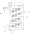
图1为本发明提出的动态联合节能除湿系统中热回收器箱体的结构示意图;Fig. 1 is the structural representation of the heat recovery box body in the dynamic joint energy-saving dehumidification system proposed by the present invention;
图2为本发明提出的热回收器箱体中包覆套的结构示意图;Fig. 2 is the structural schematic diagram of the cladding sleeve in the heat recovery box body proposed by the present invention;
图3为本发明提出的热回收器箱体中包覆套的主视图;Fig. 3 is the front view of the cladding sleeve in the heat recovery box body proposed by the present invention;
图4为本发明提出的热回收器箱体中进液管的结构示意图;Fig. 4 is the schematic structural view of the liquid inlet pipe in the heat recovery box body proposed by the present invention;
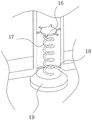
图5为本发明提出的热回收器箱体中出气管的结构示意图;Fig. 5 is the structural representation of the air outlet pipe in the heat recovery box body proposed by the present invention;
图6为本发明提出的热回收器箱体中挤液机构的结构示意图;Fig. 6 is a structural schematic diagram of the liquid squeezing mechanism in the heat recovery box body proposed by the present invention;
图7为本发明提出的热回收器箱体中下水管的结构示意图。Fig. 7 is a structural schematic diagram of the downwater pipe in the heat recovery box body proposed by the present invention.
图中:1热回收器箱体、2弯折管、3第一管口、4第二管口、5 第三管口、6第四管口、7包覆套、71第一套管、72第二套管、8出气管、9进液管、10下压杆、11升降块、12限位环、13第一复位弹簧、14侧管、15第一支架、16第二支架、17第二复位弹簧、18第一倾斜倒角、19堵塞块、20导热棒、21挤推板、22活动槽、23支撑杆、24轴台、25滑动孔、26拉伸密封带、27吸水海绵、28下水管、29第三支架、30第三复位弹簧、31球槽、32轻质小球。In the figure: 1 heat recovery box, 2 bent tube, 3 first nozzle, 4 second nozzle, 5 third nozzle, 6 fourth nozzle, 7 cladding sleeve, 71 first casing, 72 second casing, 8 air outlet pipe, 9 liquid inlet pipe, 10 lower pressure rod, 11 lifting block, 12 limit ring, 13 first return spring, 14 side pipe, 15 first bracket, 16 second bracket, 17 Second return spring, 18 first inclined chamfer, 19 blockage block, 20 heat conduction rod, 21 pushing plate, 22 movable groove, 23 support rod, 24 shaft platform, 25 sliding hole, 26 stretch sealing tape, 27 water-absorbing sponge , 28 water pipes, 29 third supports, 30 third return springs, 31 ball grooves, 32 light weight balls.
具体实施方式Detailed ways
参照图1-7,动态联合节能除湿系统,包括节能除湿装置,以及位于节能除湿装置内的潜热热回收器,参照图1示,潜热热回收器包括热回收器箱体1以及设置在热回收器箱体1内的弯折管2,参照图 2示,弯折管2上套设有气液分离机构和冷凝液回收装置,气液分离机构通过贯穿弯折管2的下压杆10与冷凝液回收装置相连,其中下压杆10一端与升降块11相连,那样随着升降块11的升降便可以带动下压杆10一同升降,并触发下方的冷凝液回收装置启动。Referring to Figures 1-7, the dynamic joint energy-saving dehumidification system includes an energy-saving dehumidification device and a latent heat recovery device located in the energy-saving dehumidification device. Referring to Figure 1, the latent heat recovery device includes a heat recovery box 1 and a heat recovery The
热回收器箱体1上分别插设有第四管口6、与弯折管2首尾连通的第一管口3和第二管口4,以及与气液分离机构连通的第三管口5,冷凝液回收装置通过胶管与外界连通,热回收器箱体1内充有液态制冷剂,那样变成气态的制冷剂会从第三管口5出去,并被压缩机20压缩。The heat recovery tank 1 is respectively inserted with a
气液分离机构包括套设在弯折管2顶部的包覆套7,以及插设在弯折管2侧壁的多个导热棒20,包覆套7包括第一套管71和第二套管72,进液管9位于第一套管71和第二套管72之间的底部,且用于连通热回收器箱体1与第一套管71和第二套管72之间空间,参照图3-4示,这样设置能够确保在通入弯折管2内的热气经过导热棒 20时,热量被导热棒20传导到第一套管71和第二套管72内,而原本位于第一套管71和第二套管72内的液态制冷剂被加热到气态,那样气态的制冷剂会位于第一套管71和第二套管72上方空间,由于此时第一套管71和第二套管72压力变大,就会不断的顶起位于进液管 9内的升降块11。The gas-liquid separation mechanism includes a
第一套管71和第二套管72之间设有呈T形的进液管9,进液管 9内设有阻液机构,参照图5示,阻液机构包括在进液管9内上下滑动的升降块11、用于对升降块11限位的限位环12,以及开设在进液管9侧壁的侧管14,进液管9内固定有第一支架15,且升降块11与第一支架15之间连接有第一复位弹簧13,在进液管9内的升降块11 被顶起的时候,升降块11不断的被压缩,并且当升降块11到达侧管 14进液口上方时,原本堵住的侧管14便会开放,并对第一套管71 和第二套管72开始填充液态制冷剂,在第一复位弹簧13的作用下升降块11会重新下降并堵住侧管14,然后在升降块11不断往复的上下运动过程中便会带着下方的下压杆10一同升降。A T-shaped
参照图6示,第一套管71和第二套管72顶部均设有与第三管口 5连通的出气管8,出气管8下方设有堵住出气管8的堵塞块19,且堵塞块19顶部开设有第二倾斜倒角,出气管8底部开设有与第二倾斜倒角相适配的第一倾斜倒角18,出气管8内设有第二支架16,且第二支架16与堵塞块19之间连接有第二复位弹簧17,需要说明的是,堵塞块19材质密度小于液态制冷剂,那样堵塞块19便会浮在液态制冷剂上,当第一套管71和第二套管72上存在气态制冷剂时,此时堵塞块19便会下坠,并打开原本被堵住的第一倾斜倒角18,让气态的制冷剂从上方排出,而从侧管14中进入第一套管71和第二套管 72内的液态制冷剂便可以将存在第一套管71和第二套管72上存在气态制冷剂挤压出第一套管71和第二套管72,当第一套管71和第二套管72中气态制冷剂排出时,此时的出气管8便会重新关闭,这样设置可以避免液态制冷剂吸热气化由于无法及时的排出,会与周围冷的制冷剂混合重新变为液态,则无法被压缩机进行压缩操作。Referring to Fig. 6, the
冷凝液回收装置包括开设在弯折管2内壁底部的活动槽22、在活动槽22内对称滑动的两个挤推板21,以及设置在相邻两个挤推板 21之间的拉伸密封带26,这样可以有效的避免在两个挤推板21相背运动时露出滑动孔25,让位于弯折管2内的热气泄露,两个挤推板21相背一侧且位于活动槽22内设有用于吸收冷凝水的吸水海绵27,吸水海绵27的设置能够有效的避免带有水汽的热气水分被冷凝,活动槽22两侧均设有排水机构,参照图7示,排水机构包括下水管28、设置在下水管28上方的轻质小球32,以及开设在下水管28顶部且与轻质小球32相适配的球槽31,下水管28内设有第三支架29,且第三支架29与轻质小球32之间通过第三复位弹簧30相连,活动槽 22底部开设有滑动孔25,下压杆10贯穿拉伸密封带26和活动槽22,下压杆10通过支撑杆23和轴台24与下压杆10两侧的挤推板21底部相连,那样在下压着下压杆10的时候便可以将两侧的挤推板21撑开并完成对含水吸水海绵27的挤压,需要说明的是,在含水吸水海绵27被挤压时轻质小球32受到浮力便会飘起,进而打开了原本闭合的下水管28,进而可以起到排水效果,解决了水分被冷凝,潜热被利用后水汽依旧暂留在潜热热回收器中,影响后续的降温的问题。The condensate recovery device includes an
本发明的工作原理如下:节能除湿装置工作时,带有水汽的热气通过热回收器箱体1内的弯折管2,使得弯折管2内热气热量传递到第一套管71和第二套管72内,而原本位于第一套管71和第二套管 72内的液态制冷剂被加热到气态,气态的制冷剂会从出气管8排出,而这也会带着下压杆10不断地升降,进而可以驱动挤推板21挤压吸满水的吸水海绵27,并将水从下水管28排出。The working principle of the present invention is as follows: when the energy-saving dehumidification device is working, the hot gas with water vapor passes through the
以上所述,仅为本发明较佳的具体实施方式,但本发明的保护范围并不局限于此,任何熟悉本技术领域的技术人员在本发明揭露的技术范围内,根据本发明的技术方案及其发明构思加以等同替换或改变,都应涵盖在本发明的保护范围之内。The above is only a preferred embodiment of the present invention, but the scope of protection of the present invention is not limited thereto, any person familiar with the technical field within the technical scope disclosed in the present invention, according to the technical solution of the present invention Any equivalent replacement or change of the inventive concepts thereof shall fall within the protection scope of the present invention.
Claims (7)
Priority Applications (1)
| Application Number | Priority Date | Filing Date | Title |
|---|---|---|---|
| CN202210890210.7A CN115289727B (en) | 2022-07-27 | 2022-07-27 | Dynamic combined energy-saving dehumidification system |
Applications Claiming Priority (1)
| Application Number | Priority Date | Filing Date | Title |
|---|---|---|---|
| CN202210890210.7A CN115289727B (en) | 2022-07-27 | 2022-07-27 | Dynamic combined energy-saving dehumidification system |
Publications (2)
| Publication Number | Publication Date |
|---|---|
| CN115289727A true CN115289727A (en) | 2022-11-04 |
| CN115289727B CN115289727B (en) | 2025-01-28 |
Family
ID=83824329
Family Applications (1)
| Application Number | Title | Priority Date | Filing Date |
|---|---|---|---|
| CN202210890210.7A Active CN115289727B (en) | 2022-07-27 | 2022-07-27 | Dynamic combined energy-saving dehumidification system |
Country Status (1)
| Country | Link |
|---|---|
| CN (1) | CN115289727B (en) |
Citations (6)
| Publication number | Priority date | Publication date | Assignee | Title |
|---|---|---|---|---|
| JPH11201577A (en) * | 1998-01-08 | 1999-07-30 | Rinnai Corp | Absorption air conditioner |
| CN2740972Y (en) * | 2004-02-29 | 2005-11-16 | 马强 | Air conditioner set |
| CN201355161Y (en) * | 2009-02-25 | 2009-12-02 | 浙江春晖智能控制股份有限公司 | High-efficiency gas-liquid separator |
| CN201666691U (en) * | 2010-04-15 | 2010-12-08 | 海信(山东)空调有限公司 | Cooling cycle system and air conditioner equipped with vapor-liquid separator |
| CN104121733A (en) * | 2014-08-07 | 2014-10-29 | 山东北辰机电设备股份有限公司 | Lithium bromide absorption type refrigerating cycle float-type air extractor |
| CN104136865A (en) * | 2012-02-23 | 2014-11-05 | 丰田自动车株式会社 | Cooling device, vehicle equipped with the cooling device, and method of controlling the cooling device |
-
2022
- 2022-07-27 CN CN202210890210.7A patent/CN115289727B/en active Active
Patent Citations (6)
| Publication number | Priority date | Publication date | Assignee | Title |
|---|---|---|---|---|
| JPH11201577A (en) * | 1998-01-08 | 1999-07-30 | Rinnai Corp | Absorption air conditioner |
| CN2740972Y (en) * | 2004-02-29 | 2005-11-16 | 马强 | Air conditioner set |
| CN201355161Y (en) * | 2009-02-25 | 2009-12-02 | 浙江春晖智能控制股份有限公司 | High-efficiency gas-liquid separator |
| CN201666691U (en) * | 2010-04-15 | 2010-12-08 | 海信(山东)空调有限公司 | Cooling cycle system and air conditioner equipped with vapor-liquid separator |
| CN104136865A (en) * | 2012-02-23 | 2014-11-05 | 丰田自动车株式会社 | Cooling device, vehicle equipped with the cooling device, and method of controlling the cooling device |
| CN104121733A (en) * | 2014-08-07 | 2014-10-29 | 山东北辰机电设备股份有限公司 | Lithium bromide absorption type refrigerating cycle float-type air extractor |
Also Published As
| Publication number | Publication date |
|---|---|
| CN115289727B (en) | 2025-01-28 |
Similar Documents
| Publication | Publication Date | Title |
|---|---|---|
| CN115970309B (en) | Multi-effect integrated falling film evaporator and application method thereof | |
| WO2020125008A1 (en) | Heat exchange structure for compressed air refrigerated dryer | |
| CN113566535A (en) | Raw material drying device for processing light building materials | |
| CN208765116U (en) | A kind of dehumidifier | |
| CN105240239A (en) | Solar double-piston pump | |
| CN110530042B (en) | Refrigerating unit waste heat grading hot water utilization system and method | |
| CN111795595A (en) | A cold pipe system | |
| CN111594934A (en) | Wireless mobile air conditioning unit with direct refrigerant contact type energy charging function | |
| CN120084160B (en) | Energy-saving heat exchanger | |
| CN201138106Y (en) | A liquid nitrogen heat exchange device for liquid nitrogen-assisted freeze-drying equipment | |
| CN115289727B (en) | Dynamic combined energy-saving dehumidification system | |
| CN206642381U (en) | Rotary Evaporators with circulating water refrigerating plant | |
| CN208475491U (en) | A kind of diaphragm type heat tube moisture device | |
| CN219347392U (en) | Portable air condensation system based on semiconductor refrigeration | |
| CN209295405U (en) | An air conditioner drain pipe that prevents water from flowing backwards | |
| CN217584694U (en) | Small-space efficient heat exchange device | |
| CN110398011A (en) | A kind of refrigeration system | |
| CN206001103U (en) | A kind of vacuum and low temperature clack box | |
| CN117469843A (en) | a heat pump system | |
| CN115888159A (en) | An antistatic methyl acetate low temperature fractionation purification device | |
| CN219454263U (en) | A green high temperature water source heat pump unit | |
| CN106066129B (en) | A kind of low temperature heat pipe heat exchanger using carbon dioxide as working medium | |
| CN217979360U (en) | An evaporator using elliptical flat spiral heat exchange tubes | |
| CN223550935U (en) | Combined heat exchangers, heat pump units and hot water equipment | |
| CN204665670U (en) | A kind of Trans-critical cycle CO 2heat pump drying and water-heating machine system |
Legal Events
| Date | Code | Title | Description |
|---|---|---|---|
| PB01 | Publication | ||
| PB01 | Publication | ||
| SE01 | Entry into force of request for substantive examination | ||
| SE01 | Entry into force of request for substantive examination | ||
| GR01 | Patent grant | ||
| GR01 | Patent grant |