CN115342425A - Multi-split air conditioner - Google Patents
Multi-split air conditioner Download PDFInfo
- Publication number
- CN115342425A CN115342425A CN202110519614.0A CN202110519614A CN115342425A CN 115342425 A CN115342425 A CN 115342425A CN 202110519614 A CN202110519614 A CN 202110519614A CN 115342425 A CN115342425 A CN 115342425A
- Authority
- CN
- China
- Prior art keywords
- indoor unit
- refrigerant
- gas
- unit
- liquid
- Prior art date
- Legal status (The legal status is an assumption and is not a legal conclusion. Google has not performed a legal analysis and makes no representation as to the accuracy of the status listed.)
- Granted
Links
Images


Classifications
-
- F—MECHANICAL ENGINEERING; LIGHTING; HEATING; WEAPONS; BLASTING
- F24—HEATING; RANGES; VENTILATING
- F24F—AIR-CONDITIONING; AIR-HUMIDIFICATION; VENTILATION; USE OF AIR CURRENTS FOR SCREENING
- F24F1/00—Room units for air-conditioning, e.g. separate or self-contained units or units receiving primary air from a central station
- F24F1/0003—Room units for air-conditioning, e.g. separate or self-contained units or units receiving primary air from a central station characterised by a split arrangement, wherein parts of the air-conditioning system, e.g. evaporator and condenser, are in separately located units
-
- F—MECHANICAL ENGINEERING; LIGHTING; HEATING; WEAPONS; BLASTING
- F24—HEATING; RANGES; VENTILATING
- F24F—AIR-CONDITIONING; AIR-HUMIDIFICATION; VENTILATION; USE OF AIR CURRENTS FOR SCREENING
- F24F11/00—Control or safety arrangements
- F24F11/62—Control or safety arrangements characterised by the type of control or by internal processing, e.g. using fuzzy logic, adaptive control or estimation of values
- F24F11/63—Electronic processing
- F24F11/65—Electronic processing for selecting an operating mode
-
- F—MECHANICAL ENGINEERING; LIGHTING; HEATING; WEAPONS; BLASTING
- F24—HEATING; RANGES; VENTILATING
- F24F—AIR-CONDITIONING; AIR-HUMIDIFICATION; VENTILATION; USE OF AIR CURRENTS FOR SCREENING
- F24F11/00—Control or safety arrangements
- F24F11/70—Control systems characterised by their outputs; Constructional details thereof
- F24F11/80—Control systems characterised by their outputs; Constructional details thereof for controlling the temperature of the supplied air
- F24F11/83—Control systems characterised by their outputs; Constructional details thereof for controlling the temperature of the supplied air by controlling the supply of heat-exchange fluids to heat-exchangers
- F24F11/85—Control systems characterised by their outputs; Constructional details thereof for controlling the temperature of the supplied air by controlling the supply of heat-exchange fluids to heat-exchangers using variable-flow pumps
-
- F—MECHANICAL ENGINEERING; LIGHTING; HEATING; WEAPONS; BLASTING
- F24—HEATING; RANGES; VENTILATING
- F24F—AIR-CONDITIONING; AIR-HUMIDIFICATION; VENTILATION; USE OF AIR CURRENTS FOR SCREENING
- F24F11/00—Control or safety arrangements
- F24F11/88—Electrical aspects, e.g. circuits
-
- F—MECHANICAL ENGINEERING; LIGHTING; HEATING; WEAPONS; BLASTING
- F24—HEATING; RANGES; VENTILATING
- F24F—AIR-CONDITIONING; AIR-HUMIDIFICATION; VENTILATION; USE OF AIR CURRENTS FOR SCREENING
- F24F5/00—Air-conditioning systems or apparatus not covered by F24F1/00 or F24F3/00, e.g. using solar heat or combined with household units such as an oven or water heater
- F24F5/0007—Air-conditioning systems or apparatus not covered by F24F1/00 or F24F3/00, e.g. using solar heat or combined with household units such as an oven or water heater cooling apparatus specially adapted for use in air-conditioning
- F24F5/001—Compression cycle type
-
- F—MECHANICAL ENGINEERING; LIGHTING; HEATING; WEAPONS; BLASTING
- F25—REFRIGERATION OR COOLING; COMBINED HEATING AND REFRIGERATION SYSTEMS; HEAT PUMP SYSTEMS; MANUFACTURE OR STORAGE OF ICE; LIQUEFACTION SOLIDIFICATION OF GASES
- F25B—REFRIGERATION MACHINES, PLANTS OR SYSTEMS; COMBINED HEATING AND REFRIGERATION SYSTEMS; HEAT PUMP SYSTEMS
- F25B13/00—Compression machines, plants or systems, with reversible cycle
-
- F—MECHANICAL ENGINEERING; LIGHTING; HEATING; WEAPONS; BLASTING
- F25—REFRIGERATION OR COOLING; COMBINED HEATING AND REFRIGERATION SYSTEMS; HEAT PUMP SYSTEMS; MANUFACTURE OR STORAGE OF ICE; LIQUEFACTION SOLIDIFICATION OF GASES
- F25B—REFRIGERATION MACHINES, PLANTS OR SYSTEMS; COMBINED HEATING AND REFRIGERATION SYSTEMS; HEAT PUMP SYSTEMS
- F25B43/00—Arrangements for separating or purifying gases or liquids; Arrangements for vaporising the residuum of liquid refrigerant, e.g. by heat
Landscapes
- Engineering & Computer Science (AREA)
- Mechanical Engineering (AREA)
- General Engineering & Computer Science (AREA)
- Chemical & Material Sciences (AREA)
- Combustion & Propulsion (AREA)
- Physics & Mathematics (AREA)
- Signal Processing (AREA)
- Thermal Sciences (AREA)
- Power Engineering (AREA)
- Analytical Chemistry (AREA)
- Fuzzy Systems (AREA)
- Mathematical Physics (AREA)
- Life Sciences & Earth Sciences (AREA)
- Sustainable Development (AREA)
- Compression-Type Refrigeration Machines With Reversible Cycles (AREA)
Abstract
本发明提供了一种多联机空调,所述多联机空调包括:室外机;多个中转单元,通过气管与液管连接至所述室外机;多个室内机;多个所述室内机与多个所述中转单元一一对应连接;废热回收管,设置在多个所述中转单元之间,用于回收中转单元之间的废热。本发明能够解决中转单元与室内机之间距离有限以及在多联机空调运行时热量浪费,效率较低的技术问题。
The present invention provides a multi-connected air conditioner. The multi-connected air conditioner includes: an outdoor unit; a plurality of transfer units connected to the outdoor unit through gas pipes and liquid pipes; a plurality of indoor units; The transfer units are connected in one-to-one correspondence; waste heat recovery pipes are arranged between a plurality of transfer units, and are used to recover waste heat between the transfer units. The invention can solve the technical problems of limited distance between the transfer unit and the indoor unit, waste of heat and low efficiency when the multi-connected air conditioner is in operation.
Description
技术领域technical field
本发明涉及空调技术领域,具体而言,涉及一种多联机空调。The invention relates to the technical field of air conditioners, in particular to a multi-connected air conditioner.
背景技术Background technique
现阶段多联机空调运用较为广泛,通过一台室外机以配管连接两台或两台以上室内机,实现一控多的目的,在此过程中实现多个室内机同时制冷、同时制热以及冷暖同时的需求。At this stage, multi-connected air conditioners are widely used. One outdoor unit is connected with two or more indoor units through piping to achieve the purpose of controlling multiple units. In the process, multiple indoor units can be simultaneously cooled, heated and cooled. Simultaneous demand.
目前,虽有冷暖同时进行的多联机空调,但需要在室外机与室内机之间增设中转单元,以达到多个室内机冷暖同时的目的,但是,所设置的中转单元为集中式中转单元,即一个中转单元连接多个室内机,若中转单元连接的室内机较多时,室内机与中转单元之间距离便会增加,当超过一定距离后,则会影响室内机的制冷或者制热的效率;即使采用中转单元与室内机一对一的连接方式,但存在热量损失、效率低的缺点。At present, although there are multi-connected air conditioners that can cool and heat at the same time, it is necessary to add a relay unit between the outdoor unit and the indoor unit to achieve the purpose of cooling and heating multiple indoor units at the same time. However, the relay unit is a centralized relay unit. That is to say, one transfer unit connects multiple indoor units. If there are more indoor units connected to the transfer unit, the distance between the indoor unit and the transfer unit will increase. When the distance exceeds a certain distance, the cooling or heating efficiency of the indoor unit will be affected. ; Even if the one-to-one connection between the transfer unit and the indoor unit is adopted, there are disadvantages of heat loss and low efficiency.
发明内容Contents of the invention
本发明能够解决中转单元与室内机之间距离有限以及在多联机空调运行时热量浪费,效率较低的技术问题。The invention can solve the technical problems of limited distance between the transfer unit and the indoor unit, waste of heat and low efficiency when the multi-connected air conditioner is in operation.
为解决上述问题,本发明提供一种多联机空调,所述多联机空调包括:室外机;多个中转单元,通过气管与液管连接至所述室外机;多个室内机;多个所述室内机与多个所述中转单元一一对应连接;废热回收管,设置在多个所述中转单元之间,用于回收中转单元之间的废热。In order to solve the above problems, the present invention provides a multi-connected air conditioner, which includes: an outdoor unit; a plurality of transfer units connected to the outdoor unit through gas pipes and liquid pipes; a plurality of indoor units; The indoor units are connected to the multiple transfer units in one-to-one correspondence; waste heat recovery pipes are arranged between the multiple transfer units to recover waste heat between the transfer units.
每一个所述中转单元与每一个所述室内机一一对应连接连接,实现了单个中转单元控制单个室内机的目的,相对于集中式的中转单元,避免了中转单元与室内机之间距离的限制,进一步的,所述废热回收管能够对所述中转单元之间的废热进行回收,避免了热量的浪费,有效的提高了空调的使用效率。Each of the relay units is connected to each of the indoor units in one-to-one correspondence, realizing the purpose of a single relay unit controlling a single indoor unit. Compared with the centralized relay unit, the distance between the relay unit and the indoor unit is avoided. Furthermore, the waste heat recovery pipe can recover the waste heat between the transfer units, avoiding the waste of heat, and effectively improving the use efficiency of the air conditioner.
进一步的,在本发明的一个实施例中,每个所述中转单元包括气液分离器,所述室外机在制冷为主体模式下,高压冷媒通过所述气液分离器分离为高压气态冷媒和高压液态冷媒,若任一所述室内机处于制热模式,则对其输送高压气态冷媒,若任一所述室内机处于制冷模式,则对其输送高压液态冷媒。Further, in one embodiment of the present invention, each of the transfer units includes a gas-liquid separator, and when the outdoor unit is in the main mode of cooling, the high-pressure refrigerant is separated into high-pressure gaseous refrigerant and As for the high-pressure liquid refrigerant, if any one of the indoor units is in the heating mode, the high-pressure gaseous refrigerant is delivered to it, and if any of the indoor units is in the cooling mode, the high-pressure liquid refrigerant is delivered to it.
所述气液分离器的设置能够将高压冷媒进行分离,使其能够为制冷模式下的室内机提供高压液态冷媒、为制热模式下的室内机提供高压气态冷媒,通过分离的高压液态冷媒与高压气态冷媒实现所述多联机空调冷暖同时的目的,提高空调的制冷或制热效率。The setting of the gas-liquid separator can separate the high-pressure refrigerant, so that it can provide high-pressure liquid refrigerant for the indoor unit in the cooling mode, and provide high-pressure gas refrigerant for the indoor unit in the heating mode. The high-pressure gaseous refrigerant realizes the purpose of simultaneous cooling and heating of the multi-connected air conditioner, and improves the cooling or heating efficiency of the air conditioner.
进一步的,在本发明的一个实施例中,处于制热模式的室内机的液体冷媒通过所述废热回收管输送到处于制冷模式的室内机。Further, in one embodiment of the present invention, the liquid refrigerant of the indoor unit in the heating mode is transported to the indoor unit in the cooling mode through the waste heat recovery pipe.
通过所述废热回收管的设置,能够将处于制热模式下的室内机产生的高压液态输送至处于制冷模式下的室内机中,达到了中转单元之间废热回收的目的,在此模式下,提高了处于制冷模式下室内机的制冷效率。Through the arrangement of the waste heat recovery pipe, the high-pressure liquid generated by the indoor unit in the heating mode can be transported to the indoor unit in the cooling mode, achieving the purpose of waste heat recovery between the transfer units. In this mode, The cooling efficiency of the indoor unit in cooling mode is improved.
进一步的,在本发明的一个实施例中,所述气液分离器设置在所述液管与所述室内机之间,所述气液分离器包括入口、气体出口和出口,处于制冷模式的所述室内机的气液分离器的所述出口与所述室内机冷媒入口连通,所述气体出口与所述气管连通;处于制热模式的所述室内机的气液分离器的所述出口通过所述废热回收管与处于制冷模式的所述室内机冷媒入口连通;所述入口与所述液管连通。Further, in one embodiment of the present invention, the gas-liquid separator is arranged between the liquid pipe and the indoor unit, the gas-liquid separator includes an inlet, a gas outlet and an outlet, and the gas-liquid separator in cooling mode The outlet of the gas-liquid separator of the indoor unit communicates with the refrigerant inlet of the indoor unit, and the gas outlet communicates with the air pipe; the outlet of the gas-liquid separator of the indoor unit in the heating mode The waste heat recovery pipe communicates with the refrigerant inlet of the indoor unit in cooling mode; the inlet communicates with the liquid pipe.
所述液管与所述气液分离器的入口连接,为所述气液分离器提供高压冷媒,通过所述气液分离器为所述室内机提供高压液态冷媒或者高压气态冷媒,实现对不同室内机的制热或制冷所述气液分离器多个开口的设置,则更好的实现了不同室内机之间热量的充分使用,提高了空调的制热以及制冷效果。The liquid pipe is connected to the inlet of the gas-liquid separator to provide high-pressure refrigerant for the gas-liquid separator, and to provide high-pressure liquid refrigerant or high-pressure gas refrigerant for the indoor unit through the gas-liquid separator to achieve different Heating or cooling of the indoor unit The arrangement of multiple openings of the gas-liquid separator better realizes the full use of heat between different indoor units and improves the heating and cooling effects of the air conditioner.
进一步的,在本发明的一个实施例中,处于制热模式的所述室内机的冷媒出口通过所述废热回收管与处于制冷模式的所述室内机冷媒入口连通。Further, in one embodiment of the present invention, the refrigerant outlet of the indoor unit in heating mode communicates with the refrigerant inlet of the indoor unit in cooling mode through the waste heat recovery pipe.
处于制热模式下的所述室内机的冷媒出口通过所述废热回收管连接至处于制冷模式下的所述室内机的冷媒入口,为处于制冷模式下的所述室内机提供了高压冷媒,进一步的增强了处于制冷模式下的所述室内机的制冷效率。The refrigerant outlet of the indoor unit in the heating mode is connected to the refrigerant inlet of the indoor unit in the cooling mode through the waste heat recovery pipe, providing high-pressure refrigerant for the indoor unit in the cooling mode, further The cooling efficiency of the indoor unit in the cooling mode is enhanced.
进一步的,在本发明的一个实施例中,每个所述中转单元包括喷射泵,所述室外机在制热为主体模式下,若任一所述室内机处于制热模式,则对其输送高压气态冷媒,经过所述室内机的高压液态冷媒中的一部分输送至所述液管;另一部分通过所述废热回收管输送到处于制冷模式的室内机的中转单元。Further, in one embodiment of the present invention, each of the transfer units includes a jet pump, and when the outdoor unit is in the heating mode, if any of the indoor units is in the heating mode, it will deliver A part of the high-pressure gaseous refrigerant passing through the indoor unit is sent to the liquid pipe; the other part is sent to the transfer unit of the indoor unit in cooling mode through the waste heat recovery pipe.
在另一种情形下,所述室外机处于制热为主体模式下,向处于制热模式的所述室内机提供高压气态冷媒,后将所述室内机转化形成的高压液态冷输送至处于制冷模式下的所述室内机中,在此状态下,充分实现了中转单元之间的废热的回收,减少了资源的浪费,提高了空调的效率。In another case, when the outdoor unit is in the main mode of heating, high-pressure gaseous refrigerant is provided to the indoor unit in the heating mode, and then the high-pressure liquid refrigerant converted by the indoor unit is delivered to the cooling system. In the indoor unit in the above mode, in this state, the recovery of waste heat between the transfer units is fully realized, the waste of resources is reduced, and the efficiency of the air conditioner is improved.
进一步的,在本发明的一个实施例中,所述废热回收管输送到处于制冷模式的室内机的中转单元中的一部分高压液态冷媒输送至处于制冷模式的室内机中;另一部分输送至所述喷射泵中;其中,输送至所述喷射泵中的高压液态冷媒用于对处于制冷模式的室内机产生的低压气态冷媒进行引流。Further, in one embodiment of the present invention, a part of the high-pressure liquid refrigerant delivered by the waste heat recovery pipe to the transfer unit of the indoor unit in the cooling mode is delivered to the indoor unit in the cooling mode; the other part is delivered to the indoor unit in the cooling mode. In the jet pump; wherein, the high-pressure liquid refrigerant delivered to the jet pump is used to drain the low-pressure gas refrigerant generated by the indoor unit in cooling mode.
处于制冷模式下的所述室内机将高压液态冷媒转换为低压气态冷媒,将所述低压气态冷媒通过所述喷射泵进行升压处理,后输送至所述液管中,在此过程中,所述低压气态冷媒与所述废热回收管中的部分高压液态冷媒混合,避免了因输送低压气态冷媒而增大配管直径的需求,从而减小的配管的规格需求,节省了材料。The indoor unit in the cooling mode converts the high-pressure liquid refrigerant into a low-pressure gaseous refrigerant, and the low-pressure gaseous refrigerant is boosted by the jet pump and then delivered to the liquid pipe. During this process, all The low-pressure gaseous refrigerant is mixed with part of the high-pressure liquid refrigerant in the waste heat recovery pipe, which avoids the need to increase the diameter of the pipe due to the delivery of the low-pressure gaseous refrigerant, thereby reducing the specification requirements of the pipe and saving materials.
进一步的,在本发明的一个实施例中,每一个所述中转单元还包括气液分离器,所述气液分离器设置在所述液管与所述室内机之间,所述气液分离器包括入口、气体出口和出口。Further, in one embodiment of the present invention, each of the transfer units further includes a gas-liquid separator, the gas-liquid separator is arranged between the liquid pipe and the indoor unit, and the gas-liquid separator The device includes an inlet, a gas outlet and an outlet.
所述气液分离器的设置,进一步的增强了液态冷媒与气态冷媒之间混合且此时可作为混合流体的储液腔体,提高空调效率的同时进一步的加强了管道内部的低压气态冷媒与高压液态冷媒的混合。The setting of the gas-liquid separator further enhances the mixing between the liquid refrigerant and the gas refrigerant and can be used as a liquid storage chamber for the mixed fluid at this time, which improves the efficiency of the air conditioner and further strengthens the low-pressure gas refrigerant inside the pipeline. Mixing of high-pressure liquid refrigerants.
进一步的,在本发明的一个实施例中,所述室外机在制热为主体模式下,处于制热模式下的室内机冷媒出口与所述入口连通;处于制冷模式下的室内机的冷媒出口经所述喷射泵与所述入口连通;所述出口与所述液管连通。Further, in one embodiment of the present invention, when the outdoor unit is in the main mode of heating, the refrigerant outlet of the indoor unit in the heating mode communicates with the inlet; the refrigerant outlet of the indoor unit in the cooling mode The jet pump communicates with the inlet; the outlet communicates with the liquid pipe.
通过所述喷射泵能够达到回收膨胀损失,在制热为主体模式时,不输送低压气态冷媒的有益效果。The expansion loss can be recovered through the jet pump, and the beneficial effect of not transporting low-pressure gaseous refrigerant is achieved when heating is the main mode.
进一步的,在本发明的一个实施例中,所述喷射泵设有:驱动流入口、吸引流入口以及喷射泵出口;所述室外机在制热为主体模式下,处于制冷模式下的室内机的冷媒出口与所述吸引流入口;所述驱动流入口与所述废热回收管连通,所述喷射泵出口与所述气液分离器的入口连通。Further, in one embodiment of the present invention, the jet pump is provided with: a drive inlet, a suction inlet, and an outlet of the jet pump; when the outdoor unit is in the main mode of heating, the indoor unit in the cooling mode The outlet of the refrigerant is connected to the suction inlet; the driving inlet is connected to the waste heat recovery pipe, and the outlet of the jet pump is connected to the inlet of the gas-liquid separator.
通过所述驱动流入口以及吸引流入口,使高压液态冷媒与低压气态冷媒能够在所述喷射泵内部混合,进一步的对混合后的流体进行升压处理,最后再由所述喷射泵出口输送至液管,在此过程中,通过对低压气态冷媒吸收处理,实现了不需要增加配管直径输送流体的目的,节省了成本。Through the driving inlet and the suction inlet, the high-pressure liquid refrigerant and the low-pressure gaseous refrigerant can be mixed inside the jet pump, and the mixed fluid is further pressurized, and finally transported from the outlet of the jet pump to The liquid pipe, in this process, through the absorption treatment of the low-pressure gaseous refrigerant, realizes the purpose of conveying the fluid without increasing the diameter of the pipe, and saves costs.
综上所述,采用本发明的技术方案后,能够达到如下技术效果:In summary, after adopting the technical solution of the present invention, the following technical effects can be achieved:
i)每个所述中转单元对应连接单个室内机,避免了室内机与中转单元之间连接时距离的限制;i) Each of the transfer units is connected to a single indoor unit, which avoids the limitation of the distance between the indoor unit and the transfer unit;
ii)所述废热回收管的设置能够实现中转单元之间废热的回收,进一步的提高室内机的制冷或制热效率;ii) The arrangement of the waste heat recovery pipe can realize the recovery of waste heat between the transfer units, further improving the cooling or heating efficiency of the indoor unit;
iii)所述气液分离器的设置,提高了气态冷媒与液态冷媒的分离;iii) The arrangement of the gas-liquid separator improves the separation of gaseous refrigerant and liquid refrigerant;
iv)所述喷射泵的设置,避免了在制热为主体模式时,由于输送低压气态冷媒而增加输送配管直径的要求,进一步的节省了成本。iv) The arrangement of the jet pump avoids the requirement of increasing the diameter of the delivery pipe due to the delivery of low-pressure gaseous refrigerant when heating is the main mode, further saving costs.
附图说明:Description of drawings:
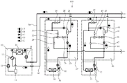
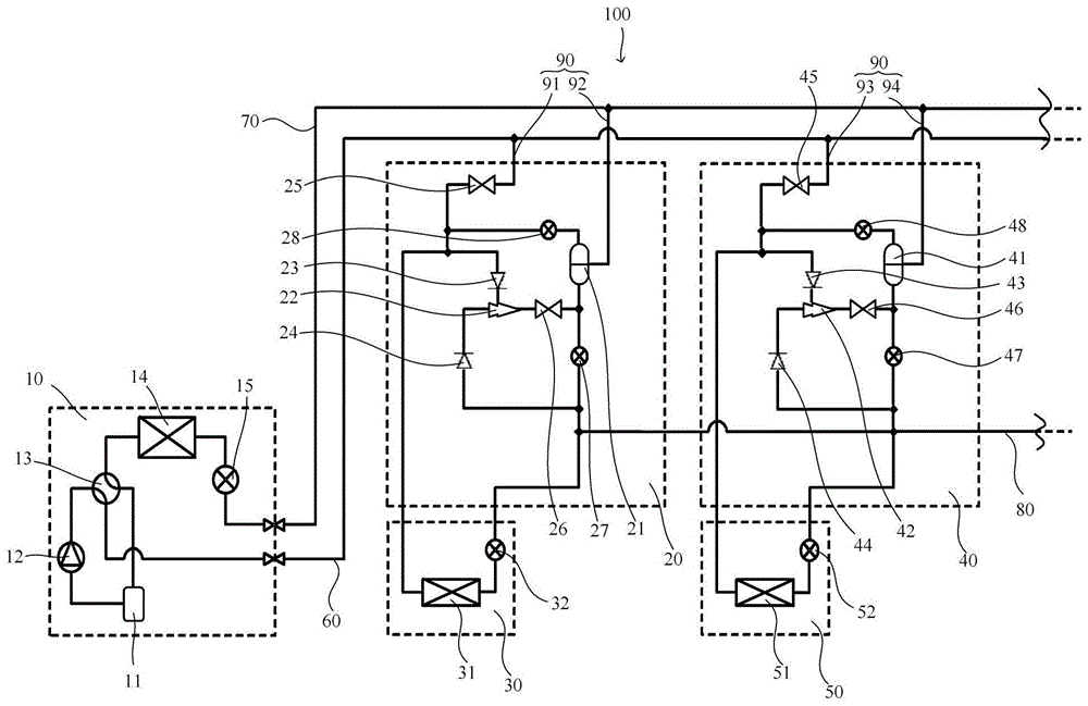
图1为本发明第一实施例提供的多联机空调100的结构示意图。Fig. 1 is a schematic structural diagram of a
图2为图1所示第一室内机30与第二室内机50同时制冷时的冷媒流向图。FIG. 2 is a flow diagram of refrigerant when the first
图3为图1所示第一室内机30与第二室内机50同时制热时的冷媒流向图。FIG. 3 is a flow diagram of refrigerant when the first
图4为图1所示第一室内机30制冷与第二室内机50制热时冷媒流向图。FIG. 4 is a flow diagram of refrigerant when the first
图5为图1所示第一室内机30制热与第二室内机50制冷时冷媒流向图。FIG. 5 is a flow diagram of refrigerant when the first
图6为图5中喷射泵42的结构示意图。FIG. 6 is a schematic structural diagram of the
附图标记说明:Explanation of reference signs:
100-多联机空调;10-室外机;11-储液器;12-压缩机;13-四通阀;14-第一热交换器;15-室外膨胀阀;20-第一中转单元;21-第一气液分离器;22-第一喷射泵;23-第一逆止阀;24-第二逆止阀;25-第一电磁阀;26-第二电磁阀;27-第一膨胀阀;28-第二膨胀阀;30-第一室内机;31-第二热交换器;32-第一室内膨胀阀;40-第二中转单元;41-第二气液分离器;411-气体腔;412-液体腔;42-第二喷射泵;421-混合部;422-第二压缩机;423-凝缩器;424-蒸发器;43-第三逆止阀;44-第四逆止阀;45-第三电磁阀;46-第四电磁阀;47-第三膨胀阀;48-第四膨胀阀;50-第二室内机;51-第三热交换器;52-第二室内膨胀阀;60-气管;70-液管;80-废热回收管。100-multi-split air conditioner; 10-outdoor unit; 11-accumulator; 12-compressor; 13-four-way valve; 14-first heat exchanger; 15-outdoor expansion valve; 20-first transfer unit; 21 - the first gas-liquid separator; 22 - the first injection pump; 23 - the first check valve; 24 - the second check valve; 25 - the first solenoid valve; 26 - the second solenoid valve; 27 - the first expansion Valve; 28-second expansion valve; 30-first indoor unit; 31-second heat exchanger; 32-first indoor expansion valve; 40-second transfer unit; 41-second gas-liquid separator; 411- Gas chamber; 412-liquid chamber; 42-second jet pump; 421-mixing part; 422-second compressor; 423-condenser; 424-evaporator; 43-third check valve; 44-fourth Check valve; 45-the third solenoid valve; 46-the fourth solenoid valve; 47-the third expansion valve; 48-the fourth expansion valve; 50-the second indoor unit; 51-the third heat exchanger; 52-the first Two indoor expansion valves; 60-gas pipe; 70-liquid pipe; 80-waste heat recovery pipe.
具体实施方式Detailed ways
为使本发明的上述目的、特征和优点能够更为明显易懂,下面结合附图对本发明的具体实施例做详细的说明。In order to make the above objects, features and advantages of the present invention more comprehensible, specific embodiments of the present invention will be described in detail below in conjunction with the accompanying drawings.
【第一实施例】【The first embodiment】
本发明实施例提供了一种多联机空调100,所述多联机空调100包括:室外机10、多个中转单元以及多个室内机;其中,多个所述中转单元,通过气管60与液管70连接至室外机10;多个所述室内机;多个所述室内机与多个所述中转单元一一对应连接。The embodiment of the present invention provides a
优选的,以所述中转单元以及所述室内机设置两个为例,参见图1-图3,所述中转单元包括:第一中转单元20以及第二中转单元40;所述室内机包括:第一室内机30以及第二室内机50;其中,第一中转单元20与第二中转单元40通过气管60与液管70连接至室外机10;第一室内机30连接至第一中转单元20,第二室内机50连接至第二中转单元;室外机10包括由配管依次连接的储液器11、压缩机12、四通阀13、第一热交换器14以及室外膨胀阀15。Preferably, taking the transfer unit and the indoor unit as an example, referring to Figures 1-3, the transfer unit includes: a
优选的,第一中转单元20与第二中转单元40内部设有管道90,管道90的设置实现了第一室内机30、第二室内机50与室外机10之间的连通,进一步的室外机10通过管道90实现对第一室内机30与第二室内机50的制热以及制冷的效果。Preferably, the
具体的,管道90包括:第一管道91、第二管道92、第三管道93以及第四管道94;其中,第一管道91与第二管道92设置于第一中转单元20,且第一管道91一端连接至气管60,第二管道92连接至液管70,第一室内机30连接在第一管道91与第二管道92之间;第三管道93与第四管道94设置于第二中转单元40,且第三管道93连接至气管60,第四管道94连接至液管70,第二室内机50连接在第三管道93与第四管道94之间;可以理解的是,第一中转单元20与第二中转单元40内部结构一致;多联机空调100还包括:废热回收管80,连接在第二管道92与第四管道94之间。Specifically, the
优选的,当所述中转单元有两个时,所述气液分离器包括:第一气液分离器21以及第二气液分离器41;其中,第一气液分离器21设置于第一中转单元20,第二气液分离器41设置于第二中转单元40;进一步的第一中转单元20还包括:第一喷射泵22;第一气液分离器21设置在第二管道92上,且位于废热回收管80与液管70之间;第一喷射泵22设置于第一管道91与第二管道92之间;进一步的,第一中转单元20内还设有第一膨胀阀27、第二膨胀阀28、第一电磁阀25以及第二电磁阀26,用于控制冷媒在第一中转单元20内部的流动。Preferably, when there are two transfer units, the gas-liquid separator includes: a first gas-
进一步的,第一中转单元20还设有第一逆止阀23与第二逆止阀24,分别设置在第一管道91与第一喷射泵22、以及第二管道92与第一喷射泵22之间,用于控制第一中转单元20内部冷媒在第一管道91、第二管道92与第一喷射泵22之间的流动,且第一逆止阀23与第二逆止阀24设置的方向相反。Further, the
再进一步的,第一室内机30设有第二热交换器31,第二室内机50设有第三热交换器51,且在连接第二热交换器31的第二管道92上设置有第一室内膨胀阀32,在连接第二热交换器51的第四管道94上设置有第二室内膨胀阀52。Still further, the first
优选的,第二室内机50以及第二中转单元40与第一室内机30以及第一中转单元20的结构以及连接关系一致,此处不再做一一赘述。Preferably, the structure and connection relationship of the second
优选的,在第一室内机30与第二室内机50同时制冷时,室外机10通过液管70向第一室内机30与第二室内机40输送高压液态冷媒,具体的,液管70中的高压液态冷媒输送至第一中转单元20与第二中转单元40的第二管道92与第四管道94后,再由第一室内膨胀阀32与第二室内膨胀阀52将所述高压液态冷媒转化为易于蒸发的低温低压二相冷媒,其中,所述低压二相冷媒中包括低压液态冷媒以及低压气态冷媒;进一步的,所述低压二相冷媒再经过第二热交换器31以及第三热交换器51完成换热,实现第一室内机30以及第二室内机50的制冷效果;经第二热交换器31与第三热交换器51换热产生的低压气态冷媒再由第一管道91与第三管道93输送至气管60,进一步的,输送至室外机10;其中,A为高压气态冷媒,B为高压液态冷媒,C为低压二相冷媒,D为低压气态冷媒,E为高压二相冷媒。Preferably, when the first
再进一步的,在第一室内机30与第二室内机50同时制冷的过程中,第一中转单元20内的第一电磁阀25、以及第一膨胀阀27处于打开状态,第二膨胀阀28以及第二电磁阀26处于关闭状态;同样的,在第二中转单元40中,第三电磁阀45与第三膨胀阀47处于打开状态,第四电磁阀46以及第四膨胀阀48处于关闭状态。Furthermore, during the cooling process of the first
可以理解的是,在第一室内机30与第二室内机50同时制冷的过程中,第一室内机30与第二室内机50的运行状态一致,故在此时,第一中转单元30与第二中转单元50中的喷射泵以及气液分离器不具有工作状态,在同时制冷的过程中,多联机空调100与现有技术中的连接空调运行过程一致,其中具体运行流程,此处不作赘述。It can be understood that, during the cooling process of the first
优选的,第一室内机30与第二室内机50在同时制热与同时制冷的原理一致,在第一室内机30与第二室内机50同时制热时,室外机10通过气管60向第一室内机30与第二室内机40输送高压气态冷媒;具体的,气管60中的高压气态冷媒输送至第一中转单元20与第二中转单元40的第一管道91与第三管道93后,经过第二热交换器31以及第三热交换器51完成换热,在完成换热后,产生的高压液态冷媒再由第二管道92以及第四管道94输送至液管70,进一步的在经液管70输送回室外机10。Preferably, the principle of simultaneous heating and cooling of the first
进一步的,同时制热与同时制冷时,除第一室内机30、第二室内机50与室外机10之间气液态流动方向相反外,第一中转单元20与第二中转单元40中各个开关的闭合状态也与同时制冷条件下一致,此处不再作一一赘述。Further, during simultaneous heating and simultaneous cooling, except that the gas-liquid flow direction between the first
【第二实施例】【Second Embodiment】
优选的,本发明第二实施例提供了另一种多联机空调100,室外机10在制冷为主体模式下,高压冷媒通过所述气液分离器分离为高压气态冷媒和高压液态冷媒,若任一所述室内机处于制热模式,则对其输送高压气态冷媒,若任一所述室内机处于制冷模式,则对其输送高压液态冷媒。处于制热模式的室内机的液体冷媒通过废热回收管80输送到处于制冷模式的室内机。所述气液分离器设置在液管70与所述室内机之间,所述气液分离器包括入口、气体出口和出口,处于制冷模式的所述室内机的气液分离器的所述出口与所述室内机冷媒入口连通,所述气体出口与气管60连通;处于制热模式的所述室内机的气液分离器的所述气体出口与所述室内机的冷媒入口连通,所述出口通过废热回收管80与处于制冷模式的所述室内机冷媒入口连通;所述入口与液管70连通;处于制热模式的所述室内机的冷媒出口通过废热回收管80与处于制冷模式的所述室内机冷媒入口连通。Preferably, the second embodiment of the present invention provides another
其中,制冷为主体模式表示:多联机空调100在制冷制热同时运转时,参考图4为例,第一室内机30制冷需求较大,第二室内机50制热需求相对较小,此时多联机空调100主要以制冷为主,即,此时可将多联机空调100运行状态记作:制冷为主体模式,且在此状态下,室外机10制热;可以理解的是,在制冷为主体模式下,第二室内机50可看作第一室内机30的第二室外机,通过第二室内机50与室外机10之间的配合,通过由液管70以及废热回收管80向第一室内机30输送的高压液态冷媒,提高了第一室内机30的制冷效率,进一步的满足了在制冷为主体模式下,用户对于制冷的需求。Wherein, the main mode of cooling means that: when the
进一步的,所述室内机与所述中转单元分别有两个时,在多联机空调100冷暖同时进行时,在室外机10为制冷为主体模式下,以第一室内机30制冷、第二室内机50制热为例;Further, when there are two indoor units and two transfer units, when the
参见图4,在制冷为主体模式下,通过抑制室外机10中第一热交换器14的风扇风量的大小,使其能够在室外机10配管中产生高压二相冷媒,即,高压气态冷媒与高压液态冷媒同时存在,通过液管70将所述高压二相冷媒由第二管道92输送至第一气液分离器21中,经第一气液分离器21进行气液分离后,高压液态冷媒由第一膨胀阀27输送至第一室内机30中,后经第一室内膨胀阀32进行降压处理后,产生低压二相冷媒,在进入第二热交换器31,从而实现第一室内机30制冷的目的,进一步的经过第二换热器31换热后的低压气态冷媒由第一管道91输送至气管60中,最后输送回室外机10内部,从而形成循环。Referring to Fig. 4, in the main mode of cooling, by suppressing the air volume of the fan of the
进一步的,第一室内机30制冷的过程中,第一中转单元20内的第一电磁阀25处于打开状态,第二电磁阀26处于闭合状态,第一膨胀阀27处于打开状态,第二膨胀阀28处于打开状态且调整第二膨胀阀28阀门开度较小,使其能够对由第一气液分离器21流向第一管道91之间的高压气态冷媒压力减小,进一步的再与第一管道91中的低压气态冷媒混合后,由气管60一起输送至室外机10中。Furthermore, during the cooling process of the first
优选的,在第二室内机50制热时,液管70中的高压二相冷媒由第四管道94输送至第二气液分离器41中,后经气液分离,高压气态冷媒经第四膨胀阀48输送至第三管道93中,进一步的输送至第二室内机50中进行热交换,经第三热交换器51完成热交换后形成高压液态冷媒;为保证第二室内机50中高压液态冷媒的充分利用,所述高压液态冷媒可经废热回收管80输送至第一室内机30中,进一步的由第一室内机30进行制冷处理;第二气液分离器41分离的高压液态冷媒可由第三膨胀阀47输送至废热回收管80中,与第二室内机50产生的高压液态冷媒混合后,输送至第一室内机30中,在此过程中,避免了第二室内机50制热时产生的高压液态冷媒的浪费。Preferably, when the second
进一步的,在第二室内机50制热的过程中,第三电磁阀45以及第四电磁阀46处于闭合状态,第四膨胀阀48处于完全打开状态;为避免第二气液分离器41分离的高压液态冷媒对第二室内机50制热产生影响,故调整第三膨胀阀47的开口较小。Further, during the heating process of the second
优选的,在一种情形下,在制冷为主体模式时,对于制热要求相对较低时,也可以省略第一中转单元20以及第二中转单元40内的第一气液分离器21以及第二气液分离器41。可将来自室外机10的高压液态冷媒(例如冷凝温度50℃)流入第一室内机30以及第二室内机50中,仅将显热用于制热,即在第二室内机50制热时,将高压液体冷媒的温度用于制热,在此过程中,冷媒状态不发生相变。Preferably, in one case, when cooling is the main mode and the requirement for heating is relatively low, the first gas-
【第三实施例】[Third embodiment]
优选的,本发明第三实施例提供了另一种多联机空调100,本发明实施例中,每个所述中转单元包括喷射泵,室外机10在制热为主体模式下,若任一所述室内机处于制热模式,则对其输送高压气态冷媒,经过所述室内机的高压液态冷媒中的一部分输送至所述液管;另一部分通过废热回收管80输送到处于制冷模式的室内机的中转单元。废热回收管80输送到处于制冷模式的室内机的中转单元中的一部分高压液态冷媒输送至处于制冷模式的所述室内机中;另一部分输送至所述喷射泵中;其中,输送至所述喷射泵中的高压液态冷媒用于对处于制冷模式的室内机产生的低压气态冷媒进行引流。室外机10在制热为主体模式下,处于制热模式下的室内机的冷媒出口与所述气液分离器的入口连通;处于制冷模式下的室内机的冷媒出口经所述喷射泵与所述入口连通;所述气液分离器的出口与所述液管连通。所述喷射泵设有:驱动流入口、吸引流入口以及喷射泵出口;室外机10在制热为主体模式下,处于制冷模式下的室内机的冷媒出口与所述吸引流入口连通;所述驱动流入口与废热回收管80连通;所述喷射泵出口与所述气液分离器的入口连通。Preferably, the third embodiment of the present invention provides another
其中,制热为主体模式表示:多联机空调100制冷制热同时运转时,参考图5为例,第一室内机30制热需求较大,第二室内机50制冷需求相对较小,此时多联机空调100主要以制热为主,即,此时可将多联机空调100运行状态记作:制热为主体模式,且在此状态下,室外机10制冷;可以理解的是,在制热为主体模式下,用户对于制冷的需求较低,可将第一室内机30当做第二室内机50的外机,第一室内机30可提供第二室内机50所需求的高压液态冷媒,此时废热回收管80主要起到向第二室内机50输送高压液态冷媒的作用。Among them, the main mode of heating means: when the
进一步的,参见图5,所述室内机与所述中转单元分别有两个时,在制热为主体模式时,以第一室内机30制热,第二室内机50制冷为例:室外机10经气管60由第一管道91向第一室内机30输送高压气态冷媒,在第二热交换器31与室内空气形成热交换之后形成高压液态冷媒,其中,所产生的高压液态冷媒中的一部分由第二管道92经过第一膨胀阀27输送至液管70,再由液管70输送回室外机10中形成循环;所产生的高压液态冷媒中另一部分由第二管道92经废热回收管80输送第二中转单元40中,进一步的经第二室内膨胀阀52进行降压后,由第三热交换器51进行热交换后,由第三管道93依次经过第三逆止阀42、第二喷射泵42、第四电磁阀46、第二气液分离器41以及液管70输送回室外机10中完成循环;与此同时,在第二管道92向第二中转单元40输送的高压液态冷媒中的另一部分由第四管道94经第四逆止阀44、第二喷射泵42、第四电磁阀46、第二气液分离器41以及液管70输送回室外机10中,完成循环。Further, referring to Fig. 5, when there are two indoor units and two transfer units, when heating is the main mode, take the first indoor unit 30 for heating and the second indoor unit 50 for cooling as an example: the outdoor unit 10 The high-pressure gaseous refrigerant is delivered from the first pipe 91 to the first indoor unit 30 through the gas pipe 60, and the high-pressure liquid refrigerant is formed after the heat exchange between the second heat exchanger 31 and the indoor air, wherein a part of the generated high-pressure liquid refrigerant The second pipe 92 is sent to the liquid pipe 70 through the first expansion valve 27, and then sent back to the outdoor unit 10 by the liquid pipe 70 to form a cycle; the other part of the generated high-pressure liquid refrigerant is passed through the second pipe 92 through the waste heat recovery pipe 80 After being transported to the second transfer unit 40, the pressure is further reduced through the second indoor expansion valve 52, and after heat exchange is performed by the third heat exchanger 51, the third pipeline 93 passes through the third check valve 42, the second The jet pump 42, the fourth electromagnetic valve 46, the second gas-liquid separator 41 and the liquid pipe 70 are sent back to the outdoor unit 10 to complete the cycle; at the same time, the high-pressure liquid refrigerant sent to the second transfer unit 40 in the second pipe 92 The other part is transported back to the outdoor unit 10 by the fourth pipeline 94 through the fourth check valve 44, the second jet pump 42, the fourth solenoid valve 46, the second gas-liquid separator 41 and the liquid pipe 70 to complete the cycle.
进一步的,在第一室内机30制热的过程中,第一中转单元20内的第一电磁阀25处于打开状态,第二电磁阀26处于闭合状态,第一膨胀阀27处于打开状态且第一膨胀阀27阀门开度较小,第二膨胀阀28处于闭合状态。Furthermore, during the heating process of the first
再进一步的,在第二室内机50制冷的过程中,第三电磁阀45处于关闭状态,第四电磁阀46处于打开状态,第三膨胀阀47以及第四膨胀阀48处于闭合状态。Still further, during the cooling process of the second
优选的,在制热为主体模式时,在第二中转单元中输送的高压液态冷媒大多分配到第二喷射泵42侧,作为输送到第二室内机50的冷媒的驱动流。另外,被输送到第二室内机50的冷媒被第二喷射泵42从蒸发升压后,通过液管70返回到室外机10。作为使用制热的第一中转单元20内的第二膨胀阀27为了使返回液冷媒流向制冷侧的第二中转单元40中,可调整为全闭,但需根据制冷的比例调整开度(使用制冷的第三管道93以及第四管道94压损过大的情况等)。Preferably, when the heating is the main mode, most of the high-pressure liquid refrigerant delivered in the second transfer unit is distributed to the
优选的,参见图6,在制热为主体模式时,第二室内机50制冷,从第二逆止阀44流向第二喷射泵42的高压液态冷媒作为驱动流由喷嘴高速喷射,在内部形成低压空间,将外部由第一逆止阀43流向第二喷射泵42的低压气态冷媒作为吸引流吸入第二喷射泵42内部,在第二喷射泵42中的混合部421混合,混合后的流体在扩散器中减少速度的同时,几乎无损的恢复其动能,进一步的实现恢复压力的目的。Preferably, referring to Fig. 6, when the heating mode is the main mode, the second
其中,PH为作为驱动流的高压液态冷媒进入第二喷射泵42时的初始压力值,PL为作为吸引流的低压气态冷媒进入第二喷射泵42时的初始压力值,PS为驱动流与吸引流混合后所达到的最小压力值,PD为混合后的流体在第二喷射泵42出口时的压力值。Among them, PH is the initial pressure value when the high-pressure liquid refrigerant as the driving flow enters the
进一步的,再输送至第二气液分离器41中的气体腔411与液体腔412内,此时由于第四膨胀阀48处于闭合状态,分离后的气态冷媒不会由第四膨胀阀48进入气管60中,此时可将第二气液分离器41当做存储器,当第二喷射泵42中的低压气态冷媒与高压液态冷媒不能充分混合时,混合流体可在第二气液分离器41内进一步的实现缓冲,最后再将最终的混合流体输送至液管70中,进一步的输送至室外10中实现循环,可以理解得是,混合流体中以高压液体为主,其中混合有少量气体;经第二气液分离器41的混合流体还能通过增加配管的方式将气液分离器41中的混合流体进行分离进一步的再由新设置的配管输送至第二压缩机422与凝缩器423实现制热或者经过蒸发器实现制冷的目的,在此过程中制冷或者制热过程与现有技术中方式一致,此处不在作一一赘述。Furthermore, it is transported to the
虽然本发明披露如上,但本发明并非限定于此。任何本领域技术人员,在不脱离本发明的精神和范围内,均可作各种更动与修改,因此本发明的保护范围应当以权利要求所限定的范围为准。Although the present invention is disclosed above, the present invention is not limited thereto. Any person skilled in the art can make various changes and modifications without departing from the spirit and scope of the present invention, so the protection scope of the present invention should be based on the scope defined in the claims.
Claims (10)
Priority Applications (1)
| Application Number | Priority Date | Filing Date | Title |
|---|---|---|---|
| CN202110519614.0A CN115342425B (en) | 2021-05-12 | 2021-05-12 | A multi-connected air conditioner |
Applications Claiming Priority (1)
| Application Number | Priority Date | Filing Date | Title |
|---|---|---|---|
| CN202110519614.0A CN115342425B (en) | 2021-05-12 | 2021-05-12 | A multi-connected air conditioner |
Publications (2)
| Publication Number | Publication Date |
|---|---|
| CN115342425A true CN115342425A (en) | 2022-11-15 |
| CN115342425B CN115342425B (en) | 2025-02-11 |
Family
ID=83977817
Family Applications (1)
| Application Number | Title | Priority Date | Filing Date |
|---|---|---|---|
| CN202110519614.0A Active CN115342425B (en) | 2021-05-12 | 2021-05-12 | A multi-connected air conditioner |
Country Status (1)
| Country | Link |
|---|---|
| CN (1) | CN115342425B (en) |
Citations (9)
| Publication number | Priority date | Publication date | Assignee | Title |
|---|---|---|---|---|
| JP2002089988A (en) * | 2000-09-21 | 2002-03-27 | Mitsubishi Electric Corp | Air conditioner, operation method of air conditioner |
| JP2007298205A (en) * | 2006-04-28 | 2007-11-15 | Toshiba Kyaria Kk | Air conditioner indoor unit |
| CN102072531A (en) * | 2010-12-29 | 2011-05-25 | 广东美的电器股份有限公司 | Four-pipe type heat recovery multi-split air conditioning system |
| CN104833010A (en) * | 2015-05-25 | 2015-08-12 | 广东美的暖通设备有限公司 | Outdoor unit of heat recovery VRF air conditioning system and heat recovery VRF air conditioning system |
| CN106247508A (en) * | 2016-09-12 | 2016-12-21 | 青岛海信日立空调系统有限公司 | Use the air conditioner heat pump system of ejector, air-conditioner and air-conditioner control method |
| CN110779080A (en) * | 2019-10-10 | 2020-02-11 | 珠海格力电器股份有限公司 | Continuous heating heat recovery air conditioner outdoor system, heat recovery air conditioner and using method thereof |
| CN112032825A (en) * | 2020-08-13 | 2020-12-04 | 青岛海尔空调电子有限公司 | Air conditioning system and compressor waste heat recovery method thereof |
| CN112178969A (en) * | 2020-10-28 | 2021-01-05 | 珠海格力电器股份有限公司 | Multi-line system and its control method |
| CN214791448U (en) * | 2021-05-12 | 2021-11-19 | 宁波奥克斯电气股份有限公司 | A multi-connected air conditioner |
-
2021
- 2021-05-12 CN CN202110519614.0A patent/CN115342425B/en active Active
Patent Citations (10)
| Publication number | Priority date | Publication date | Assignee | Title |
|---|---|---|---|---|
| JP2002089988A (en) * | 2000-09-21 | 2002-03-27 | Mitsubishi Electric Corp | Air conditioner, operation method of air conditioner |
| JP2007298205A (en) * | 2006-04-28 | 2007-11-15 | Toshiba Kyaria Kk | Air conditioner indoor unit |
| CN102072531A (en) * | 2010-12-29 | 2011-05-25 | 广东美的电器股份有限公司 | Four-pipe type heat recovery multi-split air conditioning system |
| CN104833010A (en) * | 2015-05-25 | 2015-08-12 | 广东美的暖通设备有限公司 | Outdoor unit of heat recovery VRF air conditioning system and heat recovery VRF air conditioning system |
| US20170191715A1 (en) * | 2015-05-25 | 2017-07-06 | Gd Midea Heating & Ventilating Equipment Co., Ltd. | Outdoor unit for heat recovery vrf air conditioning system and heat recovery vrf air conditioning system |
| CN106247508A (en) * | 2016-09-12 | 2016-12-21 | 青岛海信日立空调系统有限公司 | Use the air conditioner heat pump system of ejector, air-conditioner and air-conditioner control method |
| CN110779080A (en) * | 2019-10-10 | 2020-02-11 | 珠海格力电器股份有限公司 | Continuous heating heat recovery air conditioner outdoor system, heat recovery air conditioner and using method thereof |
| CN112032825A (en) * | 2020-08-13 | 2020-12-04 | 青岛海尔空调电子有限公司 | Air conditioning system and compressor waste heat recovery method thereof |
| CN112178969A (en) * | 2020-10-28 | 2021-01-05 | 珠海格力电器股份有限公司 | Multi-line system and its control method |
| CN214791448U (en) * | 2021-05-12 | 2021-11-19 | 宁波奥克斯电气股份有限公司 | A multi-connected air conditioner |
Also Published As
| Publication number | Publication date |
|---|---|
| CN115342425B (en) | 2025-02-11 |
Similar Documents
| Publication | Publication Date | Title |
|---|---|---|
| JP4639541B2 (en) | Cycle using ejector | |
| CN103759449B (en) | The two-stage steam compression type circulatory system of dual jet synergy | |
| CN102563945B (en) | Refrigeration circulating system with double-stage-injection ejector | |
| CN115574394B (en) | Air conditioning system and control method | |
| CN109386989B (en) | Two-pipe jet enthalpy-increasing outdoor unit and multi-split system | |
| CN108800678B (en) | Air Conditioning System | |
| CN102187165A (en) | Multiple evaporation system | |
| WO2015158138A1 (en) | Refrigeration device | |
| CN101135505A (en) | A Vapor Compression Refrigeration System Containing an Ejector | |
| CN203550275U (en) | Pump-free spraying-type refrigerating system | |
| CN108800393B (en) | Air conditioning system | |
| CN105737459A (en) | Air conditioner | |
| CN109269136B (en) | Air Conditioning System | |
| CN109682134A (en) | Gas-liquid separator and heat pump system | |
| CN205641654U (en) | Cascade refrigeration circulation system and have its refrigerating plant | |
| CN106931675B (en) | The injecting type circulatory system and air-conditioning | |
| CN214791448U (en) | A multi-connected air conditioner | |
| CN113483422A (en) | Novel cooling and refrigerating integrated device | |
| CN115342425A (en) | Multi-split air conditioner | |
| CN109099620B (en) | Air conditioning system | |
| CN205641697U (en) | Air -conditioner | |
| CN108344195A (en) | Recycle the one machine dual temperature refrigeration system of two level injection of expansion work | |
| CN218120237U (en) | heat exchange system | |
| CN215412278U (en) | Novel cooling and refrigerating integrated device | |
| CN110617591A (en) | Intelligent vortex injection energy-saving air conditioner |
Legal Events
| Date | Code | Title | Description |
|---|---|---|---|
| PB01 | Publication | ||
| PB01 | Publication | ||
| SE01 | Entry into force of request for substantive examination | ||
| SE01 | Entry into force of request for substantive examination | ||
| CB02 | Change of applicant information |
Country or region after: China Address after: 315191 No. 1166 Mingguang North Road, Jiangshan Town, Ningbo, Zhejiang, Yinzhou District Applicant after: NINGBO AUX ELECTRIC Co.,Ltd. Applicant after: AUX AIR CONDITIONING LIMITED BY SHARE Ltd. Address before: No. 1166 Mingguang North Road, Jiangshan Town, Ningbo, Zhejiang, Yinzhou District Applicant before: NINGBO AUX ELECTRIC Co.,Ltd. Country or region before: China Applicant before: AUX AIR CONDITIONING LIMITED BY SHARE Ltd. |
|
| CB02 | Change of applicant information | ||
| GR01 | Patent grant | ||
| GR01 | Patent grant |