CN115351663A - Grinding device for tunnel secondary lining trolley template - Google Patents
Grinding device for tunnel secondary lining trolley template Download PDFInfo
- Publication number
- CN115351663A CN115351663A CN202211144870.7A CN202211144870A CN115351663A CN 115351663 A CN115351663 A CN 115351663A CN 202211144870 A CN202211144870 A CN 202211144870A CN 115351663 A CN115351663 A CN 115351663A
- Authority
- CN
- China
- Prior art keywords
- connecting pipe
- dust hood
- shaft
- template
- lining trolley
- Prior art date
- Legal status (The legal status is an assumption and is not a legal conclusion. Google has not performed a legal analysis and makes no representation as to the accuracy of the status listed.)
- Granted
Links
- 239000000428 dust Substances 0.000 claims abstract description 99
- 238000005498 polishing Methods 0.000 claims abstract description 34
- 238000005096 rolling process Methods 0.000 claims description 35
- 230000006835 compression Effects 0.000 claims description 27
- 238000007906 compression Methods 0.000 claims description 27
- 238000009423 ventilation Methods 0.000 claims description 10
- 230000000903 blocking effect Effects 0.000 claims description 7
- 238000009415 formwork Methods 0.000 claims description 2
- 238000007789 sealing Methods 0.000 claims description 2
- 230000000149 penetrating effect Effects 0.000 claims 2
- 230000036541 health Effects 0.000 abstract description 4
- 238000010521 absorption reaction Methods 0.000 description 3
- JEIPFZHSYJVQDO-UHFFFAOYSA-N iron(III) oxide Inorganic materials O=[Fe]O[Fe]=O JEIPFZHSYJVQDO-UHFFFAOYSA-N 0.000 description 3
- XEEYBQQBJWHFJM-UHFFFAOYSA-N Iron Chemical compound [Fe] XEEYBQQBJWHFJM-UHFFFAOYSA-N 0.000 description 2
- 238000010276 construction Methods 0.000 description 2
- 230000008878 coupling Effects 0.000 description 2
- 238000010168 coupling process Methods 0.000 description 2
- 238000005859 coupling reaction Methods 0.000 description 2
- 206010010904 Convulsion Diseases 0.000 description 1
- 229910000831 Steel Inorganic materials 0.000 description 1
- 230000036461 convulsion Effects 0.000 description 1
- 238000010586 diagram Methods 0.000 description 1
- 230000000694 effects Effects 0.000 description 1
- 229910052742 iron Inorganic materials 0.000 description 1
- 239000000463 material Substances 0.000 description 1
- 238000000034 method Methods 0.000 description 1
- 238000012986 modification Methods 0.000 description 1
- 230000004048 modification Effects 0.000 description 1
- 230000008569 process Effects 0.000 description 1
- 239000010959 steel Substances 0.000 description 1
- 230000005641 tunneling Effects 0.000 description 1
Images





Classifications
-
- B—PERFORMING OPERATIONS; TRANSPORTING
- B24—GRINDING; POLISHING
- B24B—MACHINES, DEVICES, OR PROCESSES FOR GRINDING OR POLISHING; DRESSING OR CONDITIONING OF ABRADING SURFACES; FEEDING OF GRINDING, POLISHING, OR LAPPING AGENTS
- B24B19/00—Single-purpose machines or devices for particular grinding operations not covered by any other main group
- B24B19/20—Single-purpose machines or devices for particular grinding operations not covered by any other main group for grinding dies
-
- B—PERFORMING OPERATIONS; TRANSPORTING
- B24—GRINDING; POLISHING
- B24B—MACHINES, DEVICES, OR PROCESSES FOR GRINDING OR POLISHING; DRESSING OR CONDITIONING OF ABRADING SURFACES; FEEDING OF GRINDING, POLISHING, OR LAPPING AGENTS
- B24B27/00—Other grinding machines or devices
- B24B27/033—Other grinding machines or devices for grinding a surface for cleaning purposes, e.g. for descaling or for grinding off flaws in the surface
-
- B—PERFORMING OPERATIONS; TRANSPORTING
- B24—GRINDING; POLISHING
- B24B—MACHINES, DEVICES, OR PROCESSES FOR GRINDING OR POLISHING; DRESSING OR CONDITIONING OF ABRADING SURFACES; FEEDING OF GRINDING, POLISHING, OR LAPPING AGENTS
- B24B55/00—Safety devices for grinding or polishing machines; Accessories fitted to grinding or polishing machines for keeping tools or parts of the machine in good working condition
- B24B55/06—Dust extraction equipment on grinding or polishing machines
-
- Y—GENERAL TAGGING OF NEW TECHNOLOGICAL DEVELOPMENTS; GENERAL TAGGING OF CROSS-SECTIONAL TECHNOLOGIES SPANNING OVER SEVERAL SECTIONS OF THE IPC; TECHNICAL SUBJECTS COVERED BY FORMER USPC CROSS-REFERENCE ART COLLECTIONS [XRACs] AND DIGESTS
- Y02—TECHNOLOGIES OR APPLICATIONS FOR MITIGATION OR ADAPTATION AGAINST CLIMATE CHANGE
- Y02P—CLIMATE CHANGE MITIGATION TECHNOLOGIES IN THE PRODUCTION OR PROCESSING OF GOODS
- Y02P70/00—Climate change mitigation technologies in the production process for final industrial or consumer products
- Y02P70/10—Greenhouse gas [GHG] capture, material saving, heat recovery or other energy efficient measures, e.g. motor control, characterised by manufacturing processes, e.g. for rolling metal or metal working
Landscapes
- Engineering & Computer Science (AREA)
- Mechanical Engineering (AREA)
- Cleaning In General (AREA)
Abstract
The invention provides a grinding device for a tunnel secondary lining trolley template, which belongs to the technical field of grinding devices and comprises a support, a dust hood, a grinding piece, an elastic assembly and an exhaust fan. The suction hood is connected with the support, and the suction hood can move along the circumference and the length direction of outer arched surface, and the suction hood is the open end towards the one end of outer arched surface. The polishing part is provided with a connecting part and a polishing part fixedly connected with the connecting part, the connecting part is positioned in the dust hood, the polishing part is positioned on one side of the connecting part facing the outer arched surface, and the connecting part is connected with the dust hood in a sliding manner. The elastic component is positioned in the dust hood and is abutted against the connecting part. The exhaust fan is connected with the dust hood, and the air inlet is communicated with the interior of the dust hood. The grinding device for the template of the tunnel secondary lining trolley, provided by the invention, can avoid the problem that the dust generated during grinding can influence the health of operators when the outer arched surface of the template in the secondary lining trolley is ground by a handheld tool.
Description
Technical Field
The invention belongs to the technical field of polishing devices, and particularly relates to a polishing device for a tunnel two-lining trolley template.
Background
In the tunneling process, a secondary lining construction needs to be carried out by using a secondary lining trolley. Before secondary lining construction, the outer arched surface of a template in a secondary lining trolley needs to be polished, so that rust or sundries on the outer arched surface are removed, and the appearance quality of a concrete surface after demoulding is ensured. Traditional mode of polishing is for letting instruments such as workman's handheld angle mill, electrician's steel brush to external arch face polish, and the dust when polishing can influence operating personnel's health.
Disclosure of Invention
The invention aims to provide a grinding device for a template of a tunnel secondary lining trolley, and aims to solve the problem that dust generated during grinding affects the health of operators when an outer arched surface of the template in the secondary lining trolley is ground by a handheld tool.
In order to achieve the purpose, the invention adopts the technical scheme that: the utility model provides a grinding device for two lining platform truck templates in tunnel, includes support, suction hood, polishes piece, elastic component and air exhauster. The dust hood is positioned on one side, opposite to the outer arched surface of the template, of the template in the two-lining trolley, the dust hood is connected with the support, the dust hood can move along the circumferential direction and the length direction of the outer arched surface, and one end, facing the outer arched surface, of the dust hood is an opening end. The piece of polishing have connecting portion and with connecting portion fixed connection's the portion of polishing, connecting portion are located in the suction hood, the portion of polishing is located connecting portion orientation one side of outer arched surface, connecting portion with suction hood sliding connection, the slip of connecting portion can make the portion of polishing compresses tightly or keeps away from outer arched surface. The elastic assembly is located in the dust hood and abutted against the connecting portion, and the elastic force of the elastic assembly is used for driving the connecting portion to slide so that the polishing portion compresses the outer arched surface. The exhaust fan is connected with the dust hood and the air inlet is communicated with the interior of the dust hood. The collecting device is used for collecting dust in the gas extracted from the dust hood by the exhaust fan.
In a possible implementation manner, the grinding device for the tunnel secondary lining trolley template further comprises a guide shaft. The guiding axle is two, the guiding axle is followed the slip direction setting of connecting portion, the guiding axle with connecting portion are kept away from the fixed surface of portion of polishing is connected and is slided and pierce through the suction hood is kept away from the diapire of the open end of suction hood. The elastic assembly comprises two first compression springs, the two first compression springs are respectively sleeved on the two guide shafts, and two ends of each first compression spring are respectively abutted to the connecting portion and the bottom wall.
In a possible implementation manner, the grinding device for the tunnel secondary lining trolley template further comprises a limiting plate and a pushing bolt. The limiting plate is perpendicular to the guide shafts, the limiting plate and the two end faces, far away from the connecting portion, of the guide shafts are fixedly attached to each other, and the limiting plate is provided with a first threaded hole parallel to the guide shafts in the hole depth direction. The screw rod of the ejector bolt penetrates through the first threaded hole and is in threaded connection with the first threaded hole, and the ejector bolt is used for extruding the bottom wall of the dust hood, so that the connecting part slides and extrudes the first compression spring.
In one possible implementation, the grinding device for the tunnel secondary lining trolley template further comprises an arch piece, a rolling shaft and a connecting pipe. The arch-shaped part is fixedly connected with the support, the arch-shaped part is provided with arch holes, the hole depth direction of each arch hole is parallel to the length direction of the outer arch surface, and the arch holes are identical to the arch direction of the outer arch surface and are annularly arranged outside the outer arch surface. The rolling shaft is arranged along the length direction of the outer arched surface, the rolling shaft penetrates through the arched hole in a sliding mode, the side wall of the rolling shaft is provided with two limiting portions protruding outwards, and the two limiting portions are located on the two sides of the arched piece in the axial direction of the rolling shaft respectively and are attached to the arched piece. The connecting pipe coaxially slides to penetrate through the rolling shaft, one end of the connecting pipe is fixedly connected with the dust hood and communicated with the interior of the dust hood, and the other end of the connecting pipe is connected with the collecting device.
In a possible implementation manner, the side wall of the connecting pipe is provided with an elongated protrusion protruding outwards, and the length direction of the elongated protrusion is arranged along the length direction of the connecting pipe and penetrates through the rolling shaft in a sliding manner.
In a possible implementation manner, the grinding device for the tunnel secondary lining trolley template further comprises a driving shaft, a driving rod, a U-shaped plate and a driving motor. The driving shaft is parallel to the connecting pipe and is rotatably connected with the bracket, the driving shaft is positioned on one side of the connecting pipe in the radial direction, and the rolling path of the rolling shaft surrounds the outside of the driving shaft. One end of the driving rod is perpendicular to and fixedly connected with the driving shaft. The U-shaped plate is slidably sleeved outside the connecting pipe, the U-shaped plate comprises a fixing part and two parallel pushing parts fixedly arranged on the fixing part, and the fixing part is vertically fixed at the other end of the driving rod. The driving motor is fixedly arranged on the support, an output shaft of the driving motor is connected with the driving shaft, and the driving motor is used for driving the driving shaft to rotate so that one of the pushing parts can push the connecting pipe, and then the rolling shaft rolls.
In a possible implementation, rectangular shape arch is located the connecting pipe orientation the lateral part of fixed part, rectangular shape arch orientation the surface of fixed part is equipped with a plurality of second screw holes, the second screw hole is the blind hole, and is a plurality of the second screw hole is followed the length direction equipartition of connecting pipe, a grinding device for two lining platform truck templates in tunnel still includes sliding shaft, location axle, holding ring and pneumatic cylinder. The sliding shaft is parallel to the connecting pipe and penetrates into the fixing part in a sliding mode. One end of the positioning shaft penetrates through one of the second threaded holes and is provided with a first external thread in threaded connection with the penetrated second threaded hole. The positioning ring is sleeved outside the positioning shaft in a sliding manner and is fixedly connected with the sliding shaft. The cylinder body of pneumatic cylinder with U template fixed connection, the piston rod of pneumatic cylinder can follow the length direction of connecting pipe is flexible and with sliding shaft fixed connection.
In a possible implementation manner, one end of the connecting pipe, which is far away from the dust hood, is provided with a second external thread, and the collecting device comprises a collecting tank and a filter screen. The terminal surface of the first end of holding vessel be equipped with the coaxial third screw hole of holding vessel, the holding vessel passes through third screw hole cover is located outside the second external screw thread and with the external screw thread threaded connection of second, the terminal surface of the second end of holding vessel is equipped with ventilative hole. The filter screen is fixedly arranged in the collection tank and covers the ventilation hole. The exhaust fan is fixedly arranged on the end face of the second end, and the air inlet covers the ventilation hole.
In a possible implementation, the coaxial apical axis that pushes away that wears to be equipped with in the connecting pipe, push away the apical axis with connecting pipe fixed connection and with first annular gap has between the connecting pipe, the one end that pushes away the apical axis extends to the connecting pipe is kept away from one side of suction hood, collection device still includes shutoff piece, fixed axle and second compression spring. The blocking piece is located in the collecting tank and has a second annular gap with the inside wall of the collecting tank. The fixed axle is two, the fixed axle with the connecting pipe is parallel and with shutoff piece fixed connection, the fixed axle slides and pierces through first end just the fixed axle is located the lateral wall of the outer one end of collection jar has outside convex butt portion. The two second compression springs are respectively sleeved on the fixed shaft in a sliding manner, and two ends of each second compression spring are respectively abutted to the first end and the corresponding abutting part. Wherein, work as collecting tank threaded connection in when on the connecting pipe, push away the apical axis and can push away the shutoff piece is kept away from first end, work as collecting tank disconnection with during the threaded connection of connecting pipe, second compression spring's resilience force can make the fixed axle drive the shutoff piece is close to first end, in order to realize sealing the third screw hole.
In a possible implementation, the surface of the closure facing the second end is a conical surface, which is arranged coaxially with the collection tank and has a conical tip facing the second end.
In the embodiment of the application, elastic component's elasticity makes the portion of polishing compress tightly outer arched surface, drive dust absorption cover removes along the circumference and the length direction of outer arched surface, just can make the portion of polishing polish iron rust or debris on outer arched surface, the air exhauster can follow the interior convulsions of dust absorption cover through the air intake, the dust that produces when polishing outer arched surface can get into in the dust absorption cover and along with the air current by the suction dust cover together, thereby be collected by collection device, so can avoid polishing the outer arched surface of the template in two lining platform trucks through handheld tool, dust when polishing can influence operating personnel's healthy problem.
Drawings
In order to more clearly illustrate the technical solutions in the embodiments of the present invention, the drawings used in the embodiments or the prior art descriptions will be briefly described below, and it is obvious that the drawings in the following description are only some embodiments of the present invention, and it is obvious for those skilled in the art that other drawings can be obtained according to the drawings without creative efforts.
Fig. 1 is a schematic axial structure diagram of a grinding device for a tunnel two-lining trolley template according to an embodiment of the present invention;
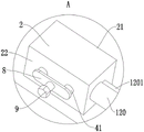
FIG. 2 is an enlarged schematic view of a portion A of FIG. 1;
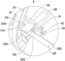
FIG. 3 is an enlarged schematic view of a portion B of FIG. 1;
FIG. 4 is an enlarged schematic view of a portion C of FIG. 1;
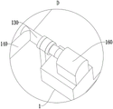
FIG. 5 is an enlarged schematic view of a portion D of FIG. 1;
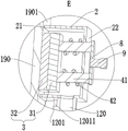
fig. 6 is a schematic cross-sectional axial view of a grinding device for a template of a tunnel secondary lining trolley according to an embodiment of the present invention;
FIG. 7 is an enlarged schematic view of a portion E of FIG. 6;
FIG. 8 is an enlarged view of a portion F of FIG. 6;
FIG. 9 is an enlarged schematic view of a portion G of FIG. 6;
fig. 10 is an enlarged schematic view of a portion H in fig. 6.
In the figure: 1. a support; 2. a dust hood; 21. an open end; 22. a bottom wall; 3. polishing the workpiece; 31. a connecting portion; 32. a polishing part; 41. a guide shaft; 42. a first compression spring; 5. an exhaust fan; 61. a sliding shaft; 62. positioning the shaft; 63. a positioning ring; 64. a hydraulic cylinder; 7. a collection device; 71. a collection tank; 711. a first end; 712. a second end; 713. a ventilation hole; 714. an extension portion; 72. a filter screen; 73. pushing the top shaft; 731. a first annular gap; 74. a blocking piece; 741. a second annular gap; 742. a conical surface; 75. a fixed shaft; 751. an abutting portion; 76. a second compression spring; 8. a limiting plate; 9. pushing the bolt; 10. an arch; 101. an arch-shaped hole; 110. a roll axis; 1101. a limiting part; 120. a connecting pipe; 1201. the strip-shaped bulge; 12011. a second threaded hole; 130. a drive shaft; 140. a drive rod; 150. a U-shaped plate; 1501. a fixed part; 1502. a pushing part; 160. a drive motor; 170. a limiting member; 180. a hold-down bolt; 190. a template; 1901. an outer arched surface; 1902. an inner arcuate surface.
Detailed Description
In order to make the technical problems, technical solutions and advantageous effects to be solved by the present invention more clearly apparent, the present invention is further described in detail below with reference to the accompanying drawings and embodiments. It should be understood that the specific embodiments described herein are merely illustrative of the invention and are not intended to limit the invention.
Referring to fig. 1, fig. 2, fig. 4, fig. 6, fig. 7 and fig. 9, the grinding device for a tunnel secondary lining trolley template provided by the present invention will now be described. The grinding device for the tunnel secondary lining trolley template comprises a support 1, a dust hood 2, a grinding piece 3, an elastic component and an exhaust fan 5. The dust hood 2 is positioned on one side of the template 190 in the two-lining trolley, which is opposite to the outer arched surface 1901 of the template 190, the dust hood 2 is connected with the bracket 1, the dust hood 2 can move along the circumferential direction and the length direction of the outer arched surface 1901, and one end of the dust hood 2, which faces the outer arched surface 1901, is an opening end 21. The polishing member 3 has a connecting portion 31 and a polishing portion 32 fixedly connected to the connecting portion 31, the connecting portion 31 is located in the dust hood 2, the polishing portion 32 is located on one side of the connecting portion 31 facing the outer arched surface 1901, the connecting portion 31 is slidably connected to the dust hood 2, and the polishing portion 32 can be pressed or separated from the outer arched surface 1901 by sliding of the connecting portion 31. The elastic component is located in the dust hood 2 and abutted to the connecting portion 31, and the elastic force of the elastic component is used for driving the connecting portion 31 to slide so that the polishing portion 32 compresses the outer arched surface 1901. The exhaust fan 5 is connected with the dust hood 2 and the air inlet is communicated with the interior of the dust hood 2. The collecting device 7 is used for collecting dust in the gas pumped out from the dust hood 2 by the exhaust fan 5.
Compared with the prior art, the grinding device for the template of the tunnel secondary lining trolley has the advantages that the grinding part 32 is enabled to tightly press the outer arched surface 1901 by the elastic force of the elastic assembly, the dust hood 2 is driven to move along the circumferential direction and the length direction of the outer arched surface 1901, so that rust or sundries on the outer arched surface 1901 can be ground by the grinding part 32, the exhaust fan 5 can exhaust air from the dust hood 2 through an air inlet, dust generated during grinding of the outer arched surface 1901 can enter the dust hood 2 and be sucked out of the dust hood 2 along with air flow, and then the dust is collected by the collecting device 7, so that the problem that the outer arched surface 1901 of the template 190 in the secondary lining trolley is ground by a hand-held tool, and the dust generated during grinding can affect the health of operators can be avoided.
In this embodiment, the grinding portion 32 can be matched to the outer arcuate surface 1901, and the grinding portion 32 is made of a material suitable for grinding.
In some embodiments, referring to fig. 7, the grinding device for a tunnel secondary lining trolley template further comprises a guide shaft 41. The number of the guide shafts 41 is two, the guide shafts 41 are arranged along the sliding direction of the connecting portion 31, and the guide shafts 41 are fixedly connected with the surface of the connecting portion 31 far away from the polishing portion 32 and slidably penetrate through the bottom wall 22 of the opening end 21 of the dust collection cover 2 far away from the dust collection cover 2. The elastic assembly includes two first compression springs 42, the two first compression springs 42 are respectively sleeved on the two guide shafts 41, and two ends of the first compression springs 42 are respectively abutted to the connecting portion 31 and the bottom wall 22. The connecting part 31 is connected with the dust hood 2 in a sliding manner through two guide shafts 41, and the two guide shafts 41 can limit the rotation of the grinding part 3. The resilience of the first compression spring 42 enables the sanding portion 32 to compress the outer arcuate surface 1901.
In some embodiments, referring to fig. 2 and 7, the grinding device for the tunnel secondary lining trolley formwork further comprises a limiting plate 8 and a jacking bolt 9. The limiting plate 8 is perpendicular to the guide shafts 41, the limiting plate 8 and the end faces, far away from the connecting portion 31, of the two guide shafts 41 are both attached and fixed, and the limiting plate 8 is provided with a first threaded hole parallel to the guide shafts 41 in the hole depth direction. The screw of the ejector bolt 9 is inserted into the first threaded hole and is in threaded connection with the first threaded hole, and the ejector bolt 9 is used for extruding the bottom wall 22 of the dust hood 2, so that the connecting portion 31 extrudes the first compression spring 42 in a sliding manner. Before the device is used, the ejector bolt 9 is rotated to press the bottom wall 22 of the dust hood 2, so that the polishing piece 3 slides towards the dust hood 2. When the device is used, the device is moved to a proper polishing position firstly, then the ejection bolt 9 is rotated to enable the ejection bolt to be far away from the bottom wall 22 of the dust hood 2, so that the polishing piece 3 can slide outwards of the dust hood 2, and the polishing part 32 is enabled to compress the outer arched surface 1901. This prevents the abrading element 3 from colliding with the template 190 when the device is moved to the proper abrading position.
Referring to fig. 10, a plurality of stoppers 170 may be fixed on the bracket 1, the stoppers 170 are used to be attached to the inner arcuate surface 1902 of the template 190 and an end surface of one end of the template 190, and the apparatus can accurately move to a proper polishing position by the stoppers 170.
Referring to fig. 10, the limiting member 170 may further include a plurality of fourth threaded holes, the fourth threaded holes are internally threaded with a pressing bolt 180, and the pressing bolt 180 is used for pressing the inner arched surface 1902, so as to prevent the device from moving and shaking during use.
Furthermore, a balancing weight can be fixedly arranged on the bracket 1 to ensure the stability of the device when in use.
In some embodiments, referring to fig. 3 and 8, the grinding device for a tunnel secondary lining trolley template further comprises an arch 10, a rolling shaft 110 and a connecting pipe 120. The arch 10 is fixedly connected with the bracket 1, the arch 10 is provided with an arch hole 101 with the hole depth direction parallel to the length direction of the outer arch surface 1901, and the arch hole 101 and the outer arch surface 1901 have the same arch direction and are annularly arranged outside the outer arch surface 1901. The rolling shaft 110 is arranged along the length direction of the outer arched surface 1901, the rolling shaft 110 is slidably arranged in the arched hole 101, the side wall of the rolling shaft 110 is provided with two limiting portions 1101 protruding outwards, and the two limiting portions 1101 are respectively located on two sides of the arched member 10 along the axial direction of the rolling shaft 110 and are attached to the arched member 10. The connecting pipe 120 coaxially and slidably penetrates through the rolling shaft 110, one end of the connecting pipe 120 is fixedly connected with the dust hood 2 and is communicated with the interior of the dust hood 2, and the other end of the connecting pipe is connected with the collecting device 7. The connection of the dust hood 2 to the bracket 1 is realized by the arch 10, the rolling shaft 110 and the connecting pipe 120, the movement of the dust hood 2 along the length direction of the outer arch surface 1901 can be realized by the sliding of the connecting pipe 120, and the movement of the dust hood 2 along the circumference direction of the outer arch surface 1901 can be realized by the rolling of the rolling shaft 110 in the arch hole 101.
In some embodiments, referring to fig. 3, the side wall of the coupling tube 120 has an elongated protrusion 1201 protruding outward, and the elongated protrusion 1201 is disposed along the length direction of the coupling tube 120 and slidably penetrates the rolling shaft 110. The elongated protrusion 1201 restricts the rotation of the connection tube 120 so that the open end 21 of the dust hood 2 is maintained in a direction toward the outwardly arched surface 1901.
In some embodiments, referring to fig. 1, 3, 5, 6 and 8, the grinding apparatus for a tunnel liner trolley template further comprises a drive shaft 130, a drive rod 140, a U-shaped plate 150 and a drive motor 160. The driving shaft 130 is parallel to the connecting pipe 120 and is rotatably connected to the bracket 1, the driving shaft 130 is located at one side of the connecting pipe 120 in the radial direction, and the rolling path of the rolling shaft 110 surrounds the driving shaft 130. One end of the driving rod 140 is perpendicular to and fixedly connected to the driving shaft 130. The U-shaped plate 150 is slidably sleeved outside the connecting tube 120, the U-shaped plate 150 includes a fixing portion 1501 and two parallel pushing portions 1502 fixed on the fixing portion 1501, and the fixing portion 1501 is perpendicularly fixed on the other end of the driving rod 140. The driving motor 160 is fixedly disposed on the bracket 1, and the output shaft is connected to the driving shaft 130, and the driving motor 160 is used for driving the driving shaft 130 to rotate, so that one of the pushing portions 1502 can push the connecting pipe 120, thereby realizing the rolling of the rolling shaft 110.
When the device is used, the driving motor 160 drives the driving shaft 130 to rotate, so that one of the pushing portions 1502 pushes the connecting pipe 120, the rolling shaft 110 rolls, namely, the dust hood 2 moves along the circumferential direction of the outer arched surface 1901, so that the polishing portion 32 polishes the outer arched surface 1901 along the circumferential direction of the outer arched surface 1901, in order to polish the outer arched surface 1901 to be smoother, the driving motor 160 can drive the driving shaft 130 to rotate reversely, and the other pushing portion 1502 pushes the connecting portion 31. After the grinding of the outer arched surface 1901 along a section of the length direction thereof is completed, the dust hood 2 is moved a distance along the length direction of the outer arched surface 1901 and then ground until the outer arched surface 1901 is completely ground.
In some embodiments, referring to fig. 3 and 8, the elongated protrusion 1201 is located on the side of the connecting pipe 120 facing the fixing portion 1501, the surface of the elongated protrusion 1201 facing the fixing portion 1501 is provided with a plurality of second threaded holes 12011, the second threaded holes 12011 are blind holes, the plurality of second threaded holes 12011 are uniformly distributed along the length direction of the connecting pipe 120, and the grinding device for the tunnel secondary lining trolley template further includes a sliding shaft 61, a positioning shaft 62, a positioning ring 63 and a hydraulic cylinder 64. The sliding shaft 61 is parallel to the connection pipe 120 and slidably penetrates into the fixing portion 1501. One end of the positioning shaft 62 is inserted into one of the second threaded holes 12011 and is provided with a first external thread in threaded connection with the inserted second threaded hole 12011. The positioning ring 63 is slidably sleeved outside the positioning shaft 62 and is fixedly connected to the sliding shaft 61. The cylinder body of the hydraulic cylinder 64 is fixedly connected to the U-shaped plate 150, and the piston rod of the hydraulic cylinder 64 is capable of extending and contracting in the longitudinal direction of the connection pipe 120 and is fixedly connected to the slide shaft 61.
The extension and retraction of the piston rod of the hydraulic cylinder 64 can drive the connecting pipe 120 to slide, so as to drive the dust hood 2 to move along the length direction of the outer arched surface 1901. After the dust hood 2 moves a distance along the length direction of the outer arcuate surface 1901, the driving shaft 130 is driven by the driving motor 160 to rotate, so that a section of the outer arcuate surface 1901 along the length direction thereof is polished. Then the threaded connection of the positioning shaft 62 and the penetrated one of the second threaded holes 12011 is disconnected, the positioning shaft 62 is slid out of the positioning ring 63, the piston rod of the hydraulic cylinder 64 is further extended and retracted, the positioning ring 63 is aligned with the other one of the second threaded holes 12011, then the positioning shaft 62 is penetrated into the positioning ring 63 and is threaded into the second threaded hole 12011 aligned with the positioning ring 63, and then the hydraulic cylinder 64 drives the dust hood 2 to move again, so that the grinding of the outer arch surface 1901 section by section is realized.
In the present embodiment, the stroke of the piston rod of the hydraulic cylinder 64 and the distance between two adjacent second threaded holes 12011 may be equal.
In some embodiments, referring to fig. 4 and 9, the end of the connection tube 120 remote from the suction hood 2 is provided with a second external thread, and the collecting device 7 comprises a collecting tank 71 and a filter mesh 72. The end face of the first end 711 of the collection tank 71 is provided with a third threaded hole coaxial with the collection tank 71, the collection tank 71 is sleeved outside the second external thread through the third threaded hole and is in threaded connection with the second external thread, and the end face of the second end 712 of the collection tank 71 is provided with a ventilation hole 713. The filter screen 72 is fixedly arranged in the collecting tank 71 and covers the ventilation holes 713. Wherein, the exhaust fan 5 is fixedly arranged on the end surface of the second end 712 and the air inlet covers the ventilation hole 713. The exhaust fan 5 is connected with the dust hood 2 through the collection tank 71 and the connecting pipe 120, and an air inlet of the exhaust fan 5 is communicated with the interior of the dust hood 2 through the collection tank 71 and the connecting pipe 120. When the exhaust fan 5 works, dust generated when the outer arched surface 1901 is polished enters the dust hood 2 along with the air flow and then enters the collection tank 71 along the connecting pipe 120, and the dust in the air is filtered by the filter screen 72 so that the dust is left in the collection tank 71. When the dust in the collection tank 71 reaches a certain amount, the third screw hole is disconnected from the second external screw, and the dust in the collection tank 71 is dumped at a designated collection place.
In this embodiment, the end surface of the first end 711 has an outwardly protruding extension 714, and the third threaded hole extends through the extension 714, so that the reliability of the threaded connection with the second external thread can be ensured.
In some embodiments, referring to fig. 4 and 9, a pushing shaft 73 is coaxially disposed through the connecting pipe 120, the pushing shaft 73 is fixedly connected to the connecting pipe 120 and has a first annular gap 731 with the connecting pipe 120, one end of the pushing shaft 73 extends to a side of the connecting pipe 120 away from the dust hood 2, and the collecting device 7 further includes a blocking piece 74, a fixing shaft 75 and a second compression spring 76. The closure 74 is located within the catchment tank 71 with a second annular gap 741 to the inner side wall of the catchment tank 71. The number of the fixing shafts 75 is two, the fixing shafts 75 are parallel to the connecting pipe 120 and are fixedly connected with the blocking piece 74, the fixing shafts 75 slidably penetrate through the first end 711, and the side wall of one end of the fixing shafts 75, which is positioned outside the collecting tank 71, is provided with an abutting part 751 protruding outwards. The two second compression springs 76 are slidably sleeved on the two fixed shafts 75, and two ends of the second compression spring 76 are respectively abutted against the first end 711 and the corresponding abutting portion 751. When the collecting tank 71 is screwed on the connecting pipe 120, the pushing shaft 73 can push the plugging piece 74 away from the first end 711, and when the collecting tank 71 is disconnected from the connecting pipe 120, the resilience of the second compression spring 76 can enable the fixing shaft 75 to drive the plugging piece 74 to be close to the first end 711, so as to seal the third threaded hole.
The air flow in the connecting tube 120 follows the first annular gap 731 into the collecting tank 71 and follows the second annular gap 741 to between the closure 74 and the second end 712 and is finally drawn off by the suction fan 5 along the ventilation aperture 713. When the dust in the collection tank 71 reaches a certain amount, the threaded connection between the collection tank 71 and the connection pipe 120 is disconnected, and the resilient force of the second compression spring 76 drives the fixed shaft 75 to slide, so that the blocking piece 74 closes the third threaded hole. This prevents the dust in the collection tank 71 from drifting out of the collection tank 71 when the collection tank 71 is transported to a predetermined processing site. When the designated processing place is reached, the fixed shaft 75 is driven to slide toward the second end 712, so that the blocking piece 74 opens the third threaded hole, and then the dust in the collection tank 71 can be poured out through the third threaded hole.
In some embodiments, referring to fig. 9, the surface of the plug 74 facing the second end 712 is a tapered surface 742, the tapered surface 742 being disposed coaxially with the collection tank 71 and tapering toward the second end 712. This prevents dust from remaining on the plug 74 when the dust in the collection tank 71 is poured out.
The above description is only for the purpose of illustrating the preferred embodiments of the present invention and is not to be construed as limiting the invention, and any modifications, equivalents and improvements made within the spirit and principle of the present invention are intended to be included within the scope of the present invention.
Claims (10)
1. A grinding device for two lining platform truck templates in tunnel, its characterized in that includes:
a support;
the dust hood is positioned on one side, opposite to the outer arched surface of the template, of the template in the two-lining trolley, the dust hood is connected with the support, the dust hood can move along the circumferential direction and the length direction of the outer arched surface, and one end, facing the outer arched surface, of the dust hood is an opening end;
the grinding part is provided with a connecting part and a grinding part fixedly connected with the connecting part, the connecting part is positioned in the dust hood, the grinding part is positioned on one side of the connecting part, which faces the outer arched surface, the connecting part is connected with the dust hood in a sliding manner, and the grinding part can be pressed or far away from the outer arched surface due to the sliding of the connecting part; and
the elastic component is positioned in the dust hood and abutted against the connecting part, and the elasticity of the elastic component is used for driving the connecting part to slide so as to enable the polishing part to tightly press the outer arched surface;
the exhaust fan is connected with the dust hood, and an air inlet is communicated with the interior of the dust hood;
and the collecting device is used for collecting dust in the gas extracted from the dust hood by the exhaust fan.
2. The grinding apparatus for a tunnel secondary lining trolley template of claim 1, further comprising:
the two guide shafts are arranged along the sliding direction of the connecting part, and the guide shafts are fixedly connected with the surface of the connecting part, which is far away from the polishing part, and penetrate through the bottom wall of the dust hood, which is far away from the opening end of the dust hood, in a sliding manner;
the elastic assembly comprises two first compression springs, the two first compression springs are sleeved on the two guide shafts respectively, and two ends of each first compression spring are abutted to the connecting portion and the bottom wall respectively.
3. The grinding apparatus for a tunnel secondary lining trolley template as recited in claim 2, further comprising:
the limiting plate is perpendicular to the guide shafts, the limiting plate and the end faces, far away from the connecting part, of the two guide shafts are fixedly attached, and the limiting plate is provided with a first threaded hole parallel to the guide shafts in the hole depth direction;
and the screw rod penetrates through the first threaded hole and is in threaded connection with the first threaded hole, and the ejector bolt is used for extruding the bottom wall of the dust hood so that the connecting part can slide and extrude the first compression spring.
4. The grinding apparatus for a tunnel secondary lining trolley template as recited in claim 1, further comprising:
the arched part is fixedly connected with the support, is provided with an arched hole with a hole depth direction parallel to the length direction of the outer arched surface, and is arranged outside the outer arched surface in the same arched direction as the outer arched surface in a surrounding manner;
the rolling shaft is arranged along the length direction of the outer arched surface, the rolling shaft is slidably arranged in the arched hole in a penetrating mode, two limiting parts protruding outwards are arranged on the side wall of the rolling shaft, and the two limiting parts are located on two sides of the arched piece along the axial direction of the rolling shaft respectively and are attached to the arched piece;
and the connecting pipe coaxially penetrates through the rolling shaft in a sliding manner, one end of the connecting pipe is fixedly connected with the dust hood and is communicated with the interior of the dust hood, and the other end of the connecting pipe is connected with the collecting device.
5. The grinding device for a tunnel secondary lining trolley template according to claim 4, wherein the side wall of the connecting pipe is provided with an elongated protrusion protruding outwards, and the length direction of the elongated protrusion is arranged along the length direction of the connecting pipe and penetrates through the rolling shaft in a sliding manner.
6. The grinding apparatus for a tunnel secondary lining trolley template as recited in claim 5, further comprising:
the driving shaft is parallel to the connecting pipe and is rotationally connected with the bracket, the driving shaft is positioned on one side of the connecting pipe in the radial direction, and the rolling path of the rolling shaft surrounds the outside of the driving shaft;
one end of the driving rod is perpendicular to and fixedly connected with the driving shaft;
the U-shaped plate is sleeved outside the connecting pipe in a sliding manner, and comprises a fixed part and two parallel pushing parts fixedly arranged on the fixed part, and the fixed part is vertically fixed on the other end of the driving rod;
and the driving motor is fixedly arranged on the bracket, an output shaft is connected with the driving shaft, and the driving motor is used for driving the driving shaft to rotate so that one of the pushing parts can push the connecting pipe to further realize the rolling of the rolling shaft.
7. The grinding device for a tunnel secondary lining trolley template as claimed in claim 6, wherein the elongated protrusion is located on the side portion of the connecting pipe facing the fixing portion, the surface of the elongated protrusion facing the fixing portion is provided with a plurality of second threaded holes, the second threaded holes are blind holes, the plurality of second threaded holes are uniformly distributed along the length direction of the connecting pipe, and the grinding device for a tunnel secondary lining trolley template further comprises:
the sliding shaft is parallel to the connecting pipe and penetrates into the fixing part in a sliding manner;
one end of the positioning shaft penetrates through one of the second threaded holes and is provided with a first external thread in threaded connection with the penetrated second threaded hole;
the positioning ring is sleeved outside the positioning shaft in a sliding manner and is fixedly connected with the sliding shaft;
the hydraulic cylinder, the cylinder body with U template fixed connection, the piston rod of hydraulic cylinder can follow the length direction of connecting pipe stretch out and draw back and with sliding shaft fixed connection.
8. A grinding device for a tunnel secondary lining trolley template according to claim 4, wherein one end of the connecting pipe away from the dust hood is provided with a second external thread, and the collecting device comprises:
the end face of the first end of the collecting tank is provided with a third threaded hole which is coaxial with the collecting tank, the collecting tank is sleeved outside the second external thread through the third threaded hole and is in threaded connection with the second external thread, and the end face of the second end of the collecting tank is provided with a ventilation hole;
the filter screen is fixedly arranged in the collection tank and covers the ventilation hole;
the exhaust fan is fixedly arranged on the end face of the second end, and the air inlet covers the ventilation hole.
9. The grinding device for a template of a tunnel secondary lining trolley according to claim 8, wherein a top pushing shaft is coaxially arranged in the connecting pipe in a penetrating manner, the top pushing shaft is fixedly connected with the connecting pipe and has a first annular gap with the connecting pipe, one end of the top pushing shaft extends to a side of the connecting pipe away from the dust hood, and the collecting device further comprises:
the blocking piece is positioned in the collecting tank and has a second annular gap with the inner side wall of the collecting tank;
the number of the fixed shafts is two, the fixed shafts are parallel to the connecting pipe and are fixedly connected with the plugging piece, the fixed shafts penetrate through the first end in a sliding mode, and the side wall of one end, located outside the collecting tank, of each fixed shaft is provided with an outwards protruding abutting part;
the two second compression springs are respectively sleeved on the two fixed shafts in a sliding manner, and two ends of each second compression spring are respectively abutted against the first end and the corresponding abutting part;
wherein, work as collecting tank threaded connection in when on the connecting pipe, push away the apical axis and can push away the shutoff piece is kept away from first end, work as collecting tank disconnection with during the threaded connection of connecting pipe, second compression spring's resilience force can make the fixed axle drive the shutoff piece is close to first end, in order to realize sealing the third screw hole.
10. The grinding apparatus for a tunnel secondary lining trolley formwork of claim 9, wherein the surface of said block piece facing said second end is a conical surface, said conical surface being disposed coaxially with said collection tank and having a conical tip facing said second end.
Priority Applications (1)
| Application Number | Priority Date | Filing Date | Title |
|---|---|---|---|
| CN202211144870.7A CN115351663B (en) | 2022-09-20 | 2022-09-20 | Polishing device for tunnel two-lining trolley template |
Applications Claiming Priority (1)
| Application Number | Priority Date | Filing Date | Title |
|---|---|---|---|
| CN202211144870.7A CN115351663B (en) | 2022-09-20 | 2022-09-20 | Polishing device for tunnel two-lining trolley template |
Publications (2)
| Publication Number | Publication Date |
|---|---|
| CN115351663A true CN115351663A (en) | 2022-11-18 |
| CN115351663B CN115351663B (en) | 2023-08-25 |
Family
ID=84006515
Family Applications (1)
| Application Number | Title | Priority Date | Filing Date |
|---|---|---|---|
| CN202211144870.7A Active CN115351663B (en) | 2022-09-20 | 2022-09-20 | Polishing device for tunnel two-lining trolley template |
Country Status (1)
| Country | Link |
|---|---|
| CN (1) | CN115351663B (en) |
Cited By (1)
| Publication number | Priority date | Publication date | Assignee | Title |
|---|---|---|---|---|
| CN121290200A (en) * | 2025-12-11 | 2026-01-09 | 中南大学 | A joint grinding device for tunnel secondary lining |
Citations (24)
| Publication number | Priority date | Publication date | Assignee | Title |
|---|---|---|---|---|
| US6478663B1 (en) * | 1998-07-28 | 2002-11-12 | Bernhard Ganser | Sanding device for curved surfaces |
| CN205673984U (en) * | 2016-06-17 | 2016-11-09 | 大同新成新材料股份有限公司 | Outer arc milling drum in pantograph carbon slide |
| CN205734280U (en) * | 2016-05-17 | 2016-11-30 | 长泰县福兴石材制品有限公司 | A kind of arc-shaped surface automatic grinding stone device |
| CN106862225A (en) * | 2017-03-09 | 2017-06-20 | 刘云娟 | A kind of chemical dust absorption treating device |
| CN108326660A (en) * | 2018-04-25 | 2018-07-27 | 湖州高锐科技有限公司 | A kind of automatic wall surface grinding machine |
| CN207956718U (en) * | 2017-12-29 | 2018-10-12 | 恒烨(福建)卫生用品有限公司 | A kind of cotton scrap collecting tank |
| CN109158997A (en) * | 2018-06-28 | 2019-01-08 | 湖州德盛塑料包装材料有限公司 | A kind of grinding apparatus on iron casting surface |
| CN109365339A (en) * | 2018-11-28 | 2019-02-22 | 中建隧道建设有限公司 | Large-section tunnel lining trolley formwork circumferential automatic cleaning coating construction device and method |
| CN110005451A (en) * | 2019-05-08 | 2019-07-12 | 长沙泽和智能科技有限公司 | A kind of foldable arched type anchor bar of waterproof plate in tunnels installation vehicle |
| CN209623778U (en) * | 2019-04-15 | 2019-11-12 | 无锡欧百仪表科技有限公司 | A kind of gas turbine meter can be used for dust environment |
| CN210499615U (en) * | 2019-05-22 | 2020-05-12 | 徐州新通预制构件制造有限公司 | Subway segment arc surface grinding device |
| CN210550198U (en) * | 2019-08-05 | 2020-05-19 | 江苏蓝佩得工业科技有限公司 | Arc-shaped part polishing mechanism |
| CN111791114A (en) * | 2020-06-30 | 2020-10-20 | 芜湖辰宁实业有限公司 | A multi-point adjustment type injection molding storage box production device |
| CN111975559A (en) * | 2020-08-28 | 2020-11-24 | 唐俊 | Arc building stone polishing equipment |
| CN212145823U (en) * | 2020-05-06 | 2020-12-15 | 昆山凯纳斯模具有限公司 | A grinding machine cleaning device |
| CN112171403A (en) * | 2020-10-26 | 2021-01-05 | 东莞市优伟机电科技有限公司 | Polishing device capable of synchronously polishing inside and outside of automobile exhaust elbow |
| CN112605814A (en) * | 2020-12-14 | 2021-04-06 | 上海电气电站设备有限公司 | Grinding device for turbine rotor blade |
| CN213129346U (en) * | 2020-07-24 | 2021-05-07 | 无锡范达实业有限公司 | Dust collector dust collection box capable of preventing dust from flowing backwards |
| CN213621471U (en) * | 2020-11-06 | 2021-07-06 | 江西省吉水县福寿米业有限公司 | Rice processing is with unhulled rice room with multiple safeguard effect |
| CN214844268U (en) * | 2021-04-28 | 2021-11-23 | 大连华尔泰科技有限公司 | Flue gas sampling device for flue gas detection |
| CN113894651A (en) * | 2021-09-28 | 2022-01-07 | 林国武 | Positioning and surface grinding device of manipulator for new material processing and use method thereof |
| CN113910020A (en) * | 2021-10-19 | 2022-01-11 | 中南大学 | Intelligent pipeline polishing device and control method thereof |
| CN215656051U (en) * | 2020-10-16 | 2022-01-28 | 洛阳兴坤隧道工程机械有限公司 | Two lining drawing of patterns platform truck clearance and release agent coating device |
| CN216991335U (en) * | 2022-03-29 | 2022-07-19 | 中交路桥建设有限公司 | Automatic grinding device of two lining platform truck templates in tunnel |
-
2022
- 2022-09-20 CN CN202211144870.7A patent/CN115351663B/en active Active
Patent Citations (24)
| Publication number | Priority date | Publication date | Assignee | Title |
|---|---|---|---|---|
| US6478663B1 (en) * | 1998-07-28 | 2002-11-12 | Bernhard Ganser | Sanding device for curved surfaces |
| CN205734280U (en) * | 2016-05-17 | 2016-11-30 | 长泰县福兴石材制品有限公司 | A kind of arc-shaped surface automatic grinding stone device |
| CN205673984U (en) * | 2016-06-17 | 2016-11-09 | 大同新成新材料股份有限公司 | Outer arc milling drum in pantograph carbon slide |
| CN106862225A (en) * | 2017-03-09 | 2017-06-20 | 刘云娟 | A kind of chemical dust absorption treating device |
| CN207956718U (en) * | 2017-12-29 | 2018-10-12 | 恒烨(福建)卫生用品有限公司 | A kind of cotton scrap collecting tank |
| CN108326660A (en) * | 2018-04-25 | 2018-07-27 | 湖州高锐科技有限公司 | A kind of automatic wall surface grinding machine |
| CN109158997A (en) * | 2018-06-28 | 2019-01-08 | 湖州德盛塑料包装材料有限公司 | A kind of grinding apparatus on iron casting surface |
| CN109365339A (en) * | 2018-11-28 | 2019-02-22 | 中建隧道建设有限公司 | Large-section tunnel lining trolley formwork circumferential automatic cleaning coating construction device and method |
| CN209623778U (en) * | 2019-04-15 | 2019-11-12 | 无锡欧百仪表科技有限公司 | A kind of gas turbine meter can be used for dust environment |
| CN110005451A (en) * | 2019-05-08 | 2019-07-12 | 长沙泽和智能科技有限公司 | A kind of foldable arched type anchor bar of waterproof plate in tunnels installation vehicle |
| CN210499615U (en) * | 2019-05-22 | 2020-05-12 | 徐州新通预制构件制造有限公司 | Subway segment arc surface grinding device |
| CN210550198U (en) * | 2019-08-05 | 2020-05-19 | 江苏蓝佩得工业科技有限公司 | Arc-shaped part polishing mechanism |
| CN212145823U (en) * | 2020-05-06 | 2020-12-15 | 昆山凯纳斯模具有限公司 | A grinding machine cleaning device |
| CN111791114A (en) * | 2020-06-30 | 2020-10-20 | 芜湖辰宁实业有限公司 | A multi-point adjustment type injection molding storage box production device |
| CN213129346U (en) * | 2020-07-24 | 2021-05-07 | 无锡范达实业有限公司 | Dust collector dust collection box capable of preventing dust from flowing backwards |
| CN111975559A (en) * | 2020-08-28 | 2020-11-24 | 唐俊 | Arc building stone polishing equipment |
| CN215656051U (en) * | 2020-10-16 | 2022-01-28 | 洛阳兴坤隧道工程机械有限公司 | Two lining drawing of patterns platform truck clearance and release agent coating device |
| CN112171403A (en) * | 2020-10-26 | 2021-01-05 | 东莞市优伟机电科技有限公司 | Polishing device capable of synchronously polishing inside and outside of automobile exhaust elbow |
| CN213621471U (en) * | 2020-11-06 | 2021-07-06 | 江西省吉水县福寿米业有限公司 | Rice processing is with unhulled rice room with multiple safeguard effect |
| CN112605814A (en) * | 2020-12-14 | 2021-04-06 | 上海电气电站设备有限公司 | Grinding device for turbine rotor blade |
| CN214844268U (en) * | 2021-04-28 | 2021-11-23 | 大连华尔泰科技有限公司 | Flue gas sampling device for flue gas detection |
| CN113894651A (en) * | 2021-09-28 | 2022-01-07 | 林国武 | Positioning and surface grinding device of manipulator for new material processing and use method thereof |
| CN113910020A (en) * | 2021-10-19 | 2022-01-11 | 中南大学 | Intelligent pipeline polishing device and control method thereof |
| CN216991335U (en) * | 2022-03-29 | 2022-07-19 | 中交路桥建设有限公司 | Automatic grinding device of two lining platform truck templates in tunnel |
Cited By (1)
| Publication number | Priority date | Publication date | Assignee | Title |
|---|---|---|---|---|
| CN121290200A (en) * | 2025-12-11 | 2026-01-09 | 中南大学 | A joint grinding device for tunnel secondary lining |
Also Published As
| Publication number | Publication date |
|---|---|
| CN115351663B (en) | 2023-08-25 |
Similar Documents
| Publication | Publication Date | Title |
|---|---|---|
| CN204800393U (en) | Steel pipe welded seam grinding device with dust absorption function | |
| CN110142609A (en) | A kind of steel band tube cutting machine with polishing and slag removing function | |
| CN207415069U (en) | A kind of outer wall of steel pipe grinding apparatus and polishing system | |
| CN108466113A (en) | Conduit bar grinding attachment | |
| CN115351663B (en) | Polishing device for tunnel two-lining trolley template | |
| CN206029026U (en) | A laser cutting machine for cutting tubular product | |
| CN111761449A (en) | Steel pipe port grinding device for construction | |
| CN106926062A (en) | A kind of liner plate charging and discharging mechanism on improved numerical control liner plate grinding machine | |
| CN219666168U (en) | Casing tube drift diameter device | |
| CN209157907U (en) | A kind of building engineering construction house inner wall face device for grinding | |
| CN203390858U (en) | sealing rubber strip mounting tool | |
| CN208681177U (en) | Large caliber bend bend pipe straight tube outer wall automatically grinding unit | |
| CN209381147U (en) | Perforating device with dust collection function | |
| CN204487373U (en) | Portable grinding wheel sander dust gathering arrester, dust collect plant and wheel sander | |
| CN210307151U (en) | Polishing device for surface of automobile workpiece | |
| CN212218062U (en) | Grinding device is used in input shaft production | |
| CN211540549U (en) | Quick grinding device of pipe fitting | |
| CN209579175U (en) | A kind of grinder being convenient to clean | |
| CN211690129U (en) | Vehicle-mounted cantilever device for dust collection vehicle | |
| CN107877330A (en) | A kind of steel tube surface polishing grinding device of environment-friendly high-efficiency | |
| CN218225856U (en) | Indoor decoration wall surface polishing equipment | |
| CN212826154U (en) | Cutting machine for cement products | |
| CN222461068U (en) | Concrete sampling device | |
| CN207824619U (en) | A kind of belt sander | |
| CN204700680U (en) | A kind of steel pipe welding seam grinding device with shockproof function |
Legal Events
| Date | Code | Title | Description |
|---|---|---|---|
| PB01 | Publication | ||
| PB01 | Publication | ||
| SE01 | Entry into force of request for substantive examination | ||
| SE01 | Entry into force of request for substantive examination | ||
| TA01 | Transfer of patent application right |
Effective date of registration: 20230802 Address after: No. 339, Huai'an East Road, High tech Zone, Shijiazhuang City, Hebei Province, 050000 Applicant after: HEBEI JIAOTONG VOCATIONAL AND TECHNICAL College Applicant after: CSCEC ROAD AND BRIDGE GROUP Co.,Ltd. Address before: No.219 Zhujiang Avenue, hi tech Zone, Shijiazhuang City, Hebei Province Applicant before: HEBEI JIAOTONG VOCATIONAL AND TECHNICAL College |
|
| TA01 | Transfer of patent application right | ||
| GR01 | Patent grant | ||
| GR01 | Patent grant |