CN115369727A - Tool changing seat, tool changing seat system, milling and planing roller for road milling and planing machine and road milling and planing machine - Google Patents
Tool changing seat, tool changing seat system, milling and planing roller for road milling and planing machine and road milling and planing machine Download PDFInfo
- Publication number
- CN115369727A CN115369727A CN202210510218.6A CN202210510218A CN115369727A CN 115369727 A CN115369727 A CN 115369727A CN 202210510218 A CN202210510218 A CN 202210510218A CN 115369727 A CN115369727 A CN 115369727A
- Authority
- CN
- China
- Prior art keywords
- milling
- tool holder
- cone
- axis
- tool
- Prior art date
- Legal status (The legal status is an assumption and is not a legal conclusion. Google has not performed a legal analysis and makes no representation as to the accuracy of the status listed.)
- Pending
Links
- 238000003801 milling Methods 0.000 title claims abstract description 249
- 238000003780 insertion Methods 0.000 claims abstract description 3
- 230000037431 insertion Effects 0.000 claims abstract description 3
- 238000005520 cutting process Methods 0.000 claims description 21
- 238000002360 preparation method Methods 0.000 claims 1
- 230000005540 biological transmission Effects 0.000 description 10
- 239000000463 material Substances 0.000 description 7
- 239000010408 film Substances 0.000 description 5
- 238000010276 construction Methods 0.000 description 4
- 230000001419 dependent effect Effects 0.000 description 3
- 230000002093 peripheral effect Effects 0.000 description 3
- 230000032258 transport Effects 0.000 description 3
- 230000000295 complement effect Effects 0.000 description 2
- 238000013461 design Methods 0.000 description 2
- 238000013213 extrapolation Methods 0.000 description 2
- 238000009434 installation Methods 0.000 description 2
- 239000002184 metal Substances 0.000 description 2
- 230000009467 reduction Effects 0.000 description 2
- 239000010409 thin film Substances 0.000 description 2
- 230000004308 accommodation Effects 0.000 description 1
- 239000010426 asphalt Substances 0.000 description 1
- 238000005452 bending Methods 0.000 description 1
- 230000015572 biosynthetic process Effects 0.000 description 1
- 230000008859 change Effects 0.000 description 1
- 238000000576 coating method Methods 0.000 description 1
- 238000002485 combustion reaction Methods 0.000 description 1
- 238000011161 development Methods 0.000 description 1
- 230000018109 developmental process Effects 0.000 description 1
- 238000006073 displacement reaction Methods 0.000 description 1
- 230000000694 effects Effects 0.000 description 1
- 238000002955 isolation Methods 0.000 description 1
- 238000003754 machining Methods 0.000 description 1
- 238000004519 manufacturing process Methods 0.000 description 1
- 230000007246 mechanism Effects 0.000 description 1
- 238000000034 method Methods 0.000 description 1
- 238000012986 modification Methods 0.000 description 1
- 230000004048 modification Effects 0.000 description 1
- 230000008569 process Effects 0.000 description 1
- 238000009418 renovation Methods 0.000 description 1
- 230000008439 repair process Effects 0.000 description 1
- 230000000284 resting effect Effects 0.000 description 1
- 230000002441 reversible effect Effects 0.000 description 1
- 239000000725 suspension Substances 0.000 description 1
Images




Classifications
-
- E—FIXED CONSTRUCTIONS
- E01—CONSTRUCTION OF ROADS, RAILWAYS, OR BRIDGES
- E01C—CONSTRUCTION OF, OR SURFACES FOR, ROADS, SPORTS GROUNDS, OR THE LIKE; MACHINES OR AUXILIARY TOOLS FOR CONSTRUCTION OR REPAIR
- E01C23/00—Auxiliary devices or arrangements for constructing, repairing, reconditioning, or taking-up road or like surfaces
- E01C23/06—Devices or arrangements for working the finished surface; Devices for repairing or reconditioning the surface of damaged paving; Recycling in place or on the road
- E01C23/08—Devices or arrangements for working the finished surface; Devices for repairing or reconditioning the surface of damaged paving; Recycling in place or on the road for roughening or patterning; for removing the surface down to a predetermined depth high spots or material bonded to the surface, e.g. markings; for maintaining earth roads, clay courts or like surfaces by means of surface working tools, e.g. scarifiers, levelling blades
- E01C23/085—Devices or arrangements for working the finished surface; Devices for repairing or reconditioning the surface of damaged paving; Recycling in place or on the road for roughening or patterning; for removing the surface down to a predetermined depth high spots or material bonded to the surface, e.g. markings; for maintaining earth roads, clay courts or like surfaces by means of surface working tools, e.g. scarifiers, levelling blades using power-driven tools, e.g. vibratory tools
- E01C23/088—Rotary tools, e.g. milling drums
-
- B—PERFORMING OPERATIONS; TRANSPORTING
- B28—WORKING CEMENT, CLAY, OR STONE
- B28D—WORKING STONE OR STONE-LIKE MATERIALS
- B28D1/00—Working stone or stone-like materials, e.g. brick, concrete or glass, not provided for elsewhere; Machines, devices, tools therefor
- B28D1/18—Working stone or stone-like materials, e.g. brick, concrete or glass, not provided for elsewhere; Machines, devices, tools therefor by milling, e.g. channelling by means of milling tools
- B28D1/186—Tools therefor, e.g. having exchangeable cutter bits
- B28D1/188—Tools therefor, e.g. having exchangeable cutter bits with exchangeable cutter bits or cutter segments
-
- E—FIXED CONSTRUCTIONS
- E21—EARTH OR ROCK DRILLING; MINING
- E21C—MINING OR QUARRYING
- E21C35/00—Details of, or accessories for, machines for slitting or completely freeing the mineral from the seam, not provided for in groups E21C25/00 - E21C33/00, E21C37/00 or E21C39/00
- E21C35/18—Mining picks; Holders therefor
-
- E—FIXED CONSTRUCTIONS
- E21—EARTH OR ROCK DRILLING; MINING
- E21C—MINING OR QUARRYING
- E21C35/00—Details of, or accessories for, machines for slitting or completely freeing the mineral from the seam, not provided for in groups E21C25/00 - E21C33/00, E21C37/00 or E21C39/00
- E21C35/18—Mining picks; Holders therefor
- E21C35/19—Means for fixing picks or holders
Landscapes
- Engineering & Computer Science (AREA)
- Mining & Mineral Resources (AREA)
- Mechanical Engineering (AREA)
- Architecture (AREA)
- Civil Engineering (AREA)
- Structural Engineering (AREA)
- Life Sciences & Earth Sciences (AREA)
- General Life Sciences & Earth Sciences (AREA)
- Geochemistry & Mineralogy (AREA)
- Geology (AREA)
- Drilling And Exploitation, And Mining Machines And Methods (AREA)
- Road Repair (AREA)
Abstract
The invention relates to a tool holder (16) for a tool holder system (14) for fastening rotationally symmetrical milling chisels (17) on a milling roller (9) of a road milling machine (1), comprising: a tool changer base body (20); a shank receiving portion (30) extending in the tool holder body (20) along a longitudinal center axis (L) for receiving a shank (31) of a milling chisel (17); a tool holder cone (34) formed by the tool holder body (20) and located in the extension of the shank receptacle (30), said tool holder cone being designed for clamping in an at least partially complementarily formed tool holder receptacle (33) of the base (15) of the tool holder system (14); a tension element bearing (37) arranged on the tool holder cone (34), which is designed for the insertion of a tension element (36), by means of which the tool holder cone (34) can be clamped to the base (15) in the direction of the cone axis (Z) of the tool holder cone (34), wherein the tool holder receptacle (30) and the tension element bearing (37) are designed such that the longitudinal center axis (L) and the cone axis (Z) lie in a common plane and are at an oblique angle to one another in this common plane. The invention further relates to a tool holder system (14) and a milling roller (9).
Description
Technical Field
The invention relates to a tool holder for a tool holder system for fastening rotationally symmetrical milling and chiseling tools to a milling and planing roller of a road milling machine. The invention further relates to a milling chisel for fastening a milling chisel to a milling roller of a road milling machine, a milling roller for a road milling machine and a road milling machine.
Background
Road milling machines of the type mentioned, in particular of the self-propelled type, street milling machines or cold milling machines are generally used for milling asphalt or concrete floors, driving lanes, take-off or landing runways, for example for repair or renovation purposes. Such road milling machines are described, for example, in DE102012022879A1, DE102013002639A1 and DE102014011878 A1. Such road milling machines are commonly used in road construction and in squares and, for example, airports, in order to remove existing surface coatings to a desired milling depth. As a working unit, such road milling machines usually comprise a milling roller. The milling roller can be, in particular, a unit with a hollow-cylindrical peripheral wall tube, on the outer circumferential surface of which a plurality of milling tools, for example comprising milling chisel blades, are arranged. In operation, the milling roller is rotated about the axis of rotation and lowered into the ground to be milled to a desired milling depth, so that the milling chisel is pushed into the ground to be milled and the ground is milled at this time. Depending on what work is to be carried out, completely different milling depths may be required. A common practice is to roughen or remove the surface of the floor from a few millimeters or centimeters to completely remove the carrier layer up to and including a portion of the floor lying therebelow. A blade holder system for fixing the individual milling chisel to the support tube is known from EP 2 425 951 A1.
The milling cutter in its basic configuration usually comprises a shank for support purposes and a cutting head connected to the shank, which can be configured, for example, in a substantially conical, sharply converging manner toward the cutting tip. The milling cutter is inherently subject to high wear, and therefore the milling chisel must be replaced regularly. It is therefore known in the prior art to use so-called tool changing systems, by means of which milling chisels are fixed to the milling rollers and which allow the fastest possible replacement. Such tool changing systems typically include a base mounted directly, e.g., welded, to the outer periphery of the milling roller. In this system, a tool changer base is releasably fastened to the base, which in turn serves to detachably receive and secure the milling chisel. Milling chisel blades and tool holders are wear parts which can be and must be replaced regularly, where milling chisel blades are replaced more frequently than tool holders. By releasably fixing the milling chisel on the tool changer and the tool changer on the base, these components of the milling chisel can be exchanged or renewed relatively quickly. Only when the base is also heavily worn, it is necessary to remove the base from the milling roller and replace it with a new base, which means increased work effort.
The milling chisel used can be mounted rotatably in a chisel holder. Such milling chisel is also referred to as rotary milling chisel. For this purpose, it can be provided that the milling chisel is designed to be rotationally symmetrical, in particular substantially cylindrical, at least substantially or at least in the region of the shank. The milling chisel may also be referred to as a round shank chisel. The milling chisel comprises a cutting head with a cutting tip, which usually comprises hard metal, and a shank extending on the side of the cutting head opposite the cutting tip. Such milling and chiseling tools are distinguished in that they are usually mounted in a tool holder in such a way that they can rotate freely about their axis of rotation during operation of the milling and planing roller. In this way, the tip and the cutting head of the milling chisel wear evenly, which contributes to increasing the service life of the milling chisel. In order to fix the milling chisel in the tool changer, the milling chisel is usually clamped in a shank receptacle of the tool changer by means of a clamping sleeve, which prevents the milling chisel from moving axially and thus from falling out of the shank receptacle.
Various tool changing seat systems for securing milling chisel blades to the milling roller of a road milling machine are known in the prior art. Such a tool magazine system, which is known, for example, from EP 2 425 951 A1, comprises a tool magazine for fastening a rotationally symmetrical milling chisel to a milling roller of a road milling machine, which tool magazine comprises a tool magazine body. A shank receiving portion extending along a longitudinal central axis and configured to receive a shank of a milling chisel is disposed in the tool changer body. The longitudinal center axis of the cavity of the "shank holder" is at the same time a central insertion axis along which the milling chisel is introduced into the shank holder. Furthermore, the longitudinal center axis is at the same time the axis of rotation of a rotationally symmetrical milling chisel, which is configured, for example, as a round shank chisel. The tool holder body also includes or forms a tool holder cone in the extension of the shank pocket. The tool holder cone is designed for clamping in an at least partially complementary tool holder receptacle, which is also designed as a cavity, of a base of a tool holder system. The tool holder cone is characterized in particular by a circumferential surface which is at least partially conical or truncated-cone-shaped. The tool holder cone tapers in particular in the direction of the tool holder body in the direction facing away from the side of the tool holder receptacle or in the direction away from the tool tip. The presence of such a tool holder cone is particularly important in this particular type of tool holder system. The tool holder cone serves in particular to transmit to the base both the forces which occur as a result of the fixing of the tool holder to the base and the forces which act on the tool holder during the working operation of the milling roller, for example from a milling chisel. In this case, the conical or truncated-cone-shaped circumferential surface of the tool changer cone is used in particular for force transmission. This is a key difference from other systems which do not have a tool holder cone and are therefore designed for force transmission in other ways. For fixing to the base. The tool holder typically has a tension member support structure disposed on the tool holder cone. The tension member support structure may be, for example, an internal thread. A screw, which can be screwed into an internal thread of the tension element bearing structure, is therefore conceivable as a conventional tension element. The tension element support is designed to engage a tension element, wherein the tool holder cone can be clamped by means of the tension element on the base in the direction of the cone axis of the tool holder cone. The cone axis of the tool changing seat cone is the longitudinal central axis of the tool changing seat cone. That is, the cone axis is the axis of rotational symmetry of the conical or truncated conical circumference of the tool holder cone. That is to say, the tool changer base or the tension element support of the tool changer base is designed in such a way that the tension force exerted on the tool changer base by the tension element acts in the direction of the cone axis. In particular, it is provided that the tool holder cone is pulled into the tool holder receptacle of the base by the tension of the tension element, so that the circumferential surface of the tool holder cone is attached to the inner surface of the tool holder receptacle as surface-wise as possible. The tool changing seat cone is attached to the tool changing seat accommodating part of the base in a face-to-face mode, and effective force transmission to the base is achieved due to the fact that the tool changing seat is fixed on the base and in the operation process of the milling and planing roller. The transmission of force to the base through the tool holder cone and in particular through the circumference of the tool holder cone is a main feature of the form of tool holder system described herein. The force transmission is also intensified in that the longitudinal center axis and the cone axis of the shank holder extend parallel to each other. As a rule, the longitudinal center axis and the cone axis are identical to one another, so that the longitudinal center axis and the cone axis describe the same axis in space, as a result of which overall a reliable force transmission is achieved. Such tool changing systems have been used successfully by the applicant for several years and are described in detail in EP 2 425 951 A1, for example. In contrast, WO 2012/072785 A2 shows a different form of tool holder changing system, which does not have a tool holder cone. Due to this different construction, in such systems forces are transmitted between the tool holder and the base in a completely different way, and therefore such systems are not tool holder systems of the type described.
And the milling and chiseling tool is fixed on the milling and planing roller through the tool changing seat system. A corresponding system therefore likewise specifies the working angle of the milling chisel, for example, relative to the ground to be milled. In particular, the angle at which the milling chisel or the cutting tip comes into contact with the ground to be milled is also dependent primarily on the milling depth. Milling depth may vary depending on the particular application. Due to the corresponding change in the milling depth, different loads are always applied to the tool changing holder system and the milling chisel, so that the tool changing holder system and the milling chisel usually wear approximately jointly and uniformly to some extent. In practice, however, the "milling depth variation" necessary for this cannot usually be achieved. In this way, it may be possible, for example, to remove in most cases or even only a thin layer of, for example, up to 4 cm. Such a work or a machine intended for such a work is in the present case called thin-bed milling. If the road milling machine or its milling roller is used primarily or exclusively for slice milling, the milling chisel and the tool holder system are subjected to unilateral loads, so that the milling chisel and the tool holder system cannot wear evenly about the longitudinal center axis of the milling chisel. The contact surface of the milling chisel indirectly resting on the tool holder, for example, via a wear plate, is subjected to a load on one side, so that said contact surface is worn obliquely. The shank pocket in the tool changer is also unevenly loaded, so that it may deform into an oval shape. Finally, due to the uneven loading, early breakage of the milling chisel can also occur, and the service life is significantly shortened in relation to tools that are uniformly loaded due to the alternating milling depth. For this reason, the tool holders must sometimes be replaced after a running time of about 150 hours, instead of the usual running time of about 800 hours, which leads to increased costs.
In order to compensate for this increased, uneven wear, different possibilities are known in the prior art. For example, DE10 2016 224 A1 offers the possibility of machining unevenly worn components with a cutting tool in order to compensate for asymmetrical wear. This requires a lot of rework. WO 00/52 303 A1 also discloses another type of tool holder changing system without a tool holder changing cone. In the system described in this document, the working angle of the milling chisel relative to the ground can be variably adjusted by fixing the tool holder in different positions relative to the base. However, the corresponding systems cannot be used in tool holder systems with tool holder cones due to the special force transmission. Moreover, such variable systems are complex in construction and include adjustment mechanisms that are prone to wear. Finally, when using such systems, high outlay is required in the installation in order to ensure that virtually all of the milling chisel is also fixed in the same angular position, since otherwise extremely increased wear may occur in the individual tools.
Disclosure of Invention
Against this background, the object of the invention is to avoid uneven wear of the milling tools due to a predominantly or completely milled film in a tool holder system of the type described with a tool holder cone. The improved system should be simple to produce and should also be easy to install on the milling roller.
The object is achieved with a tool changer, a tool changer system and a milling roller according to the independent claims. Preferred developments are specified in the dependent claims.
The object is achieved, in particular, in a tool changing seat for a tool changing seat system of the type mentioned above, in particular comprising a tool changing seat for a tool changing seat system for fixing a milling chisel, in particular rotationally symmetrical, on a milling roller of a road milling machine, the tool changing seat comprising: a tool changing base main body; a shank receiving portion extending in the tool holder body along a longitudinal central axis for receiving a shank of a milling chisel; a tool holder cone formed by the tool holder body and located at least partially in the extension of the shank receptacle, the tool holder cone being configured for clamping in an at least partially complementarily configured tool holder receptacle of the base of the tool holder system; and a tension element support structure arranged on the tool holder cone, which is designed to receive a tension element, by means of which the tool holder cone can be clamped on the base in the direction of the cone axis of the tool holder cone, characterized in that the tool holder receptacle and the tension element support structure are designed or positioned relative to one another such that the longitudinal center axis of the tool holder receptacle and the cone axis of the tool holder cone lie in a common plane and are at an oblique angle to one another in this common plane. In other words, the longitudinal center axis and the cone axis thus do not run coaxially or parallel to one another, but rather at an angle to one another, and both axes are distributed or run in a common imaginary plane, depending on their length. Whereby the two axes intersect at least in their extension at an intersection point located in said plane. As already explained, once the milling chisel is arranged in the shank holder, the central longitudinal axis is both the central longitudinal axis of the shank holder and the central longitudinal axis of the milling chisel. The relative position or position of the milling chisel relative to the milling roller and thus also relative to the ground to be milled is influenced by the angle of inclination of the longitudinal center axis relative to the cone axis. The angle between the longitudinal center axis and the cone axis is selected here such that, in particular in the case of thin-bed milling, the milling tools are uniformly loaded and therefore the milling chisel and thus also the tool holder are uniformly worn. The oblique angle is designed in such a way that the longitudinal center axis is inclined outward relative to the cone axis in the longitudinal direction of the milling roller or in the radial direction of the axis of rotation of the milling roller. In other words, the longitudinal center axis is angled relative to the cone axis in such a way that the cutting edge of the cutting chisel disposed in the chisel holder receptacle protrudes more steeply from the cutting roller than would be the case without a corresponding angle. That is to say, the milling chisel mounted in the shank holder is tilted away from the milling roller by the bevel. In this way, the contact angle between the cutting tip and the ground to be milled is optimized for milling depths in the slice milling range, that is to say in particular for milling depths of up to 4 cm. This results in significantly improved and more uniform wear characteristics compared to conventional tool holders, which makes it possible to increase the service life of the milling chisel, the tool holder and the base. At the same time, a fixed position of the milling chisel is predefined by the tool holder by the properties of the holder receptacle, so that any milling chisel mounted on the milling roller or the base using the tool holder automatically has the same angular position. Thereby avoiding installation errors. Finally, the invention makes it possible to adapt a tool holder system with a tool holder cone to film milling or to adapt the tool holder system to film milling. In particular, the tool holder can be held fixed to the base by the tool holder cone, so that this proven design, which achieves a long service life, can be maintained for operation with predominantly or exclusively thin milling. Furthermore, due to the reduced working angle, the shank is subjected to a lower bending load during the sheet milling, so that shank fracture and the formation of long holes in the tool holder and oblique wear on the tool holder can be avoided for round shank chiseling.
In principle, the angle at which the longitudinal central axis and the cone axis form an oblique angle with each other can be adjusted according to the requirements of a specific application. In this way, for example, a tool changing seat can be realized which is optimally designed for work with a milling depth of 4cm or a milling depth of 2 cm. As a preferred embodiment, it has been found that the longitudinal center axis and the cone axis are, for example, at an oblique angle of at least 3 °, preferably at least 5 °, particularly preferably at least 8 °, and preferably only 10 ° to one another. Particularly preferred embodiments provide that the longitudinal center axis and the cone axis are at an oblique angle of 4 ° or 8 ° to one another. In addition or alternatively, it is advantageous if the longitudinal mid-axis and the cone axis are angled relative to one another by, for example, at most 25 °, preferably at most 20 °, particularly preferably at most 15 °. The respective angular position or angular range is distinguished by improved wear characteristics during the milling of thin layers.
As already explained, the longitudinal center axis and the cone axis extend in a common imaginary plane and are at an oblique angle to each other. It follows that the longitudinal center axis and the cone axis intersect at exactly one point of intersection. A particularly preferred geometric design is achieved if the point of intersection is arranged in or inside the tool changer base and in particular in a shank receptacle of the tool changer base. That is to say, the point of intersection between the longitudinal center axis and the cone axis is preferably located within the maximum outward spatial extension of the tool holder itself and particularly preferably within the space forming the holder receptacle. That is, it does not mean that the point of intersection should be located within the spatial extension of the tool holder, which point of intersection must be located where the material forming the tool holder body is actually arranged. Instead, the point of intersection can also be located in a cavity of the material, such as for example in the shank pocket, as long as this cavity is located inside the tool holder and is at least partially surrounded by the material of the tool holder body. In other words, the shank accommodating portion is provided on the cone axis. The shank holder is arranged in front of the tool holder cone, in particular in the direction of rotation of the tool holder or milling cutter. In one embodiment of the tool holder according to the preceding embodiment, it is ensured that the forces acting on the milling chisel and the tool holder during the working operation of the milling roller are reliably transmitted to the base via the tool holder cone.
The circumferential surface of the tool changer seat cone corresponds to the circumferential surface of a truncated cone forming the tool changer seat cone. The peripheral surface of the cutter changing seat cone is finished along with the space extension of the cutter changing seat cone. In other words, the circumferential surface of the tool holder cone is only present at the position where the tool holder cone is also present. However, the outward-pushed extension of the circumferential surface of the tool changer cone may also be considered. The extended extension of the circumferential surface of the tool holder cone describes a theoretical surface in which the circumferential surface of the tool holder cone continues when the height of the truncated cone forming the tool holder cone is increased while maintaining the cone angle. According to a preferred embodiment of the invention, it is provided that the longitudinal center axis passes through the circumference of the tool holder cone without intersecting it. That is, the tool holder is configured such that the longitudinal central axis of the tool holder receptacle extends through the circumferential surface of the tool holder cone without intersecting the circumferential surface. Thus, there is no intersection point between the longitudinal mid-axis and the circumference of the tool holder cone. The circumferential surface forms a ring, so to speak, perpendicular to the longitudinal center axis, which extends through the center of the ring. In addition or alternatively, it can be provided that the longitudinal center axis intersects the outwardly pushed extension of the circumferential surface of the tool holder cone at an intersection point outside the circumferential surface. That is, there is likely to be a point of intersection between the longitudinal central axis and the outwardly-extending extension of the periphery of the tool holder cone. In particular, even two such points of intersection may exist, in which case the invention should only look at points of intersection which are closer to the tool changer seat. The point of intersection is located in particular on the side of the tool changer base on which the tension element bearing structure is arranged, but outside the spatial extent thereof. In this way, in particular during the film milling, a particularly advantageous force transmission via the tool holder cone to the base is also achieved.
As already explained, the tool shank pocket is located in the tool changer body. Since the tool shank to be accommodated has a round shank, the tool shank accommodation is essentially a cylindrical recess in the tool holder body, which is symmetrical about the longitudinal mid-axis. Preferably, the tool holder body has a support shoulder which at least partially and in particular completely surrounds the shank pocket inlet and terminates in a support surface. That is, the support shoulder at least partially forms a rim around the shank pocket. The edge forming the support shoulder has a support surface which lies in the support plane. The bearing shoulder can generally serve as a seat for a wear disc, which can be arranged between the bearing shoulder and the cutter head. The use of such wear discs with round shank chisel blades is known. In order to further ensure uniform loading and uniform wear of the milling chisel and of the wear plate and the bearing shoulder, it is now preferably provided that the bearing plane is arranged perpendicular to the longitudinal center axis and/or that the bearing plane intersects the cone axis at an angle other than 90 °. Since the bearing plane is arranged perpendicular to the longitudinal center axis, it is ensured that the wear plate and the cutting head of the milling chisel also fit perfectly on the bearing shoulder for the beveled longitudinal center axis according to the invention. By arranging the bearing plane perpendicular to the longitudinal center axis and at an oblique angle to the cone axis, it is also achieved that the bearing plane is not exactly perpendicular to the cone axis. In particular, the bearing plane is at the same angle to the cone axis as the cone axis plus an oblique angle of 90 °.
In a tool holder system of the type described, particularly reliable introduction of force from the tool holder into the base is preferably achieved in that the tool holder system or the tool holder body comprises a basic clamping part with a clamping arm configured for engaging in a groove on the base. That is, the tool holder body forms a clamping arm which overlaps a part of the base and projects, for example, into a groove formed in the base. Thereby, the base clamp or clamp arm prevents the tool changer from rotating in the base. In addition, the base holding portion is ideally arranged such that it introduces forces occurring during the working operation of the milling roller, which forces act on the milling chisel and thus also on the tool changer due to ground contact, into the base. Such a base clamp with clamp arms is likewise already mentioned in EP 2 425 951 A1, from which further details regarding the construction of the base clamp can be derived. In a preferred embodiment of the invention, it is now provided that the longitudinal center axis is angled relative to the cone axis in a direction away from the base clip and in particular away from the clip arm. That is, by means of this oblique angle, the longitudinal center axis is inclined away from the clamping arm or the base clamp. This relates in particular to the part of the longitudinal mid-axis extending through the tip. In other words, this relates to the part of the longitudinal center axis which is remote from the tool changer cone or the tension element support structure. In particular, the half of the longitudinal center axis, which is located behind the intersection of the cone axis and the longitudinal center axis, starting from the tool holder cone or the tensioning element bearing, is inclined away from the base holder. In this way, the forces are optimally transmitted from the gripper arm to the base even with the longitudinal center axis of the invention at an oblique angle.
The object indicated above is also achieved by a tool changing seat system for fixing a milling chisel, in particular with a milling chisel, on a milling roller of a road milling machine, comprising a base and a tool changing seat according to the above-described embodiment. The object is likewise achieved by a milling roller for a road milling machine, which is designed for rotation about a roller axis of rotation and comprises a tool changer system, which is fastened to the milling roller, according to the above-described embodiment, and a milling chisel with a cutting tip, which is fastened to the tool changer system, and by a road milling machine having such a milling roller. The previously described features, effects and advantages of the tool changer according to the invention apply in a reversible manner also to the tool changer system according to the invention and to the milling roller according to the invention and vice versa. Corresponding further remarks are cited merely to avoid repetitions.
In accordance with a preferred embodiment of the milling drum, it is provided that the angle between the longitudinal center axis of the shank holder and a straight line extending perpendicularly from the axis of rotation of the drum and passing through the cutting tips is at most 37 °, preferably at most 35 °, particularly preferably at most 32 °, and ideally at most 30 °. The angle is particularly preferably 36 ° or 32 °. That is to say, the straight line extends radially, viewed from the roller axis of rotation, and intersects the tip of the milling chisel. The given angle can thus be determined objectively from the milling roller itself, since, for example, the contact angle between the milling chisel and the ground to be milled is dependent on the milling depth. This correlation does not exist at the given angles. Furthermore, it has been found that, in particular when the main operation of thin-bed milling is carried out, the wear characteristics of the milling roller are significantly improved with the angles specified.
Furthermore, it is preferably provided that the angle between the longitudinal center axis and the outer circumferential surface of the milling roller is greater than the angle between the cone axis and the outer circumferential surface of the milling roller. The outer circumference of the milling roller is the surface of the outside of the roller tube, to which the base is fixed, for example welded. That is, the angle at which the face intersects the central longitudinal axis is preferably greater than the angle at which the face intersects the cone axis. Preferably, the difference between the angles corresponds to the angle between the longitudinal mid-axis and the cone axis. .
Drawings
The invention will be described in detail below on the basis of embodiments shown in the drawings. Wherein schematically:
fig. 1 shows a side view of a road milling machine;
FIG. 2 shows a perspective side view of the milling roller;
fig. 3 shows a side view of a tool changing holder system with a milling chisel;
FIG. 4 shows a cross-sectional view of the tool holder system according to FIG. 4;
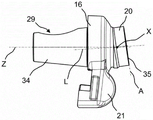
FIG. 5 shows a perspective side view of the tool changer seat;
figure 6 shows a cross-sectional view of a tool holder with a milling chisel according to the prior art;
FIG. 7 shows a cross-sectional view of a prior art tool changer base;
FIG. 8 shows a perspective side view of a prior art tool changer seat;
fig. 9 shows a sectional view of a first embodiment of a tool holder with a milling chisel;
FIG. 10 shows a cross-sectional view of a first embodiment of a tool changer base;
FIG. 11 shows a perspective side view of a first embodiment of a tool changer base;
fig. 12 shows a sectional view of a second embodiment of a tool changer with a milling chisel;
FIG. 13 shows a cross-sectional view of a second embodiment of a changer seat;
FIG. 14 shows a perspective side view of a second embodiment of the tool changer seat;
fig. 15 shows a prior art milling chisel at the moment of ground contact; and
fig. 16 shows the milling chisel at the moment of ground contact.
Detailed Description
In the drawings, the same reference numerals denote the same elements unless otherwise specified.
Fig. 1 shows a road milling machine 1, in particular a cold milling machine of the center-suspension type. The invention can also be applied to rear-mounted road milling machines. The road milling machine 1 comprises a machine frame 3 with a driver's cab 2. The frame 3 is carried by a running gear 6, which in the embodiment shown is a crawler, but may also be a wheel. Furthermore, the road milling machine 1 has a milling roller 9 which is mounted in a milling roller box 7 so as to be rotatable about a roller axis of rotation 10 which extends horizontally and transversely to the working direction a. The road milling machine 1 is designed to be self-propelled and has a drive motor 4 which provides the drive energy required for operating the road milling machine 1. The drive motor 4 is typically an internal combustion engine, for example a diesel engine. Alternatively, the drive motor may also be an electric motor. In working operation, the road milling machine 1 is moved in a working direction a over the ground 8 and mills the ground. The loosened ground material is transported out of the milling roller box 7 and loaded onto the transport device 5. The conveyor 5 in turn conveys the milled material to a transport vehicle, not shown, for example a truck, which then transports the milled material away. The chassis 6 can be height-adjustable relative to the machine frame 6, in part or in whole, by means of a lifting device, usually a so-called lifting column, in order to be able to vary the milling depth, for example.
Fig. 2 shows a perspective side view of the milling roller 9. The milling roller has a substantially hollow-cylindrical roller tube 11, which can be connected to a drive train via a drive connection 17. A plurality of milling tools 39 are preferably arranged on the outer circumferential surface of the milling roller 9, which milling tools are also described in more detail below. On the illustrated end face of the milling roller 9, an end face side cutter 13 may be provided, which, during operation, cuts out free space in the ground 8 for milling the side face of the milling roller 9.
Fig. 3 shows an embodiment of a milling tool 39. Milling tool 39 preferably includes tool changing seat system 14 having base 15 and tool changing seat 16. A milling chisel 17 is preferably mounted on or in the tool changer 16. Fig. 4 shows a cross section of the milling cutter 39 according to fig. 3. Fig. 5 again shows a perspective view of the tool changer base 16 in isolation. The base 15 preferably has fastening feet 18, via which the base 15 can be fastened to the outer circumferential surface 38 of the roller tube 11. The base 15 preferably also comprises a tool changer receptacle 19, in which a tool changer receptacle 33 can be arranged. The tool holder receptacle 33 is preferably formed complementarily to the tool holder cone 34 formed by the tool holder body 20 of the tool holder 16. The tool changer base 16 is preferably supported in the mounted state in the tool changer base receptacle 33 by means of a tool changer base cone 34 and is supported in such a way that the circumferential surface K of the tool changer base cone 34 rests against the inner surface of the tool changer base receptacle 33, preferably at least partially around the cone axis 7. In order to fix the tool changer base 16 on the base 15, a tensioning device 25 with a tensioning element 36, for example a screw, is preferably provided. The tension element 36 preferably extends through the base and all the way into the tool holder receptacle 33. The tool changer cone 34 is in turn preferably provided with a tension member support structure 37, for example a bore with an internal thread, which may be configured for receiving the tension member 36. In general, the tension device 25 of the tool changing base 16 and in particular the tension element support 27 is preferably designed such that the tension force exerted by the tension element 36 on the tool changing base 16 acts along the cone axis Z. In particular, the circumferential surface K of the tool holder cone 34 is pressed against the inner surface of the tool holder receptacle 33 of the base 15 by the tension of the tension element 36. In this way, the forces acting on the milling chisel 17 and the tool changing seat 16 during operation of the milling roller 9 can be efficiently transmitted to the base 15 and thus also to the roller tube 11 of the milling roller 9. Furthermore, this form of force transmission between tool holder 16 and base 15 through tool holder cone 34 is a typical feature of tool holder system 14 with tool holder cone 34 and distinguishes it from other tool holder systems.
Further, it is preferable to provide the holder accommodating portion 30 in the tool changing base body 20. The shank receptacle 30 is in particular a cylindrical cavity which is formed complementarily to the shank 31 of the milling chisel 17. The shank receiving means preferably has a longitudinal center axis L which corresponds in particular to the axis of rotation of the cylindrical cavity and, in the mounted state of the milling chisel 17, also to the axis of rotation of the milling chisel 17. The axis of rotation of the milling chisel 17 preferably corresponds here both to the axis of rotation of the rotationally symmetrical arrangement of the milling chisel 17, which is in particular designed as a round shank chisel, and to the axis of rotation about which the milling chisel 17 can be rotated during operation of the milling roller 9. The shank receptacle 30 is preferably arranged along the cone axis Z and in particular lies on the cone axis Z. The shank holder is preferably designed to hold a shank 31 and a clamping sleeve 32, the clamping sleeve 32 at least partially surrounding the shank 31 and positively preventing an axial displacement of the milling chisel 17 and thus preventing the milling chisel from being pulled out or falling out of the shank holder 30. The shank receptacle 30 is preferably at least partially surrounded by a support shoulder 35 on the side of the tool holder body 20 opposite the tension element support 37 or tool holder cone 34. The support shoulder 35 preferably surrounds the shank pocket 30 at least partially and in particular completely. Furthermore, the bearing shoulder 35 preferably forms a bearing surface in the bearing plane a. The bearing plane a is preferably arranged perpendicular to the longitudinal center axis L. The support shoulder 35 preferably serves as a seat for the wear plate 28, which rests on the support shoulder, which likewise preferably completely surrounds the shank receptacle 30 and rests with a rear seat on the cutting head 27 of the milling chisel 17. Milling chisel 17 comprises, in addition to a shank 31 and a cutting head 27, in particular a tip 26, which is usually made at least partially of hard metal. During operation of the road milling machine 1 or the milling roller 9, the milling chisel 17 is preferably rotatable about the longitudinal center axis L, which causes the milling chisel 17 to wear out uniformly.
Further, the tool holder body 20 preferably forms a base clamp 21. The base clip 21 preferably comprises a web region 22 and a clip arm 23. The web region 22 preferably comprises elevations oriented away from the gripper arm and the base or tool changing seat cone 34, which serve to crush the milled material pieces thrown up during the milling operation and to withstand the wear occurring in this case instead of the base 15. The holding arms 23 are in turn preferably formed complementary to the grooves 24 on the base 15 and engage in particular in said grooves 24. The clamping arm 23 preferably enables a force directed away from the milling roller 9 to be introduced from the tool changing seat 16 into the base 15 in a form-fitting manner. The gripping arm 23 and the described force transmission from tool changing seat 16 to base 15 are typical features of tool changing seat system 14 with tool changing seat cone 34.
Furthermore, the tool holder body 20 preferably has a top outlet 29. The top outlet 29 is preferably arranged on the side of the tool holder body 20 opposite the base grip 21 and in particular forms a cavity which extends from the outside of the tool holder body 20 as far as the tool holder receptacle 30 and is connected thereto. The rear end of the shank 31 is therefore preferably accessible from the outside through the top opening 29. In order to ensure this accessibility when tool magazine system 14 is completely installed, a corresponding ejection opening 29 is preferably likewise provided in base 15, which extends from the outside of base 15 into tool magazine receptacle 33 and is connected thereto. The ejection opening 29 in the base 15 is in particular configured such that it is connected to the ejection opening 29 in the tool holder 16 when the tool holder 16 is mounted in the base 15. Overall, therefore, the top outlet 29 preferably provides an open access to the rear end of the shank 31 of the milling chisel 17, starting from the outside of the tool changing seat system 14. Through the ejection opening 29, a tool can thus be introduced, which comes into contact with the tool shank 31, so that the tool shank can be ejected, for example, by targeted hammering.
Longitudinal central axis of shank pocket 30L is preferably at an angle W relative to the cone axis Z 3 And forming an oblique angle. Preferably, the longitudinal central axis L and the cone axis Z lie in a common plane, so that these axes intersect at an intersection point X. The point of intersection X is preferably arranged within the spatial extension of the knife holder 16. The point of intersection X is particularly preferably located in the cylindrical cavity of the shank receiving portion 30. The longitudinal center axis L is in particular at an angle W in a direction away from the base holding portion 21 with respect to the cone axis Z 3 And forming an oblique angle. This relates in particular to the section of the longitudinal center axis L remote from the tool changer cone 34 or the tension element bearing structure 37. In other words, in particular the half of the longitudinal center axis L which, starting from the tool holder cone 34 or the tension element bearing 37, is located behind the point X of intersection of the cone axis Z with the longitudinal center axis L is beveled away from the base grip 21. Conversely, the half of the longitudinal center axis L oriented in the direction of the tool holder cone 34 or the tension element support 37 can be inclined toward the base grip 21 by the oblique angle between the longitudinal center axis L and the cone axis Z. By means of a corresponding bevel, the nose 26 of the milling chisel 17 mounted on the tool changer 16 is preferably oriented in a direction away from the milling roller 9 or from the outer circumferential surface 38 of the roller tube 11. That is to say, the longitudinal center axis L and also the milling chisel 17 are preferably steeper with respect to the outer circumferential surface 38 by means of the bevel, which brings about the advantages already described during the film milling.
As shown in FIG. 4, the angle W between the cone axis Z and the outer peripheral surface 38 of the roller tube 11 4 Preferably smaller than the angle W between the longitudinal mid-axis L and the outer circumferential surface 38 of the roller tube 11 5 . Angle W 4 、W 5 The difference between these corresponds in particular to the oblique angle between the longitudinal mid-axis L and the cone axis Z. In the embodiment shown in FIG. 4, angle W 3 For example, 8 deg., angle W 4 For example 44 deg., and an angle W 5 For example 52. As already explained, the bearing plane a of the bearing shoulder 35 is preferably arranged perpendicular to the longitudinal center axis L. This results in that the bearing plane a is preferably not oriented perpendicular to the cone axis Z. Angle W between support plane a and cone axis Z 6 Preferably an angle unequal to 90 deg.. The angle W 6 For example 90 ° plus the angle W between the longitudinal mid-axis L and the cone axis Z 3 In the embodiment shown in fig. 4 because it is, for example, 98.
As can also be seen in particular from fig. 4, the longitudinal center axis L preferably does not intersect the circumferential surface K of the tool holder cone 34. In particular, the longitudinal central axis L preferably passes through the circumferential surface K of the truncated cone forming the tool holder cone 34, but preferably only through the lower surface of the truncated cone and its top surface, but not through the circumferential surface K. However, if an extrapolation extension K 'of the circumferential surface K is considered, which is outside the actual surface of the tool holder cone 34, it is preferred that the longitudinal center axis L intersects the extrapolation extension K' of the circumferential surface K at an intersection point Y. The point of intersection Y is preferably also located within the spatial extension of the base 15. In addition or alternatively, it can be provided that the intersection point Y is a point of the extrapolated extension K' of the circumferential surface K which is closest to the outer circumferential surface 38 of the roller tube 11 in a section perpendicular to the cone axis Z.
Fig. 6 to 14 show a comparison of the prior art (fig. 6 to 8) with the first embodiment (fig. 9 to 11) and the second embodiment (fig. 12 to 14) of the invention with a transverse section of the tool holder 16 with a milling chisel 17 (fig. 6, 9 and 12), a transverse section of the tool holder 16 alone (fig. 7, 10 and 13) and a side view of the tool holder 16 (fig. 8, 11 and 14), respectively. Fig. 6 to 8 show the prior art as also explained in detail in EP 2 425 951 A1. In the prior art, the longitudinal mid-axis L and the cone axis Z are parallel and coaxial with each other, i.e. the two axes are identical/coincide. In other words, the longitudinal mid-axis L and the cone axis Z have an infinite number of intersection points. In contrast, in the embodiment of the invention according to fig. 9 to 14, the longitudinal mid-axis L and the cone axis Z are not identical but are at an oblique angle to each other. However, the two axes preferably lie in the same plane, so that the two axes in particular have exactly one point of intersection X. In the embodiment according to fig. 9-11, the angle W between the longitudinal mid-axis L and the cone axis Z 3 For example 4 deg., whereas in the embodiment according to fig. 12-14 this angle is for example 8 deg..
As can be derived in particular from the comparison of fig. 6 to 8 with the exemplary embodiments of the invention according to fig. 9 to 14 for the prior art, it is preferred that only the modifications to the prior art are madeThe orientation of the tool holder cone 34 and the support shoulder 35, which are each inclined by an angle W, is changed 3 . In particular, all shapes and surfaces of the tool changer base 16 that come into contact with the base 15 in the mounted state of the tool changer system 14 are unchanged from the prior art, so that the same base 15 as known from the prior art can likewise be used in combination with the tool changer base 16 according to the invention. Thus, no special base 15 has to be manufactured or mounted on milling roller 9 in order to use the tool changing seat according to the invention. This results in a reduction of the manufacturing and use costs of the system according to the invention. Furthermore, the tool changer 16 according to the invention can be retrofitted particularly easily to an already existing milling roller 9 by simply fixing it in a conventional manner to an already existing base 15. Thus, the existing milling roller 9 can also be quickly and easily retrofitted for the thin-film milling operation to be carried out.
Fig. 15 and 16 show a comparison of a milling cutter 39 according to the prior art (fig. 15) with a milling cutter 39 according to the invention (fig. 16) in a working operation of the milling roller 9. Fig. 15 and 16 show in particular the moment when the milling chisel 17 comes into contact with the ground 8 to be milled in the working operation. For this purpose, the milling roller 9 is rotated about a roller rotation axis 10. The path of the nose 26 of the milling chisel 17 through this rotary movement is designated as the cutting circle S. An angle W exists between the longitudinal mid-axis L and a line R extending perpendicularly from the roll rotation axis 10 and through the cutting edge 26 1 . That is, the straight line R is drawn radially from the roller rotation axis 10 and intersects the nose 26. In the case of the prior art shown in FIG. 15, the angle W 1 Greater than in the case of the milling cutter 39 according to the invention shown in fig. 16. In the specifically illustrated example, the angle W 1 40 in fig. 15 and 32 in fig. 16. In the present invention, it is preferable that the angle W 1 Is 40 DEG minus the angle W between the longitudinal central axis L and the cone axis Z 3 . This results in a reduction of the angle W2 between the longitudinal mid-axis L and the vertical direction V in relation to the prior art. In the example shown, the angle W 2 24 on the left and 16 on the right. In the present inventionPreferably, the angle W 2 Is 24 DEG minus the angle W between the longitudinal central axis L and the cone axis Z 3 . As shown in fig. 15, it is thereby achieved that the milling chisel 17 is oriented more steeply relative to the ground 8 at the moment of contact with the ground than in the prior art. In particular in the case of thin-film milling, it is thereby achieved that the milling chisel and the tool holder are uniformly loaded, so that they have more uniform wear and overall a longer service life.
Claims (11)
1. Tool changing base (16) for a tool changing base system (14) for fastening a milling chisel (17), in particular rotationally symmetrical, on a milling roller (9) of a road milling machine (1), comprising:
-a tool holder body (20),
a shank receptacle (30) extending in the tool holder body (20) along the longitudinal center axis (L) for receiving a shank (31) of a milling chisel (17),
a tool holder cone (34) which is formed by the tool holder body (20) and is at least partially located in the extension of the shank receptacle (30), said tool holder cone being designed for clamping in an at least partially complementarily formed tool holder receptacle (33) of the base (15) of the tool holder system (14),
-a tension element support (37) arranged on the tool holder cone (34), which is designed for the insertion of a tension element (36), by means of which the tool holder cone (34) can be clamped to the base (15) in the direction of the cone axis (Z) of the tool holder cone (34),
it is characterized in that the preparation method is characterized in that,
the shank receptacle (30) and the tension element support (37) are designed in such a way that the longitudinal center axis (L) and the cone axis (Z) lie in a common plane and are at an oblique angle to one another in this common plane.
2. The tool changing holder (16) according to claim 1, characterized in that the longitudinal mid-axis (L) and the cone axis (Z) mutually form an oblique angle of at least 3 °, preferably at least 5 °, in particular at least 8 ° and ideally at least 10 °.
3. The tool changer base (16) according to one of the preceding claims, characterized in that it is configured such that the longitudinal mid-axis (L) intersects the cone axis (Z) at an intersection point (X) and that the intersection point (X) is located in the tool changer base (16), in particular in the shank pocket (30).
4. Tool holder (16) according to one of the preceding claims, characterized in that the longitudinal mid-axis (L) intersects the circumference (K) of the tool holder cone (34) and/or an outwardly extending extension (K') of the circumference (K) of the tool holder cone (34) outside the circumference (K) at an intersection point (Y) without intersecting it.
5. Tool changing seat (16) according to one of the preceding claims, characterized in that the tool changing seat body (20) has a bearing shoulder (35) which at least partially surrounds an inlet opening of a shank pocket (30) and ends in a bearing plane (A), and the bearing plane (A) is arranged perpendicular to the longitudinal mid-axis (L) and/or at an angle (W) which differs from 90 ° 6 ) Intersecting the cone axis (Z).
6. Tool changing seat (16) according to one of the preceding claims, characterized in that the tool changing seat body (20) comprises a basic clamping portion (21) with a clamping arm (23) configured for embedding in a groove (24) on the base (15), and in that the longitudinal centre axis (L) is at an oblique angle relative to the cone axis (Z) in a direction away from the basic clamping portion (21), in particular away from the clamping arm (23).
7. Tool changing seat system (14) for fixing a milling chisel (17) on a milling roller (9) of a road milling machine (1), in particular with a milling chisel (17), comprising a base (15) and a tool changing seat (16) according to one of the preceding claims.
8. Milling roller (9) for a road milling machine (1), the milling roller (9) being configured for rotation about a roller rotation axis (10) and comprising a tool magazine system (14) fixed on the milling roller (9) according to claim 7 and a milling chisel (17) having a tip (26) fixed on the tool magazine system.
9. Milling roller (9) according to claim 8, characterized in that the angle (W) between the longitudinal center axis (L) of the shank receptacle (30) and a straight line (8) running perpendicularly from the roller axis of rotation (10) and extending through the cutting tip (26) 1 ) Maximum 37 °, preferably maximum 35 °, particularly preferably maximum 32 °, and ideally maximum 30 °.
10. Milling roller (9) according to one of claims 8 to 9, characterised in that the angle (W) between the longitudinal mid-axis (L) and the outer circumferential surface (38) of the milling roller (9) 5 ) Is greater than the angle (W) between the cone axis (Z) and the outer circumferential surface (38) of the milling roller (9) 4 )。
11. Road milling machine, characterized in that it comprises a milling roller according to any one of claims 8 to 10.
Applications Claiming Priority (2)
| Application Number | Priority Date | Filing Date | Title |
|---|---|---|---|
| DE102021112757.2A DE102021112757A1 (en) | 2021-05-17 | 2021-05-17 | CHANGE HOLDER, BITS CHANGE HOLDER SYSTEM, MILLING DRUM FOR A ROAD MILLING MACHINE AND ROAD MILLING MACHINE |
| DE102021112757.2 | 2021-05-17 |
Publications (1)
| Publication Number | Publication Date |
|---|---|
| CN115369727A true CN115369727A (en) | 2022-11-22 |
Family
ID=80928568
Family Applications (1)
| Application Number | Title | Priority Date | Filing Date |
|---|---|---|---|
| CN202210510218.6A Pending CN115369727A (en) | 2021-05-17 | 2022-05-10 | Tool changing seat, tool changing seat system, milling and planing roller for road milling and planing machine and road milling and planing machine |
Country Status (4)
| Country | Link |
|---|---|
| US (1) | US20220364318A1 (en) |
| EP (1) | EP4092192B1 (en) |
| CN (1) | CN115369727A (en) |
| DE (1) | DE102021112757A1 (en) |
Families Citing this family (2)
| Publication number | Priority date | Publication date | Assignee | Title |
|---|---|---|---|---|
| DE102024112597A1 (en) * | 2024-05-06 | 2025-11-06 | Wirtgen Gmbh | Chisel holder |
| DE102024112600A1 (en) * | 2024-05-06 | 2025-11-06 | Wirtgen Gmbh | Chisel holder |
Citations (7)
| Publication number | Priority date | Publication date | Assignee | Title |
|---|---|---|---|---|
| US4337980A (en) * | 1979-05-21 | 1982-07-06 | The Cincinnati Mine Machinery Company | Wedge arrangements and related means for mounting means, base members, and bits, and combinations thereof, for mining, road working, or earth moving machinery |
| DE3630443A1 (en) * | 1986-09-06 | 1988-03-10 | Worley & Partner Gmbh | Device for the cutting winning/extraction of materials |
| EP1033216A1 (en) * | 1999-03-03 | 2000-09-06 | BITELLI S.p.A. | Toolholder for milling drums for removing ground |
| US20120068527A1 (en) * | 2010-09-07 | 2012-03-22 | Bomag Gmbh | Quick-change tool holder system for a cutting tool |
| US20160003041A1 (en) * | 2014-07-03 | 2016-01-07 | Sandvik Intellectual Property Ab | Variable Angle Cutting Bit Retaining Assembly |
| CN109629383A (en) * | 2017-10-09 | 2019-04-16 | 维特根有限公司 | Chisel holder |
| CN211227999U (en) * | 2019-07-30 | 2020-08-11 | 苏州五元素机械制造有限公司 | Knife rest |
Family Cites Families (13)
| Publication number | Priority date | Publication date | Assignee | Title |
|---|---|---|---|---|
| GB1138531A (en) * | 1965-04-02 | 1969-01-01 | Coal Industry Patents Ltd | Mining ploughs and cutter tool-mounting adaptors for use in such ploughs |
| DE19908656C1 (en) | 1999-02-27 | 2000-08-31 | Wirtgen Gmbh | Chisel holder changing system |
| US8523289B2 (en) * | 2009-04-10 | 2013-09-03 | Kennametal Inc. | Retention assembly for cutting bit |
| DE102009052351A1 (en) | 2009-11-07 | 2011-05-12 | Michael Steinbrecher | milling drum |
| DE102010051048A1 (en) | 2010-11-11 | 2012-05-16 | Bomag Gmbh | Change-holder system for a chisel |
| TWI468253B (en) * | 2010-12-03 | 2015-01-11 | Wirtgen Gmbh | Chisel holder and chisel holder system with a chisel holder and a base |
| AU2011334838B2 (en) | 2010-12-03 | 2016-05-19 | Wirtgen Gmbh | Chisel holder |
| DE102012022879B4 (en) | 2012-08-24 | 2015-10-01 | Bomag Gmbh | Construction machine with a dust extraction device, device for dust extraction for a construction machine and method for extracting dust from a construction machine |
| DE102013002639C5 (en) | 2013-02-15 | 2022-06-30 | Bomag Gmbh | Ground milling machine, in particular road milling machine and method for moving a safety bar of such a ground milling machine |
| DE102014011878B4 (en) | 2014-08-11 | 2021-04-01 | Bomag Gmbh | Ground milling machine, method of dismantling and method of installing a milling device |
| DE102014016500A1 (en) * | 2014-11-07 | 2016-05-12 | Bomag Gmbh | Tool device for a ground milling machine and ground milling machine with such a tool device |
| DE102016224606B4 (en) | 2016-12-09 | 2021-01-07 | Wirtgen Gmbh | Device for the machining of wear-loaded bit holders of road milling machines and use of a device for the repair of such wear-loaded bit holders |
| CN110983927B (en) * | 2019-12-17 | 2024-12-31 | 江苏五元素机械制造有限公司 | Cutting device with fastening member |
-
2021
- 2021-05-17 DE DE102021112757.2A patent/DE102021112757A1/en active Pending
-
2022
- 2022-03-19 EP EP22163116.1A patent/EP4092192B1/en active Active
- 2022-04-28 US US17/661,099 patent/US20220364318A1/en not_active Abandoned
- 2022-05-10 CN CN202210510218.6A patent/CN115369727A/en active Pending
Patent Citations (7)
| Publication number | Priority date | Publication date | Assignee | Title |
|---|---|---|---|---|
| US4337980A (en) * | 1979-05-21 | 1982-07-06 | The Cincinnati Mine Machinery Company | Wedge arrangements and related means for mounting means, base members, and bits, and combinations thereof, for mining, road working, or earth moving machinery |
| DE3630443A1 (en) * | 1986-09-06 | 1988-03-10 | Worley & Partner Gmbh | Device for the cutting winning/extraction of materials |
| EP1033216A1 (en) * | 1999-03-03 | 2000-09-06 | BITELLI S.p.A. | Toolholder for milling drums for removing ground |
| US20120068527A1 (en) * | 2010-09-07 | 2012-03-22 | Bomag Gmbh | Quick-change tool holder system for a cutting tool |
| US20160003041A1 (en) * | 2014-07-03 | 2016-01-07 | Sandvik Intellectual Property Ab | Variable Angle Cutting Bit Retaining Assembly |
| CN109629383A (en) * | 2017-10-09 | 2019-04-16 | 维特根有限公司 | Chisel holder |
| CN211227999U (en) * | 2019-07-30 | 2020-08-11 | 苏州五元素机械制造有限公司 | Knife rest |
Also Published As
| Publication number | Publication date |
|---|---|
| DE102021112757A1 (en) | 2022-11-17 |
| EP4092192A1 (en) | 2022-11-23 |
| US20220364318A1 (en) | 2022-11-17 |
| EP4092192B1 (en) | 2024-01-10 |
Similar Documents
| Publication | Publication Date | Title |
|---|---|---|
| US8534766B2 (en) | Indexable cutting tool system | |
| EP0860552B1 (en) | Apparatus for roadway surface reclaiming drum | |
| CN1816432B (en) | Construction machinery | |
| US7743803B2 (en) | Stump grinding wheel | |
| CA2763998C (en) | Bit holding system with an opening for removal of broken bits | |
| EP1123173B2 (en) | Anti-rotation mounting mechanism for round cutting insert | |
| CN101666229B (en) | Tool rest | |
| WO2014022331A1 (en) | Milling drum having integral tool mounting blocks | |
| EP2359965B1 (en) | A turning insert, a tool part, a method as well as a machine tool for chip-cutting metal machining | |
| CN107002373B (en) | Cutter arrangement for a ground milling machine and ground milling machine having such a cutter arrangement | |
| CN102971492A (en) | Cutter assembly configured to allow tool rotation | |
| US20220364318A1 (en) | Quick-change holder, quick-change chisel holder system, milling roller for a road milling machine, and road milling machine | |
| CN104508207B (en) | Milling roller knife rest | |
| US8770669B2 (en) | Cutting tool configuration having wear disc | |
| US10968577B2 (en) | Tool combination having a chisel holder and two chisels | |
| US6835114B2 (en) | Grinding tool for buttons of a rock drill bit | |
| CN105525562B (en) | Milling roller and ground milling machine with such a milling roller | |
| AU2001254560A1 (en) | Grinding tool for buttons of a rock drill bit | |
| CA2488627C (en) | Stump grinding apparatus having a rotatable toothed disc | |
| US10184336B2 (en) | Milling tool holder | |
| US10968740B2 (en) | Interchangeable chisel holder | |
| CN108779611A (en) | Locking system for preventing cutter holder from rotating | |
| US20220410342A1 (en) | Improved control system for grinding apparatus | |
| US20240384653A1 (en) | Non-rotating bit for cutting tool | |
| US20240383051A1 (en) | Non-rotating bit for cutting tool |
Legal Events
| Date | Code | Title | Description |
|---|---|---|---|
| PB01 | Publication | ||
| PB01 | Publication | ||
| SE01 | Entry into force of request for substantive examination | ||
| SE01 | Entry into force of request for substantive examination | ||
| WD01 | Invention patent application deemed withdrawn after publication | ||
| WD01 | Invention patent application deemed withdrawn after publication |
Application publication date: 20221122 |