CN115427770A - Sensor device with alignment device - Google Patents
Sensor device with alignment device Download PDFInfo
- Publication number
- CN115427770A CN115427770A CN202080099837.XA CN202080099837A CN115427770A CN 115427770 A CN115427770 A CN 115427770A CN 202080099837 A CN202080099837 A CN 202080099837A CN 115427770 A CN115427770 A CN 115427770A
- Authority
- CN
- China
- Prior art keywords
- sensor
- housing
- sensor device
- container
- antenna
- Prior art date
- Legal status (The legal status is an assumption and is not a legal conclusion. Google has not performed a legal analysis and makes no representation as to the accuracy of the status listed.)
- Pending
Links
Images


Classifications
-
- H—ELECTRICITY
- H01—ELECTRIC ELEMENTS
- H01Q—ANTENNAS, i.e. RADIO AERIALS
- H01Q1/00—Details of, or arrangements associated with, antennas
- H01Q1/12—Supports; Mounting means
- H01Q1/22—Supports; Mounting means by structural association with other equipment or articles
- H01Q1/225—Supports; Mounting means by structural association with other equipment or articles used in level-measurement devices, e.g. for level gauge measurement
-
- G—PHYSICS
- G01—MEASURING; TESTING
- G01F—MEASURING VOLUME, VOLUME FLOW, MASS FLOW OR LIQUID LEVEL; METERING BY VOLUME
- G01F23/00—Indicating or measuring liquid level or level of fluent solid material, e.g. indicating in terms of volume or indicating by means of an alarm
- G01F23/22—Indicating or measuring liquid level or level of fluent solid material, e.g. indicating in terms of volume or indicating by means of an alarm by measuring physical variables, other than linear dimensions, pressure or weight, dependent on the level to be measured, e.g. by difference of heat transfer of steam or water
- G01F23/28—Indicating or measuring liquid level or level of fluent solid material, e.g. indicating in terms of volume or indicating by means of an alarm by measuring physical variables, other than linear dimensions, pressure or weight, dependent on the level to be measured, e.g. by difference of heat transfer of steam or water by measuring the variations of parameters of electromagnetic or acoustic waves applied directly to the liquid or fluent solid material
- G01F23/284—Electromagnetic waves
Landscapes
- Physics & Mathematics (AREA)
- Electromagnetism (AREA)
- Thermal Sciences (AREA)
- Fluid Mechanics (AREA)
- General Physics & Mathematics (AREA)
- Measurement Of Levels Of Liquids Or Fluent Solid Materials (AREA)
- Radar Systems Or Details Thereof (AREA)
Abstract
本发明涉及用于测量容器(20)中的填充材料或松散材料(25)的填充物位或极限物位的传感器装置(10)以及传感器装置的用于测量容器中的填充材料或松散材料的填充物位或极限物位的用途。传感器装置(10)包括具有天线(200)的传感器以及具有对准设备(101)的传感器壳体(100、100a、100b、100c),对准设备具有第一部分(110、110a、110b、110c)和被构造为容纳天线的第二部分(120、120a、120b、120c)。第一部分和第二部分被构造为能够相对彼此旋转。对准设备被构造为通过旋转第一部分和/或第二部分来改变传感器的测量信号(30)的辐射方向。
The invention relates to a sensor device (10) for measuring the filling level or limit level of filling material or bulk material (25) in a container (20) and to a sensor device for measuring filling material or loose material in a container Use of fill level or limit level. The sensor arrangement (10) comprises a sensor with an antenna (200) and a sensor housing (100, 100a, 100b, 100c) with an alignment device (101) having a first part (110, 110a, 110b, 110c) and a second portion (120, 120a, 120b, 120c) configured to receive the antenna. The first part and the second part are configured to be rotatable relative to each other. The alignment device is configured to change the radiation direction of the sensor's measurement signal (30) by rotating the first part and/or the second part.
Description
相关申请的交叉引用Cross References to Related Applications
本申请要求2020年4月15日提交的国际专利申请PCT/EP2020/060614和2020年4月15日提交的国际专利申请PCT/EP2020/060615的优先权,其全部内容通过引用并入本文。This application claims priority to International Patent Application PCT/EP2020/060614, filed April 15, 2020, and International Patent Application PCT/EP2020/060615, filed April 15, 2020, the entire contents of which are incorporated herein by reference.
技术领域technical field
本发明涉及在工业环境中使用的传感器装置。特别地,本发明涉及用于测量容器中的填充材料或松散材料的填充物位或极限物位的传感器装置、具有用于在容器上安装和对准传感器装置的对准设备的传感器壳体、传感器装置的用于测量容器中的填充材料或松散材料的填充物位或极限物位的用途以及具有对准设备的传感器壳体的用于在容器上安装和对准传感器装置的用途。The invention relates to sensor devices for use in industrial environments. In particular, the invention relates to a sensor device for measuring the filling level or limit level of filling material or bulk material in a container, a sensor housing with an alignment device for mounting and aligning the sensor device on the container, The use of a sensor device for measuring the filling level or limit level of filling material or bulk material in a container and the use of a sensor housing with an alignment device for mounting and aligning the sensor device on a container.
背景技术Background technique
在工业环境中,通常将测量传感器例如用于填充物位测量、极限物位测量、流量测量、压力测量、液位或流速测量或者温度测量。尤其在过程系统中的容器(例如,GFK(Glasfaser-
发明内容Contents of the invention
本发明的目的是给出一种用于过程系统中的各种过程容器的具有灵活使用性和高可靠性的测量传感器。The object of the present invention is to provide a flexible and highly reliable measuring sensor for various process vessels in a process system.
该目的通过独立权利要求的特征来实现。本发明的改进示例在从属权利要求和以下说明中得出。This object is achieved by the features of the independent claims. Improved examples of the invention emerge from the dependent claims and the following description.
本公开的一方面涉及一种用于测量容器中的填充材料或松散材料的填充物位或极限物位的传感器装置。传感器装置包括具有天线的传感器、具有对准设备的传感器壳体。传感器壳体的对准设备包括第一部分和第二部分,第二部分被构造为容纳天线。第一部分和第二部分被设计为能够相对彼此旋转。对准设备被构造为通过旋转第一部分和/或第二部分来改变传感器的测量信号的辐射方向。An aspect of the disclosure relates to a sensor device for measuring a filling level or a limit level of filling material or bulk material in a container. The sensor arrangement comprises a sensor with an antenna, a sensor housing with an alignment device. The alignment device for the sensor housing includes a first portion and a second portion, the second portion being configured to accommodate the antenna. The first part and the second part are designed to be able to rotate relative to each other. The alignment device is configured to change the radiation direction of the measurement signal of the sensor by rotating the first part and/or the second part.
传感器装置的传感器可以是雷达传感器并且被构造为用于发射和接收电磁测量信号或测量波束的非接触式测量传感器。The sensor of the sensor device can be a radar sensor and is designed as a non-contact measuring sensor for emitting and receiving electromagnetic measuring signals or measuring beams.
即使容器顶部被设计为倾斜的、部分倾斜的(例如,圆锥形或碟形的),传感器装置也能够安装或布置在过程容器的外侧或容器顶部的外侧。当安装在倾斜的容器顶部时,传感器可以垂直向下对准或朝向容器中的填充材料或松散材料对准。例如,传感器可以被构造为穿过容器顶部测量填充物位或极限物位。Even if the vessel top is designed to be inclined, partially inclined (eg conical or dish-shaped), the sensor device can be mounted or arranged on the outside of the process vessel or on the outside of the vessel top. When mounted on top of a sloped vessel, the sensor can be aimed vertically down or towards the fill or loose material in the vessel. For example, the sensor can be configured to measure the fill level or limit level through the top of the container.
第一部分和第二部分可以形成对准设备,使得对准设备的第一部分和第二部分可以相对彼此旋转或枢转,从而能够改变由第二部分容纳的天线的方向。The first part and the second part may form the alignment device, such that the first part and the second part of the alignment device may be rotated or pivoted relative to each other, thereby being able to change the orientation of the antenna housed by the second part.
传感器壳体的第一部分可以布置在传感器壳体的第二部分的下方。因此,在每种情况下,可以将第一部分设计为传感器壳体的下部,并将第二部分设计为传感器壳体的上部。第一部分和第二部分可以直接或间接地连接。The first part of the sensor housing may be arranged below the second part of the sensor housing. It is therefore possible in each case to design the first part as the lower part of the sensor housing and the second part as the upper part of the sensor housing. The first part and the second part may be connected directly or indirectly.
此外,第一部分可以紧邻容器安装或安装在容器顶部的外侧上。因此,第二部分可以经由第一部分安装在容器上,并且传感器装置可以通过下侧的第一部分固定在容器上。Furthermore, the first part may be mounted next to the container or on the outside of the top of the container. Thus, the second part can be mounted on the container via the first part and the sensor arrangement can be fixed on the container via the first part on the underside.
容器可以是塑料容器或GFK容器。The container can be a plastic container or a GFK container.
例如,可以通过传感器壳体或对准设备将传感器粘合到容器的外侧,以便测量容器中的填充材料或松散材料。粘合安装可以有利地实现测量传感器的简单且快速的插入。可以优化传感器装置,使得总能够穿过容器和/或传感器壳体的具有相同材料厚度的相同材料发射测量信号或测量波束,并且该测量信号或测量波束不能因此偏转或变形。由此可以通过传感器装置进行可靠的测量。For example, the sensor can be bonded to the outside of the container via the sensor housing or alignment device in order to measure filled or loose material in the container. Adhesive mounting advantageously enables simple and rapid insertion of the measuring sensor. The sensor arrangement can be optimized such that a measurement signal or a measurement beam can always be emitted through the same material with the same material thickness of the container and/or sensor housing and cannot be deflected or deformed thereby. Reliable measurements can thus be carried out by the sensor system.
有利的是,通过传感器壳体的第一部分和第二部分的可旋转性,即使安装在倾斜的容器顶部上,天线或测量信号也可以在特定方向上对准填充材料,例如可以在垂直方向上或以垂直于填充材料的表面的方式对准。可以手动或自动地控制旋转。Advantageously, through the rotatability of the first part and the second part of the sensor housing, the antenna or the measuring signal can be directed at the filling material in a specific direction, for example vertically, even when mounted on an inclined container roof or aligned perpendicular to the surface of the filling material. Rotation can be controlled manually or automatically.
通过对准设备改变天线的对准和测量信号的辐射方向,即使在倾斜安装的情况下,也可以有利地使测量信号不受干扰或不受阻碍,从而确保容器中的填充材料或松散材料的可靠的填充物位确定、极限物位确定或拓扑确定。By changing the alignment of the antenna and the radiation direction of the measurement signal by means of the alignment device, it is advantageously possible to keep the measurement signal undisturbed or unhindered even in the case of an inclined installation, thus ensuring the safety of the filling material or loose material in the container Reliable fill level determination, limit level determination or topology determination.
可以相对于下表面改变辐射方向。作为辐射方向的替代或补充方案,也可以通过旋转改变安装方向或安装角度。The radiation direction can be changed relative to the lower surface. As an alternative or in addition to the radiation direction, it is also possible to change the installation direction or the installation angle by rotation.
雷达传感器可被设计为用于工业环境中的过程自动化。该雷达传感器可以在农业中使用,以例如监测移动饮用水容器或供给容器。例如,雷达传感器可用于工厂自动化领域或建筑自动化。Radar sensors can be designed for process automation in industrial environments. The radar sensor can be used in agriculture, for example to monitor mobile drinking water containers or supply containers. For example, radar sensors can be used in the field of factory automation or in building automation.
替代地或补充地,雷达传感器可用于私人家庭,例如在GFK燃油箱或雨水蓄水池上的经典安装。Alternatively or additionally, radar sensors can be used in private households, for example in the classic installation on GFK fuel tanks or rainwater cisterns.
术语“工业环境中的过程自动化”可以理解为技术的一个子领域,其包含无人工参与的操作机器和设备的所有措施。过程自动化的一个目标是在诸如化学、食品、制药、石油、造纸、水泥、航运或矿业之类的领域中使工厂的各个部件的交互自动化。为此,可以使用大量的传感器,这些传感器特别适用于过程工业的诸如机械稳定性、对于污染物的不敏感性、极端温度、极端压力之类的特定要求。通常将这些传感器的测量值传送到控制室,在控制室中可以监测诸如物位、极限物位、流量、压力或密度之类的过程参数,并且可以手动或自动更改整个工厂的设置。The term "process automation in an industrial environment" is to be understood as a subfield of technology which encompasses all measures for operating machines and plants without human intervention. One goal of process automation is to automate the interaction of various parts of a plant in fields such as chemistry, food, pharmaceuticals, petroleum, paper, cement, shipping or mining. For this purpose, a large number of sensors are available which are especially adapted to the specific requirements of the process industry such as mechanical stability, insensitivity to contamination, extreme temperatures, extreme pressures and the like. The measured values of these sensors are usually transmitted to a control room where process parameters such as level, limit level, flow, pressure or density can be monitored and settings can be changed manually or automatically throughout the plant.
工业环境中的过程自动化的一个子领域涉及工厂的物流自动化和供应链的物流自动化。在物流自动化领域中,借助于距离传感器和角度传感器使建筑物内或单个物流设备内的过程自动化。典型的应用是例如用于以下领域的物流自动化系统:机场的办理行李和货物托运处理领域、交通监控领域(收费系统)、贸易领域、包裹配送或还有建筑物安全(访问控制)领域。先前列出的示例的公共点在于,各个应用端都需要将存在检测与对象大小和位置的精确测量结合起来。为此,可以使用借助于激光、LED、2D相机或3D相机的基于光学测量方法的传感器,这些传感器根据渡越时间原理(ToF:time of flight)检测距离。A sub-field of process automation in an industrial environment concerns the automation of logistics in factories and the automation of logistics in supply chains. In the field of logistics automation, processes in buildings or in individual logistics plants are automated with the aid of distance and angle sensors. Typical applications are, for example, logistics automation systems for the areas of baggage and cargo consignment handling at airports, traffic monitoring (tolling systems), trade, parcel delivery or also building security (access control). Common to the previously listed examples is that each application needs to combine presence detection with precise measurement of object size and position. For this, sensors based on optical measuring methods by means of lasers, LEDs, 2D cameras or 3D cameras can be used, which detect distances according to the time-of-flight principle (ToF: time of flight).
工业环境中的过程自动化的另一子领域涉及工厂/制造自动化。在诸如汽车制造业、食品制造业、制药业或一般包装行业之类的许多行业中,都可以见到这种应用示例。工厂自动化的目的是使通过机器、生产线和/或机器人执行的货物生产自动化,即,在没有人工参与的情况下运行。在此使用的传感器以及在检测对象的位置和大小时对于测量精度的特定要求与上述物流自动化示例中的传感器和特定要求相当。Another subfield of process automation in industrial settings involves factory/manufacturing automation. Examples of such applications can be found in many industries such as the automotive industry, the food industry, the pharmaceutical industry or the packaging industry in general. The purpose of factory automation is to automate the production of goods performed by machines, production lines and/or robots, that is, to run without human involvement. The sensors used here and the specific requirements for measurement accuracy when detecting the position and size of objects are comparable to those in the logistics automation example above.
根据一实施例,第一部分包括第一腔室,并且第二部分包括第二腔室,天线布置在该第二腔室中。According to an embodiment, the first part comprises a first chamber and the second part comprises a second chamber in which the antenna is arranged.
第一腔室和第二腔室可以形成公共腔室。替代地,第一腔室和第二腔室可以分别形成为单独的封闭腔室。The first chamber and the second chamber may form a common chamber. Alternatively, the first chamber and the second chamber may be formed as separate closed chambers, respectively.
传感器的天线可以布置在第二部分的第二腔室中,并且被构造为通过第一部分或通过第一腔室穿过传感器壳体和/或容器顶部从传感器发射测量信号或测量波束,并接收从填充材料或松散材料反射的测量信号。An antenna of the sensor may be arranged in the second chamber of the second part and is configured to transmit a measurement signal or a measurement beam from the sensor through the first part or through the first chamber through the sensor housing and/or the container top and to receive Measurement signal reflected from filling material or loose material.
对准设备可被设计为使得传感器壳体的腔室具有高的保护度。例如,第一腔室和第二腔室可以在第一部分和第二部分内分别具有空气或是真空的,以便消除或至少最小化在测量信号穿过对准设备时测量信号的波束偏转对测量结果产生的影响。The alignment device can be designed such that the cavity of the sensor housing has a high degree of protection. For example, the first chamber and the second chamber may have air or vacuum in the first and second parts, respectively, in order to eliminate or at least minimize the effect of beam deflection of the measurement signal on the measurement signal as it passes through the alignment device. The impact of the result.
例如,传感器装置的天线可以是喇叭天线或抛物面天线或透镜天线。替代地,天线可以是阵列天线,传感器装置也可被构造为利用该阵列天线来检测填充材料或松散材料的拓扑结构。For example, the antenna of the sensor device may be a horn antenna or a parabolic antenna or a lens antenna. Alternatively, the antenna can be an array antenna, with which the sensor device can also be configured to detect the topology of the filling material or loose material.
传感器装置还可以包括例如具有电路板的电子设备,天线可以连接到该电子设备。电子设备可以包括电路板并且布置在对准设备或传感器壳体的第二部分的第二腔室中。The sensor arrangement may also comprise electronics, for example with a circuit board, to which the antenna may be connected. The electronics may include a circuit board and be disposed in the second cavity of the second portion of the alignment device or sensor housing.
根据另一实施例,天线偏心或居中地布置在传感器壳体的第二部分中。According to another embodiment, the antenna is arranged eccentrically or centrally in the second part of the sensor housing.
通过将天线偏心地布置在第二部分中,可以在安装到容器上之后通过使第一部分和/或第二部分相对彼此旋转来改变天线的高度或位置和/或来自天线的测量信号的方向。By arranging the antenna eccentrically in the second part, it is possible to change the height or position of the antenna and/or the direction of the measurement signal from the antenna after mounting on the container by rotating the first part and/or the second part relative to each other.
对于另一实施例,壳体的上侧可旋转部分可以具有显示器和/或按钮。因此,可以首先将传感器调节到测量任务(角度),并然后可以将显示器旋转到正确的位置,以便用户更好地读取。For another embodiment, the upper rotatable part of the housing may have a display and/or buttons. Thus, the sensor can first be adjusted to the measuring task (angle), and then the display can be rotated into the correct position for better reading by the user.
根据另一实施例,传感器装置还包括偏振设备,该偏振设备被构造为通过旋转第一部分和/或第二部分来改变测量信号的偏振。According to another embodiment, the sensor device further comprises a polarization device configured to change the polarization of the measurement signal by rotating the first part and/or the second part.
偏振设备可以设置在传感器壳体的第一部分中。替代地或补充地,偏振设备可以设置在第一部分和第二部分之间或在第一部分和容器顶部之间。A polarization device may be provided in the first part of the sensor housing. Alternatively or additionally, a polarizing device may be arranged between the first part and the second part or between the first part and the top of the container.
尤其当天线居中地布置在传感器壳体的第二部分中并且在安装之后不能或仅能通过旋转第一部分和/或第二部分来改变天线的对准或位置时,通过设置偏振设备,可以有利地通过改变偏振设备来改变传感器的测量信号的方向。By providing a polarization device, it can be advantageous especially when the antenna is arranged centrally in the second part of the sensor housing and the alignment or the position of the antenna cannot be changed or can only be changed by rotating the first part and/or the second part after mounting. ground by changing the polarization device to change the direction of the sensor's measurement signal.
根据另一实施例,传感器壳体是完全封闭的且/或不能以非破坏性的方式打开。According to another embodiment, the sensor housing is completely closed and/or cannot be opened in a non-destructive manner.
替代地,传感器壳体可以不是完全封闭的,并且可以例如在第一部分中具有开口,该开口在安装期间被容器顶部封闭。因此,测量波束可以仅穿过容器顶部进行辐射,从而可以进一步减少干扰。Alternatively, the sensor housing may not be completely closed and may, for example, have an opening in the first part which is closed by the container top during installation. As a result, the measurement beam can only radiate through the top of the vessel, which further reduces interference.
例如在室外应用中或在非常脏或多尘的环境中,封闭的传感器壳体可用于保护传感器装置的传感器或腔室免受污染或环境影响。For example in outdoor applications or in very dirty or dusty environments, a closed sensor housing can be used to protect the sensor or the chamber of the sensor device from contamination or environmental influences.
根据另一实施例,传感器被设计为自给式雷达传感器(AuRa传感器)。According to another embodiment, the sensor is designed as an autonomous radar sensor (AuRa sensor).
自给式显示设备是可从内部能源而不是以有线方式从外部能源中获取显示设备的操作所需的能量的显示设备。自给式雷达传感器可以具有例如原电池或蓄电池形式的内部电源。电源可以从外部以感应方式充电,或通过能量收集器进行无线充电。A self-contained display device is a display device that can obtain energy required for the operation of the display device from an internal power source rather than from an external power source in a wired manner. Self-contained radar sensors can have an internal power supply, for example in the form of primary cells or accumulators. The power supply can be charged inductively from the outside, or wirelessly via an energy harvester.
此外,雷达传感器可以具有无线电接口,该无线电接口被构造为将传感器检测或计算的雷达传感器数据无线地传输到诸如手机或服务器之类的外部接收器。Furthermore, the radar sensor may have a radio interface configured to wirelessly transmit radar sensor data detected or calculated by the sensor to an external receiver, such as a mobile phone or a server.
根据另一实施例,传感器装置还包括安装设备,该安装设备布置在第一部分和容器之间,并且被构造为通过第一部分将传感器装置安装到容器上。According to another embodiment, the sensor arrangement further comprises a mounting device arranged between the first part and the container and configured to mount the sensor device on the container via the first part.
通过安装设备,传感器装置例如可以通过粘合安装的方式进行安装。在此,粘合面可以设置在传感器壳体的下侧和容器顶部之间。替代地或补充地,安装设备可以具有安装板。By means of the mounting device, the sensor arrangement can be mounted, for example, by adhesive mounting. In this case, the adhesive surface can be arranged between the underside of the sensor housing and the top of the container. Alternatively or additionally, the mounting device can have a mounting plate.
替代地或补充地,安装设备可被设计为螺栓连接件或凸缘连接件。Alternatively or additionally, the mounting device can be designed as a screw connection or flange connection.
根据另一实施例,传感器装置包括吸收设备,该吸收设备由吸收材料制成并且布置在传感器壳体的第一部分中。According to another embodiment, the sensor device comprises an absorption device made of an absorption material and arranged in the first part of the sensor housing.
吸收材料可以安装在传感器壳体内或第一部分的内侧壁上,以便尤其当传感器倾斜布置时减少由塑料容器的第一反射引起的干涉反射。例如,通过安装在壳体中的吸收材料,可以吸收或衰减可能由传感器壳体的内部、粘合面或容器顶部或容器壁通过干涉反射而产生的测量信号的雷达能量。因此,可以避免或至少防止来自干扰反射的干扰信号返回到雷达传感器并因此影响测量结果。Absorbing material can be installed in the sensor housing or on the inner side wall of the first part in order to reduce interfering reflections caused by the first reflection of the plastic container, especially when the sensor is arranged obliquely. For example, radar energy of measurement signals which may be generated by interference reflections from the interior of the sensor housing, from adhesive surfaces or from the top of the container or from the walls of the container can be absorbed or attenuated by means of an absorbing material installed in the housing. As a result, it is possible to avoid, or at least prevent, interference signals from interfering reflections returning to the radar sensor and thus affecting the measurement results.
传感器装置可以在第一部分和第二部分之间或在第一部分和第二部分之间的过渡处具有密封件,以便密封第一腔室和/或第二腔室。The sensor device may have a seal between the first part and the second part or at the transition between the first part and the second part in order to seal the first chamber and/or the second chamber.
根据另一实施例,第一部分和第二部分分别为斜切的中空圆柱体的形式,并且被构造为一体地、圆柱形地形成对准设备的传感器壳体。传感器壳体具有布置在第一部分和第二部分之间的斜面,并且被设计为使得第一部分和第二部分可以经由该斜面相对彼此旋转。According to another embodiment, the first part and the second part are each in the form of a chamfered hollow cylinder and are configured integrally, cylindrically forming the sensor housing of the alignment device. The sensor housing has a slope arranged between the first part and the second part and is designed such that the first part and the second part can be rotated relative to each other via the slope.
在斜面处,第一部分连接到第二部分。当第一腔室和第二腔室形成传感器壳体的公共腔室时,可以虚拟地形成斜面。替代地,斜面可被设置为闭合腔室(即,第一腔室和第二腔室)之间的旋转面。At the ramp, the first part is connected to the second part. When the first chamber and the second chamber form a common chamber of the sensor housing, a slope may be virtually formed. Alternatively, the inclined plane may be provided as a plane of revolution between the closed chambers (ie the first chamber and the second chamber).
因此,对准设备可以通过可旋转的第一部分和第二部分具有第一旋转轴线。Thus, the alignment device may have a first axis of rotation through the rotatable first part and the second part.
根据另一实施例,传感器的天线被设计为突出到第一腔室中。According to another embodiment, the antenna of the sensor is designed to protrude into the first chamber.
在第一腔室和第二腔室形成传感器壳体的公共腔室的情况下,天线可以居中或偏心地安装在传感器壳体的第二部分的第二腔室中,并且也可以布置在第一腔室中,而不与第一部分的下侧接触。如果天线偏心地布置,则可以将天线安装到第二部分的壳体部分的较短部分处。因此,测量传感器可以紧邻容器布置。In case the first chamber and the second chamber form a common chamber of the sensor housing, the antenna can be mounted centrally or eccentrically in the second chamber of the second part of the sensor housing and can also be arranged in the second chamber of the sensor housing. a chamber without contacting the underside of the first part. If the antenna is arranged eccentrically, it is possible to mount the antenna at a shorter part of the housing part of the second part. Thus, the measuring sensor can be arranged in the immediate vicinity of the container.
根据一实施例,传感器壳体包括具有第三腔室的第三部分,该第三部分布置在第一部分和第二部分之间并被设计为能够分别相对于第一部分和/或第二部分旋转。According to an embodiment, the sensor housing comprises a third part with a third chamber, which is arranged between the first part and the second part and is designed to be rotatable relative to the first part and/or the second part, respectively .
根据另一实施例,第一部分和第三部分分别被设计为斜切的中空圆柱体,并且第二部分被设计为中空圆柱体。第一部分、第二部分和第三部分被构造为一体地、圆柱形地形成传感器壳体。According to another embodiment, the first part and the third part are each designed as a chamfered hollow cylinder and the second part is designed as a hollow cylinder. The first part, the second part and the third part are designed in one piece, cylindrically forming the sensor housing.
传感器壳体具有布置在第一部分和第三部分之间的斜面和布置在第二部分和第三部分之间的直面,斜面被设计为使得第一部分和第三部分可以通过斜面相对彼此旋转。The sensor housing has a slope arranged between the first part and the third part and a straight surface arranged between the second part and the third part, the slope is designed such that the first part and the third part can rotate relative to each other through the slope.
因此,传感器装置的对准设备可以具有两个旋转轴线和/或两个旋转面(即,斜面和直面)。因此,传感器装置可以具有更大的灵活性来改变测量信号的方向。Thus, the alignment device of the sensor arrangement may have two axes of rotation and/or two surfaces of rotation (ie a beveled surface and a straight surface). Thus, the sensor device can have greater flexibility to change the direction of the measurement signal.
传感器装置的对准设备可以具有多个旋转轴线和/或旋转面,这些旋转轴线和/或旋转面例如具有更小的旋转角。The alignment device of the sensor device can have several axes of rotation and/or surfaces of rotation, which have, for example, smaller angles of rotation.
传感器壳体可以一体地设计,使得第一腔室、第二腔室和第三腔室形成公共腔室,或者可以分别设计为封闭腔室。替代地,第一腔室和第三腔室可以形成公共腔室,并且其中天线安装到传感器壳体的第二腔室可被设计为封闭的腔室。The sensor housing can be designed integrally so that the first chamber, the second chamber and the third chamber form a common chamber, or can be designed as closed chambers respectively. Alternatively, the first chamber and the third chamber may form a common chamber, and the second chamber, in which the antenna is mounted to the sensor housing, may be designed as a closed chamber.
根据另一实施例,传感器的天线被设计在第二腔室中,并突出到第一腔室和/或第三腔室中。According to another embodiment, the antenna of the sensor is designed in the second chamber and protrudes into the first chamber and/or the third chamber.
仅在第一腔室、第二腔室和第三腔室形成公共腔室时,天线才能够突出到第一腔室和第三腔室中。The antenna can protrude into the first chamber and the third chamber only when the first chamber, the second chamber and the third chamber form a common chamber.
根据另一实施例,天线被设计为通过使第二部分相对于第三部分旋转并且使第三部分相对于第一部分旋转而布置在最高位置处。因此,天线可以紧邻容器顶部布置。According to another embodiment, the antenna is designed to be arranged at the highest position by rotating the second part relative to the third part and rotating the third part relative to the first part. Thus, the antenna can be placed immediately adjacent to the top of the container.
在倾斜安装的情况下,传感器装置可以例如通过粘合面安装到容器上。可以旋转传感器壳体的第三部分,使得具有传感器的第二部分可以水平放置,并且天线可以在预定的方向上对准以辐射测量信号。例如,可以旋转第二部分,直到天线可以位于所安装的传感器壳体的最高部分。In the case of an inclined installation, the sensor device can be attached to the container, for example, via an adhesive surface. The third part of the sensor housing can be rotated so that the second part with the sensor can be placed horizontally and the antenna can be aligned in a predetermined direction to radiate a measurement signal. For example, the second part can be rotated until the antenna can be located on the highest part of the mounted sensor housing.
根据另一实施例,第二部分被设计为能够与第一部分和第三部分分离。传感器壳体具有由第一部分和第三部分形成的第一壳体单元和由第二部分形成的第二壳体单元。According to another embodiment, the second part is designed to be separable from the first part and the third part. The sensor housing has a first housing unit formed from a first part and a third part and a second housing unit formed from a second part.
根据另一实施例,传感器装置还具有第二安装设备,该第二安装设备布置在第一壳体单元和第二壳体单元之间并且被构造为连接第一壳体单元和第二壳体单元。According to a further embodiment, the sensor device also has a second mounting device which is arranged between the first housing unit and the second housing unit and is designed to connect the first housing unit and the second housing unit unit.
如果将天线布置在第二部分的封闭的第二腔室中或第二壳体单元中,则第二壳体单元可以例如通过诸如胶带之类的安装设备安装到第一壳体单元上。因此,具有布置有传感器的天线的第二壳体单元可被设计为自给式雷达传感器,并且第二壳体单元可被设计为单独的对准设备或用于安装和对准传感器的适配器。If the antenna is arranged in the closed second chamber of the second part or in the second housing unit, the second housing unit can be mounted to the first housing unit, eg by means of a mounting device such as adhesive tape. Thus, the second housing unit with the antenna on which the sensor is arranged can be designed as a self-contained radar sensor, and the second housing unit can be designed as a separate alignment device or as an adapter for mounting and aligning the sensor.
根据一实施例,对准设备的第一部分为支架的形式,并且对准设备的第二部分为球体分段的形式。According to an embodiment, the first part of the alignment device is in the form of a bracket and the second part of the alignment device is in the form of a sphere segment.
替代地,第一部分可被设计为具有第一腔室的中空圆柱体的形式。Alternatively, the first part can be designed in the form of a hollow cylinder with the first chamber.
对准设备的第二部分可被设计为具有第二腔室的中空球体或球体分段或中空球体分段的形式,传感器或天线和/或电子设备布置在该第二腔室中。例如,中空球体分段可以是封闭的并且具有封闭的第二腔室。The second part of the alignment device may be designed in the form of a hollow sphere or a sphere segment or a hollow sphere segment with a second chamber in which the sensor or antenna and/or electronics are arranged. For example, the hollow sphere segment may be closed and have a closed second chamber.
中空球体分段可以是关节套(Gelenkpfanne)。The hollow spherical segment can be a joint sleeve.
第一部分和第二部分可以例如通过螺纹连接或卡扣连接以能够互旋转的方式连接。The first part and the second part may be connected in a mutually rotatable manner, for example by a screw connection or a snap connection.
根据另一实施例,传感器装置还具有密封元件,该密封元件被构造为密封传感器壳体。According to a further embodiment, the sensor device also has a sealing element which is designed to seal off the sensor housing.
例如,密封元件可以是O形密封件并且布置在传感器装置的球体区域中。For example, the sealing element can be an O-ring seal and be arranged in the area of the ball of the sensor device.
可以将诸如透镜之类的波束偏转设备设置在第二部分的下部中,以便例如使测量波束或测量信号偏转。A beam deflecting device, such as a lens, may be arranged in the lower part of the second part in order to deflect the measurement beam or the measurement signal, for example.
作为中空球形的第二部分的替代方案,第二部分可被设计为扁平的球体分段的形式。As an alternative to the hollow spherical second part, the second part can be designed in the form of flattened spherical segments.
根据一实施例,第一部分为支架的形式,并且传感器壳体的第二部分为扁平的球体分段的形式。According to an embodiment, the first part is in the form of a bracket and the second part of the sensor housing is in the form of a flattened spherical segment.
根据一实施例,第一部分为支撑设备的形式,并且传感器壳体的第二部分为中空圆柱体的形式。第二部分通过连接设备连接到第一部分。According to an embodiment, the first part is in the form of a support device and the second part of the sensor housing is in the form of a hollow cylinder. The second part is connected to the first part by a connecting device.
例如,连接设备可以是螺栓连接件。第一部分可被设计为底座或安装支架。因此,传感器可以例如通过安装支架连接到安装板。For example, the connecting device may be a bolted connection. The first part can be designed as a base or as a mounting bracket. Thus, the sensor can be connected to the mounting plate, eg by means of a mounting bracket.
根据另一实施例,传感器装置还包括第三部分,该第三部分具有橡胶套筒的形式并且布置在第一部分和第二部分之间。According to another embodiment, the sensor device further comprises a third part in the form of a rubber sleeve arranged between the first part and the second part.
橡胶套筒可以具有第三腔室并且被构造为密封和保护第二部分中的传感器与第一部分的支撑设备之间的空间。The rubber sleeve may have a third chamber and be configured to seal and protect a space between the sensor in the second part and the support device of the first part.
根据另一实施例,传感器装置还具有过滤器,该过滤器布置在传感器壳体的第一部分和/或第三部分上。According to a further embodiment, the sensor device also has a filter which is arranged on the first part and/or the third part of the sensor housing.
过滤器可以是压力补偿过滤器,并且可以作为上述实施例的第一腔室和/或第三腔室中的吸收设备的替代或补充方案进行设置。The filter may be a pressure compensating filter and may be provided as an alternative or in addition to the absorption device in the first and/or third chamber of the above described embodiments.
本公开的另一方面涉及一种具有对准设备的传感器壳体,该对准设备被构造为在容器上安装和对准传感器装置,以测量容器中的填充材料或松散材料的填充物位或极限物位。Another aspect of the present disclosure relates to a sensor housing having an alignment device configured to mount and align a sensor device on a container to measure the fill level or limit level.
本公开的另一方面涉及传感器装置的用于测量容器中的填充材料或松散材料的填充物位或极限物位的用途。Another aspect of the present disclosure relates to the use of a sensor device for measuring a filling level or a limit level of filling material or bulk material in a container.
本公开的另一方面涉及具有对准设备的传感器壳体的用于在容器上安装和对准传感器装置以测量容器中的填充材料或松散材料的填充物位或极限物位的用途。Another aspect of the present disclosure relates to the use of a sensor housing with an alignment device for mounting and aligning a sensor device on a container for measuring the filling level or limit level of filling or bulk material in the container.
下面将参考附图来说明本发明的其它实施例。如果在以下附图说明中使用了相同的附图标记,则它们表示相同或相似的元件。附图中的图示是示意性的,并且未按比例绘制。Other embodiments of the present invention will be described below with reference to the accompanying drawings. If the same reference numbers are used in the following description of the figures, they denote the same or similar elements. The illustrations in the figures are schematic and not drawn to scale.
附图说明Description of drawings
图1a示出了根据一实施例的传感器装置的测量构造的示意图。Fig. 1a shows a schematic diagram of a measurement configuration of a sensor device according to an embodiment.
图1b示出了根据一实施例的传感器装置的测量构造的示意图。Fig. 1 b shows a schematic diagram of a measurement configuration of a sensor device according to an embodiment.
图2示意性地示出了根据一实施例的传感器装置的传感器壳体的侧视图。Fig. 2 schematically shows a side view of a sensor housing of a sensor device according to an embodiment.
图3示意性地示出了根据一实施例的传感器装置的俯视图。Fig. 3 schematically shows a top view of a sensor device according to an embodiment.
图4a示出了根据一实施例的传感器装置的示意图。Fig. 4a shows a schematic diagram of a sensor device according to an embodiment.
图4b示出了根据另一实施例的传感器装置的示意图。Fig. 4b shows a schematic diagram of a sensor device according to another embodiment.
图4c示出了根据另一实施例的传感器装置的示意图。Fig. 4c shows a schematic diagram of a sensor device according to another embodiment.
图5a示出了根据一实施例的传感器装置的示意图。Fig. 5a shows a schematic diagram of a sensor device according to an embodiment.
图5b示出了根据另一实施例的传感器装置的示意图。Fig. 5b shows a schematic diagram of a sensor device according to another embodiment.
图5c示出了根据另一实施例的传感器装置的示意图。Fig. 5c shows a schematic diagram of a sensor device according to another embodiment.
图6a示出了根据一实施例的传感器装置的示意图。Fig. 6a shows a schematic diagram of a sensor device according to an embodiment.
图6b示出了根据另一实施例的传感器装置的示意图。Fig. 6b shows a schematic diagram of a sensor device according to another embodiment.
图7a示出了根据一实施例的传感器装置的示意图。Fig. 7a shows a schematic diagram of a sensor device according to an embodiment.
图7b示出了根据另一实施例的传感器装置的示意图。Fig. 7b shows a schematic diagram of a sensor device according to another embodiment.
图8a示出了根据一实施例的传感器装置的示意图。Fig. 8a shows a schematic diagram of a sensor device according to an embodiment.
图8b示出了根据一实施例的传感器装置的示意图。Fig. 8b shows a schematic diagram of a sensor device according to an embodiment.
图9a示出了根据一实施例的传感器装置的示意图。Fig. 9a shows a schematic diagram of a sensor device according to an embodiment.
图9a示出了根据另一实施例的传感器装置的示意图。Fig. 9a shows a schematic diagram of a sensor device according to another embodiment.
图10a示出了根据一实施例的传感器装置的示意图。Fig. 10a shows a schematic diagram of a sensor device according to an embodiment.
图10b示出了根据另一实施例的传感器装置的示意图。Fig. 10b shows a schematic diagram of a sensor device according to another embodiment.
图11a示出了根据一实施例的传感器装置的示意图。Fig. 11a shows a schematic diagram of a sensor device according to an embodiment.
图11b示出了根据另一实施例的传感器装置的示意图。Fig. 11b shows a schematic diagram of a sensor device according to another embodiment.
具体实施方式Detailed ways
图1a示意性地示出了根据一实施例的传感器装置10的测量构造。包括传感器的传感器装置10安装或装配在容器20的外侧或倾斜的容器顶部上,并且被构造为测量容器中的填充材料或松散材料25的填充物位或极限物位。传感器装置10被构造为穿过容器顶部发射和接收测量信号30或测量波束。FIG. 1 a schematically shows a measurement configuration of a
具有倾斜的容器顶部的容器20可以由塑料或GFK制成。例如,图1中的容器可以是GFK料仓,当用于动物饲料厂时,该料仓具有圆锥形容器盖。替代地,图1b示出了容器20是具有圆形容器盖的GFK罐。The
重要的是,当传感器装置安装在倾斜的容器顶部上时,传感器可以基本垂直向下地对准或朝向填充材料或松散材料25对准,以可靠地测量。Importantly, when the sensor arrangement is mounted on a sloped container roof, the sensor can be aligned substantially vertically downwards or towards the filling material or
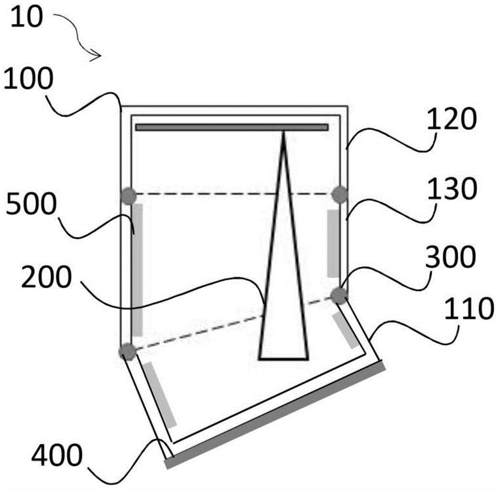
图2示出了具有对准设备101的传感器壳体100,传感器壳体100包含传感器装置10。传感器壳体100的对准设备101包括第一部分110、第二部分120和第三部分130。FIG. 2 shows a
第一部分110具有第一腔室115,并作为传感器壳体的下部布置。第二部分120具有第二部分125,并作为传感器壳体的上部布置。第三部分130具有第三腔室135,并布置在第一部分110和第二部分120之间。The
第一部分110、第二部分120和第三部分130连接在一起,并被构造为一体地、圆柱形地形成传感器壳体100。在此,第二部分120被设计为中空圆柱体,并且第一部分110和第三部分130分别被设计为斜切的中空圆柱体。传感器壳体100可以是完全封闭的且/或不能以非破坏性的方式打开。The
第三部分130被设计为能够分别相对于第一部分110和/或第二部分120旋转。换句话说,各个壳体部件(即,第一部分110、第二部分120和第三部分130)能够相对彼此旋转。因此,传感器壳体100具有两个旋转轴线或两个旋转面,这些旋转面是布置在第一部分110和第三部分130之间的斜面和布置在第二部分120和第三部分130之间的直面。The
传感器壳体的腔室115、125、135可以形成公共腔室,或者每者被设计为单独的封闭腔室。传感器壳体110的旋转面可以分别由第一部分110和第三部分130之间以及第二部分120和第三部分130之间的连接处的切割面或切割边缘形成。在形成公共腔室的情况下,旋转面可以是虚拟的旋转面。The
密封元件300可以设置在第一、第二和第三部分110、120、130之间的连接处,以密封传感器壳体100。A sealing
腔室中可能存在空气或是真空的。此外,由吸收材料制成的吸收设备500例如可以设置在第一腔室115和/或第三腔室135中,或者设置在第一部分110和第三部分130的内壁上。吸收设备500可被构造为保护测量信号在穿过对准设备时不被偏转或衰减,从而可以消除或至少最小化对测量结果的干扰影响。There may be air or a vacuum in the chamber. Furthermore, an
传感器装置10的传感器可以具有天线200,该天线可以例如是喇叭天线、阵列天线、透镜天线或抛物面天线。The sensor of the
如图4a至4c所示,天线200通过第二部分120被容纳在传感器壳体100中,或者固定或布置在第二腔室125的上部中。As shown in FIGS. 4 a to 4 c , the
此外,图3作为传感器装置10的俯视图示出了天线200可以偏心地布置在传感器壳体100中。Furthermore, FIG. 3 shows as a top view of the
图4a至4c中的传感器装置10还包括具有电路板的电子设备220,该电子设备连接到天线200,并安装和固定在传感器壳体的上部中或第二部分120中。The
替代地,如图6a至6b所示,天线200可以居中地固定在传感器壳体100中或第二部分120的腔室125中。天线200被设计为突出到第一腔室115和/或第三腔室135中。Alternatively, the
传感器装置10还包括安装设备400,该安装设备设置在传感器壳体100的下侧处。在将传感器装置安装在容器20的倾斜顶部上的情况下,安装设备400布置在第一部分110和容器20之间,并被构造为通过第一部分100安装传感器装置10。安装可以通过粘合装配经由粘合面进行,即,安装设备400可以是诸如胶带之类的粘合物。因此,粘合面可以设置在传感器壳体100或第一部分110的下侧与容器顶部之间。替代地或补充地,安装设备400可以是安装板。The
在将具有偏心布置的天线200的传感器装置10安装在容器顶部上时,对准设备101可被构造为通过旋转第一部分110和/或第二部分120和/或第三部分130来改变传感器的测量信号30的辐射方向。When installing the
图4a示出了例如在不旋转各个部分110、120、130的情况下传感器壳体100仍为圆柱形并且天线位于传感器壳体100的左侧且在垂直方向上对准。在图4b中,在安装到倾斜的容器顶部之后,可以旋转第三部分120(例如,旋转90度),使得圆柱形的第二部分120能够水平布置或者天线200的垂直朝向和容器顶部之间能够形成锐角。此外,可以旋转第二部分(例如,旋转90度),使得如图4b所示,天线200可以居中地定位在第二部分中。因此,可以通过旋转第三部分130和/或第二部分120来改变天线200在传感器壳体100中的位置。与图4b相比,图4c中的容器20具有更倾斜的容器顶部,传感器装置10通过安装设备400安装在该容器顶部上。可以进一步旋转第三部分130(例如,旋转180度),使得第二部分120能够水平布置或者天线200的垂直对准方向和容器顶部之间能够形成更小的锐角。也可以旋转第二部分120(例如,旋转180度),使得如图4c的侧视图所示,天线200可以定位在右侧,或者相对于旋转之前天线所处的左侧位置对称地定位。Fig. 4a shows that the
通过在借助于第一部分110进行安装时旋转第二部分120和/或旋转第三部分130,天线200可被形成为使得天线200能够定位在容器顶部的最高位置处。测量传感器或天线可以在最高位置处穿过容器顶部辐射测量信号,并且可以以垂直于填充材料的表面的方式或朝向松散材料辐射测量信号。By rotating the
利用传感器装置10,传感器可以有利地实现在具有倾斜(例如,圆锥形或圆形或碟形)容器盖的过程容器上的方便安装并同时可靠地测量。With the
如图6a至6b所示,可以在传感器装置10或传感器壳体30(例如,第一部分110)中额外设置偏振设备,该偏振设备被构造为通过旋转第一部分110、第二部分120或第三部分130来改变测量信号30的偏振。替代地或补充地,也可以将偏振设备设置在第一部分和第二部分之间或第一部分和容器顶部之间。尤其当天线200居中地布置在第二部分200中并因此不能通过旋转第二部分来改变天线的位置或高度时,且/或当容器顶部尤其倾斜地设计并且有必要对测量信号的辐射方向进行额外的调节(例如微调)时,通过设置偏振设备,可以促进和显著优化天线200或测量信号30朝向填充材料或松散材料的对准的改变。As shown in FIGS. 6a to 6b, a polarization device may additionally be provided in the
作为图4a至4c和图6a至6b中的传感器装置10的由三部分形成的传感器壳体的替代方案,图5a至5c示出了包括具有对准设备的两部分式传感器壳体100的传感器装置10,该传感器壳体100包括两个直接相互连接的部分,即,作为下部的第一部分110和作为上部的第二部分120。因此,传感器装置10的传感器壳体100可以省去作为中间部件的第三部分。因此,具有两个部分110、120的传感器装置可以具有紧凑的结构。As an alternative to the three-part sensor housing of the
图5a至5c中的传感器装置10在第一部分110和第二部分120的连接处具有单个旋转轴线或旋转面。第一部分110和第二部分120分别具有斜切的中空圆柱体的形状并且被构造为一体地、圆柱形地形成传感器壳体100。旋转面是布置在第一部分和第二部分之间的斜面。第一部分和第二部分可以经由该斜面相对彼此旋转,使得传感器壳体100可以不再形成为圆柱形。The
因此,传感器装置的对准设备被构造为通过能够相对彼此旋转的第一部分和第二部分来改变传感器的测量信号30的辐射方向。天线200也可以偏心地容纳或布置在第二部分中。此外,天线200被设计为突出到第一腔室中。在图5a中,传感器壳体100形成为圆柱形,并且天线200布置在传感器壳体中,例如布置在中心的左侧。在传感器装置安装在倾斜的容器顶部上时,第二部分120可以通过对准设备相对于第一部分110旋转一定程度,以至于天线可以在如图5b所示的侧视图中居中地布置,或者可以在如图5c所示的另一侧视图中布置在中心的右侧。有利的是,通过偏心布置并旋转第二部分,天线200可以安装到传感器壳体的壳体部分的较短部分上。Accordingly, the alignment device of the sensor arrangement is configured to change the radiation direction of the
图7a至7b示出了根据作为图4a至4c中的传感器装置的替代实施例的传感器装置。该传感器装置包括传感器壳体100a,传感器壳体100不是一体形成的,而是具有两个可分离的壳体单元,即,第一壳体单元和第二壳体单元。第一壳体单元由具有第一腔室115a的第一部分110a和具有第三腔室135a的第三部分130a形成,并且可以是中空圆柱体的形式,而第二壳体单元作为单独的壳体单元由第二部分120a以中空圆柱体的形式形成。Figures 7a to 7b show a sensor arrangement according to an alternative embodiment to that of figures 4a to 4c. The sensor device includes a
第二安装设备400a设置在第一壳体单元和第二壳体单元之间并且被构造为连接第一壳体单元和第二壳体单元。例如,第二壳体单元可以粘合到第一壳体单元上。The
包括天线200和电路板220的传感器或雷达传感器容纳或布置在第二壳体单元或第二部分120a中。因此,内部布置有传感器的封闭壳体单元可以形成自给式测量传感器。A sensor or a radar sensor including the
此外,第一壳体单元可被设计为单独的对准设备,或被设计成用于安装和对准测量传感器的适配器。通过单独形成的第二壳体单元,可以容易更换传感器,并且第二壳体单元可以作为适配器通用于不同类型的传感器。Furthermore, the first housing unit can be designed as a separate alignment device or as an adapter for mounting and aligning the measuring sensor. By the second housing unit formed separately, the sensor can be easily replaced, and the second housing unit can be commonly used as an adapter for different types of sensors.
此外,如图7a所示,第一腔室115a和第三腔室135a可以形成公共腔室,并且对准设备因此可以具有虚拟的旋转面。替代地,如图7b所示,第一腔室115a和第三腔室135a可以分别具有自身的封闭腔室。Furthermore, as shown in Fig. 7a, the
作为吸收设备的替代和补充,可以将过滤器600或压力补偿过滤器设置在第一壳体单元的第一腔室115a和/或第三腔室135a中,以平衡壳体单元内部和外部的空气压力。如果第一腔室115a和第三腔室135a如图7a所示地形成公共腔室,则可以设置过滤器。如果第一腔室115a和第三腔室135a如图7b所示地分别具有自身的封闭腔室,则可以将过滤器设置在各自的封闭腔室中。As an alternative and in addition to the absorption device, a
图8a至8b示出了根据另一实施例的传感器装置。传感器装置包括传感器100和传感器壳体100b,传感器包括天线200和电子设备或电路板220,传感器壳体100b包括对准设备,该对准设备包括支架形式的第一部分110b和中空球体或球体分段形式的第二部分120b。第二部分120b的中空球体分段可以是关节套。Figures 8a to 8b show a sensor arrangement according to another embodiment. The sensor arrangement comprises a
作为图8a至8b中的传感器装置的另一实施例,图9a至9b和10a至10b中的传感器装置包括具有扁平球体分段形式的第二部分120b的传感器壳体100b。As a further embodiment of the sensor device in Figures 8a to 8b, the sensor device in Figures 9a to 9b and 10a to 10b comprises a
替代地,第一部分110b可以为中空圆柱体的形式,并具有第一腔室115b。对准设备或传感器壳体100b的第二部分120b具有第一腔室100b,在该腔室中容纳或布置有传感器或天线200和电路板220。第一部分110b和第二部分110b可以例如通过螺纹连接或卡扣连接相互连接并能够相对彼此旋转。换句话说,球形的第二部分120b中的传感器可以像球一样被夹紧或布置在作为保持件的第一部分110b上。Alternatively, the
密封元件300b可以设置在连接处,并且被构造为密封传感器壳体100b。A sealing
安装设备400(例如,胶带)可以在安装传感器装置10时设置在第一部分100b和容器20之间,并且被构造为通过第一部分110b将传感器装置10安装到容器20上。通过粘合安装,传感器装置10可以容易安装到容器顶盖(特别是如图8a、图9a至9b或图10a至10b所示的倾斜的容器顶盖)上,使得第一部分110b定位在第二部分120b的下方,并且能够穿过传感器壳体100b、第一部分110b的下侧和容器壁辐射测量信号。通过旋转第一部分110b和/或第二部分120b,传感器装置10可以借助于安装设备400如图8b所示地设置在容器的外侧或紧邻容器设置,使得第一部分110b可以布置在第二部分120b的上方,并且能够穿过传感器壳体100b和容器壁但不穿过第一部分110b辐射测量信号。因此,传感器装置的安装可以自由地进行。例如,传感器可以旋转360度并自由地对准。A mounting device 400 (eg, adhesive tape) may be provided between the
图9a和9b示出了传感器装置10还可以包括波束偏转设备700,该波束偏转设备可以例如是透镜并设置在第二部分120b的下部中,并且被构造为使测量信号朝向容器中的填充材料偏转。因此,除了通过对准设备旋转第一部分和/或第二部分之外,设置的波束偏转设备700可用于改变传感器的测量信号的辐射方向。Figures 9a and 9b show that the
此外,可以将过滤器600或压力补偿过滤器和/或吸收设备500设置在第一部分110b的第一腔室115b中。Furthermore, a
例如,天线200可以居中(如图9a至9b所示)地或偏心(如图10a至10b所示)地布置在第三部分120b中。通过将天线200偏心地布置,可以通过相对于第一部分110b旋转第二部分120b而改变天线200的位置,例如从图10a的左侧到图10b的右侧,并且仍可以改变测量信号的辐射方向。For example, the
图11a至11b示出了根据替代实施例的传感器装置10。传感器装置10包括具有对准设备的传感器壳体100c,该对准设备具有支撑设备形式的第一部分110c、中空圆柱体形式的第二部分120c和橡胶套筒形式的第三部分130c。第二部分120c通过连接设备118(例如,螺栓连接件)连接到第一部分110c。因此,第一部分110c可被设计为底座或安装支架。Figures 11a to 11b show a
橡胶套筒130c设置在第一部分与部分之间,并被构造为封闭第二部分120c中的传感器与第一部分110c的支撑设备之间的空间,或形成封闭的腔室以保护腔室不被环境中的异物进入。因此,传感器装置10可以长期可靠地用于室外的过程容器。The
还应注意,“包括”或“具有”不排除其它元件,不定冠词“一”或“一个”不排除多个。此外,应注意,已经参考其中一个上述实施例说明的特征也可以与上述其它实施例的其它特征组合使用。权利要求中的附图标记不应被解释为限制性的。It should also be noted that "comprising" or "having" does not exclude other elements, and the indefinite article "a" or "an" does not exclude a plurality. Furthermore, it should be noted that features which have been described with reference to one of the above-described embodiments may also be used in combination with other features of other above-described embodiments. Reference signs in the claims should not be construed as limiting.
Claims (25)
Applications Claiming Priority (5)
| Application Number | Priority Date | Filing Date | Title |
|---|---|---|---|
| EPPCT/EP2020/060615 | 2020-04-15 | ||
| PCT/EP2020/060615 WO2021209129A1 (en) | 2020-04-15 | 2020-04-15 | Radar sensor having a spherical sensor housing |
| PCT/EP2020/060614 WO2021209128A1 (en) | 2020-04-15 | 2020-04-15 | Fastening device for a sensor |
| EPPCT/EP2020/060614 | 2020-04-15 | ||
| PCT/EP2020/076787 WO2021209162A1 (en) | 2020-04-15 | 2020-09-24 | Sensor assembly with alignment device |
Publications (1)
| Publication Number | Publication Date |
|---|---|
| CN115427770A true CN115427770A (en) | 2022-12-02 |
Family
ID=72560618
Family Applications (1)
| Application Number | Title | Priority Date | Filing Date |
|---|---|---|---|
| CN202080099837.XA Pending CN115427770A (en) | 2020-04-15 | 2020-09-24 | Sensor device with alignment device |
Country Status (4)
| Country | Link |
|---|---|
| US (1) | US20230130890A1 (en) |
| EP (1) | EP4136416B1 (en) |
| CN (1) | CN115427770A (en) |
| WO (1) | WO2021209162A1 (en) |
Families Citing this family (4)
| Publication number | Priority date | Publication date | Assignee | Title |
|---|---|---|---|---|
| JP2025516072A (en) * | 2022-05-09 | 2025-05-26 | エル.ジェイ.スター,インコーポレイテッド | Method for measuring the level at a container outlet and a rotatable sensor for carrying out said method - Patents.com |
| JP2024000252A (en) * | 2022-06-20 | 2024-01-05 | 株式会社ノーケン | sensor device |
| JP2024011856A (en) * | 2022-07-15 | 2024-01-25 | ホシデン株式会社 | distance sensor module |
| DE102022126507A1 (en) * | 2022-10-12 | 2024-04-18 | Vega Grieshaber Kg | Measuring device, fastening system, measuring arrangement and method |
Citations (6)
| Publication number | Priority date | Publication date | Assignee | Title |
|---|---|---|---|---|
| CN102042859A (en) * | 2009-10-14 | 2011-05-04 | 罗伯特·博世有限公司 | Device for measuring the fill level in a liquid container |
| US20150048963A1 (en) * | 2013-08-14 | 2015-02-19 | Vega Grieshaber Kg | Radar beam deflection unit for a radar level indicator |
| CN105874307A (en) * | 2014-02-11 | 2016-08-17 | Vega格里沙贝两合公司 | Filling level measuring device with foldable antenna device |
| CN105981220A (en) * | 2014-02-21 | 2016-09-28 | Vega格里沙贝两合公司 | Level measuring device including energy transmission device |
| CN106030901A (en) * | 2014-02-21 | 2016-10-12 | Vega格里沙贝两合公司 | Level indicator featuring optimized energy supply |
| CN109564127A (en) * | 2016-07-18 | 2019-04-02 | 通快机床两合公司 | Method and apparatus for determining the controlling level of the spatial discrimination in bulk material container |
Family Cites Families (6)
| Publication number | Priority date | Publication date | Assignee | Title |
|---|---|---|---|---|
| JPS63210733A (en) * | 1987-02-27 | 1988-09-01 | Takuwa:Kk | Method and device for measuring depth of snow coverage |
| US9404787B2 (en) * | 2014-02-26 | 2016-08-02 | Finetek Co., Ltd. | Level measuring device with an integratable lens antenna |
| CN106415923A (en) * | 2014-05-30 | 2017-02-15 | Vega格里沙贝两合公司 | Antenna array |
| EP3073229B1 (en) * | 2015-03-27 | 2022-06-22 | VEGA Grieshaber KG | Radar fill level measuring device with integrated limit level sensor |
| WO2017084701A1 (en) * | 2015-11-17 | 2017-05-26 | Vega Grieshaber Kg | Antenna device and method for operating an antenna device |
| EP3569990B1 (en) * | 2018-05-17 | 2021-02-17 | VEGA Grieshaber KG | Attachment assembly for a radar fill level measuring device |
-
2020
- 2020-09-24 CN CN202080099837.XA patent/CN115427770A/en active Pending
- 2020-09-24 EP EP20775025.8A patent/EP4136416B1/en active Active
- 2020-09-24 WO PCT/EP2020/076787 patent/WO2021209162A1/en not_active Ceased
- 2020-09-24 US US17/996,140 patent/US20230130890A1/en active Pending
Patent Citations (6)
| Publication number | Priority date | Publication date | Assignee | Title |
|---|---|---|---|---|
| CN102042859A (en) * | 2009-10-14 | 2011-05-04 | 罗伯特·博世有限公司 | Device for measuring the fill level in a liquid container |
| US20150048963A1 (en) * | 2013-08-14 | 2015-02-19 | Vega Grieshaber Kg | Radar beam deflection unit for a radar level indicator |
| CN105874307A (en) * | 2014-02-11 | 2016-08-17 | Vega格里沙贝两合公司 | Filling level measuring device with foldable antenna device |
| CN105981220A (en) * | 2014-02-21 | 2016-09-28 | Vega格里沙贝两合公司 | Level measuring device including energy transmission device |
| CN106030901A (en) * | 2014-02-21 | 2016-10-12 | Vega格里沙贝两合公司 | Level indicator featuring optimized energy supply |
| CN109564127A (en) * | 2016-07-18 | 2019-04-02 | 通快机床两合公司 | Method and apparatus for determining the controlling level of the spatial discrimination in bulk material container |
Also Published As
| Publication number | Publication date |
|---|---|
| US20230130890A1 (en) | 2023-04-27 |
| WO2021209162A1 (en) | 2021-10-21 |
| EP4136416A1 (en) | 2023-02-22 |
| EP4136416B1 (en) | 2025-10-29 |
Similar Documents
| Publication | Publication Date | Title |
|---|---|---|
| CN115427770A (en) | Sensor device with alignment device | |
| US11774277B2 (en) | Radar sensor for object detection | |
| CN110631659B (en) | Level and surface thermometer | |
| US9658096B2 (en) | Radar level gauge inclination system | |
| US20210026001A1 (en) | Radar sensor, interchangeable radar sensor arrangement, field device and container | |
| JP2008544215A (en) | Geodetic target and survey system | |
| US20210080310A1 (en) | Floating roof monitoring | |
| US20230296422A1 (en) | Radar sensor with spherical sensor housing | |
| US12099137B2 (en) | Radar module comprising a microwave chip | |
| TW202104924A (en) | Multi dimensional reflection microwave barrier | |
| US9869576B2 (en) | Optical liquid level detection sensor and liquid overfill prevention system comprising such sensor | |
| US20080011970A1 (en) | Non-contact sensor for detecting material level in a container | |
| US20080309948A1 (en) | Process and device for controlling a filling level of silos containing loose materials | |
| US20190339100A1 (en) | Sensor case | |
| US20230160738A1 (en) | Self-sufficient display for fill level and limit level measuring devices | |
| WO2019157024A2 (en) | Sensor device for distance offset measurements | |
| KR20230002566A (en) | Mounting device for sensor | |
| CN118011375B (en) | A three-dimensional material measurement system with interference shielding function | |
| KR102894488B1 (en) | Solid State 3D Lidar Scanners And Their Application System | |
| US20240019536A1 (en) | Distance sensor module | |
| RU2777143C1 (en) | Radar sensor for object detection | |
| CA3231336A1 (en) | Sensor device, sensor arrangement and method for measuring radiation | |
| EP1804039A1 (en) | Process and device for controlling a filling level |
Legal Events
| Date | Code | Title | Description |
|---|---|---|---|
| PB01 | Publication | ||
| PB01 | Publication | ||
| SE01 | Entry into force of request for substantive examination | ||
| SE01 | Entry into force of request for substantive examination |