CN115476830A - electromechanical brake - Google Patents
electromechanical brake Download PDFInfo
- Publication number
- CN115476830A CN115476830A CN202210671575.0A CN202210671575A CN115476830A CN 115476830 A CN115476830 A CN 115476830A CN 202210671575 A CN202210671575 A CN 202210671575A CN 115476830 A CN115476830 A CN 115476830A
- Authority
- CN
- China
- Prior art keywords
- current
- pressing unit
- point
- initial position
- brake disc
- Prior art date
- Legal status (The legal status is an assumption and is not a legal conclusion. Google has not performed a legal analysis and makes no representation as to the accuracy of the status listed.)
- Granted
Links
Images


Classifications
-
- B—PERFORMING OPERATIONS; TRANSPORTING
- B60—VEHICLES IN GENERAL
- B60T—VEHICLE BRAKE CONTROL SYSTEMS OR PARTS THEREOF; BRAKE CONTROL SYSTEMS OR PARTS THEREOF, IN GENERAL; ARRANGEMENT OF BRAKING ELEMENTS ON VEHICLES IN GENERAL; PORTABLE DEVICES FOR PREVENTING UNWANTED MOVEMENT OF VEHICLES; VEHICLE MODIFICATIONS TO FACILITATE COOLING OF BRAKES
- B60T13/00—Transmitting braking action from initiating means to ultimate brake actuator with power assistance or drive; Brake systems incorporating such transmitting means, e.g. air-pressure brake systems
- B60T13/74—Transmitting braking action from initiating means to ultimate brake actuator with power assistance or drive; Brake systems incorporating such transmitting means, e.g. air-pressure brake systems with electrical assistance or drive
- B60T13/741—Transmitting braking action from initiating means to ultimate brake actuator with power assistance or drive; Brake systems incorporating such transmitting means, e.g. air-pressure brake systems with electrical assistance or drive acting on an ultimate actuator
-
- B—PERFORMING OPERATIONS; TRANSPORTING
- B60—VEHICLES IN GENERAL
- B60T—VEHICLE BRAKE CONTROL SYSTEMS OR PARTS THEREOF; BRAKE CONTROL SYSTEMS OR PARTS THEREOF, IN GENERAL; ARRANGEMENT OF BRAKING ELEMENTS ON VEHICLES IN GENERAL; PORTABLE DEVICES FOR PREVENTING UNWANTED MOVEMENT OF VEHICLES; VEHICLE MODIFICATIONS TO FACILITATE COOLING OF BRAKES
- B60T13/00—Transmitting braking action from initiating means to ultimate brake actuator with power assistance or drive; Brake systems incorporating such transmitting means, e.g. air-pressure brake systems
- B60T13/74—Transmitting braking action from initiating means to ultimate brake actuator with power assistance or drive; Brake systems incorporating such transmitting means, e.g. air-pressure brake systems with electrical assistance or drive
-
- B—PERFORMING OPERATIONS; TRANSPORTING
- B60—VEHICLES IN GENERAL
- B60T—VEHICLE BRAKE CONTROL SYSTEMS OR PARTS THEREOF; BRAKE CONTROL SYSTEMS OR PARTS THEREOF, IN GENERAL; ARRANGEMENT OF BRAKING ELEMENTS ON VEHICLES IN GENERAL; PORTABLE DEVICES FOR PREVENTING UNWANTED MOVEMENT OF VEHICLES; VEHICLE MODIFICATIONS TO FACILITATE COOLING OF BRAKES
- B60T7/00—Brake-action initiating means
- B60T7/02—Brake-action initiating means for personal initiation
- B60T7/04—Brake-action initiating means for personal initiation foot actuated
- B60T7/042—Brake-action initiating means for personal initiation foot actuated by electrical means, e.g. using travel or force sensors
-
- F—MECHANICAL ENGINEERING; LIGHTING; HEATING; WEAPONS; BLASTING
- F16—ENGINEERING ELEMENTS AND UNITS; GENERAL MEASURES FOR PRODUCING AND MAINTAINING EFFECTIVE FUNCTIONING OF MACHINES OR INSTALLATIONS; THERMAL INSULATION IN GENERAL
- F16D—COUPLINGS FOR TRANSMITTING ROTATION; CLUTCHES; BRAKES
- F16D55/00—Brakes with substantially-radial braking surfaces pressed together in axial direction, e.g. disc brakes
- F16D55/02—Brakes with substantially-radial braking surfaces pressed together in axial direction, e.g. disc brakes with axially-movable discs or pads pressed against axially-located rotating members
- F16D55/22—Brakes with substantially-radial braking surfaces pressed together in axial direction, e.g. disc brakes with axially-movable discs or pads pressed against axially-located rotating members by clamping an axially-located rotating disc between movable braking members, e.g. movable brake discs or brake pads
- F16D55/224—Brakes with substantially-radial braking surfaces pressed together in axial direction, e.g. disc brakes with axially-movable discs or pads pressed against axially-located rotating members by clamping an axially-located rotating disc between movable braking members, e.g. movable brake discs or brake pads with a common actuating member for the braking members
- F16D55/225—Brakes with substantially-radial braking surfaces pressed together in axial direction, e.g. disc brakes with axially-movable discs or pads pressed against axially-located rotating members by clamping an axially-located rotating disc between movable braking members, e.g. movable brake discs or brake pads with a common actuating member for the braking members the braking members being brake pads
- F16D55/226—Brakes with substantially-radial braking surfaces pressed together in axial direction, e.g. disc brakes with axially-movable discs or pads pressed against axially-located rotating members by clamping an axially-located rotating disc between movable braking members, e.g. movable brake discs or brake pads with a common actuating member for the braking members the braking members being brake pads in which the common actuating member is moved axially, e.g. floating caliper disc brakes
-
- F—MECHANICAL ENGINEERING; LIGHTING; HEATING; WEAPONS; BLASTING
- F16—ENGINEERING ELEMENTS AND UNITS; GENERAL MEASURES FOR PRODUCING AND MAINTAINING EFFECTIVE FUNCTIONING OF MACHINES OR INSTALLATIONS; THERMAL INSULATION IN GENERAL
- F16D—COUPLINGS FOR TRANSMITTING ROTATION; CLUTCHES; BRAKES
- F16D65/00—Parts or details
- F16D65/14—Actuating mechanisms for brakes; Means for initiating operation at a predetermined position
- F16D65/16—Actuating mechanisms for brakes; Means for initiating operation at a predetermined position arranged in or on the brake
- F16D65/18—Actuating mechanisms for brakes; Means for initiating operation at a predetermined position arranged in or on the brake adapted for drawing members together, e.g. for disc brakes
-
- F—MECHANICAL ENGINEERING; LIGHTING; HEATING; WEAPONS; BLASTING
- F16—ENGINEERING ELEMENTS AND UNITS; GENERAL MEASURES FOR PRODUCING AND MAINTAINING EFFECTIVE FUNCTIONING OF MACHINES OR INSTALLATIONS; THERMAL INSULATION IN GENERAL
- F16D—COUPLINGS FOR TRANSMITTING ROTATION; CLUTCHES; BRAKES
- F16D65/00—Parts or details
- F16D65/14—Actuating mechanisms for brakes; Means for initiating operation at a predetermined position
- F16D65/16—Actuating mechanisms for brakes; Means for initiating operation at a predetermined position arranged in or on the brake
- F16D65/18—Actuating mechanisms for brakes; Means for initiating operation at a predetermined position arranged in or on the brake adapted for drawing members together, e.g. for disc brakes
- F16D65/183—Actuating mechanisms for brakes; Means for initiating operation at a predetermined position arranged in or on the brake adapted for drawing members together, e.g. for disc brakes with force-transmitting members arranged side by side acting on a spot type force-applying member
-
- F—MECHANICAL ENGINEERING; LIGHTING; HEATING; WEAPONS; BLASTING
- F16—ENGINEERING ELEMENTS AND UNITS; GENERAL MEASURES FOR PRODUCING AND MAINTAINING EFFECTIVE FUNCTIONING OF MACHINES OR INSTALLATIONS; THERMAL INSULATION IN GENERAL
- F16D—COUPLINGS FOR TRANSMITTING ROTATION; CLUTCHES; BRAKES
- F16D66/00—Arrangements for monitoring working conditions, e.g. wear, temperature
- F16D66/02—Apparatus for indicating wear
- F16D66/021—Apparatus for indicating wear using electrical detection or indication means
-
- B—PERFORMING OPERATIONS; TRANSPORTING
- B60—VEHICLES IN GENERAL
- B60Y—INDEXING SCHEME RELATING TO ASPECTS CROSS-CUTTING VEHICLE TECHNOLOGY
- B60Y2400/00—Special features of vehicle units
- B60Y2400/30—Sensors
- B60Y2400/301—Sensors for position or displacement
-
- B—PERFORMING OPERATIONS; TRANSPORTING
- B60—VEHICLES IN GENERAL
- B60Y—INDEXING SCHEME RELATING TO ASPECTS CROSS-CUTTING VEHICLE TECHNOLOGY
- B60Y2400/00—Special features of vehicle units
- B60Y2400/30—Sensors
- B60Y2400/308—Electric sensors
- B60Y2400/3084—Electric currents sensors
-
- F—MECHANICAL ENGINEERING; LIGHTING; HEATING; WEAPONS; BLASTING
- F16—ENGINEERING ELEMENTS AND UNITS; GENERAL MEASURES FOR PRODUCING AND MAINTAINING EFFECTIVE FUNCTIONING OF MACHINES OR INSTALLATIONS; THERMAL INSULATION IN GENERAL
- F16D—COUPLINGS FOR TRANSMITTING ROTATION; CLUTCHES; BRAKES
- F16D66/00—Arrangements for monitoring working conditions, e.g. wear, temperature
- F16D2066/003—Position, angle or speed
-
- F—MECHANICAL ENGINEERING; LIGHTING; HEATING; WEAPONS; BLASTING
- F16—ENGINEERING ELEMENTS AND UNITS; GENERAL MEASURES FOR PRODUCING AND MAINTAINING EFFECTIVE FUNCTIONING OF MACHINES OR INSTALLATIONS; THERMAL INSULATION IN GENERAL
- F16D—COUPLINGS FOR TRANSMITTING ROTATION; CLUTCHES; BRAKES
- F16D66/00—Arrangements for monitoring working conditions, e.g. wear, temperature
- F16D2066/006—Arrangements for monitoring working conditions, e.g. wear, temperature without direct measurement of the quantity monitored, e.g. wear or temperature calculated form force and duration of braking
-
- F—MECHANICAL ENGINEERING; LIGHTING; HEATING; WEAPONS; BLASTING
- F16—ENGINEERING ELEMENTS AND UNITS; GENERAL MEASURES FOR PRODUCING AND MAINTAINING EFFECTIVE FUNCTIONING OF MACHINES OR INSTALLATIONS; THERMAL INSULATION IN GENERAL
- F16D—COUPLINGS FOR TRANSMITTING ROTATION; CLUTCHES; BRAKES
- F16D2121/00—Type of actuator operation force
- F16D2121/18—Electric or magnetic
- F16D2121/24—Electric or magnetic using motors
-
- F—MECHANICAL ENGINEERING; LIGHTING; HEATING; WEAPONS; BLASTING
- F16—ENGINEERING ELEMENTS AND UNITS; GENERAL MEASURES FOR PRODUCING AND MAINTAINING EFFECTIVE FUNCTIONING OF MACHINES OR INSTALLATIONS; THERMAL INSULATION IN GENERAL
- F16D—COUPLINGS FOR TRANSMITTING ROTATION; CLUTCHES; BRAKES
- F16D2125/00—Components of actuators
- F16D2125/18—Mechanical mechanisms
- F16D2125/20—Mechanical mechanisms converting rotation to linear movement or vice versa
- F16D2125/34—Mechanical mechanisms converting rotation to linear movement or vice versa acting in the direction of the axis of rotation
- F16D2125/40—Screw-and-nut
Landscapes
- Engineering & Computer Science (AREA)
- General Engineering & Computer Science (AREA)
- Mechanical Engineering (AREA)
- Transportation (AREA)
- Braking Arrangements (AREA)
- Braking Systems And Boosters (AREA)
Abstract
一种机电制动器,包括:制动盘;摩擦块;按压单元,其被配置为朝向所述制动盘按压所述摩擦块;电机,向所述按压单元提供功率;电流传感器;位置传感器,其被配置为测量所述按压单元的位置;以及初始位置计算单元,其计算所述按压单元的初始位置或接触点中的至少一个,其中所述按压单元被配置为通过第一检查点和第二检查点,在第一检查点处第一电流被测量,在第二检查点处大于所述第一电流的第二电流被测量,其中,所述初始位置计算单元基于所述第一电流、所述第一检查点、所述第二电流和所述第二检查点计算所述初始位置或所述接触点中的至少一个。
An electromechanical brake comprising: a brake disc; a friction block; a pressing unit configured to press the friction block toward the brake disc; a motor that supplies power to the pressing unit; a current sensor; a position sensor that configured to measure the position of the pressing unit; and an initial position calculation unit that calculates at least one of an initial position or a contact point of the pressing unit, wherein the pressing unit is configured to pass through a first checkpoint and a second checkpoint A check point at which a first current is measured and at a second check point a second current greater than the first current is measured, wherein the initial position calculation unit is based on the first current, the At least one of the initial position or the contact point is calculated based on the first checkpoint, the second current and the second checkpoint.
Description
技术领域technical field
本公开涉及一种机电制动器。更具体地说,本公开涉及一种具有位置传感器和电流传感器的机电制动器。The present disclosure relates to an electromechanical brake. More specifically, the present disclosure relates to an electromechanical brake having a position sensor and a current sensor.
背景技术Background technique
本节描述的内容仅提供本公开的背景信息,并不构成现有技术。What is described in this section merely provides background information for the present disclosure and may not constitute prior art.
机电制动器(Electro-Mechanical Brake,EMB)正在被开发和被广泛的使用。机电制动器是作为电子驻车制动器(Electronic Parking Brake,EPB)发展起来的,但其使用范围最近正在扩大到替代传统的液压制动器的主制动器。EMB是这样的装置:其中由电机驱动的致动器安装在制动卡钳上,因此车辆由电机驱动力直接制动,而无需制动液等介质。由于EMB的机制与电子驻车制动器(Electronic Parking Brake,EPB)相似,但主要用于主制动,不像EPB。与EPB相比,EMB需要更高的制动响应和操作耐久性。此外,与液压制动器相比,机电制动器的结构更简单,制动响应速度更高,控制更精确,从而提高制动稳定性。Electro-Mechanical Brake (EMB) is being developed and widely used. Electromechanical brakes were developed as Electronic Parking Brakes (EPB), but their use has recently been expanded to replace conventional hydraulic brakes as main brakes. EMB is a device in which an actuator driven by a motor is mounted on a brake caliper, so that the vehicle is directly braked by the driving force of the motor without the need for a medium such as brake fluid. Since the mechanism of EMB is similar to Electronic Parking Brake (EPB), but it is mainly used for main braking, unlike EPB. Compared with EPB, EMB requires higher braking response and operating durability. In addition, compared with hydraulic brakes, electromechanical brakes have a simpler structure, higher braking response speed, and more precise control, thereby improving braking stability.
EMB使用负载传感器产生驾驶员所需的目标制动力。配备负载传感器的EMB可以精确测量夹紧力。然而,如果EMB配备了负载传感器,则安装传感器的部件的设计变得复杂,其制造成本增加。此外,EMB的尺寸由于传感器安装而可能不可避免地增加。EMB uses a load sensor to generate the target braking force required by the driver. The EMB equipped with a load cell can precisely measure the clamping force. However, if the EMB is equipped with a load sensor, the design of the part where the sensor is mounted becomes complicated and its manufacturing cost increases. Furthermore, the size of the EMB may inevitably increase due to sensor installation.
为了防止EMB制造成本的增加和尺寸的增加,EMB可以被设计成使得用电流传感器而不是负载传感器来测量流过产生制动力的电机的电流,然后基于测量的电流来测量或估计夹紧力。然而,通过测量流经电机的电流来估计夹紧力的方法存在问题,因为与使用负载传感器的情况相比会出现更大的误差,因此难以准确计算初始位置,即,按压单元接触摩擦块的位置。因此,很难保证车辆的稳定制动性能。In order to prevent an increase in manufacturing cost and an increase in size of the EMB, the EMB may be designed such that the current flowing through the motor generating the braking force is measured with a current sensor instead of a load sensor, and then the clamping force is measured or estimated based on the measured current. However, the method of estimating the clamping force by measuring the current flowing through the motor has a problem because a larger error occurs compared with the case of using a load sensor, so it is difficult to accurately calculate the initial position, that is, where the pressing unit contacts the friction block Location. Therefore, it is difficult to ensure stable braking performance of the vehicle.
发明内容Contents of the invention
鉴于以上所述,本公开提供了一种机电制动器,其能够基于两点更准确地计算初始位置,从而实现车辆的稳定制动性能。In view of the above, the present disclosure provides an electromechanical brake capable of more accurately calculating an initial position based on two points, thereby realizing stable braking performance of a vehicle.
本公开要解决的问题不限于上述问题,本领域技术人员从以下描述中将清楚地理解未提及的其他问题。Problems to be solved by the present disclosure are not limited to the above-mentioned problems, and other problems not mentioned will be clearly understood from the following description by those skilled in the art.
根据至少一个实施例,本公开提供了一种机电制动器,包括:制动盘;摩擦块,其被配置为面对制动盘并按压制动盘;按压单元,其被配置为朝向制动盘按压摩擦块;电机,向所述按压单元提供功率,以使所述按压单元按压所述摩擦块;电流传感器,其被配置为用于测量流过电机的电流的强度(i);位置传感器,其被配置为用于测量所述按压单元的位置(d);以及初始位置计算单元,其计算所述按压单元的初始位置或接触点中的至少一个,其中所述按压单元被配置为通过第一检查点(C1)以及第二检查点(C2),在所述第一检查点(C1)处第一电流(i1)被测量,以及在所述第二检查点(C2)处大于所述第一电流的第二电流(i2)被测量,其中,所述初始位置计算单元基于所述第一电流、所述第一检查点、所述第二电流和所述第二检查点计算所述初始位置或所述接触点中的至少一个。According to at least one embodiment, the present disclosure provides an electromechanical brake, including: a brake disc; a friction block configured to face the brake disc and press the brake disc; a pressing unit configured to face the brake disc pressing the friction block; a motor supplying power to the pressing unit to cause the pressing unit to press the friction block; a current sensor configured to measure the intensity (i) of the current flowing through the motor; a position sensor, It is configured to measure the position (d) of the pressing unit; and an initial position calculating unit which calculates at least one of an initial position or a contact point of the pressing unit, wherein the pressing unit is configured to pass the first A check point (C 1 ) at which a first current (i 1 ) is measured and a second check point (C 2 ) at which a first current (i 1 ) is measured, and at which second check point (C 2 ) at a second current (i 2 ) greater than the first current is measured, wherein the initial position calculation unit is based on the first current, the first check point, the second current and the first A second checkpoint computes at least one of the initial position or the contact point.
根据另一个实施例,本公开提供了一种初始化机电制动器的控制的方法,所述机电制动器包括:制动盘;摩擦块,其被配置为面对制动盘并按压制动盘;按压单元,其被配置为朝向制动盘按压摩擦块;电机,向所述按压单元提供功率,以使所述按压单元按压所述摩擦块;电流传感器,其被配置为用于测量流过电机的电流的强度;位置传感器,其被配置为用于测量所述按压单元的位置;以及初始位置计算单元,其计算所述按压单元的初始位置或接触点中的至少一个,所述方法包括:步骤:所述按压单元沿用于将所述摩擦块按压到第一电流被测量处的第一检查点的方向移动;步骤:所述按压单元朝向制动盘移动至第二检查点,在第二检查点处,第二电流被测量,第二电流大于或等于大于参考电流,参考电流大于第一电流;以及步骤:基于所述第一电流、所述第一检查点、所述第二电流和所述第二检查点计算所述初始位置或所述接触点中的至少一个。According to another embodiment, the present disclosure provides a method of initializing control of an electromechanical brake including: a brake disc; a friction pad configured to face the brake disc and press the brake disc; a pressing unit , which is configured to press the friction block toward the brake disc; a motor, which supplies power to the pressing unit, so that the pressing unit presses the friction block; a current sensor, which is configured to measure the current flowing through the motor intensity; a position sensor, which is configured to measure the position of the pressing unit; and an initial position calculation unit, which calculates at least one of the initial position or the contact point of the pressing unit, the method comprising: the steps of: The pressing unit moves along the direction for pressing the friction block to the first check point where the first current is measured; step: the pressing unit moves toward the brake disc to the second check point, at the second check point where a second current is measured, the second current is greater than or equal to a reference current greater than the first current; and the step of: based on the first current, the first check point, the second current and the A second checkpoint calculates at least one of the initial position or the contact point.
如上所述,本公开的一个实施例提供了一种机电制动器,其可以基于两点更精确地计算初始位置,因此实现了车辆的稳定制动性能。As described above, one embodiment of the present disclosure provides an electromechanical brake that can more accurately calculate an initial position based on two points, thus realizing stable braking performance of a vehicle.
附图说明Description of drawings
图1是示出机电制动器的截面图。FIG. 1 is a cross-sectional view showing an electromechanical brake.
图2是示出按压单元的位置、电流和夹紧力根据时间的图。FIG. 2 is a graph showing the position, current, and clamping force of a pressing unit according to time.
图3是示出电流和夹紧力根据时间的图。Figure 3 is a graph showing current and clamping force as a function of time.
图4示出了机电制动器功率不同的每种情况下的距离-电流图。Figure 4 shows the distance-current diagram for each case with different electromechanical brake power.
图5是用于说明根据本公开实施例的初始位置计算方法的距离-电流图。FIG. 5 is a distance-current diagram for illustrating an initial position calculation method according to an embodiment of the present disclosure.
图6示出了根据本公开实施例的机电制动器的距离-电流图。FIG. 6 shows a distance-current diagram of an electromechanical brake according to an embodiment of the disclosure.
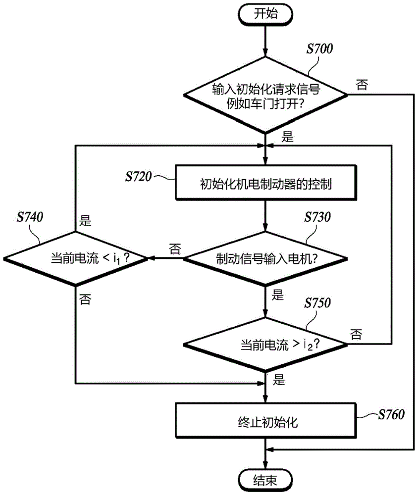
图7是示出根据本公开实施例的初始化机电制动器的控制的方法的流程图。FIG. 7 is a flowchart illustrating a method of initializing control of an electromechanical brake according to an embodiment of the present disclosure.
图8是示出根据本公开的初始化机电制动器的控制的过程的流程图。FIG. 8 is a flowchart illustrating a process of initializing control of an electromechanical brake according to the present disclosure.
附图标记:Reference signs:
100:制动盘 110:摩擦块100: brake disc 110: friction block
120:按压单元 130:电机120: Press unit 130: Motor
h.p:初始位置 c.p:接触点h.p: initial position c.p: contact point
C1:第一检查点 C2:第二检查点C 1 : first checkpoint C 2 : second checkpoint
C3:参考点 d1:第一距离C 3 : reference point d 1 : first distance
d2:第二距离 i1:第一电流d 2 : second distance i 1 : first current
i2:第二电流 P1:第一位置i 2 : second current P 1 : first position
P2:第二位置P 2 : second position
具体实施方式detailed description
下面参考附图描述本公开的一些示例性实施例。在下面的描述中,相似的附图标记优选地指定相似的元件,尽管这些元件在不同的附图中示出。此外,在以下对一些实施例的描述中,为了清楚和简洁,将省略对本文所结合的已知功能和配置的详细描述。Some exemplary embodiments of the present disclosure are described below with reference to the accompanying drawings. In the following description, like reference numerals preferably designate like elements, even though these elements are shown in different drawings. Also, in the following description of some embodiments, detailed descriptions of known functions and configurations incorporated herein will be omitted for clarity and conciseness.
此外,组件编号中的字母数字代码,如第一、第二、i)、ii)、a)、b)等,仅用于区分一个组件和另一个组件的目的,而不是暗示或建议组件的物质、指令或顺序。在本说明书中,当部件“包含”或“包括”组件时,它们意味着进一步包括其他组件,但不排除其他组件,除非有与之相反的特殊说明。In addition, alphanumeric codes in component numbers, such as first, second, i), ii), a), b), etc., are used only for the purpose of distinguishing one component from another and do not imply or suggest that the component Substance, instruction or sequence. In this specification, when components "comprise" or "include" a component, they mean that other components are further included, but not excluded, unless there is a special statement to the contrary.
图1是示出了机电制动器的截面图。FIG. 1 is a sectional view showing an electromechanical brake.
参考图1,根据本公开实施例的机电制动器包括制动盘100、摩擦块110、按压单元120、电机130、电流传感器(未显示)、位置传感器(未显示)、初始位置计算单元(未显示)。Referring to FIG. 1 , an electromechanical brake according to an embodiment of the present disclosure includes a
摩擦块110配置为面向制动盘100并按压制动盘100。一对摩擦块110可以安装在制动盘100的两侧,使其彼此相对。至少一部分摩擦块可容纳在卡钳壳180或载体190中,以引导摩擦块110,使得摩擦块110垂直于制动盘100的一侧移动。当活塞单元125按压摩擦块110时,摩擦块110可以朝向制动盘100滑动,其中摩擦块110被安装为使得至少一部分摩擦块容纳在载体190中。The
按压单元120被配置为朝着制动盘100按压摩擦块110。按压单元120施加到摩擦块110的夹紧力足够大,使得按压单元120的实际位移非常小,因此可能无法测量。在本公开中,由按压单元120朝向制动盘100的按压包括电机130沿增加施加到制动盘100的夹紧力的方向旋转的情况。The
按压单元120可以包括齿轮、按压单元120或活塞单元125中的至少一个。The
由电机130产生的旋转功率通过一个或多个齿轮传送到按压单元120。按压单元120朝向制动盘100平移摩擦块110。齿轮安装在靠近制动盘100的齿轮箱140中。更具体地说,按压单元120可以包括安装在卡钳壳180中的螺母单元123和螺栓单元121。当螺栓单元121通过齿轮旋转时,它与螺母单元123啮合以执行直线运动。安装在螺母单元123前部上的并由螺母单元123按压的活塞单元125与摩擦块110接触以按压摩擦块110。然而,本公开的机电制动器不限于此。本公开的机电制动器包括各种实施例,其中活塞单元125是螺母单元123本身,或者螺栓单元121执行平移运动,螺母单元123执行旋转运动。Rotational power generated by the
电机130向按压单元120提供功率,使得按压单元120按压摩擦块110。因为对车辆的踏板施加了行程,所以制动信号或制动释放信号被传送到电机130。响应于制动信号或制动释放信号而控制电机130的旋转力。制动信号或制动释放信号可由驾驶员的踏板行程产生。The
在本公开中,按压单元120的位置指按压单元120的摩擦块110的端面的位置。在本公开的一个实施例中,按压单元120的位置可以指活塞单元125的摩擦块110的端面的位置。在本公开中,距离是指从起始位置h.p(其将在下文中描述)到按压单元120的位置的距离。在本公开中,将按压单元120朝向制动盘100移动的方向定义为(+)方向。In the present disclosure, the position of the
位置传感器被配置为测量按压单元120的位置。如果在不考虑摩擦块110的磨损等因素的情况下确定按压单元120的位置,则可以粗略估计生产出来有一定的规格的摩擦块110的面向制动盘100的端面的位置。The position sensor is configured to measure the position of the
图2是示出按压单元120的位置、电流和夹紧力根据时间的图。FIG. 2 is a graph illustrating the position, current, and clamping force of the
图3是示出电流和夹紧力根据时间的图。Figure 3 is a graph showing current and clamping force as a function of time.
参考图1至3,机电制动器的按压单元120按压摩擦块110以产生制动力。这里,将按压单元120按压摩擦块110的力定义为夹紧力。夹紧力大致与电流传感器测量的电流的强度成正比,这将在后面描述。Referring to FIGS. 1 to 3 , the
由于按压单元120不接触并按压摩擦块110,因此摩擦块110可以与制动盘100间隔开。在这种情况下,无论按压单元120的移动如何,都不会产生夹紧力。Since the
按压单元120开始接触摩擦块110的距离称为接触点c.p。此外,按压单元120在按压释放方向上与接触点c.p间隔微小距离且不产生夹紧力的点被称为起始位置h.p。根据摩擦材料的材料规范,该微小距离的值可为约0.1mm至0.3mm。The distance at which the
当按压单元120从接触点c.p朝向制动盘100移动时,摩擦块110按压制动盘100的力增加。设置在制动盘100两侧的一对摩擦块110可以通过按压制动盘100的两侧来约束车轮的旋转。When the
当按压单元120的距离接近初始位置h.p时,距离-电流关系中摩擦块110的刚度在电流的强度(即夹紧力的大小)中不起主导作用。因此,当按压单元120的距离接近初始位置h.p时,距离-电流图被非线性地绘制。然而,随着按压单元120的距离增加,摩擦块110的刚度成为夹紧力大小中的主要变量,使得距离-电流接近线性关系。When the distance of the
图4示出了机电制动器功率不同的每种情况下的距离-电流图。Figure 4 shows the distance-current diagram for each case with different electromechanical brake power.
图5是用于说明根据本公开实施例的初始位置计算方法的距离-电流图。FIG. 5 is a distance-current diagram for illustrating an initial position calculation method according to an embodiment of the present disclosure.
参考图4和5,当距离接近零(zero,0)时,距离和电流具有非线性关系。随着距离增加,距离和电流变得更接近线性关系。在本公开中,距离小且距离和电流具有非线性关系的部分被称为非线性部分,而具有较大距离的部分被称为线性部分。由于距离和夹紧力在线性部分中大致具有线性关系,因此可以使用位置传感器相对准确地估计夹紧力。然而,仅使用位置传感器很难估计制动盘100和摩擦块110之间的接触点c.p或初始位置h.p。不应使用位置传感器而应使用电流传感器检测接触点c.p或初始位置h.p,这将在后面描述。Referring to Figures 4 and 5, when the distance is close to zero (zero, 0), the distance and current have a non-linear relationship. As distance increases, distance and current become more linear. In the present disclosure, a portion where the distance is small and the distance and current have a nonlinear relationship is referred to as a nonlinear portion, and a portion with a larger distance is referred to as a linear portion. Since distance and clamping force have approximately a linear relationship in the linear portion, the clamping force can be estimated relatively accurately using a position sensor. However, it is difficult to estimate the contact point c.p or the initial position h.p between the
电流传感器被配置为测量驱动电机130的电流的强度。电流传感器测量的电流强度大致与夹紧力成正比。因此,可以使用电流传感器测量的电流的强度来估计机电制动器的夹紧力。电流传感器可以不是新安装的以实现本公开的机电制动器,而可以使用安装在现有机电制动器的电机130中的电流传感器。The current sensor is configured to measure the strength of the current driving the
参考图3,由于电流传感器的分辨率低,且测量电流的噪声大,因此很难准确检测接触点c.p的位置。例如,如果确定检测到5A的电流强度的点是接触点c.p,当检测到如图3所示的电流强度时,很难准确确定哪一点是接触点c.p。Referring to Figure 3, due to the low resolution of the current sensor and the high noise of the measured current, it is difficult to accurately detect the position of the contact point c.p. For example, if it is determined that the point at which the current intensity of 5A is detected is the contact point c.p, when the current intensity as shown in FIG. 3 is detected, it is difficult to accurately determine which point is the contact point c.p.
通过从检测到预定电流强度的按压单元120的位置减去通过实验确定的预定距离而产生的按压单元120的位置可被估计为接触点c.p。这是为了克服电流传感器的低精度。以下,在本公开中,上述方法被称为使用一个点的方法。A position of the
当电流传感器测量的电流强度与夹紧力之间的关系恒定时,使用一个点的方法是有效的。然而,驱动电机130的电功率转换为夹紧力的效率可以变化。这可能是由环境因素造成的,例如摩擦块110之间夹杂的杂质或摩擦块110的温度变化,或由于盘式制动器的重复操作或温度变化而造成的磨损。The method of using one point is effective when the relationship between the current intensity measured by the current sensor and the clamping force is constant. However, the efficiency with which the electrical power of the
图4示出了当用于驱动电机130的电功率转换为夹紧力的效率不同时的距离-电流图。FIG. 4 shows distance-current diagrams when the efficiency of converting the electric power for driving the
参考图4,当用于驱动电机130的电功率转换为夹紧力的效率不同时,可能无法通过上述方法计算准确的接触点c.p。在这种情况下,使用一个点的方法可能导致不准确的结果。如果无法计算准确的接触点c.p,则距离-电流图也可能变得不准确。Referring to FIG. 4 , when the efficiency of converting the electric power used to drive the
另一方面,在根据本公开实施例的机电制动器中,从距离-电流图上的一点移动一定距离的点不被确定为接触点c.p。On the other hand, in the electromechanical brake according to the embodiment of the present disclosure, a point moved by a certain distance from a point on the distance-current graph is not determined as the contact point c.p.
本公开的按压单元120被配置为从第一电流i1被测量处的第一检查点C1通过第二电流i2被测量处的第二检查点C2。因此,基于这两个点计算初始位置h.p或接触点c.p。The
根据本公开示例性实施例的设备的初始位置计算单元可以是处理器(例如,计算机、微处理器、CPU、ASIC、电路、逻辑电路等)。初始位置计算单元可以由非暂时性存储器和处理器实现,其中非暂时性存储器存储例如程序、软件指令再现算法,其在被执行时实施下文描述的各种计算功能,并且处理器被配置为执行程序、软件指令再现算法等。本文中,存储器和处理器可以实现为单独的半导体电路。或者,存储器和处理器可以实现为单个集成半导体电路。处理器可以体现一个或多个处理器。The initial position calculation unit of the device according to an exemplary embodiment of the present disclosure may be a processor (for example, a computer, a microprocessor, a CPU, an ASIC, a circuit, a logic circuit, etc.). The initial position calculation unit may be realized by a non-transitory memory and a processor, wherein the non-transitory memory stores, for example, programs, software instructions to reproduce algorithms, which implement various calculation functions described below when executed, and the processor is configured to perform Program, software instruction reproduction algorithm, etc. Herein, the memory and the processor may be implemented as separate semiconductor circuits. Alternatively, the memory and processor may be implemented as a single integrated semiconductor circuit. A processor may embody one or more processors.
根据本公开实施例的初始位置计算单元计算按压单元120的初始位置h.p或接触点c.p中的至少一个。更具体地说,初始位置计算单元基于第一电流i1、第一检查点C1、第二电流i2和第二检查点C2计算初始位置h.p或接触点c.p。The initial position calculation unit according to an embodiment of the present disclosure calculates at least one of the initial position hp or the contact point cp of the
当按压单元120的位置从第一检查点C1改变到第二检查点C2时,根据本公开实施例的初始位置计算单元基于电流的变化量计算参考点C3,并基于参考点C3计算初始位置h.p或接触点c.p中的至少一个。也就是说,根据距离-电流图上点(C1,i1)到点(C2,i2)的斜率计算参考点。When the position of the
例如,参考图5,初始位置计算单元计算满足等式1或等式2的参考点C3。For example, referring to FIG. 5 , the initial position calculation unit calculates a reference point C 3
【等式1】[Equation 1]

【等式2】[Equation 2]

在距离-电流图上连接两个点的直线与距离轴相交的点处的按压装置的位置被视为参考点。The position of the pressing device at the point where a straight line connecting two points on the distance-current diagram intersects the distance axis is considered as the reference point.
基于参考点C3计算初始位置h.p或接触点c.p中的至少一个。根据本公开实施例的初始位置计算单元计算按压单元120从参考点C3移动远离制动盘100第一距离d1的位置,作为初始位置h.p或接触点c.p。At least one of the initial position hp or the contact point cp is calculated based on the reference point C3. The initial position calculation unit according to an embodiment of the present disclosure calculates a position where the
例如,初始位置h.p或接触点c.p由等式3计算。For example, the initial position h.p or the contact point c.p is calculated by Equation 3.
【等式3】[Equation 3]
h.p或c.p=c3-d1 hp or cp=c 3 -d 1
参考图4和5,根据本公开实施例的机电制动器可以精确计算初始位置h.p或接触点c.p,即使将驱动电机130的电功率转换为夹紧力的效率因机电制动器的重复操作或环境因素而变化。为了更准确地计算初始位置h.p或接触点c.p,可以多次检测彼此间隔预定距离或更多距离的一对点,并且可以使用连接各对点的平均斜率。初始位置计算单元可以是安装在现有车辆中的控制单元中包含的逻辑或电路,而不是添加到现有车辆中的新部件。4 and 5, the electromechanical brake according to an embodiment of the present disclosure can accurately calculate the initial position h.p. or the contact point c.p. even though the efficiency of converting the electric power of the
根据本公开的一个实施例的初始位置计算单元,计算按压单元120从参考位置C3移动远离制动盘100第一距离d1的位置,作为初始位置h.p或接触点c.p。According to the initial position calculation unit of an embodiment of the present disclosure, the position where the
第一距离d1可以是根据驱动电机130的电功率的夹紧力的大小或摩擦块110的温度而变化的一个值。因此,根据本公开实施例的第一距离d1基于施加到电机130的电功率转换为夹紧力的效率和摩擦块110的磨损量中的至少一个来确定。因此,根据本公开实施例的初始位置计算单元可以准确地计算初始位置h.p和接触点c.p中的至少一个,即使电机130的电功率的夹紧力的大小或摩擦块110的温度变化。然而,本公开不限于此,并且可以通过一个或多个实验来预设第一距离d1。预设的第一距离d1可以被配置为例如根据上述效率变化的列表值。The first distance d 1 may be a value that varies according to the magnitude of the clamping force of the electric power of the driving
图6示出了根据本公开实施例的机电制动器的距离-电流图。FIG. 6 shows a distance-current diagram of an electromechanical brake according to an embodiment of the disclosure.
当比较图4和6时,根据本公开实施例的机电制动器使用距离-电流图上的两个点来计算初始位置h.p。因此,在根据本公开实施例的机电制动器中,即使驱动电机的电功率的夹紧力的大小发生变化,也可以以非常高的精度计算初始位置h.p。When comparing FIGS. 4 and 6 , the electromechanical brake according to an embodiment of the present disclosure uses two points on the distance-current graph to calculate the initial position h.p. Therefore, in the electromechanical brake according to the embodiment of the present disclosure, even if the magnitude of the clamping force of the electric power of the driving motor changes, the initial position h.p can be calculated with very high accuracy.
第一检查点比预定第一位置P1更靠近制动盘,而第二检查点比预定第二位置P2更靠近制动盘。The first check point is closer to the brake disc than the predetermined first position P1 and the second check point is closer to the brake disc than the predetermined second position P2.
参考图中所示的图4和5,当第一检查点C1和第二检查点C2偏离距离-电流图的非线性部分时,很容易精确地计算初始位置h.p或接触点c.p。第一位置P1和第二位置P2的值使得第一检查点C1和第二检查点C2位于距离-电流图的线性部分。Referring to Figures 4 and 5 shown in the drawings, it is easy to accurately calculate the initial position hp or the contact point cp when the first checkpoint C1 and the second checkpoint C2 deviate from the non-linear part of the distance-current diagram. The values of the first position P1 and the second position P2 are such that the first checkpoint C1 and the second checkpoint C2 are located in the linear part of the distance-current diagram.
根据本公开实施例的第一检查点C1和第二检查点C2彼此间隔预定距离。参考图中所示的图4和5,如果第一检查点C1和第二检查点C2之间的距离较窄,尤其是如果第一检查点C1和第二检查点C2放置靠近非线性部分,根据周围环境或电机电功率转换为夹紧力的效率,计算出的初始位置h.p的偏差可能会增加。相反,通过增加第一检查点C1和第二检查点C2之间的距离,可以相对准确地计算初始位置h.p或接触点c.p。The first inspection point C 1 and the second inspection point C 2 according to an embodiment of the present disclosure are spaced apart from each other by a predetermined distance. Referring to Figures 4 and 5 shown in the drawings, if the distance between the first inspection point C1 and the second inspection point C2 is narrow, especially if the first inspection point C1 and the second inspection point C2 are placed close to In the non-linear part, the deviation of the calculated initial position hp may increase depending on the surrounding environment or the efficiency of converting the electric power of the motor into the clamping force. On the contrary, by increasing the distance between the first checkpoint C1 and the second checkpoint C2, the initial position hp or the contact point cp can be calculated relatively accurately.
在根据本公开实施例的机电制动器中,按压单元120在按压释放方向上从接触点c.p移动第二距离d2的位置是初始位置h.p。如上所述,按压单元120开始接触摩擦块110的点被称为接触点c.p。进一步地,按压单元120与接触点c.p相隔第二距离d2至摩擦块110的另一侧且未产生夹紧力的点被称为初始位置h.p。在这种情况下,根据摩擦材料的材料规范,第二距离d2的值可能为约0.1mm至0.3mm。根据本公开实施例的初始位置计算单元可以计算接触点c.p,从而计算与接触点c.p朝摩擦块110的另一侧间隔预定距离的初始位置h.p。相反,这可以计算初始位置h.p,从而计算与初始位置h.p朝向摩擦块110间隔预定距离的接触点c.p。In the electromechanical brake according to an embodiment of the present disclosure, a position where the
这里,第一距离d1和第二距离d2可通过实验确定。可以多次进行实验,以更准确地确定初始位置h.p或接触点c.p。Here, the first distance d 1 and the second distance d 2 may be determined through experiments. The experiment can be performed multiple times to more accurately determine the initial position hp or the point of contact cp.
根据本公开实施例的初始化机电制动器的控制的方法可以通过上述机电制动器执行。A method of initializing control of an electromechanical brake according to an embodiment of the present disclosure may be performed by the above-described electromechanical brake.
图7是示出根据本公开实施例的初始化机电制动器的控制的方法的流程图。FIG. 7 is a flowchart illustrating a method of initializing control of an electromechanical brake according to an embodiment of the present disclosure.
参考图7,根据本公开实施例的初始化机电制动器的控制的方法包括以下步骤中的至少一个:步骤S700:输入机电制动器控制初始化信号;步骤S720:初始化机电制动器的控制;步骤S730:将制动信号输入电机130;步骤S740:确定当前电流是否小于第一电流i1;步骤S750:确定当前电流是否大于第二电流i2;以及步骤S760:终止机电制动控制初始化。Referring to FIG. 7 , the method for initializing the control of the electromechanical brake according to an embodiment of the present disclosure includes at least one of the following steps: Step S700: Inputting an initialization signal for the control of the electromechanical brake; Step S720: Initializing the control of the electromechanical brake; Step S730: Setting the brake The signal is input to the
在步骤S700中,例如通过打开车门将重建距离-电流图的控制初始化信号输入到机电制动器中。在输入机电制动控制初始化信号的情况下,执行步骤S720。下面将详细描述步骤S720。In step S700, a control initialization signal for reconstructing the distance-current map is input into the electromechanical brake, for example, by opening the vehicle door. If the electromechanical brake control initialization signal is input, step S720 is executed. Step S720 will be described in detail below.
在步骤S730中,由于驾驶员的踏板行程,可能会产生制动信号。当在步骤S730中制动信号没有被输入电机130时,执行步骤S740。另一方面,在制动信号被输入电机130的情况下,执行步骤S750。In step S730, a brake signal may be generated due to the driver's pedal travel. When the brake signal is not input to the
步骤S740中如果当前电流大于参考电流,则终止机电制动控制的初始化。另一方面,在当前电流小于参考电流时,进程返回到步骤S720。In step S740, if the current current is greater than the reference current, the initialization of the electromechanical braking control is terminated. On the other hand, when the current current is smaller than the reference current, the process returns to step S720.
也就是说,在达到参考电流之前将制动信号输入电机130的情况下,第二电流i2是参考电流。在按压单元120朝向摩擦块110移动以达到参考电流之后,制动信号可以被输入。在这种情况下,制动信号被输入时的电流值被设置为第二参考电流。例如,如果在达到参考电流之前制动踏板信号被接收,则忽略踏板信号,并且按压单元120沿按压方向移动,直至达到参考电流。如果在电流强度通过参考电流并指向第二电流i2(其是推荐值)时踏板信号被输入,则踏板信号被输入时的电流被设置为第二电流i2并终止控制初始化。此外,在制动踏板信号达到推荐的第二电流i2后,在完全释放为了初始化而产生的制动力之前,制动信号可以被输入。在这种情况下,由于初始化已经完成,则根据输入的踏板信号产生制动力。如果在达到推荐的第二电流i2后踏板信号未被接收,则进程将等待踏板信号,同时保持初始化已终止的状态。That is, in the case where the brake signal is input to the
图8是示出根据本公开初始化机电制动器的控制的过程的流程图。FIG. 8 is a flowchart illustrating a process of initializing control of an electromechanical brake according to the present disclosure.
参考图8,步骤S720包括步骤S721,其中按压单元120移动以将摩擦块110按压到第一检查点C1,在该点处第一电流i1被测量,步骤S722,其中按压单元120移动以将摩擦块110按压到第二检查点C2,在该点处第二电流i2被测量,该第二电流i2大于或等于参考电流,参考电流大于第一电流i1,以及步骤S723,基于第一电流i1、第一检查点C1、第二电流i2和第二检查点C2计算初始位置h.p或接触点c.p中的至少一个。Referring to FIG. 8, step S720 includes step S721, wherein the
根据本公开实施例的步骤S720,在输入控制初始化信号之后的预定时间内被执行。例如,这是在车门打开后一秒钟内被执行的。这是为了延长初始化机电制动器的控制的过程,从而防止驾驶员感觉到车辆被违心制动。According to an embodiment of the present disclosure, step S720 is executed within a predetermined time after the control initialization signal is input. For example, this is performed within a second of the door being opened. This is to prolong the process of initializing the control of the electromechanical brake, thereby preventing the driver from feeling that the vehicle is being braked against his will.
根据本公开实施例的步骤S723包括:当按压单元120的位置从第一检查点C1改变到第二检查点C2时,基于电流变化量计算参考位置C3的步骤;以及基于参考点计算初始位置h.p或接触点c.p中的至少一个的步骤。Step S723 according to an embodiment of the present disclosure includes: when the position of the
例如,计算初始位置或接触点中至少一个的步骤可以表示为等式4或等式5。For example, the step of calculating at least one of the initial position or the contact point may be expressed as
【等式4】[Equation 4]

或or
【等式5】[Equation 5]

所述方法可包括这样的步骤:其中计算满足上述等式的参考点C3,并基于该参考点计算初始位置或接触点中的至少一个。The method may include a step wherein a reference point C3 satisfying the above equation is calculated, and at least one of an initial position or a contact point is calculated based on the reference point.
根据本公开实施例的步骤S723可包括从参考点C3减去第一距离d1的步骤。或者,本公开的实施例还可以包括进行实验以确定第一距离d1的步骤。Step S723 according to an embodiment of the present disclosure may include a step of subtracting the first distance d 1 from the reference point C 3 . Alternatively, the embodiments of the present disclosure may further include the step of conducting experiments to determine the first distance d 1 .
尽管本公开的示例性实施例是为了说明目的而描述的,但本领域技术人员将理解,在不脱离本公开的思想和范围的情况下,可以进行各种修改、添加和替换。因此,为了简洁和清楚,已经描述了本公开的示例性实施例。本实施例的技术思想的范围不受图示的限制。因此,普通技术人员将理解,本公开的范围不受上述明确描述的实施例的限制,而是受技术方案及其等同物的限制。Although the exemplary embodiments of the present disclosure have been described for illustrative purposes, it will be understood by those skilled in the art that various modifications, additions and substitutions may be made without departing from the spirit and scope of the present disclosure. Accordingly, exemplary embodiments of the present disclosure have been described for the sake of brevity and clarity. The range of technical ideas of the present embodiment is not limited by the illustrations. Therefore, those of ordinary skill will understand that the scope of the present disclosure is not limited by the above-mentioned explicitly described embodiments, but by the technical solutions and their equivalents.
Claims (15)
Applications Claiming Priority (2)
| Application Number | Priority Date | Filing Date | Title |
|---|---|---|---|
| KR1020210077814A KR20220168278A (en) | 2021-06-16 | 2021-06-16 | Electro-Mechanical Brake |
| KR10-2021-0077814 | 2021-06-16 |
Publications (2)
| Publication Number | Publication Date |
|---|---|
| CN115476830A true CN115476830A (en) | 2022-12-16 |
| CN115476830B CN115476830B (en) | 2025-07-22 |
Family
ID=84283540
Family Applications (1)
| Application Number | Title | Priority Date | Filing Date |
|---|---|---|---|
| CN202210671575.0A Active CN115476830B (en) | 2021-06-16 | 2022-06-15 | Electromechanical brake |
Country Status (4)
| Country | Link |
|---|---|
| US (1) | US12276313B2 (en) |
| KR (1) | KR20220168278A (en) |
| CN (1) | CN115476830B (en) |
| DE (1) | DE102022112281A1 (en) |
Families Citing this family (4)
| Publication number | Priority date | Publication date | Assignee | Title |
|---|---|---|---|---|
| KR20220168278A (en) * | 2021-06-16 | 2022-12-23 | 현대모비스 주식회사 | Electro-Mechanical Brake |
| US20250100521A1 (en) * | 2022-01-25 | 2025-03-27 | Nissan Motor Co., Ltd. | Brake control method and brake control device |
| KR20240115615A (en) * | 2023-01-19 | 2024-07-26 | 에이치엘만도 주식회사 | Electro-mechanical brake system and control method thereof |
| US20250178581A1 (en) * | 2023-12-01 | 2025-06-05 | ZF Active Safety US Inc. | Clamping force estimation |
Citations (6)
| Publication number | Priority date | Publication date | Assignee | Title |
|---|---|---|---|---|
| US20050035653A1 (en) * | 2002-03-21 | 2005-02-17 | Gregor Godlewsky | Electrically actuatable vehicle brake and method for controlling an electrically actuatable vehicle brake |
| JP2016084035A (en) * | 2014-10-27 | 2016-05-19 | 株式会社ハイレックスコーポレーション | Press drive device and electric parking brake drive device |
| CN107107889A (en) * | 2014-11-17 | 2017-08-29 | 克诺尔轨道车辆系统有限公司 | Brake apparatus and the method for uniformly braking |
| KR20190028008A (en) * | 2017-09-08 | 2019-03-18 | 주식회사 만도 | Motor controlling device for vehicle and control method thereof |
| US20200086834A1 (en) * | 2017-06-28 | 2020-03-19 | Robert Bosch Gmbh | Method and Device for Operating an Automated Parking Brake |
| CN110958963A (en) * | 2017-07-27 | 2020-04-03 | 福乐尼·乐姆宝公开有限公司 | Method for estimating the braking force that can be applied between a pad and a brake disc by an electric parking brake system of a vehicle and electric parking brake system of a vehicle implementing the method |
Family Cites Families (5)
| Publication number | Priority date | Publication date | Assignee | Title |
|---|---|---|---|---|
| JP6392895B2 (en) * | 2014-12-27 | 2018-09-19 | 日立オートモティブシステムズ株式会社 | Brake device |
| DE102016208605A1 (en) * | 2015-05-22 | 2016-11-24 | Robert Bosch Gmbh | Method for providing a braking force in a vehicle |
| DE102016010823A1 (en) * | 2016-09-08 | 2018-03-08 | Lucas Automotive Gmbh | Technique for determining the position of a support point of a parking brake unit |
| KR20220168278A (en) * | 2021-06-16 | 2022-12-23 | 현대모비스 주식회사 | Electro-Mechanical Brake |
| KR20230021396A (en) * | 2021-08-05 | 2023-02-14 | 현대모비스 주식회사 | Electro-Mechanical Brake And Control Method Therefor |
-
2021
- 2021-06-16 KR KR1020210077814A patent/KR20220168278A/en active Pending
-
2022
- 2022-05-17 DE DE102022112281.6A patent/DE102022112281A1/en active Pending
- 2022-06-13 US US17/838,496 patent/US12276313B2/en active Active
- 2022-06-15 CN CN202210671575.0A patent/CN115476830B/en active Active
Patent Citations (6)
| Publication number | Priority date | Publication date | Assignee | Title |
|---|---|---|---|---|
| US20050035653A1 (en) * | 2002-03-21 | 2005-02-17 | Gregor Godlewsky | Electrically actuatable vehicle brake and method for controlling an electrically actuatable vehicle brake |
| JP2016084035A (en) * | 2014-10-27 | 2016-05-19 | 株式会社ハイレックスコーポレーション | Press drive device and electric parking brake drive device |
| CN107107889A (en) * | 2014-11-17 | 2017-08-29 | 克诺尔轨道车辆系统有限公司 | Brake apparatus and the method for uniformly braking |
| US20200086834A1 (en) * | 2017-06-28 | 2020-03-19 | Robert Bosch Gmbh | Method and Device for Operating an Automated Parking Brake |
| CN110958963A (en) * | 2017-07-27 | 2020-04-03 | 福乐尼·乐姆宝公开有限公司 | Method for estimating the braking force that can be applied between a pad and a brake disc by an electric parking brake system of a vehicle and electric parking brake system of a vehicle implementing the method |
| KR20190028008A (en) * | 2017-09-08 | 2019-03-18 | 주식회사 만도 | Motor controlling device for vehicle and control method thereof |
Also Published As
| Publication number | Publication date |
|---|---|
| US12276313B2 (en) | 2025-04-15 |
| CN115476830B (en) | 2025-07-22 |
| DE102022112281A1 (en) | 2022-12-22 |
| US20220403902A1 (en) | 2022-12-22 |
| KR20220168278A (en) | 2022-12-23 |
Similar Documents
| Publication | Publication Date | Title |
|---|---|---|
| CN115476830A (en) | electromechanical brake | |
| CN103373337B (en) | The control method of electronic brake | |
| US20230072101A1 (en) | Electro-mechanical brake | |
| US9321437B2 (en) | Motor control system and method for wear compensation of electromechanical brake | |
| JP2020530824A5 (en) | ||
| JP4000675B2 (en) | Brake device for vehicle | |
| KR20230095765A (en) | Electro-mechanical drum brake | |
| US12427965B2 (en) | Electro-mechanical brake | |
| KR20220036480A (en) | Method And Apparatus for Controlling Electro-Mechanical Brake | |
| US12049212B2 (en) | Electro-mechanical brake | |
| JP6205821B2 (en) | Electric parking brake control device | |
| JP5848569B2 (en) | Brake device | |
| CN103847723B (en) | The method for recognizing electronic brake system,electronic antiskid system initial position | |
| KR102540788B1 (en) | Brake control device and brake control method | |
| CN116753250A (en) | Automobile electromechanical brake | |
| KR102916953B1 (en) | Electro-Mechanical Brake | |
| CN115771488B (en) | Electromechanical brake | |
| KR20220141409A (en) | Braking Apparatus for Vehicle And Control Method Therefor | |
| CN115771486B (en) | Electromechanical brake | |
| KR101482271B1 (en) | Braking force measurement sensor device of electronic wedge brake system | |
| KR20120092853A (en) | How to initialize the electric brake | |
| JP5170462B2 (en) | Electric brake device | |
| KR101471200B1 (en) | Clamping force measurement sensor device for Electric Wedge Brake System | |
| WO2025094984A1 (en) | Electric braking device | |
| CN116639103B (en) | Dual-redundancy braking force detection electromechanical braking device and vehicle |
Legal Events
| Date | Code | Title | Description |
|---|---|---|---|
| PB01 | Publication | ||
| PB01 | Publication | ||
| SE01 | Entry into force of request for substantive examination | ||
| SE01 | Entry into force of request for substantive examination | ||
| GR01 | Patent grant | ||
| GR01 | Patent grant |