CN115479280A - Interference estimation device, interference estimation method, and program - Google Patents
Interference estimation device, interference estimation method, and program Download PDFInfo
- Publication number
- CN115479280A CN115479280A CN202210444736.2A CN202210444736A CN115479280A CN 115479280 A CN115479280 A CN 115479280A CN 202210444736 A CN202210444736 A CN 202210444736A CN 115479280 A CN115479280 A CN 115479280A
- Authority
- CN
- China
- Prior art keywords
- interference
- value
- measurement
- estimated
- disturbance
- Prior art date
- Legal status (The legal status is an assumption and is not a legal conclusion. Google has not performed a legal analysis and makes no representation as to the accuracy of the status listed.)
- Granted
Links
Images




Classifications
-
- G—PHYSICS
- G01—MEASURING; TESTING
- G01F—MEASURING VOLUME, VOLUME FLOW, MASS FLOW OR LIQUID LEVEL; METERING BY VOLUME
- G01F15/00—Details of, or accessories for, apparatus of groups G01F1/00 - G01F13/00 insofar as such details or appliances are not adapted to particular types of such apparatus
-
- F—MECHANICAL ENGINEERING; LIGHTING; HEATING; WEAPONS; BLASTING
- F23—COMBUSTION APPARATUS; COMBUSTION PROCESSES
- F23G—CREMATION FURNACES; CONSUMING WASTE PRODUCTS BY COMBUSTION
- F23G5/00—Incineration of waste; Incinerator constructions; Details, accessories or control therefor
- F23G5/50—Control or safety arrangements
-
- F—MECHANICAL ENGINEERING; LIGHTING; HEATING; WEAPONS; BLASTING
- F23—COMBUSTION APPARATUS; COMBUSTION PROCESSES
- F23N—REGULATING OR CONTROLLING COMBUSTION
- F23N5/00—Systems for controlling combustion
- F23N5/24—Preventing development of abnormal or undesired conditions, i.e. safety arrangements
- F23N5/242—Preventing development of abnormal or undesired conditions, i.e. safety arrangements using electronic means
-
- G—PHYSICS
- G06—COMPUTING OR CALCULATING; COUNTING
- G06F—ELECTRIC DIGITAL DATA PROCESSING
- G06F17/00—Digital computing or data processing equipment or methods, specially adapted for specific functions
- G06F17/10—Complex mathematical operations
- G06F17/18—Complex mathematical operations for evaluating statistical data, e.g. average values, frequency distributions, probability functions, regression analysis
-
- Y—GENERAL TAGGING OF NEW TECHNOLOGICAL DEVELOPMENTS; GENERAL TAGGING OF CROSS-SECTIONAL TECHNOLOGIES SPANNING OVER SEVERAL SECTIONS OF THE IPC; TECHNICAL SUBJECTS COVERED BY FORMER USPC CROSS-REFERENCE ART COLLECTIONS [XRACs] AND DIGESTS
- Y02—TECHNOLOGIES OR APPLICATIONS FOR MITIGATION OR ADAPTATION AGAINST CLIMATE CHANGE
- Y02E—REDUCTION OF GREENHOUSE GAS [GHG] EMISSIONS, RELATED TO ENERGY GENERATION, TRANSMISSION OR DISTRIBUTION
- Y02E20/00—Combustion technologies with mitigation potential
- Y02E20/12—Heat utilisation in combustion or incineration of waste
Landscapes
- Engineering & Computer Science (AREA)
- Physics & Mathematics (AREA)
- General Engineering & Computer Science (AREA)
- General Physics & Mathematics (AREA)
- Mechanical Engineering (AREA)
- Data Mining & Analysis (AREA)
- Fluid Mechanics (AREA)
- Pure & Applied Mathematics (AREA)
- Mathematical Analysis (AREA)
- Theoretical Computer Science (AREA)
- Mathematical Physics (AREA)
- Computational Mathematics (AREA)
- Mathematical Optimization (AREA)
- Combustion & Propulsion (AREA)
- Evolutionary Biology (AREA)
- Life Sciences & Earth Sciences (AREA)
- Operations Research (AREA)
- Probability & Statistics with Applications (AREA)
- Chemical & Material Sciences (AREA)
- Algebra (AREA)
- Bioinformatics & Computational Biology (AREA)
- Databases & Information Systems (AREA)
- Software Systems (AREA)
- Bioinformatics & Cheminformatics (AREA)
- Feedback Control In General (AREA)
- Incineration Of Waste (AREA)
Abstract
Description
技术领域technical field
本公开涉及干扰推定装置、干扰推定方法以及程序。The present disclosure relates to an interference estimation device, an interference estimation method, and a program.
背景技术Background technique
在垃圾焚烧炉中设置锅炉、回收垃圾焚烧时产生的热、利用产生的蒸汽进行发电的垃圾发电不仅使垃圾作为废弃物,而且使垃圾产生作为燃料的附加价值,这一点在经济上是重要的。为了提高垃圾的作为燃料的附加价值,使产生的蒸汽量稳定化,有效的是能按照计划进行发电。在专利文献1中公开了一种控制方法,该控制方法涉及垃圾发电,着眼于作为垃圾焚烧炉的发热量的变动原因的废弃物所具有的水分,根据废弃物的水分率的变动来调节每单位时间的向焚烧炉的废弃物的供给量。即,在专利文献1中公开了如下技术:根据废弃物的水分含有率推定对蒸汽流量的干扰,在干扰影响控制量(蒸汽流量)前调整垃圾供给量等,由此实现稳定的发电。It is economically important to install a boiler in a waste incinerator, recover the heat generated during waste incineration, and use the generated steam to generate electricity. Not only waste is used as waste, but also the added value of waste as fuel is generated. . In order to increase the added value of garbage as fuel and stabilize the amount of steam generated, it is effective to generate electricity according to the plan.
在专利文献2中公开了如下方法:推定废弃物的每单位供给量的发热量,进行垃圾焚烧炉的燃烧控制。然而,为了推算废弃物的每单位供给量的发热量,需要几小时的数据,推算出的值是将几小时平均化而得到的值,因此特别是在废弃物的性质在时间上发生变动的情况下,无法及时地对当前时刻的“废弃物的每单位时间的发热量”进行推算。因此,用于调节向焚烧炉供给的废弃物、燃烧空气的推定锅炉蒸发量(蒸汽流量)变得不可靠,发电可能会变动。在专利文献2的技术中,(1)通过传感器测量排气中的氧气和水分的成分浓度,计算废弃物的发热量,(2)基于计算出的废弃物的发热量计算锅炉蒸发量,(3)基于计算出的锅炉蒸发量控制向焚烧炉投入的废弃物、燃烧空气等的供给量。即,在专利文献2中,根据废弃物的发热量的变动来推定干扰,基于根据作为干扰的表现的发热量计算出的锅炉蒸发量来进行垃圾焚烧炉的燃烧控制。
现有技术文献prior art literature
专利文献patent documents
专利文献1:日本特开2019-178850号公报Patent Document 1: Japanese Patent Laid-Open No. 2019-178850
专利文献2:日本专利第5996762号公报Patent Document 2: Japanese Patent No. 5996762
发明内容Contents of the invention
发明要解决的问题The problem to be solved by the invention
专利文献1、2公开的控制方法是以垃圾焚烧炉的特性为基础,以控制量相对于蒸汽流量等控制量的变动稳定的方式进行控制的技术,是垃圾焚烧炉所固有的技术。最近的机器学习没有能将相同的技术应用于其他对象物的通用性。要求推定在控制对象中产生的干扰的通用的方法。The control methods disclosed in
本公开提供能解决上述问题的干扰推定装置、干扰推定方法以及程序。The present disclosure provides an interference estimation device, an interference estimation method, and a program that can solve the above problems.
技术方案Technical solutions
本公开的干扰推定装置具备:获取部,获取控制对象所具备的传感器测量出的测量值;以及推定部,计算以所述测量值作为要素的测量向量的方差协方差矩阵,对所述方差协方差矩阵进行奇异值分解来计算最大奇异值的奇异向量,基于所述奇异向量和所述测量向量来推定在所述控制对象中产生的干扰。The disturbance estimating device of the present disclosure includes: an acquisition unit that acquires measured values measured by sensors included in the controlled object; The variance matrix is subjected to singular value decomposition to calculate a singular vector having the largest singular value, and based on the singular vector and the measurement vector, the disturbance occurring in the control target is estimated.
此外,本公开的干扰推定方法具有以下步骤:获取控制对象所具备的传感器测量出的测量值;以及计算以所述测量值作为要素的测量向量的方差协方差矩阵,对所述方差协方差矩阵进行奇异值分解来计算最大奇异值的奇异向量,基于所述奇异向量和所述测量向量来推定在所述控制对象中产生的干扰。In addition, the disturbance estimation method of the present disclosure has the steps of: acquiring a measurement value measured by a sensor included in the control object; Singular value decomposition is performed to calculate a singular vector with the largest singular value, and disturbance occurring in the control target is estimated based on the singular vector and the measurement vector.
此外,本公开的程序使计算机执行以下步骤:获取控制对象所具备的传感器测量出的测量值;以及计算以所述测量值作为要素的测量向量的方差协方差矩阵,对所述方差协方差矩阵进行奇异值分解来计算最大奇异值的奇异向量,基于所述奇异向量和所述测量向量来推定在所述控制对象中产生的干扰。In addition, the program of the present disclosure causes a computer to execute the steps of: acquiring a measurement value measured by a sensor included in the control object; Singular value decomposition is performed to calculate a singular vector with the largest singular value, and disturbance occurring in the control target is estimated based on the singular vector and the measurement vector.
发明效果Invention effect
根据上述的干扰推定装置、干扰推定方法以及程序,能够推定干扰。According to the above-described interference estimating device, interference estimating method, and program, interference can be estimated.
附图说明Description of drawings
图1是各实施方式的控制系统的概略图。FIG. 1 is a schematic diagram of a control system in each embodiment.
图2是表示第一实施方式的干扰推定装置的主要部分的功能构成的一个例子的图。FIG. 2 is a diagram showing an example of a functional configuration of a main part of the interference estimation device according to the first embodiment.
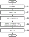
图3是表示第一实施方式的干扰推定处理的一个例子的图。FIG. 3 is a diagram showing an example of interference estimation processing in the first embodiment.
图4是表示第一实施方式的处理的更新定时的一个例子的图。FIG. 4 is a diagram showing an example of update timing of processing in the first embodiment.
图5是表示第二实施方式的干扰推定装置的主要部分的功能构成的一个例子的图。5 is a diagram showing an example of a functional configuration of a main part of an interference estimation device according to a second embodiment.
图6是表示第二实施方式的干扰推定处理的一个例子的图。FIG. 6 is a diagram showing an example of interference estimation processing in the second embodiment.
图7是表示第三实施方式的干扰推定装置的主要部分的功能构成的一个例子的图。FIG. 7 is a diagram showing an example of a functional configuration of a main part of an interference estimation device according to a third embodiment.
图8是表示第三实施方式的干扰推定处理的一个例子的图。FIG. 8 is a diagram showing an example of interference estimation processing according to the third embodiment.
图9是表示第四实施方式的干扰推定装置的主要部分的功能构成的一个例子的图。FIG. 9 is a diagram showing an example of a functional configuration of a main part of an interference estimation device according to a fourth embodiment.
图10是表示第四实施方式的干扰的产生时刻及其影响表现于测量值为止的时间差的一个例子的图。FIG. 10 is a diagram showing an example of the time difference between the generation time of the disturbance and its influence appearing in the measured value in the fourth embodiment.
图11是表示第四实施方式的干扰推定处理的一个例子的图。FIG. 11 is a diagram showing an example of interference estimation processing in the fourth embodiment.
图12是表示第五实施方式的干扰推定装置的主要部分的功能构成的一个例子的图。FIG. 12 is a diagram showing an example of a functional configuration of a main part of an interference estimation device according to a fifth embodiment.
图13是表示第五实施方式的干扰推定处理的一个例子的图。FIG. 13 is a diagram showing an example of interference estimation processing according to the fifth embodiment.
图14是表示第六实施方式的干扰推定装置的主要部分的功能构成的一个例子的图。FIG. 14 is a diagram showing an example of a functional configuration of a main part of an interference estimation device according to a sixth embodiment.
图15是表示各实施方式的干扰推定装置的硬件构成的一个例子的图。FIG. 15 is a diagram showing an example of a hardware configuration of an interference estimation device according to each embodiment.
具体实施方式detailed description
以下,参照附图对实施方式的干扰推定装置进行说明。在以下的说明中,对具有相同或者类似的功能的构成标注相同的附图标记。并且,有时会省略这些构成的重复的说明。“XX或YY”并不限于XX和YY中的任一方的情况,也可以包括XX和YY双方的情况。这在选择性要素为三个以上的情况下也同样。“XX”和“YY”是任意的要素(例如任意的信息)。Hereinafter, an interference estimation device according to an embodiment will be described with reference to the drawings. In the following description, components having the same or similar functions are denoted by the same reference numerals. Also, overlapping descriptions of these configurations may be omitted. "XX or YY" is not limited to any one of XX and YY, and may include both XX and YY. This is also the case when there are three or more optional elements. "XX" and "YY" are arbitrary elements (for example, arbitrary information).
<第一实施方式><First Embodiment>
(构成)(constitute)
图1是各实施方式的控制系统的概略图。FIG. 1 is a schematic diagram of a control system in each embodiment.
控制系统100包括:干扰推定装置10、控制装置20以及控制对象30。干扰推定装置10在控制对象30的控制时,推定对其控制量造成影响的干扰。干扰推定装置10具备:获取部11、推定部12以及输出部13。获取部11获取设于控制对象30的传感器测量的测量值。当在控制对象30中产生干扰时,其干扰会表现为获取部11获取的测量值的变动。推定部12使用获取部11获取到的测量值来推定控制量产生的干扰q的大小。输出部13向控制装置20输出干扰q的推定值(以下,记载为干扰q或者推定值q)。The
控制装置20从干扰推定装置10获取干扰q,并获取控制对象30的传感器测量出的测量值。控制装置20根据干扰q和测量值对控制对象30进行控制。控制对象30是指例如垃圾焚烧炉、发电设备、化学设备等各种设备,船舶、燃气轮机、蒸汽轮机、压缩机等各种机械等。以下,列举垃圾焚烧炉作为控制对象30的一个例子对本公开的干扰推定处理进行说明,但各实施方式的应用对象不限于垃圾焚烧炉。The
控制装置20获取的测量值包括控制量。控制装置20例如以控制量固定的方式对控制对象30进行控制。例如,理想的是,在垃圾焚烧炉中以使产生的蒸汽的流量固定的方式进行运转。若产生的蒸汽流量固定,则作为焚烧炉能够以最大能力持续地产生蒸汽,因此能使垃圾的焚烧量,即处理量和基于发电的售电收入最大化。然而,从市中回收的垃圾多种多样,例如,即使在时间上以相同的比例向炉供给垃圾,也无法使蒸汽流量固定。在专利文献1的技术中,测量垃圾的水分,在专利文献2的技术中,推定垃圾的每单位质量的发热量并推定炉的发热量的变动原因,用于废弃物、燃烧空气的调节。蒸汽流量等成为控制目的的变量通常被称为控制量。并且,使包括控制量的控制对象的测量值违反意图地变动的情况通常被称为干扰。在垃圾焚烧炉中,垃圾中的水分的变动、垃圾的每单位质量的发热量的变动为代表性的干扰。而且,若宏观地理解这些干扰,则炉整体的发热量的变动也为干扰。专利文献1、2中记载的技术均为基于与垃圾焚烧炉相关的热学知识来推定与燃烧速度的变动相关的特定的干扰的技术。与此相对,就本实施方式的技术而言,即使没有关于控制对象的例如热学那样的现有知识,也能够推定干扰q。具体而言,根据从设于控制对象的传感器得到的测量值来推定主导性的干扰。以下,以垃圾焚烧炉为例,对推定部12的干扰q的推定流程进行说明。The measured values acquired by the
图2是表示第一实施方式的干扰推定装置的主要部分的功能构成的一个例子的图。FIG. 2 is a diagram showing an example of a functional configuration of a main part of the interference estimation device according to the first embodiment.
图2中示出干扰推定装置10中的推定部12的主要部分的构成。推定部12具备:单元121,构成以控制对象30的传感器测量出的测量值作为要素的m行1列的测量向量y;单元122,计算测量向量y的方差协方差矩阵;单元123,对方差协方差矩阵进行奇异值分解来计算最大奇异值的奇异向量;以及单元124,基于最大奇异值的奇异向量来推定控制对象30的干扰q。FIG. 2 shows the configuration of main parts of the
(干扰的推定流程)(Flow of Estimation of Interference)
由q∈R1表示干扰。在垃圾焚烧炉中,作为干扰q的主导性的干扰是燃烧速度。当干扰q变动时,测量值y∈Rm也变动。如算式(1)所示,用一次式对两者的变动进行近似。Interference is represented by q ∈ R 1 . In the waste incinerator, the dominant disturbance as the disturbance q is the burning speed. When the disturbance q changes, the measured value y∈R m also changes. As shown in the formula (1), the fluctuations of both are approximated by a linear formula.
y=c1×q……(1)y=c 1 ×q...(1)
算式(1)的c1为m行1列的系数向量。c1表示干扰q增加时的测量向量y的响应。在垃圾焚烧炉中,若燃烧速度增加,则蒸汽流量增加,燃烧室温度升高,排气的氧气浓度减少。c1是对增加、减少进行定量化的系数向量,如以下方式确定其值。首先,如算式(2)那样计算以测量值作为列要素的测量向量y的方差协方差矩阵Q0∈Rm×m。算式(2)的Var为方差的记号。c 1 in the formula (1) is a coefficient vector with m rows and 1 column. c 1 represents the response of the measurement vector y when the disturbance q increases. In the waste incinerator, if the combustion speed increases, the steam flow rate increases, the temperature of the combustion chamber increases, and the oxygen concentration of the exhaust gas decreases. c1 is a coefficient vector for quantifying increase and decrease, and its value is determined as follows. First, the variance covariance matrix Q 0 ∈R m×m of the measurement vector y having measured values as column elements is calculated as in formula (2). Var in the formula (2) is a sign of variance.
Q0=Var(y)……(2)Q 0 =Var(y)...(2)
接着,对方差协方差矩阵Q0进行奇异值分解(Singular Value Decomposition,SVD),求出算式(3)的奇异向量ui(i=1,2,……,m)∈Rm和奇异值σ2 i(i=1,2,……,m)∈R+。奇异值在此按照奇异值分解的惯例,按照大小顺序进行排序。即σ2 1为最大奇异值,σ2 m为最小奇异值。右肩的记号T表示矩阵的转置。Next, perform singular value decomposition (Singular Value Decomposition, SVD) on the variance covariance matrix Q 0 to obtain the singular vector u i (i=1, 2, ..., m)∈R m and the singular value σ 2 i (i=1, 2, . . . , m)∈R + . Here, the singular values are sorted in order of magnitude according to the convention of singular value decomposition. That is, σ 2 1 is the largest singular value, and σ 2 m is the smallest singular value. The notation T on the right shoulder indicates the transpose of the matrix.
[数式1][Formula 1]

接着,设为存在干扰ρi(i=1,2,……,m)∈R1,如算式(4)那样,由奇异向量u和未知的干扰ρ表示测量向量y的变动。未知的干扰ρ的要素是线性独立的,即若i≠j,则Cov(ρi,ρj)=0。Cov为协方差的记号。对测量向量y的方差协方差矩阵Q0进行奇异值分解时可知u的值,因此能根据测量向量y计算未知的干扰ρ的值。Next, assuming that there is disturbance ρ i (i=1, 2, . . . , m)∈R 1 , the variation of the measurement vector y is represented by the singular vector u and the unknown disturbance ρ as in Equation (4). The elements of the unknown disturbance ρ are linearly independent, that is, if i≠j, then Cov(ρ i , ρ j )=0. Cov is the notation for covariance. The value of u can be known when performing singular value decomposition on the variance covariance matrix Q 0 of the measurement vector y, so the value of the unknown disturbance ρ can be calculated according to the measurement vector y.
[数式2][Formula 2]

由于方差协方差矩阵Q0的对称性,奇异向量u具有算式(5)的性质。Due to the symmetry of the variance covariance matrix Q 0 , the singular vector u has the property of formula (5).
[数式3][Formula 3]

因此,能在算式(4)的两边从左起乘以uT而显式地(explicitly)定义干扰ρ。Therefore, disturbance ρ can be defined explicitly (explicitly) by multiplying both sides of the formula (4) by u T from the left.
[数式4][Formula 4]

计算干扰ρ的方差协方差矩阵时得到算式(7)。Equation (7) is obtained when calculating the variance covariance matrix of interference ρ.
[数式5][Formula 5]

作为未知的干扰的第一要素的ρ1的方差如算式(7)所示,为最大奇异值σ1 2。因此,可以说测量向量y的方差起因于ρ1的分量最大。这是因为,根据奇异值的性质,成立以下算式(8),The variance of ρ 1 , which is the first element of the unknown disturbance, is the largest singular value σ 1 2 as shown in formula (7). Therefore, it can be said that the variance of the measurement vector y is due to the largest component of ρ1. This is because, according to the nature of the singular value, the following formula (8) is established,
Var(y1)+Var(y2)+……+Var(ym)=Var(y 1 )+Var(y 2 )+...+Var(y m )=
σ1 2+σ2 2+……+σm 2……(8),σ 1 2 + σ 2 2 + ... + σ m 2 ... (8),
特别是当σ1 2>>σ2 2+σ3 2+……+σm 2时,如以下算式(8A)那样进行近似,测量向量y的变动被ρ1主导。In particular, when σ 1 2 >> σ 2 2 + σ 3 2 + .
[数式6][Formula 6]

从算式(6)取出与ρ1相关的部分,得到算式(9)作为干扰q的推定式。 The part related to ρ1 is taken out from formula (6), and formula (9) is obtained as the estimation formula of interference q.
[数式7][Formula 7]

在垃圾焚烧炉的例子中,可知作为干扰q,燃烧速度的变动是主导性的。当获取部11获取测量值y,推定部12根据上述的流程,通过算式(9)推定主导性的干扰q时,该干扰q为燃烧速度的变动。输出部13将干扰q向控制装置20输出。控制装置20将干扰q视为燃烧速度的变动,以将其抵消的方式调整燃烧空气、垃圾供给。由此,能使蒸汽流量固定地使垃圾焚烧炉运转。不限于垃圾焚烧炉,无论是何种控制对象,都能对主导性的干扰进行推测。例如,在船舶的自动转向中潮流为主导性的干扰,在汽车的速度控制中路面的坡度等为主导性的干扰。这些是从经验得到的见解,而不是运动方程式等分析性的单元。In the example of a waste incinerator, it can be seen that the fluctuation of the combustion rate is dominant as the disturbance q. When the acquiring
(动作)(action)
将上述的流程示于图3。图3是表示第一实施方式的干扰推定处理的一个例子的图。首先,获取部11获取设于垃圾焚烧炉的传感器测量出的蒸汽流量、燃烧室温度、排气的氧气浓度等测量值(步骤S1)。推定部12的单元121使用获取部11获取的测量值来构成测量向量y(步骤S2)。例如,单元121构成以蒸汽流量、燃烧室温度、排气的氧气浓度的各测量值作为要素的测量向量y。接着,推定部12的单元122根据算式(2)计算方差协方差矩阵Q0(步骤S3)。接着,推定部12的单元123根据算式(3)对方差协方差矩阵进行奇异值分解来计算最大奇异值的奇异向量(步骤S4)。接着,推定部12的单元124根据算式(9)来推定干扰q(步骤S5)。推定部12向控制装置20输出干扰q。The above-mentioned flow is shown in FIG. 3 . FIG. 3 is a diagram showing an example of interference estimation processing in the first embodiment. First, the acquiring
将上述的干扰推定处理中的测量向量y、干扰q、Q0、u1的更新定时的关系示于图4。例如,测量向量y以新的测量值到达干扰推定装置10的周期TA进行更新,相应地干扰q也以周期TA进行更新。此外,基于算式(2)的方差协方差矩阵Q0、基于算式(3)的奇异值分解的u1的更新以周期TB进行更新。奇异值向量u1根据方差协方差矩阵来决定值,因此以更新方差协方差矩阵Q0的周期TB进行计算。更新周期基于对象的特性来确定,但通常为TA<<TB。作为特殊的情况,若对象的特性固定,则奇异值向量u1也可以固定为事先决定的值。FIG. 4 shows the relationship between the update timings of the measurement vector y, the disturbance q, Q 0 , and u 1 in the disturbance estimation process described above. For example, the measurement vector y is updated with a period T A when a new measurement value arrives at the disturbance estimation device 10 , and the disturbance q is also updated with a period T A accordingly . In addition, updating of the variance covariance matrix Q 0 based on the formula (2) and u 1 based on the singular value decomposition of the formula (3) is performed at a cycle T B . Since the value of the singular value vector u 1 is determined according to the variance-covariance matrix , calculation is performed at a cycle TB of updating the variance-covariance matrix Q 0 . The update period is determined based on the characteristics of the object, but is usually T A << T B . As a special case, if the characteristics of the object are fixed, the singular value vector u 1 can also be fixed to a predetermined value.
根据本实施方式,能基于控制对象30中测量出的测量值,推定影响控制量的干扰q。大多情况下,控制对象30的传感器是为了对控制量、影响控制量的物理量进行测量而设置的,因此无需追加新的传感器,能使用已设的传感器的测量值来推定干扰q。此外,如图4所举例示出的那样,能以得到测量向量y的周期TA推定基于最新的测量值的及时的干扰q。此外,只要执行设于控制对象30的传感器进行的测量值的获取和上述的流程即可,因此能够不取决于控制对象30的特性而广泛应用于各种控制对象30的干扰推定。According to the present embodiment, the disturbance q that affects the control variable can be estimated based on the measured value measured in the controlled
<第二实施方式><Second Embodiment>
使用图5、图6对第二实施方式的干扰推定装置进行说明。The interference estimation device according to the second embodiment will be described with reference to FIGS. 5 and 6 .
在第一实施方式中,以事先明确了主导性的干扰(例如,燃烧速度)为前提。在垃圾焚烧炉中,已知燃烧速度为主导性的干扰,因此由算式(9)计算出的干扰q为燃烧速度的变动,基于燃烧速度的变动调节了燃烧空气、垃圾的供给量。在第二实施方式中,将干扰换算为控制量的变动来进行推定。由此,即使在事先未知主导性的干扰的情况下,也能应用与第一实施方式相同的方法。例如,在垃圾焚烧炉的情况下,控制量是指蒸汽流量,将干扰换算为控制量的变动来进行推定是指将燃烧速度的变动换算为其引起的蒸汽流量的变动来进行推定。通过换算为控制量的变动来进行推定,可得到如下优点:即使没有燃烧速度的变动为主导性的干扰这样的知识,也能推定干扰q,不仅如此,在控制垃圾焚烧炉的基础上,无需将干扰q的大小(燃烧速度)换算为作为控制量的蒸汽流量,能以蒸汽流量的状态处理并挪用于控制。In the first embodiment, it is assumed that the dominant disturbance (for example, the combustion rate) is clarified in advance. In the waste incinerator, it is known that the combustion rate is the dominant disturbance, so the disturbance q calculated by the formula (9) is the change of the combustion rate, and the supply of combustion air and garbage is adjusted based on the change of the combustion rate. In the second embodiment, the estimation is performed by converting the disturbance into a change in the control amount. Thus, even when the dominant interference is not known in advance, the same method as that of the first embodiment can be applied. For example, in the case of a waste incinerator, the control amount refers to the steam flow rate, and estimating by converting a disturbance into a change in the control amount means converting a change in the combustion rate into a change in the steam flow rate caused by it. Estimated by converting it into the fluctuation of the control quantity, the following advantages can be obtained: even if there is no knowledge that the fluctuation of the combustion rate is the dominant disturbance, the disturbance q can be estimated. The magnitude of the disturbance q (combustion speed) is converted into the steam flow rate as the control amount, and can be handled in the state of the steam flow rate and used for control.
(构成)(constitute)
图5是表示第二实施方式的干扰推定装置的主要部分的功能构成的一个例子的图。5 is a diagram showing an example of a functional configuration of a main part of an interference estimation device according to a second embodiment.
第二实施方式的干扰推定装置10A具备推定部12A来代替推定部12。第二实施方式的获取部11获取的测量值包括控制量。以下,将控制量配置为测量向量y的第一要素来进行说明。An
第二实施方式的推定部12A具备单元125来代替单元124,所述单元125基于最大奇异值的奇异向量将施加于对象物的干扰推定为控制量的变动。推定部12A与第一实施方式同样地,由算式(2)计算测量向量y的方差协方差矩阵Q0,如算式(3)那样对方差协方差矩阵Q0进行奇异值分解。然后,推定部12A计算奇异值向量ui(i=1,2,……,m)和奇异值σ2 i(i=1,2,……,m)。取出算式(6)的第一行而得到的为算式(6A)。The estimating
[数式8][Formula 8]

此处,u1,j(j=1,2,……,m)为关于最大奇异值的奇异值向量u1的第j要素。若对应于第一要素(控制量)的最大奇异值为主导性的,即若σ2 1>>σ2 2+σ2 3+……+σ2 m,则测量向量y如算式(10A)那样进行近似。Here, u 1,j (j=1, 2, . . . , m) is the jth element of the singular value vector u 1 with respect to the largest singular value. If the largest singular value corresponding to the first element (control quantity) is dominant, that is, if σ 2 1 >>σ 2 2 +σ 2 3 +…+σ 2 m , then the measurement vector y is as in formula (10A) Approximate like that.
[数式9][Formula 9]

算式(6A)的ξ通过主导性的ρ1如算式(11)所示。ξ of the formula (6A) is shown in the formula (11) through the dominant ρ 1 .
[数式10][Formula 10]

此处ξ|ρ1表示将ρ1作为输入条件时的ξ。Here ξ| ρ1 represents ξ when ρ1 is used as the input condition.
同样地,控制量通过ρ1如下所示。Likewise, the control amount via ρ1 is as follows.
y1|ρ1=u11ρ1……(12)y 1 |ρ 1 =u 11 ρ 1 ...(12)
此处y1|ρ1表示将ρ1作为输入条件时的y1。根据算式(12)可知ξ的值时,将换算为控制量的变动的干扰记为qy1|ξ,其由以下算式(13)所示。Here, y 1 |ρ 1 represents y 1 when ρ 1 is used as an input condition. When the value of ξ is known from Equation (12), the disturbance converted into the fluctuation of the control variable is denoted as q y1 |ξ, which is expressed by the following Equation (13).
[数式11][Formula 11]

(动作)(action)
将上述的流程示于图6。图6是表示第二实施方式的干扰推定处理的一个例子的图。首先,获取部11获取设于垃圾焚烧炉的传感器测量出的测量值(步骤S1)。测量值包括控制量。接着,推定部12A的单元121构成测量向量y(步骤S2)。单元121将控制量作为第一要素,构成测量向量y。接着,推定部12A的单元122根据算式(2)计算方差协方差矩阵Q0(步骤S3)。接着,推定部12A的单元123根据算式(3)对方差协方差矩阵进行奇异值分解来计算最大奇异值的奇异向量(步骤S4)。接着,推定部12A的单元125根据算式(13)推定换算为控制量的变动的干扰qy1|ξ(步骤S6)。推定部12A向控制装置20输出干扰qy1|ξ。The above-mentioned flow is shown in FIG. 6 . FIG. 6 is a diagram showing an example of interference estimation processing in the second embodiment. First, the
根据本实施方式,除了第一实施方式的效果以外,即使没有关于干扰的知识,也能基于控制对象30中测量出的测量值,计算将干扰q换算为控制量的变动而得到的推定值qy1|ξ。例如,与第一实施方式同样地,测量向量y和干扰qy1|ξ以周期TA进行更新。另一方面,奇异值向量u1根据方差协方差矩阵Q0来决定值,因此以更新方差协方差矩阵Q0的周期TB进行计算。此外,若对象的特性固定,则奇异值向量u1也可以固定为事先决定的值。According to this embodiment, in addition to the effects of the first embodiment, even without knowledge about the disturbance, it is possible to calculate the estimated value q obtained by converting the disturbance q into the fluctuation of the control amount based on the measured value measured in the controlled
<第三实施方式><Third Embodiment>
使用图7、图8对第三实施方式的干扰推定装置进行说明。An interference estimation device according to a third embodiment will be described with reference to FIGS. 7 and 8 .
在第三实施方式中,比较将干扰推定为控制量的变动的推定值qy1|ξ与控制量的实测值y1来判定干扰推定的精度。若精度差,则控制装置20取消抵消干扰的调节。在垃圾焚烧炉的例子中,若推定出的蒸汽流量的变动与实际的蒸汽流量之差小,则基于推定出的蒸汽流量的变动来调节燃烧空气、垃圾供给而抵消变动。另一方面,若推定出的蒸汽流量的变动与实际的蒸汽流量之差大,则取消调节。In the third embodiment, the accuracy of the disturbance estimation is determined by comparing the estimated value q y1 |ξ, which estimates the disturbance as a fluctuation of the control amount, and the actual measurement value y 1 of the control amount. If the accuracy is poor, the
(构成)(constitute)
图7是表示第三实施方式的干扰推定装置的主要部分的功能构成的一个例子的图。FIG. 7 is a diagram showing an example of a functional configuration of a main part of an interference estimation device according to a third embodiment.
第三实施方式的干扰推定装置10B具备推定部12B来代替推定部12。推定部12B通过在第二实施方式中说明的处理来计算推定值qy1|ξ,判定推定值qy1|ξ的精度。推定部12B除了第二实施方式的推定部12A的构成以外,还具备:单元126,计算推定出的控制量的变动与实际的控制量的误差;单元127,对计算出的误差的方差进行计算;以及单元128,根据误差的方差判定干扰推定的可靠性。第二实施方式的获取部11获取的测量值包括控制量。以下,将控制量配置为测量向量y的第一要素来进行说明。第三实施方式的输出部13除了推定值qy1|ξ以外,还输出干扰推定精度的判定结果(调整限制指令)。The
推定部12B获取推定出的控制量(例如,蒸汽流量)的变动的推定值qy1|ξ和实际的控制量y1,由以下算式(14)计算变动的推定值qy1|ξ与控制量y1之差的方差。The estimating
J=Var(y1-qy1|ξ)……(14)J=Var(y 1 -q y1 |ξ)...(14)
若方差J比预先设定的阈值小,则推定部12B对调整限制指令设定关闭,若方差J比预先设定的阈值大,则推定部12B对调整限制指令设定打开。输出部13向控制装置20输出推定部12B计算出的推定值qy1|ξ和调整限制指令。若调整限制指令为关闭(方差J比阈值小),则控制装置20实施抵消干扰的调节。例如,在垃圾焚烧炉的情况下,以抑制蒸汽流量的变动(推定值qy1|ξ)的方式调整垃圾供给、燃烧空气的供给量。若调整限制指令为打开(方差J比阈值大),则不实施抵消干扰的调整。If the variance J is smaller than a preset threshold, the
(动作)(action)
将上述的流程示于图8。图8是表示第三实施方式的干扰推定处理的一个例子的图。首先,通过在第二实施方式中说明的处理,推定部12B推定换算为控制量的变动的干扰qy1|ξ(步骤S10)。接着,单元126计算推定的控制量的变动即干扰qy1|ξ与控制量y1的误差(步骤S11)。接着,单元127计算步骤S11中计算出的误差的方差J(步骤S12)。接着,单元128基于步骤S12中计算出的误差的方差J,判定干扰qy1|ξ的推定的可靠性(步骤S13)。在方差J比规定的阈值大的情况下,单元128判定为推定不可靠,在方差J比规定的阈值小的情况下,单元128判定为推定可靠。如图7所示,在该判定中也可以设有迟滞宽度。通过设置迟滞宽度,能吸收控制量y1的测量误差、变动,进行稳定的控制。单元128在判定为推定不可靠时,对调整限制指令设定打开,单元128在判定为推定可靠时,对调整限制指令设定关闭。推定部12B向控制装置20输出干扰的推定值qy1|ξ和调整限制指令(打开或关闭)(步骤S14)。The above-mentioned flow is shown in FIG. 8 . FIG. 8 is a diagram showing an example of interference estimation processing according to the third embodiment. First, the estimating
在步骤S13中,在调整限制指令为打开的状况持续的情况下,推定部12B也可以进行提高使用图4进行说明的Q0、u1的更新频率等,尝试提高精度。在即使如此精度也没有提高的情况下,也可以重新选定作为在推定值qy1|ξ的计算中使用的测量向量y的第二要素以下而使用的测量值。In step S13, when the condition that the adjustment restriction command is ON continues, the estimating
根据本实施方式,除了第二实施方式的效果以外,还能在确认干扰推定值qy1|ξ的精度的同时,进行控制对象30的控制。此外,通过将基于调整限制指令的值在基于干扰的推定值qy1|ξ的调整的执行和停止之间自动地进行切换的功能嵌入控制装置20,能确保控制装置20的控制精度。According to this embodiment, in addition to the effects of the second embodiment, it is possible to control the controlled
<第四实施方式><Fourth Embodiment>
使用图9~图11对第四实施方式的干扰推定装置10C进行说明。An interference estimation device 10C according to a fourth embodiment will be described with reference to FIGS. 9 to 11 .
从干扰发生起至成为控制量、测量值的变动而表现之前,通常存在时间滞后。例如,在垃圾焚烧炉中,作为干扰而燃烧速度变化后,其影响表现于炉内的温度花费例如10秒的时间,以蒸汽流量的变动的形式表现花费例如300秒的时间。即,例如即使在时刻t燃烧速度变化,其影响表现于炉内温度的时刻为t+10,表现于蒸汽流量的变动的时刻为t+300。因此,在该情况下,关于燃烧速度的变动,炉内温度与蒸汽流量存在290秒的响应的时间差。若已知这一点,则应该对两者附加290秒的时间差来构成测量向量y。例如,若设为测量向量y包括蒸汽流量和炉内温度,则时刻t的测量向量的要素使用时刻t的蒸汽流量和时刻t-290的炉内温度。在滞后时间的值不确定的情况下,可以改变滞后时间的值而设定多个。例如,在前述的例子中,测量向量y的要素设为时刻t的蒸汽流量和时刻t-290的炉内温度。还可以在其中加入时刻t-350的炉内温度、时刻t-320的炉内温度、时刻t-260的炉内温度等作为测量向量y的要素。There is usually a time lag between the occurrence of a disturbance and its expression as a change in the control variable or measured value. For example, in a waste incinerator, after the combustion rate changes as a disturbance, it takes, for example, 10 seconds for its influence to appear on the temperature inside the furnace, and it takes, for example, 300 seconds for it to appear as a change in the steam flow rate. That is, for example, even if the combustion rate changes at time t, the time when the influence appears on the furnace temperature is t+10, and the time when the steam flow rate is fluctuated is t+300. Therefore, in this case, there is a response time difference of 290 seconds between the temperature in the furnace and the flow rate of steam with respect to the fluctuation of the combustion rate. If this is known, a time difference of 290 seconds should be added to the two to form the measurement vector y. For example, if the measurement vector y includes the steam flow rate and the furnace temperature, the steam flow rate at time t and the furnace temperature at time t-290 are used as elements of the measurement vector at time t. When the value of the lag time is uncertain, it is possible to set a plurality of lag time values by changing them. For example, in the above example, the elements of the measurement vector y are the steam flow rate at time t and the furnace temperature at time t-290. The temperature in the furnace at time t-350, the temperature in the furnace at time t-320, the temperature in the furnace at time t-260, etc. may also be added as elements of the measurement vector y.
图9是表示第四实施方式的干扰推定装置的主要部分的功能构成的一个例子的图。FIG. 9 is a diagram showing an example of a functional configuration of a main part of an interference estimation device according to a fourth embodiment.
图9中示出与第二实施方式组合的情况的第四实施方式的构成。第四实施方式的推定部12C除了第二实施方式的构成以外,还具备滞后时间校正单元129。针对测量向量y的各要素,滞后时间校正单元129将过去测量出的测量值与滞后时间建立对应来进行存储。例如,在测量向量y包括蒸汽流量和炉内温度的情况下,滞后时间校正单元129将在时刻t通过获取部11获取到的290秒前的炉内温度的测量值与炉内温度比蒸汽流量滞后290秒的情况建立对应来进行存储。滞后时间校正单元129获取测量向量y,根据存储于内部的滞后时间的值来校正测量向量的各个要素的滞后时间,输出滞后时间校正后的测量向量y~。在第四实施方式中,推定部12C基于滞后时间校正后的测量向量y~推定干扰来代替测量向量y。FIG. 9 shows the configuration of the fourth embodiment in combination with the second embodiment. The
使用图10对时间校正进行进一步具体说明。图10是表示干扰的产生时刻及其影响表现于测量值为止的时间差的一个例子的图。测量向量y存在m个要素,若将每个要素的滞后时间设为τi(i=1,2,…,m),则从干扰产生起至在测量向量y的要素中表现出响应为止的时间如图10所示。在此,为了简化说明,设为测量向量y~的要素按照滞后时间的大的顺序排列。控制量为垃圾焚烧炉等设备的最终的输出,因此通常滞后时间在测量向量y~的要素中为最大。由于是用于补偿控制量的变动的干扰推定,因此将响应比控制量慢的要素用于干扰的推定是没有意义的。因此,在测量向量y的要素中,控制量的滞后时间当然最大。考虑在时刻t计算算式(6A)的ξ。如图10所示,用于ξ的计算的是时刻t以前的信息。另一方面,需要说明的是,对控制量y1表现干扰的影响的是τΔ=τ2-τ1后。滞后时间校正后的测量向量y~能使用滞后时间如以下算式(15)那样表示。The time correction will be described in more detail using FIG. 10 . FIG. 10 is a diagram showing an example of a time difference between the generation time of a disturbance and its influence appearing in a measured value. There are m elements in the measurement vector y, and if the lag time of each element is set as τ i (i=1, 2, ..., m), the time from the generation of disturbance to the response in the elements of the measurement vector y The timing is shown in Figure 10. Here, to simplify the description, it is assumed that the elements of the measurement vector y to are arranged in order of greater lag time. Since the control amount is the final output of equipment such as a waste incinerator, the lag time is usually the largest among the elements of the measurement vector y˜ . Since it is a disturbance estimation for compensating for fluctuations in the control quantity, it is meaningless to use an element whose response is slower than the control quantity for disturbance estimation. Therefore, among the elements of the measurement vector y, the lag time of the control variable is of course the largest. Consider calculation of ξ in equation (6A) at time t. As shown in FIG. 10, information before time t is used for the calculation of ξ. On the other hand, it should be noted that the influence of disturbance on the control variable y 1 is after τΔ=τ 2 −τ 1 . The measurement vector y after the lag time correction can be expressed as the following formula (15 ) using the lag time.
[数式12][Formula 12]

使用该滞后时间校正后的测量向量y~求出方差协方差矩阵Q0,进而计算其奇异向量u。在时刻t时间点{y~ 2,y~ 3,……,y~ m}为当前值或者过去值,因此推定部12C使用它们通过算式(11)计算ξ|ρ1,使用算式(13)计算干扰qy^1|ξ。干扰qy^1|ξ为在时刻t的时间点预测的时刻t+τΔ的控制量(例如,蒸汽流量)的变动的预测。由于将来的值已知,因此若显示于垃圾焚烧炉的运转操作盘等上,则有助于运转操作。The variance - covariance matrix Q 0 is obtained by using the measured vector y after the lag time correction, and then its singular vector u is calculated. At time t, time points {y ~ 2 , y ~ 3 , ..., y ~ m } are current values or past values, so the
(动作)(action)
将上述的流程示于图11。图11是表示第四实施方式的干扰推定处理的一个例子的图。首先,获取部11获取设于垃圾焚烧炉的传感器测量出的蒸汽流量、燃烧室温度、排气的氧气浓度等测量值(步骤S1)。接着,推定部12C的单元121构成测量向量y(步骤S2)。接着,推定部12C的滞后时间校正单元129获取测量向量y,输出校正了各要素的滞后时间的、滞后时间校正后的测量向量y~(步骤S7)。以后与第二实施方式相同。即,推定部12C的单元122根据算式(2)计算方差协方差矩阵Q0(步骤S3)。接着,推定部12C的单元123根据算式(3)对方差协方差矩阵进行奇异值分解来计算最大奇异值的奇异向量(步骤S4)。接着,推定部12C的单元125根据算式(13)推定换算为控制量的变动的干扰qy^1|ξ(步骤S6)。推定部12C将干扰的推定值(预测值)qy^1|ξ向控制装置20输出。The above-mentioned flow is shown in FIG. 11 . FIG. 11 is a diagram showing an example of interference estimation processing in the fourth embodiment. First, the acquiring
根据第四实施方式,除了第二实施方式的效果以外,由于对在各个测量值中直至表现出干扰的影响为止的滞后时间进行校正,因此能提高干扰推定精度。第四实施方式不仅能与第二实施方式组合,还能与第一实施方式、第三实施方式组合。此外,在与第二实施方式、第三实施方式组合的情况下,根据第四实施方式,能预测将来的控制量。According to the fourth embodiment, in addition to the effects of the second embodiment, since the lag time until the influence of the disturbance appears in each measurement value is corrected, the disturbance estimation accuracy can be improved. The fourth embodiment can be combined not only with the second embodiment but also with the first embodiment and the third embodiment. Moreover, when combining with 2nd Embodiment and 3rd Embodiment, according to 4th Embodiment, future control amount can be predicted.
<第五实施方式><Fifth Embodiment>
使用图12~图13对第五实施方式的干扰推定装置10D进行说明。An
在第四实施方式中,推定了由干扰引起的控制量的变动的预测值。在第五实施方式中,组合第四实施方式与第三实施方式来判定预测的精度。若已知预测精度差,则控制装置20取消抵消干扰的调节,以使误差不会造成不良影响。例如,在垃圾焚烧炉的例子中,若预测出的蒸汽流量的变动与实际的蒸汽流量之差小,则控制装置20基于预测出的蒸汽流量的变动调节燃烧空气、垃圾供给来抵消变动。另一方面,若预测出的蒸汽流量的变动与实际的蒸汽流量之差大,则控制装置20取消调节。In the fourth embodiment, the predicted value of the fluctuation of the control amount due to disturbance is estimated. In the fifth embodiment, the prediction accuracy is determined by combining the fourth embodiment and the third embodiment. If it is known that the prediction accuracy is poor, the
(构成)(constitute)
图12是表示第五实施方式的干扰推定装置的主要部分的功能构成的一个例子的图。FIG. 12 is a diagram showing an example of a functional configuration of a main part of an interference estimation device according to a fifth embodiment.
第五实施方式的干扰推定装置10D具备推定部12D来代替推定部12。推定部12D通过下述的类似于第四实施方式的说明的处理来计算推定值qy^1|ξ,基于与实际的控制量(例如,蒸汽流量)y1之差的方差判定推定值qy^1|ξ的精度。推定部12D除了第四实施方式的推定部12C的构成和第三实施方式的单元126~128以外,还具备根据控制量的变动来推定控制量的单元130,该控制量的变动是基于直至干扰的影响表现于控制量为止的滞后时间和干扰的预测值的控制量的变动。第二实施方式的获取部11获取的测量值包括控制量。第五实施方式的输出部13输出控制量的预测值y^ 1和控制量的预测值的预测精度的判定结果(调整限制指令)。An
在第五实施方式中,如算式(16)那样构成在第四实施方式中说明的滞后时间校正后的测量向量。In the fifth embodiment, the lag time-corrected measurement vector described in the fourth embodiment is configured as in the formula (16).
[数式13][Formula 13]

测量向量z~对测量向量y~的第二要素追加了控制量y1(t)。求出测量向量z~的方差协方差矩阵Q0,进而计算其奇异向量u。在时刻t,{z~ 2,z~ 3,…,z~ m+1}为当前值或过去值,因此使用它们并使用算式(17)来计算ξ。In the measurement vector z ˜ , the control amount y 1 (t) is added to the second element of the measurement vector y ˜ . Calculate the variance covariance matrix Q 0 of the measurement vector z ~ , and then calculate its singular vector u. At time t, {z ~ 2 , z ~ 3 , ..., z ~ m+1 } are current values or past values, so use them and calculate ξ using equation (17).
[数式14][Formula 14]

根据ξ,如算式(18)那样得到z~ 1即时刻t+y1的预测值。From ξ, the predicted value of z to 1 , that is, time t+y 1 is obtained as in formula (18).
[数式15][Formula 15]

干扰的预测值qz~1|ξ(t)为qy^1|ξ(t),为时刻t的控制量y1(t+τΔ)的预测值。由于y1(t+τΔ)为预测值,因此为了与实际的测量值进行区分而记为y^ 1(t+τΔ),若利用τΔ×预测值的时间导数对时刻t与时刻t+τΔ之间的预测值的增量进行近似,则导出算式(19)。The predicted value of disturbance q z~1 |ξ(t) is q y^1 |ξ(t), which is the predicted value of the control variable y 1 (t+τ Δ ) at time t. Since y 1 (t+τ Δ ) is the predicted value, it is recorded as y ^ 1 (t+τ Δ ) in order to distinguish it from the actual measured value. If the time derivative of τ Δ × predicted value is used to compare time t and time Approximating the increment of the predicted value between t +τΔ, the formula (19) is derived.
[数式16][Formula 16]

根据算式(19),如算式(20)那样得到表示预测值的时间变化的微分方程式。From the formula (19), a differential equation representing the temporal change of the predicted value is obtained as in the formula (20).
[数式17][Formula 17]

通过针对时间将算式(20)进行数值积分,基于干扰的预测值qy^1|ξ(t)可知当前时刻t的控制量的推定值y^1(t)。在实际的计算中,算式(20)能如以下算式(21)那样通过时间常数为τΔ、增益为1的一阶滞后滤波器来简便地运算。By numerically integrating the formula (20) with respect to time, the estimated value y^1(t) of the control amount at the current time t can be known based on the predicted value q y^1 |ξ(t) of the disturbance. In actual calculation, the formula (20) can be easily calculated by using a first-order lag filter with a time constant of τ Δ and a gain of 1 as in the following formula (21).
[数式18][Formula 18]

单元130通过算式(21),基于在时刻t预测时刻t+τΔ的干扰而得到的值qy^1|ξ(t)来推定时刻t的控制量。单元127根据通过算式(21)计算出的y^1(t)和实际的控制量的测量值y1(t),与第三实施方式同样地使用以下算式(22)来计算推定值与测量值(实测值)之差的方差。The
J=Var(y1(t)-y^1(t))……(22)J=Var(y 1 (t)-y^ 1 (t))...(22)
(动作)(action)
图13是表示第五实施方式的干扰推定处理的一个例子的图。FIG. 13 is a diagram showing an example of interference estimation processing according to the fifth embodiment.
通过在第四实施方式中说明的处理,推定部12D预测换算为时刻t+τΔ的控制量的干扰qy^1|ξ(步骤S20)。接着,单元130推定时刻t的控制量(步骤S21)。如上所述,干扰的预测值qy^1|ξ(t)表示时刻t+τΔ的控制量y^1(t+τΔ)。单元130通过算式(21)进行使时间倒转的计算,根据控制量y^1(t+τΔ)推定时刻t的控制量y^1(t)。接着,单元126计算时刻t的控制量的推定值与实际的控制量的误差(步骤S22)。接着,单元127计算步骤S22中计算出的误差的方差J(步骤S23)。单元127根据算式(22)计算方差J。接着,单元128基于在步骤S23中计算出的误差的方差J,判定控制量y^1(t)的推定的可靠性(步骤S24)。在方差J比规定的阈值大的情况下,单元128判定为推定不可靠,在方差J比规定的阈值小的情况下,单元128判定为推定可靠。如图12所示,在该判定中也可以设有迟滞宽度。通过设置迟滞宽度,能吸收控制量y1的测量误差、变动,进行稳定的控制。单元128在判定为推定不可靠时,对调整限制指令设定打开,单元128在判定为推定可靠时,对调整限制指令设定关闭。推定部12D向控制装置20输出控制量的预测值y^1和调整限制指令(打开或关闭)(步骤S25)。By the processing described in the fourth embodiment, the
在步骤S24中,在调整限制指令为打开的状况持续的情况下,推定部12D也可以进行提高使用图4进行说明的Q0、u1的更新频率等,尝试提高精度。在即使如此精度也没有提高的情况下,也可以重新选定作为在推定值qy^1|ξ的计算中使用的测量向量z~的第二要素以下而使用的测量值,或者重新设定其滞后时间。In step S24, when the condition that the adjustment restriction command is ON continues, the
根据本实施方式,除了第四实施方式的效果以外,还能在确认干扰预测值qy^1|ξ的预测精度的同时,进行控制对象30的控制。此外,通过将基于调整限制指令的值在基于干扰的预测值qy^1|ξ的调整的执行和停止之间自动地进行切换的功能嵌入控制装置20,能确保控制装置20的控制精度。According to this embodiment, in addition to the effect of the fourth embodiment, it is possible to control the controlled
<第六实施方式><Sixth Embodiment>
使用图14对第六实施方式的干扰推定装置10E进行说明。An
在本公开的干扰的推定中,奇异向量u1∈Rm是重要的。奇异向量u1按照预先指定的滞后时间{τ1,τ2,……,τm}每隔周期TB进行更新。奇异向量的值在每次更新时变化。虽然可以直接利用变化后的值,但例如若设为计算多个奇异向量并利用其中最优选的奇异向量的多数决方式,则期待干扰推定的可靠度比只有一个时提高。滞后时间也同样。此外,例如,考虑根据控制对象30的运转方式(启动时、额定运转时、低输出运转时),干扰的影响所反映的测量值的种类发生变化等。因此,在第六实施方式中,使奇异向量的更新定时、滞后时间、构成测量向量y的测量值等各不相同,分别通过第五实施方式的方法来判定控制量的预测精度,使用精度最高的控制量,进行控制对象30的控制。In the estimation of disturbance in the present disclosure, the singular vector u 1 εR m is important. The singular vector u 1 is updated every period T B according to the pre-specified lag time {τ 1 , τ 2 , . . . , τ m }. The value of the singular vector changes on each update. Although the changed values can be used as they are, for example, if a plurality of singular vectors are calculated and the most preferable singular vector is used, the reliability of interference estimation is expected to be improved compared to the case of only one singular vector. The same applies to lag time. In addition, for example, it is conceivable that the type of measurement value reflected by the influence of the disturbance changes depending on the operation mode of the controlled object 30 (at startup, at rated operation, at low output operation). Therefore, in the sixth embodiment, the update timing of the singular vector, the delay time, and the measured values constituting the measurement vector y are different, and the prediction accuracy of the control amount is determined by the method of the fifth embodiment, and the accuracy is the highest. The control amount of the
(构成)(constitute)
图14是表示第六实施方式的干扰推定装置的主要部分的功能构成的一个例子的图。FIG. 14 is a diagram showing an example of a functional configuration of a main part of an interference estimation device according to a sixth embodiment.
第六实施方式的干扰推定装置10E具备:多个第五实施方式的推定部12D;选择单元131,从多个推定部12D分别计算出的方差J中选择最小的方差;选择单元132,选择与选择单元131选出的方差J对应的控制量的预测值y^1;以及选择单元133,选择与选择单元131选出的方差J对应的调整限制指令。第六实施方式的输出部13输出选择单元132所选择的控制量的预测值y^1和选择单元133所选择的调整限制指令。The
例如,如图14所示,具备推定部12D-1~12D-2,通过选择单元131选出考虑了各自推定出的由干扰引起的控制量的变动的控制量的预测值与实际的控制量之差的方差[J]1、[J]2中最小的方差,选出方差最小的编号并设为i*(算式(23))。For example, as shown in FIG. 14 , estimating
[数式19][Formula 19]

然后,选择单元132、133分别选择编号i*的来自推定部12D的输出作为控制量的变动的推定值y^i*、调整限制指令*,输出部13将它们向控制装置20输出。Then, the
根据本实施方式,能提高干扰推定的可靠度。推定部12E可以具备针对更新测量向量y的方差协方差矩阵Q0的奇异向量的周期TB设定了不同的值的多个推定部12D,也可以具备针对干扰在控制量的值中以变动的形式出现为止的控制量的滞后时间设定了不同的值的多个推定部12D,也可以具备基于不同种类的测量向量y进行干扰推定的多个推定部12D,也可以具备使这三个参数中的两个或三个各不相同的多个推定部12D。According to this embodiment, the reliability of interference estimation can be improved. The estimating
图15是表示各实施方式的干扰推定装置的硬件构成的一个例子的图。FIG. 15 is a diagram showing an example of a hardware configuration of an interference estimation device according to each embodiment.
计算机900具备CPU901、主存储装置902、辅助存储装置903、输入输出接口904、通信接口905。The
上述的干扰推定装置10~10E安装于计算机900。并且,上述的各功能以程序的形式存储于辅助存储装置903。CPU901从辅助存储装置903读取程序并将该程序扩展至主存储装置902,按照该程序执行上述处理。此外,CPU901按照程序在主存储装置902中确保存储区域。此外,CPU901按照程序在辅助存储装置903中确保用于对处理过程中的数据进行存储的存储区域。The above-mentioned
需要说明的是,也可以将用于实现干扰推定装置10~20E的全部或部分的功能的程序存储在计算机能够读取的存储介质中,使该存储介质所存储的程序读入到计算机系统中,通过执行来进行各功能部的处理。在此所说的“计算机系统”设为:包括操作系统(OS:Operating System)、外围设备等硬件。此外,如果“计算机系统”是利用了WWW系统的情况,则也包含主页提供环境(或者显示环境)。此外,“计算机能够读取的存储介质”是指CD、DVD、USB等可移动介质、内置于计算机系统的硬盘等存储装置。此外也可以是,在利用通讯线路将该程序分发到计算机900的情况下,接受分发的计算机900将该程序在主存储装置902中展开,执行上述处理。此外,上述程序也可以是用于实现前述的功能的一部分的程序,还可以是能够以与已将前述的功能存储在计算机系统中的程序的组合实现的程序。It should be noted that a program for realizing all or part of the functions of the
如上所述,对本公开的一些实施方式进行了说明,这些所有的实施方式均作为例子而提出,不意图对发明的范围进行限定。这些实施方式能够以其他各种方式实施,可以在不脱离发明的主旨的范围内进行各种省略、替换、改变。这些实施方式及其变形包括在发明的范围、主旨内,同样也包括在权利要求书所记载的发明及其等同的范围内。As above, some embodiments of the present disclosure have been described, but all of these embodiments are presented as examples and are not intended to limit the scope of the invention. These embodiments can be implemented in other various forms, and various omissions, substitutions, and changes can be made without departing from the spirit of the invention. These embodiments and modifications thereof are included in the scope and gist of the invention, and are also included in the invention described in the claims and their equivalents.
<附记><Notes>
各实施方式所记载的干扰推定装置10~10E、干扰推定方法以及程序例如可以按照以下方式来理解。The
(1)第一方案的干扰推定装置10~10E具备:获取部11,获取控制对象所具备的传感器测量出的测量值;以及推定部12,计算以所述测量值作为要素的测量向量的方差协方差矩阵,对所述方差协方差矩阵进行奇异值分解来计算最大奇异值的奇异向量,基于所述奇异向量和所述测量向量来推定在所述控制对象中产生的干扰。(1) The
由此,能基于控制对象所具备的传感器测量出的测量值来推定在控制对象中产生的干扰(第一实施方式)。Thereby, the disturbance generated in the controlled object can be estimated based on the measurement value measured by the sensor included in the controlled object (first embodiment).
(2)第二方案的干扰推定装置10A~10E是(1)的干扰推定装置10A~10E,所述获取部获取成为所述控制对象的控制的目的变量即控制量的测量值,所述推定部基于所述测量向量中的所述最大奇异值的奇异向量(算式(13)),将所述干扰推定为所述控制量的变动。(2) The
由此,能将干扰换算为控制量的变动来进行推定,即使在事先未知主导性的干扰的情况下,也能推定干扰的大小(第二实施方式)。In this way, the disturbance can be estimated by converting it into a change in the control amount, and even when the dominant disturbance is not known in advance, the magnitude of the disturbance can be estimated (second embodiment).
(3)第三方案的干扰推定装置10B~10C是(1)~(2)的干扰推定装置10B~10C,所述推定部基于推定出的所述干扰的方差的大小,判定推定出的所述干扰的可靠性,将所述判定的结果与推定出的所述干扰一起输出。(3) The
由此,能判定干扰推定的可靠性。例如,在可靠性低的情况下,通过不使用该推定结果而对控制对象进行控制,能确保控制的精度(第三实施方式)。Thereby, the reliability of the interference estimation can be judged. For example, when the reliability is low, the control object can be controlled without using the estimation result, so that the accuracy of the control can be ensured (third embodiment).
(4)第四方案的干扰推定装置10C~10D是(1)~(3)的干扰推定装置10C~10D,所述推定部具备校正单元,所述校正单元对直至所述干扰表现为所述测量值的变动为止的滞后时间进行校正,所述推定部通过所述校正单元对所述获取部获取到的所述测量值的滞后时间进行校正,使用以校正后的所述测量值作为要素的所述测量向量来推定所述干扰。(4) The interference estimating devices 10C to 10D according to the fourth aspect are the interference estimating devices 10C to 10D of (1) to (3), wherein the estimating unit is provided with a correction unit, and the correction unit is used until the interference is expressed as described above. The lag time until the measurement value fluctuates is corrected, the estimation unit corrects the lag time of the measurement value acquired by the acquisition unit through the correction unit, and uses the corrected measurement value as an element. The measurement vector is used to estimate the interference.
从在控制对象中产生干扰起至成为控制量、测量值的变动而表现之前,通常存在时间滞后。根据第四方案,通过考虑时间滞后来推定干扰,能提高干扰的推定精度(第四实施方式)。There is usually a time lag from when a disturbance occurs in the controlled object until it is manifested as a change in the control variable or measured value. According to the fourth aspect, by estimating the interference in consideration of the time lag, the estimation accuracy of the interference can be improved (fourth embodiment).
(5)第五方案的干扰推定装置10D是(4)的干扰推定装置10D,所述推定部基于推定出的所述干扰,推定所述测量值中的所述滞后时间最长的所述测量值的推定值,基于所述测量值的推定值与所述测量值的实测值之差的方差,判定推定出的所述干扰的可靠性,将所述判定的结果与推定出的所述测量值的推定值一起输出。(5) The
由此,将干扰换算为控制量的变动,与控制量的实测值进行比较来判定干扰推定的精度。由此,能确保使用了干扰的控制的精度(第五实施方式)。In this way, the disturbance is converted into a fluctuation of the control amount, and the accuracy of the disturbance estimation is judged by comparing it with the actual measurement value of the control amount. Thus, the accuracy of control using disturbance can be ensured (fifth embodiment).
(6)第六方案的干扰推定装置10E具备多个(5)的干扰推定装置10D的所述推定部,选择所述干扰的可靠性最高的所述推定部推定出的干扰。(6) The
由此,能将最高精度地推定出的干扰用于控制(第六实施方式)。Thus, the disturbance estimated with the highest accuracy can be used for control (sixth embodiment).
(7)第七方案的干扰推定装置10E是(6)的干扰推定装置10E,多个所述推定部分别基于与其他所述推定部不同的所述测量值来推定所述干扰,或者进行与其他所述推定部不同的所述滞后时间的校正来推定所述干扰,或者以与其他所述推定部不同的周期更新所述方差协方差矩阵和所述奇异向量来推定所述干扰。(7) The
通过提供各种条件来推定干扰,能提高能够高精度地进行干扰推定的可能性。By providing various conditions for estimating interference, it is possible to increase the possibility that interference can be estimated with high accuracy.
(8)第八方案的干扰推定方法具有以下步骤:获取控制对象所具备的传感器测量出的测量值;以及计算以所述测量值作为要素的测量向量的方差协方差矩阵,对所述方差协方差矩阵进行奇异值分解来计算最大奇异值的奇异向量,基于所述奇异向量和所述测量向量来推定在所述控制对象中产生的干扰。(8) The interference estimation method of the eighth aspect has the steps of: acquiring the measured values measured by the sensors possessed by the controlled object; The variance matrix is subjected to singular value decomposition to calculate a singular vector having the largest singular value, and based on the singular vector and the measurement vector, the disturbance occurring in the control target is estimated.
(9)第九方案的程序使计算机执行以下步骤:获取控制对象所具备的传感器测量出的测量值;以及计算以所述测量值作为要素的测量向量的方差协方差矩阵,对所述方差协方差矩阵进行奇异值分解来计算最大奇异值的奇异向量,基于所述奇异向量和所述测量向量来推定在所述控制对象中产生的干扰。(9) The program of the ninth scheme causes the computer to perform the following steps: obtain the measured value measured by the sensor that the control object possesses; The variance matrix is subjected to singular value decomposition to calculate a singular vector having the largest singular value, and based on the singular vector and the measurement vector, the disturbance occurring in the control target is estimated.
附图标记说明Explanation of reference signs
100:控制系统;100: control system;
10~10E:干扰推定装置;10~10E: Interference estimation device;
11:获取部;11: acquisition department;
12~12E:推定部;12~12E: Estimation Department;
13:输出部;13: output unit;
20:控制装置;20: control device;
30:控制对象;30: control object;
900:计算机;900: computer;
901:CPU;901: CPU;
902:主存储装置;902: main storage device;
903:辅助存储装置;903: an auxiliary storage device;
904:输入输出接口;904: input and output interface;
905:通信接口。905: communication interface.
Claims (9)
Applications Claiming Priority (2)
| Application Number | Priority Date | Filing Date | Title |
|---|---|---|---|
| JP2021-091155 | 2021-05-31 | ||
| JP2021091155A JP7565869B2 (en) | 2021-05-31 | 2021-05-31 | Disturbance estimation device, disturbance estimation method and program |
Publications (2)
| Publication Number | Publication Date |
|---|---|
| CN115479280A true CN115479280A (en) | 2022-12-16 |
| CN115479280B CN115479280B (en) | 2025-10-31 |
Family
ID=84285916
Family Applications (1)
| Application Number | Title | Priority Date | Filing Date |
|---|---|---|---|
| CN202210444736.2A Active CN115479280B (en) | 2021-05-31 | 2022-04-26 | Interference estimation device, interference estimation method, and program |
Country Status (3)
| Country | Link |
|---|---|
| US (1) | US20220390263A1 (en) |
| JP (1) | JP7565869B2 (en) |
| CN (1) | CN115479280B (en) |
Families Citing this family (1)
| Publication number | Priority date | Publication date | Assignee | Title |
|---|---|---|---|---|
| JP7638160B2 (en) * | 2021-05-31 | 2025-03-03 | 三菱重工業株式会社 | Control device, waste incineration facility, control method and program |
Citations (5)
| Publication number | Priority date | Publication date | Assignee | Title |
|---|---|---|---|---|
| US20040219899A1 (en) * | 2003-04-30 | 2004-11-04 | Minnie Ho | Beam-former and combiner for a multiple-antenna system |
| JP4495691B2 (en) * | 2006-05-15 | 2010-07-07 | 三菱電機インフォメーションシステムズ株式会社 | Influence factor estimation apparatus and influence factor estimation program |
| CN110858262A (en) * | 2018-08-16 | 2020-03-03 | 三菱重工业株式会社 | Abnormality detection device, abnormality detection method, and non-transitory computer-readable medium |
| CN111649886A (en) * | 2019-03-04 | 2020-09-11 | 三菱重工业株式会社 | Abnormality detection device, rotating machine, abnormality detection method, and program |
| CN111665481A (en) * | 2019-03-05 | 2020-09-15 | 安波福技术有限公司 | Removing interference from signals received by detectors supported on a vehicle |
Family Cites Families (4)
| Publication number | Priority date | Publication date | Assignee | Title |
|---|---|---|---|---|
| JP4201781B2 (en) * | 2005-04-25 | 2008-12-24 | 株式会社神戸製鋼所 | Incinerator control method and apparatus, and program |
| JP4411428B2 (en) * | 2006-03-31 | 2010-02-10 | 東芝ストレージデバイス株式会社 | Head position control method, head position control device, and disk device |
| KR100712558B1 (en) * | 2006-07-05 | 2007-04-27 | 삼성전자주식회사 | Disturbance Compensation Determination Apparatus and Method and Disk Drive Using the Same |
| JP5105422B2 (en) * | 2008-01-18 | 2012-12-26 | 三菱重工業株式会社 | Pressure accumulation chamber pressure control method and control apparatus for pressure accumulation type fuel injection device |
-
2021
- 2021-05-31 JP JP2021091155A patent/JP7565869B2/en active Active
-
2022
- 2022-04-26 CN CN202210444736.2A patent/CN115479280B/en active Active
- 2022-05-05 US US17/737,407 patent/US20220390263A1/en not_active Abandoned
Patent Citations (5)
| Publication number | Priority date | Publication date | Assignee | Title |
|---|---|---|---|---|
| US20040219899A1 (en) * | 2003-04-30 | 2004-11-04 | Minnie Ho | Beam-former and combiner for a multiple-antenna system |
| JP4495691B2 (en) * | 2006-05-15 | 2010-07-07 | 三菱電機インフォメーションシステムズ株式会社 | Influence factor estimation apparatus and influence factor estimation program |
| CN110858262A (en) * | 2018-08-16 | 2020-03-03 | 三菱重工业株式会社 | Abnormality detection device, abnormality detection method, and non-transitory computer-readable medium |
| CN111649886A (en) * | 2019-03-04 | 2020-09-11 | 三菱重工业株式会社 | Abnormality detection device, rotating machine, abnormality detection method, and program |
| CN111665481A (en) * | 2019-03-05 | 2020-09-15 | 安波福技术有限公司 | Removing interference from signals received by detectors supported on a vehicle |
Also Published As
| Publication number | Publication date |
|---|---|
| US20220390263A1 (en) | 2022-12-08 |
| JP7565869B2 (en) | 2024-10-11 |
| CN115479280B (en) | 2025-10-31 |
| JP2022183711A (en) | 2022-12-13 |
Similar Documents
| Publication | Publication Date | Title |
|---|---|---|
| CN108629419B (en) | Machine learning device and thermal displacement correction device | |
| US9568897B2 (en) | Controller system for variable parameter and related program product | |
| Han et al. | Fault diagnosis and fault-tolerant tracking control for discrete-time systems with faults and delays in actuator and measurement | |
| EP1650616B1 (en) | System and method for sensor validation and fusion | |
| US20150168925A1 (en) | Model-based predictive controller with steady-state model adaptation | |
| JP5075701B2 (en) | Control device and power estimation method | |
| Beyhan | Runge–Kutta model-based nonlinear observer for synchronization and control of chaotic systems | |
| KR20040042874A (en) | Hybrid Cascade Model-Based Predictive Control System | |
| EP1094375B1 (en) | Control arithmetic apparatus and method | |
| JP6409876B2 (en) | Control device | |
| CN115479280B (en) | Interference estimation device, interference estimation method, and program | |
| KR102404877B1 (en) | Control system design device and control system | |
| EP3263985B1 (en) | System and method for drum level control with transient compensation | |
| JP6859725B2 (en) | PID controller, PID control method, and PID control program | |
| JP5321165B2 (en) | Feedforward amount estimation device and control device | |
| Alexandridis et al. | An offset-free neural controller based on a non-extrapolating scheme for approximating the inverse process dynamics | |
| JP5732346B2 (en) | Energy sum suppression control device, power sum suppression control device and method | |
| Youssef et al. | Faults diagnosis based on proportional integral observer for TS fuzzy model with unmeasurable premise variable | |
| Chachuat et al. | Model parameterization tailored to real-time optimization | |
| Jeremiah et al. | Generic framework for valve stiction detection and compensation with ANFIS-activated dual-mode MPC | |
| JP2009193192A (en) | Model predictive control method and model predictive control apparatus | |
| JP2000129319A (en) | Blast furnace heat control method and apparatus | |
| JP4201781B2 (en) | Incinerator control method and apparatus, and program | |
| Ray et al. | Calibration and estimation of redundant signals | |
| JP2019095888A (en) | Estimating device and method |
Legal Events
| Date | Code | Title | Description |
|---|---|---|---|
| PB01 | Publication | ||
| PB01 | Publication | ||
| SE01 | Entry into force of request for substantive examination | ||
| SE01 | Entry into force of request for substantive examination | ||
| GR01 | Patent grant | ||
| GR01 | Patent grant |