CN115480077A - Atomic force microscope control method with cooperative work of non-contact mode and contact mode - Google Patents
Atomic force microscope control method with cooperative work of non-contact mode and contact mode Download PDFInfo
- Publication number
- CN115480077A CN115480077A CN202211165715.3A CN202211165715A CN115480077A CN 115480077 A CN115480077 A CN 115480077A CN 202211165715 A CN202211165715 A CN 202211165715A CN 115480077 A CN115480077 A CN 115480077A
- Authority
- CN
- China
- Prior art keywords
- sample
- contact mode
- probe
- atomic force
- force microscope
- Prior art date
- Legal status (The legal status is an assumption and is not a legal conclusion. Google has not performed a legal analysis and makes no representation as to the accuracy of the status listed.)
- Granted
Links
Images


Classifications
-
- G—PHYSICS
- G01—MEASURING; TESTING
- G01Q—SCANNING-PROBE TECHNIQUES OR APPARATUS; APPLICATIONS OF SCANNING-PROBE TECHNIQUES, e.g. SCANNING PROBE MICROSCOPY [SPM]
- G01Q60/00—Particular types of SPM [Scanning Probe Microscopy] or microscopes; Essential components thereof
- G01Q60/24—AFM [Atomic Force Microscopy] or apparatus therefor, e.g. AFM probes
-
- G—PHYSICS
- G01—MEASURING; TESTING
- G01Q—SCANNING-PROBE TECHNIQUES OR APPARATUS; APPLICATIONS OF SCANNING-PROBE TECHNIQUES, e.g. SCANNING PROBE MICROSCOPY [SPM]
- G01Q10/00—Scanning or positioning arrangements, i.e. arrangements for actively controlling the movement or position of the probe
Landscapes
- Physics & Mathematics (AREA)
- Health & Medical Sciences (AREA)
- General Health & Medical Sciences (AREA)
- General Physics & Mathematics (AREA)
- Nuclear Medicine, Radiotherapy & Molecular Imaging (AREA)
- Radiology & Medical Imaging (AREA)
- Length Measuring Devices With Unspecified Measuring Means (AREA)
Abstract
非接触模式与接触模式协同工作的原子力显微镜控制方法,解决现有两种工作模式组合方式存在无法原位表征的问题,属于原子力显微镜技术。本发明的原子力显微镜的悬臂梁带动探针在样品上方,方法包括:S1、原子力显微镜的悬臂梁带动探针在样品上方设定距离处,激发传感器激发悬臂梁带动探针谐振,测试长程性能;S2、激发传感器停止激发,驱动样品向上运动或探针向下运动进而使样品表面紧贴上方的探针,激励传感器产生激励信号作用于样品和/或探针,测试样品的物理化学特性;S3、激励传感器停止产生激励信号,同时样品或探针回到原位,驱动样品或探针移动使原子力显微镜的悬臂梁带动探针移动至下一个测试位置点,转入S1。
The atomic force microscope control method in which the non-contact mode and the contact mode work together solves the problem that the existing combination of the two working modes cannot be characterized in situ, and belongs to the atomic force microscope technology. The cantilever beam of the atomic force microscope of the present invention drives the probe above the sample, and the method includes: S1. The cantilever beam of the atomic force microscope drives the probe at a set distance above the sample, excites the sensor to excite the cantilever beam to drive the probe to resonate, and tests the long-range performance; S2. The excitation sensor stops excitation, drives the sample to move upward or the probe moves downward so that the surface of the sample is close to the probe above, and the excitation sensor generates an excitation signal to act on the sample and/or probe to test the physical and chemical properties of the sample; S3 1. The excitation sensor stops generating the excitation signal, and at the same time, the sample or probe returns to its original position, and the sample or probe is driven to move so that the cantilever beam of the atomic force microscope drives the probe to move to the next test position point, and then enters S1.
Description
技术领域technical field
本发明涉及一种非接触模式与接触模式协同工作的原子力显微镜控制方法,属于原子力显微镜技术。The invention relates to an atomic force microscope control method in which a non-contact mode and a contact mode work together, and belongs to the atomic force microscope technology.
背景技术Background technique
原子力显微镜是纳米尺度材料表面表征的重要设备,其广泛应用于材料、化学、生物、医学、半导体等领域。原子力显微镜根据其工作模式主要分为接触模式和非接触模式。其中,接触模式,是最典型的静态模式,扫描过程中探针紧贴于样品表面,吸引力或者排斥力回直接作用于悬臂梁上,从而实现对表面物理化学特性的测量。而非接触模式根据其使用物理信号种类的不同,可以分为调幅模式、调频模式、力调制模式、高次谐波调制模式以及耗散信号模式等等。Atomic force microscope is an important equipment for nanoscale material surface characterization, which is widely used in materials, chemistry, biology, medicine, semiconductor and other fields. Atomic force microscopes are mainly divided into contact mode and non-contact mode according to their working modes. Among them, the contact mode is the most typical static mode. During the scanning process, the probe is close to the surface of the sample, and the attractive or repulsive force acts directly on the cantilever beam, thereby realizing the measurement of the physical and chemical properties of the surface. According to the different types of physical signals used, the non-contact mode can be divided into amplitude modulation mode, frequency modulation mode, force modulation mode, higher harmonic modulation mode and dissipative signal mode, etc.
接触模式是原子力显微镜获取样品表面形貌的最简便方式,Z轴扫描仪保证悬臂在样品表面上的挠度始终不变,形貌信号也据其位置信号生成,接触模式下的导电原子力显微镜、压电力显微镜以及应力应变测试技术等已经成为扫描探针显微镜领域内不可或缺的重要表征技术。The contact mode is the easiest way for the atomic force microscope to obtain the surface topography of the sample. The Z-axis scanner ensures that the deflection of the cantilever on the sample surface is always constant, and the topography signal is also generated according to its position signal. Power microscopy and stress-strain testing techniques have become indispensable and important characterization techniques in the field of scanning probe microscopy.
非接触模式是探针的针尖始终不与样品的表面接触,探针在距离样品表面一定距离内谐振,传感器谐振的物理信号对应样品与探针的距离,将参数带入特定物理模型从而获得相应物理性能,该方法可以最大程度的保护样品表面不受探针的破环,同时具备极高的形貌分辨率。In the non-contact mode, the tip of the probe is never in contact with the surface of the sample. The probe resonates within a certain distance from the sample surface. The physical signal of the sensor resonance corresponds to the distance between the sample and the probe. The parameters are brought into a specific physical model to obtain the corresponding Physical properties, this method can protect the sample surface from the damage of the probe to the greatest extent, and at the same time has a very high shape resolution.
原子力显微镜在接触模式或非接触模式任意单一工作模式下已经能够实现优异的性能表征,但如何将两种工作模式有效的结合起来仍然面临许多挑战,现有采用的是先进行非接触模式,获得样品面上所有测试位置点的相应物理性能,探针回到起始测试位置点后,再与样品接触,按照非接触模式的各测试位置点的顺序进行接触模式测试,继续获得样品的其他物理性能,完成样品表面特性测试;针对同一测试位置点,分别进行两种模式扫描会产生漂移,二次扫描或是多种外在设备的介入而无法确定于空间上一固定测试位置点的多场性能表征。所以现有两种工作模式组合方式存在空间上由于机械操作等原因不可避免的造成无法原位表征,在时间上也会造成对各种物理化学性能的表征不具备即时性的问题,从而无法客观的反映出在同一时刻,各物理场之间相互作用的真实关系。The atomic force microscope has been able to achieve excellent performance characterization in any single working mode of contact mode or non-contact mode, but how to effectively combine the two working modes still faces many challenges. Corresponding physical properties of all test positions on the sample surface. After the probe returns to the initial test position, it is then in contact with the sample. The contact mode test is carried out in the order of each test position in the non-contact mode, and other physical properties of the sample are obtained. Performance, to complete the test of the surface characteristics of the sample; for the same test position point, two modes of scanning will cause drift, and the second scan or the intervention of various external devices cannot determine the multi-field of a fixed test position point in space Performance Characterization. Therefore, the combination of the two existing working modes inevitably leads to in-situ characterization due to mechanical operation and other reasons in space, and also causes the problem that the characterization of various physical and chemical properties is not instant in time, so that it cannot be objective reflect the real relationship between the interactions between the various physical fields at the same time.
发明内容Contents of the invention
针对现有两种工作模式组合方式存在无法原位表征及无法客观的反映出在同一时刻各物理场之间相互作用的真实关系的问题,本发明提供一种非接触模式与接触模式协同工作的原子力显微镜控制方法。Aiming at the problem that the existing combination of the two working modes cannot be characterized in situ and cannot objectively reflect the real relationship between the interactions between the physical fields at the same time, the present invention provides a cooperative working mode of the non-contact mode and the contact mode. Atomic Force Microscopy Control Methods.
本发明的一种非接触模式与接触模式协同工作的原子力显微镜控制方法,原子力显微镜的悬臂梁带动探针在样品上方,所述方法包括:A control method of an atomic force microscope in which a non-contact mode and a contact mode work together in the present invention, the cantilever beam of the atomic force microscope drives the probe above the sample, and the method includes:
S1、原子力显微镜的悬臂梁带动探针在样品上方设定距离处,激发传感器激发悬臂梁带动探针谐振,测试长程性能;还可以从一种非接触模式切换到另一种非接触模式,使另一种非接触模式传感器激发,测试长程性能。S1. The cantilever beam of the atomic force microscope drives the probe at a set distance above the sample, and the sensor excites the cantilever beam to drive the probe to resonate to test long-range performance; it can also switch from one non-contact mode to another non-contact mode, so that Another non-contact mode sensor excitation to test long-range performance.
S2、激发传感器停止激发,驱动样品向上运动或探针向下运动进而使样品表面紧贴上方的探针,激励传感器产生激励信号作用于样品和/或探针,测试样品的物理化学特性;还可以从一种接触模式切换到另一种接触模式,使另一种接触模式的激励传感器产生激励信号,测试样品的物理化学特性。S2. The excitation sensor stops excitation, drives the sample to move upward or the probe moves downward so that the surface of the sample is close to the probe above, and the excitation sensor generates an excitation signal to act on the sample and/or the probe to test the physical and chemical properties of the sample; It is possible to switch from one contact mode to another, so that the excitation sensor of the other contact mode generates an excitation signal to test the physicochemical properties of the sample.
S3、激励传感器停止产生激励信号,同时样品或探针回到原位,驱动样品或探针移动使原子力显微镜的悬臂梁带动探针移动至下一个测试位置点,转入S1。S3. The excitation sensor stops generating the excitation signal, and at the same time, the sample or probe returns to the original position, and the sample or probe is driven to move so that the cantilever beam of the atomic force microscope drives the probe to move to the next test position point, and turns to S1.
本发明还可以先接触模式,再非接触模式,具体包括:The present invention can also be in the contact mode first, and then the non-contact mode, specifically including:
S1、原子力显微镜的悬臂梁带动探针在样品上方设定距离处,驱动样品向上运动或探针向下运动进而使样品表面紧贴上方的探针,激励传感器产生激励信号作用于样品和/或探针,测试样品的物理化学特性;还可以从一种接触模式切换到另一种接触模式,使另一种接触模式的激励传感器产生激励信号,测试样品的物理化学特性。S1. The cantilever beam of the atomic force microscope drives the probe at a set distance above the sample, drives the sample to move upward or the probe moves downward so that the surface of the sample is close to the probe above, and the excitation sensor generates an excitation signal to act on the sample and/or The probe can test the physical and chemical properties of the sample; it can also switch from one contact mode to another, so that the excitation sensor of the other contact mode can generate an excitation signal to test the physical and chemical properties of the sample.
S2、激励传感器停止产生激励信号,同时样品或探针回到原位,激发传感器激发悬臂梁带动探针谐振,测试长程性能;还可以从一种非接触模式切换到另一种非接触模式,使另一种非接触模式传感器激发,对样品表面的成像。S2. The excitation sensor stops generating the excitation signal, and at the same time the sample or probe returns to its original position, the excitation sensor excites the cantilever beam to drive the probe to resonate, and tests the long-range performance; it can also switch from one non-contact mode to another non-contact mode, Enable another non-contact mode sensor excitation to image the sample surface.
S3、激发传感器停止激发,驱动样品或探针移动使原子力显微镜的悬臂梁带动探针移动至下一个测试位置点,转入S1。S3. The excitation sensor stops excitation, drives the sample or the probe to move so that the cantilever beam of the atomic force microscope drives the probe to move to the next test position, and turns to S1.
作为优选,所述物理化学特性包括样品的形貌、力学性能、热学性能、电学性能、光学性能、磁学性能、压电性能、和电化学性能。Preferably, the physical and chemical properties include the morphology, mechanical properties, thermal properties, electrical properties, optical properties, magnetic properties, piezoelectric properties, and electrochemical properties of the sample.
作为优选,所述激励信号包括电学信号、磁学信号、热学信号、光学信号和力学信号。Preferably, the excitation signal includes electrical signal, magnetic signal, thermal signal, optical signal and mechanical signal.
作为优选,所述测试长程性能包括:对样品形貌成像、磁场力成像和静电力成像。Preferably, the long-range performance test includes: imaging of sample morphology, magnetic field force imaging and electrostatic force imaging.
本发明的有益效果,本发明采用原位快速切换的方法,在同一位置点上调整探针与样品之间的垂直距离依次实现近程与远程性能的原位测量,使原子力显微镜能够在以非接触模式扫描的同时使用接触模式测量样品的物理化学特性。本发明对各种物理化学性能的表征具备即时性,且获得的测试性能能够客观的反映出在同一时刻各物理场之间相互作用的真实关系。本发明能够解决原子力显微镜非接触模式与接触模式不兼容的问题。The beneficial effect of the present invention is that the present invention adopts the method of in-situ fast switching, and adjusts the vertical distance between the probe and the sample at the same point to realize the in-situ measurement of short-range and long-range performance in turn, so that the atomic force microscope can be used in non- Use contact mode to measure physicochemical properties of a sample while scanning in contact mode. The present invention has real-time characterization of various physical and chemical properties, and the obtained test performance can objectively reflect the true relationship of interaction between various physical fields at the same time. The invention can solve the problem of incompatibility between the non-contact mode and the contact mode of the atomic force microscope.
附图说明Description of drawings
图1为分时激发控制系统的信号时序示意图;Fig. 1 is a schematic diagram of the signal timing of the time-sharing excitation control system;
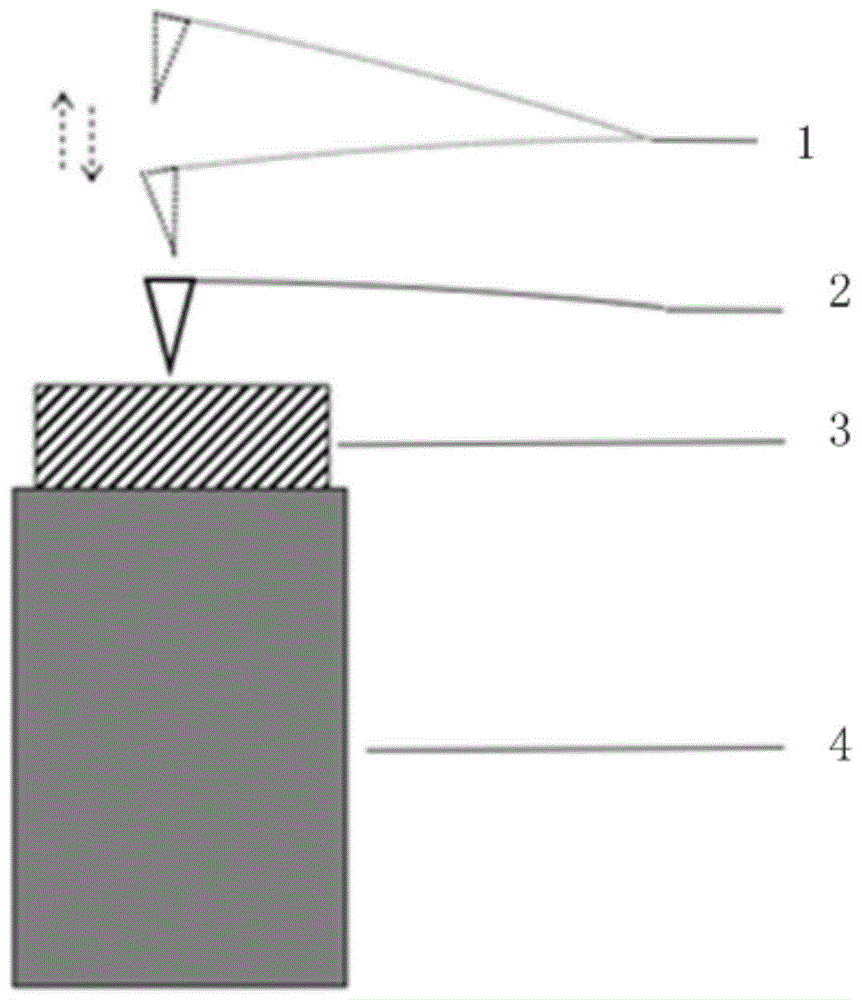
图2为本发明具体实施方式一的原子力显微镜测试性能时的硬件结构示意图,图中1表示探针在非接触模式下的位置,2表示探针在接触模式下的位置;3表示样品;4表示压电扫描管;2 is a schematic diagram of the hardware structure of the atomic force microscope in the first embodiment of the present invention when testing performance. In the figure, 1 represents the position of the probe in the non-contact mode, 2 represents the position of the probe in the contact mode; 3 represents the sample; 4 Indicates piezoelectric scanning tube;
图3为实施例1中执行非接触模式-接触模式-非接触模式切换的实时信号。其中,信号1为悬臂梁在分时激发控制系统驱动下实时的位置信号,信号2则为探针与样品之间接触导电的电流信号;FIG. 3 is a real-time signal for switching between non-contact mode-contact mode-non-contact mode in
图4为实施例2中探针与样品之间的应力应变关系图;Fig. 4 is the stress-strain relationship figure between probe and sample in
图5为实施例3原子力显微镜扫描HOPG样品的形貌图;Fig. 5 is the topography figure of
图6为实施例3中原子力显微镜扫描HOPG样品的电流图。FIG. 6 is the current diagram of the HOPG sample scanned by the atomic force microscope in Example 3.
具体实施方式detailed description
下面将结合本发明实施例中的附图,对本发明实施例中的技术方案进行清楚、完整地描述,显然,所描述的实施例仅仅是本发明一部分实施例,而不是全部的实施例。基于本发明中的实施例,本领域普通技术人员在没有作出创造性劳动的前提下所获得的所有其他实施例,都属于本发明保护的范围。The following will clearly and completely describe the technical solutions in the embodiments of the present invention with reference to the accompanying drawings in the embodiments of the present invention. Obviously, the described embodiments are only some, not all, embodiments of the present invention. Based on the embodiments of the present invention, all other embodiments obtained by persons of ordinary skill in the art without creative efforts fall within the protection scope of the present invention.
需要说明的是,在不冲突的情况下,本发明中的实施例及实施例中的特征可以相互组合。It should be noted that, in the case of no conflict, the embodiments of the present invention and the features in the embodiments can be combined with each other.
下面结合附图和具体实施例对本发明作进一步说明,但不作为本发明的限定。The present invention will be further described below in conjunction with the accompanying drawings and specific embodiments, but not as a limitation of the present invention.
本申请的非接触模式与接触模式协同工作的原子力显微镜控制方法,原子力显微镜的悬臂梁带动探针在样品上方,包括:The method for controlling the atomic force microscope in which the non-contact mode and the contact mode work together in the present application, the cantilever beam of the atomic force microscope drives the probe above the sample, including:
步骤1、原子力显微镜的悬臂梁带动探针在样品上方设定距离处,激发传感器激发悬臂梁带动探针谐振,测试长程性能;
步骤2、激发传感器停止激发,驱动样品向上运动或探针向下运动进而使样品表面紧贴上方的探针,激励传感器产生激励信号作用于样品和/或探针,测试样品的物理化学特性;
步骤3、激励传感器停止产生激励信号,同时样品或探针回到原位,驱动样品或探针移动使原子力显微镜的悬臂梁带动探针移动至下一个测试位置点,转入步骤1。
本申请中,在测试同一测试位置点时,利用分时激发控制方法,先进行非接触模式测试,然后接触模式测试,然后移动至下一测试位置点执行非接触模式测试,在同一测试位置点上调整探针与样品之间的垂直距离依次实现远程与近程性能的原位测量,使原子力显微镜能够在以非接触模式扫描的同时使用接触模式测量样品的物理化学特性。由于本实施方式在确定的一测试位置点上进行非接触模式与接触模式参数的采集与性能表征,因此可以确保能够真实表征样品本身在同一测试位置点的力、热、电、光、磁等性能,本实施方式能够实现非接触模式与接触模式两种扫描技术的组合应用,从而解决非接触模式与接触模式不兼容的问题。In this application, when testing the same test position point, the time-sharing excitation control method is used to first perform the non-contact mode test, then the contact mode test, and then move to the next test position point to perform the non-contact mode test. Adjusting the vertical distance between the probe and the sample sequentially realizes the in-situ measurement of long-range and short-range properties, enabling the AFM to measure the physicochemical properties of the sample using the contact mode while scanning in the non-contact mode. Since this embodiment collects and characterizes the parameters of non-contact mode and contact mode at a certain test position point, it can ensure that the force, heat, electricity, light, magnetism, etc. of the sample itself at the same test position point can be truly characterized. Performance, this implementation mode can realize the combined application of the two scanning technologies of the non-contact mode and the contact mode, thereby solving the problem of incompatibility between the non-contact mode and the contact mode.
本申请中,还可以在测试同一测试位置点时,利用分时激发控制方法,先执行接触模式测试,然后非接触模式测试,然后移动至下一测试位置点执行接触模式测试,在同一测试位置点上调整探针与样品之间的垂直距离依次实现进程与远程性能的原位测量,使原子力显微镜能够在以接触模式扫描的同时使用非接触模式测量样品的物理化学特性。In this application, it is also possible to use the time-sharing excitation control method when testing the same test position point to first perform the contact mode test, then the non-contact mode test, and then move to the next test position point to perform the contact mode test. On-point adjustment of the vertical distance between the probe and the sample sequentially enables in situ measurement of process and remote performance, enabling the AFM to measure the physicochemical properties of the sample using a non-contact mode while scanning in a contact mode.
本申请中操作模式的切换包括从非接触模式切换至接触模式、从接触模式切换至非接触模式,也包括从非接触模式切换至另一种非接触模式或从接触模式切换至另一种接触模式。非接触模式与接触模式两种扫描技术的组合应用是任意数量的非接触模式与任意数量的接触模式的任意排列组合。例如,非接触模式-接触模式-接触模式-非接触模式-非接触模式,或接触模式-接触模式-非接触模式-非接触模式-接触模式,等等。将具体功能赋予到原子力显微镜运行模式以后,举例说明具体的切换方案:成像模式(非接触模式)-导电力模式(接触模式)-静电力模式(非接触模式)-成像模式(非接触模式)。The switching of the operation mode in this application includes switching from non-contact mode to contact mode, switching from contact mode to non-contact mode, and also including switching from non-contact mode to another non-contact mode or switching from contact mode to another contact mode. model. The combined application of the two scanning technologies of the non-contact mode and the contact mode is any permutation and combination of any number of non-contact modes and any number of contact modes. For example, non-contact mode-contact mode-contact mode-non-contact mode-contact mode, or contact mode-contact mode-non-contact mode-non-contact mode-contact mode, and so on. After assigning specific functions to the operating mode of the atomic force microscope, give an example of the specific switching scheme: imaging mode (non-contact mode)-conductive force mode (contact mode)-electrostatic force mode (non-contact mode)-imaging mode (non-contact mode) .
本申请中物理化学特性包括样品的形貌、力学性能、热学性能、电学性能、光学性能、磁学性能、压电性能、和电化学性能。The physical and chemical properties in this application include the morphology, mechanical properties, thermal properties, electrical properties, optical properties, magnetic properties, piezoelectric properties, and electrochemical properties of the sample.
本申请中激励信号包括电学信号、磁学信号、热学信号、光学信号和力学信号。In this application, excitation signals include electrical signals, magnetic signals, thermal signals, optical signals and mechanical signals.
本申请中测试长程性能包括:对样品形貌成像、磁场力成像和静电力成像。The test of long-range performance in this application includes: imaging of sample morphology, magnetic field force imaging and electrostatic force imaging.
具体实施方式一:Specific implementation mode one:
本实施方式的硬件结构如图2所示,原子力显微镜的悬臂梁带动探针在样品3上方,样品3放在压电扫描管4上;本实施方式的硬件结构还包括激发悬臂梁带动探针谐振的激发传感器、驱动压电扫描管向上移动的位置传感器、接触模式下的激励传感器、非接触模式下的激励传感器、驱动压电扫描管水平面移动的传感器;The hardware structure of this embodiment is shown in Figure 2. The cantilever beam of the atomic force microscope drives the probe above the
具体控制过程包括:首先将所要设定的参数通过上位机传输至分时激发控制系统中,分时激发控制系统经过相应的信号生成、数模转换加载到相应传感器中。同时,硬件结构在工作中又将反馈信号通过模数转换模块传输回分时激发控制系统,而后在锁相环与负反馈等控制方法的作用下实现非接触模式与接触模式的分时协同激发技术。The specific control process includes: first, the parameters to be set are transmitted to the time-sharing excitation control system through the host computer, and the time-sharing excitation control system is loaded into the corresponding sensor through corresponding signal generation and digital-to-analog conversion. At the same time, the hardware structure transmits the feedback signal back to the time-sharing excitation control system through the analog-to-digital conversion module during work, and then realizes the time-sharing cooperative excitation technology of non-contact mode and contact mode under the action of control methods such as phase-locked loop and negative feedback. .
工作模式设定为非接触模式-接触模式-非接触模式时,分时激发控制系统通过各传感器发出的激发信号经过数模转换后作用于硬件结构时,以图2为例,当原子力显微镜处于非接触模式状态时,悬臂梁带动探针在位置1与样品3保持一定距离,激发传感器激发悬臂梁谐振,协同负反馈回路使探针与样品保持非接触状态,反馈参数信号可以根据具体要表征的物理化学特性分别设为频率、振幅、相位、电流等各种物理参数,调幅模式原子力显微镜实现对样品表面的成像,用非接触模式表征样品的长程性能,例如:样品形貌成像、磁场力成像和静电力成像;当完成上述非接触模式的操作步骤后,原子力显微镜切换至接触模式时,压电扫描管4受到位置信号传感器的驱动信号产生位移使样品向上移动,使悬臂梁带动探针处于位置2与样品3发生接触,从而使激励传感器可以对样品3进行相应的接触模式表征,此时以振幅为设定参数的负反馈回路处于关闭状态;When the working mode is set to non-contact mode-contact mode-non-contact mode, when the excitation signal sent by the time-sharing excitation control system through each sensor acts on the hardware structure after digital-to-analog conversion, take Figure 2 as an example, when the atomic force microscope is in In the non-contact mode state, the cantilever beam drives the probe to keep a certain distance from the sample at
最后当执行完接触模式中的测试任务后,原子力显微镜切换至非接触模式时,压电扫描管4会产生反向位移,带样品3向下运动,回到原位,使悬臂梁恢复位置1远离样品3从而保持非接触模式运行,此时负反馈回路将重新开启来维持探针与样品之间的动态非接触状态。Finally, after performing the test task in the contact mode, when the atomic force microscope switches to the non-contact mode, the
在上述工作模式下,假设附加确定的性能表征为导电性能。当时钟信号到达分时激发控制系统设定的切换时刻时,用于驱动悬臂梁在非接触模式下谐振的激发信号立刻关闭,此时系统驱动压电扫描管向前推进使得探针与样品接触,故可以看到明显的电流信号。当电流信号测试完毕后,原子力显微镜切换至非接触模式,探针离开样品表面使得电流消失,激发传感器激发信号恢复激励悬臂梁保持谐振状态。在两次模式切换处,激发信号与电流信号的变化可以明确的对应。In the mode of operation described above, it is assumed that an additional determined property is characterized as a conductive property. When the clock signal reaches the switching time set by the time-sharing excitation control system, the excitation signal used to drive the cantilever beam to resonate in the non-contact mode is immediately turned off. At this time, the system drives the piezoelectric scanning tube forward to make the probe contact with the sample. A clear current signal can be seen. After the current signal is tested, the atomic force microscope switches to the non-contact mode, the probe leaves the sample surface so that the current disappears, and the excitation signal of the excitation sensor resumes to excite the cantilever to maintain the resonance state. At two mode switching points, the changes of the excitation signal and the current signal can be clearly corresponded.
分时激发控制系统的信号时序示意图如图1所示,原子力显微镜在t0时刻前以非接触模式运行,激发传感器激发信号在t0时刻关闭,同时位置传感器发出驱动信号至压电扫描管4带动样品向上运动,使探针与样品间为接触状态,并且采用激励传感器施加额外激励信号至探针和/或样品开始进行特定参数的检测,完成接触模式的相关检测指令后,在t1时刻重新开启激发传感器激发信号,同时调整位置传感器的驱动信号至压电扫描管4,压电扫描管4带动样品向下运动,使样品表面回到原位,并关闭接触模式下的激励传感器激励信号。即原子力显微镜在t0时刻完成非接触模式到接触模式的切换,在t0至t1时段内维持接触状态,而后在t1时刻恢复至非接触模式。The signal timing diagram of the time-sharing excitation control system is shown in Figure 1. The atomic force microscope operates in a non-contact mode before time t 0 , and the excitation signal of the excitation sensor is turned off at time t 0. At the same time, the position sensor sends a driving signal to the
具体实施方式二:本实施方式硬件结构与图2的区别是,样品固定,原子力显微镜的悬臂梁带动探针在样品3上方,压电扫描管与悬臂梁固定,通过对压电扫描管的驱动,使悬臂梁带动探针在样品3上方进行垂直、水平面运动。硬件结构中的传感器包括激发悬臂梁带动探针谐振的激发传感器、驱动压电扫描管向下移动的位置传感器、接触模式下的激励传感器、非接触模式下的激励传感器、驱动压电扫描管水平面移动的传感器;Specific embodiment two: The difference between the hardware structure of this embodiment and that shown in Figure 2 is that the sample is fixed, the cantilever beam of the atomic force microscope drives the probe above the
具体过程包括:首先将所要设定的参数通过上位机传输至分时激发控制系统中,分时激发控制系统经过相应的信号生成、数模转换加载到相应传感器中。同时,硬件结构在工作中又将反馈信号通过模数转换模块传输回分时激发控制系统,而后在锁相环与负反馈等控制方法的作用下实现非接触模式与接触模式的分时协同激发技术。The specific process includes: first, the parameters to be set are transmitted to the time-sharing excitation control system through the host computer, and the time-sharing excitation control system is loaded into the corresponding sensor through corresponding signal generation and digital-to-analog conversion. At the same time, the hardware structure transmits the feedback signal back to the time-sharing excitation control system through the analog-to-digital conversion module during work, and then realizes the time-sharing cooperative excitation technology of non-contact mode and contact mode under the action of control methods such as phase-locked loop and negative feedback. .
工作模式设定为非接触模式-接触模式-非接触模式时,分时激发控制系统通过各传感器发出的激发信号经过数模转换后作用于硬件结构,当原子力显微镜处于非接触模式状态时,悬臂梁带动探针与样品保持一定距离,激发传感器激发悬臂梁谐振,协同负反馈回路使探针与样品保持非接触状态,反馈参数信号可以根据具体要表征的物理化学特性分别设为频率、振幅、相位、电流等各种物理参数,调幅模式原子力显微镜实现对样品表面的成像,用非接触模式表征样品的长程性能,例如:样品形貌成像、磁场力成像和静电力成像;当完成上述非接触模式的操作步骤后,原子力显微镜切换至接触模式时,压电扫描管受到位置信号传感器的驱动信号产生位移使悬臂梁带动探针向下移动,使探针与样品发生接触,从而使激励传感器可以对样品进行相应的接触模式表征,此时以振幅为设定参数的负反馈回路处于关闭状态;When the working mode is set to non-contact mode-contact mode-non-contact mode, the excitation signal sent by the time-sharing excitation control system through each sensor acts on the hardware structure after digital-to-analog conversion. When the atomic force microscope is in the state of non-contact mode, the cantilever The beam drives the probe to keep a certain distance from the sample, the sensor is excited to excite the cantilever beam to resonate, and the negative feedback loop is used to keep the probe and the sample in a non-contact state. The feedback parameter signal can be set to frequency, amplitude, Various physical parameters such as phase and current, the amplitude modulation mode atomic force microscope realizes the imaging of the sample surface, and uses the non-contact mode to characterize the long-range performance of the sample, such as: sample morphology imaging, magnetic field force imaging and electrostatic force imaging; when the above non-contact After the operation steps of the AFM mode, when the atomic force microscope is switched to the contact mode, the piezoelectric scanning tube is displaced by the driving signal of the position signal sensor, so that the cantilever beam drives the probe to move downward, so that the probe is in contact with the sample, so that the excitation sensor can Perform corresponding contact mode characterization on the sample, at this time, the negative feedback loop with the amplitude as the setting parameter is closed;
最后当执行完接触模式中的测试任务后,原子力显微镜切换至非接触模式时,压电扫描管4会产生反向位移,使悬臂梁恢复位置1远离样品3回到原位,从而保持非接触模式运行,此时负反馈回路将重新开启来维持探针与样品之间的动态非接触状态。Finally, when the atomic force microscope is switched to the non-contact mode after performing the test task in the contact mode, the
分时激发控制系统的信号时序与图1相同,原子力显微镜在t0时刻前以非接触模式运行,激发传感器激发信号在t0时刻关闭,同时位置传感器发出驱动信号至压电扫描管4使探针向下运动,与样品间为接触状态,并且采用激励传感器施加额外激励信号至探针和/或样品开始进行特定参数的检测,完成接触模式的相关检测指令后,在t1时刻重新开启激发传感器激发信号,同时调整位置传感器的驱动信号使探针离开样品表面回到原位,并关闭接触模式下的激励传感器激励信号。即原子力显微镜在t0时刻完成非接触模式到接触模式的切换,在t0至t1时段内维持接触状态,而后在t1时刻恢复至非接触模式。下面给出具体实施例:The signal sequence of the time-sharing excitation control system is the same as that in Figure 1. The atomic force microscope operates in non-contact mode before time t0 , and the excitation signal of the excitation sensor is turned off at time t0 . At the same time, the position sensor sends a driving signal to the
实施例1:Example 1:
原子力显微镜于HOPG样品上一测试位置执行非接触模式-接触模式-非接触模式切换的设计方案。在非接触模式下表征样品的形貌,在接触模式下表征样品的导电性。The atomic force microscope implements a design scheme of non-contact mode-contact mode-non-contact mode switching at a test position on the HOPG sample. Characterize the morphology of the sample in non-contact mode and characterize the conductivity of the sample in contact mode.
如图3所示,信号1为悬臂梁在分时激发控制系统控制位置传感器发出驱动信号下实时的位置信号,信号2则为探针与样品之间接触导电的电流信号。As shown in Figure 3,
信号1的前端对应悬臂梁在非接触模式下维持谐振状态的振动信号,在t=0时刻时,压电扫描管带动悬臂梁下压样品表面,此时信号1振幅大幅度减小,即在接触模式下探针主动激发的谐振停止。此外,信号1的水平位置向上平移电压增大,反应出压电扫描管的Z轴位置变化。在t=0时刻,探针与样品之间产生了明显的接触电流,信号强度为40毫伏。The front end of
采集探针与样品间的接触电流约3毫秒后,系统执行接触模式至非接触模式的切换命令。此时压电扫描管Z轴电压下降的初始位置使探针远离HOPG样品表面,激发传感器的激发信号重新开始维持悬臂梁谐振状态。同时,接触电流信号消失。After collecting the contact current between the probe and the sample for about 3 milliseconds, the system executes the switching command from the contact mode to the non-contact mode. At this time, the initial position of the Z-axis voltage drop of the piezoelectric scanning tube keeps the probe away from the surface of the HOPG sample, and the excitation signal of the excitation sensor restarts to maintain the resonance state of the cantilever beam. At the same time, the contact current signal disappears.
至此,在一测试位置处采用非接触模式-接触模式-非接触模式切换测量接触电流的命令执行完毕,耗时约4毫秒。So far, the command to measure the contact current by switching between the non-contact mode-contact mode-non-contact mode at a test location is completed, and it takes about 4 milliseconds.
实施例2:Example 2:
原子力显微镜于HOPG样品上一测试位置执行非接触模式-接触模式-非接触模式切换的设计方案。在非接触模式下表征样品的形貌,在接触模式下表征样品的应力应变性能。The atomic force microscope implements a design scheme of non-contact mode-contact mode-non-contact mode switching at a test position on the HOPG sample. Characterize the morphology of the sample in the non-contact mode, and characterize the stress-strain performance of the sample in the contact mode.
非接触模式-接触模式-非接触模式的切换步骤如上述实施例1基本相同,区别在于在切换至接触模式时,开启的性能表征功能为应力应变测试。The switching steps of non-contact mode-contact mode-non-contact mode are basically the same as the above-mentioned
如图4所示,正方形数据点组成的曲线为探针与样品由非接触状态切换至接触状态的接触应力曲线,圆形数据点组成的曲线为探针与样品由接触状态切换至非接触状态的脱附应力曲线。根据国际惯例,在图中将接触应力曲线在零点处做了关于Y轴的对称处理,便于同时在图中观察和比较两条应力应变曲线。As shown in Figure 4, the curve composed of square data points is the contact stress curve when the probe and the sample are switched from the non-contact state to the contact state, and the curve composed of circular data points is the switch from the contact state to the non-contact state between the probe and the sample. desorption stress curve. According to international practice, the contact stress curve is symmetrically processed about the Y-axis at the zero point in the figure, which is convenient for observing and comparing two stress-strain curves in the figure at the same time.
系统切换至接触模式后,压电扫描管推动样品与探针不断接近。由图4中接触应力曲线可知,当样品与探针的距离移动至3纳米以内时两者之间会产生最大约8牛顿的吸引力,当样品和探针的距离小于2.5纳米时排斥力开始明显增大,在间距为2纳米时探针与样品间的排斥力和吸引力达到平衡状态。此后,随着探针不断接近样品,两者间最大可产生约50牛顿的排斥力。After the system switches to the contact mode, the piezoelectric scanning tube pushes the sample and the probe closer together. From the contact stress curve in Figure 4, it can be seen that when the distance between the sample and the probe moves within 3 nanometers, there will be a maximum attraction force of about 8 Newtons between the two, and the repulsive force will start when the distance between the sample and the probe is less than 2.5 nanometers. The repulsive force and attractive force between the probe and the sample reach a balance state when the spacing is 2 nm. Thereafter, as the probe approaches the sample, a maximum repulsive force of about 50 Newtons can be generated between the two.
当系统向非接触模式切换时,压电扫描管带动样品远离探针。此时,探针与样品间的排斥力逐渐减小,观察脱附应力曲线可知,由于探针按压进了样品,所以在脱附时会产生18牛顿的最大吸引力,明显大于接触时的最大吸引力。此外,脱附阶段样品与探针间的引力斥力平衡点和引力起始点,分别向后移动了约2纳米和7纳米。When the system switches to non-contact mode, the piezo scan tube moves the sample away from the probe. At this time, the repulsive force between the probe and the sample gradually decreases. Observing the desorption stress curve shows that since the probe is pressed into the sample, a maximum attractive force of 18 Newtons will be generated during desorption, which is significantly greater than the maximum force during contact. attraction. In addition, the equilibrium point of the gravitational-repulsive force and the starting point of the gravitational force between the sample and the probe in the desorption stage moved backward by about 2 nanometers and 7 nanometers, respectively.
实施例3:Example 3:
原子力显微镜于HOPG样品上一块1微米乘以1微米的区域执行非接触模式-接触模式-非接触模式切换的设计方案。在非接触模式下表征样品的形貌,在接触模式下表征样品的导电性。The atomic force microscope implements a non-contact mode-contact mode-non-contact mode switching design scheme on a 1 micron by 1 micron area on the HOPG sample. Characterize the morphology of the sample in non-contact mode and characterize the conductivity of the sample in contact mode.
本实施例是在扫描区域内的X轴512乘Y轴512个点上分别执行实施例1中的单测试位置点操作后的集合,在每一测试位置点上的控制命令与所述实施例1中的命令相同。除此之外,需要额外设定扫描探针显微镜工作的基本参数,即扫描位置、扫描点数、扫描速度、扫描斜率等等。This embodiment is a set after performing the single test position point operation in
图5为原子力显微镜扫描HOPG样品某一特定区域的形貌图,图6为原子力显微镜扫描该HOPG样品同一区域的接触电流图。对比两幅图像可以看出,样品的形貌图像与接触电流图像有准确的对应关系,形貌的高低起伏处对应样品与探针接触电流的大小也有着符合形貌规律的大小变化。Fig. 5 is a topography diagram of a specific region of the HOPG sample scanned by an atomic force microscope, and Fig. 6 is a contact current diagram of the same region of the HOPG sample scanned by an atomic force microscope. Comparing the two images, it can be seen that there is an accurate correspondence between the topography image of the sample and the contact current image, and the high and low fluctuations of the topography correspond to the magnitude of the contact current between the sample and the probe, and there is also a change in size that conforms to the topography rule.
由此可以证明本申请的非接触模式与接触模式协同工作技术确实可以实现材料的多场耦合原位表征,解决了传统二次扫描技术由于机械设备本征缺陷导致的形貌图与电流图无法准确对应的问题。It can be proved that the non-contact mode and contact mode cooperative working technology of the present application can indeed realize the multi-field coupling in-situ characterization of materials, and solve the inability of the topography map and current map caused by the intrinsic defects of mechanical equipment in the traditional secondary scanning technology. exact problem.
虽然在本文中参照了特定的实施方式来描述本发明,但是应该理解的是,这些实施例仅仅是本发明的原理和应用的示例。因此应该理解的是,可以对示例性的实施例进行许多修改,并且可以设计出其他的布置,只要不偏离所附权利要求所限定的本发明的精神和范围。应该理解的是,可以通过不同于原始权利要求所描述的方式来结合不同的从属权利要求和本文中所述的特征。还可以理解的是,结合单独实施例所描述的特征可以使用在其他所述实施例中。Although the invention is described herein with reference to specific embodiments, it should be understood that these embodiments are merely illustrative of the principles and applications of the invention. It is therefore to be understood that numerous modifications may be made to the exemplary embodiments and that other arrangements may be devised without departing from the spirit and scope of the invention as defined by the appended claims. It shall be understood that different dependent claims and features described herein may be combined in a different way than that described in the original claims. It will also be appreciated that features described in connection with individual embodiments can be used in other described embodiments.
Claims (10)
Priority Applications (1)
| Application Number | Priority Date | Filing Date | Title |
|---|---|---|---|
| CN202211165715.3A CN115480077B (en) | 2022-09-23 | 2022-09-23 | Atomic force microscope control method with cooperative operation of non-contact mode and contact mode |
Applications Claiming Priority (1)
| Application Number | Priority Date | Filing Date | Title |
|---|---|---|---|
| CN202211165715.3A CN115480077B (en) | 2022-09-23 | 2022-09-23 | Atomic force microscope control method with cooperative operation of non-contact mode and contact mode |
Publications (2)
| Publication Number | Publication Date |
|---|---|
| CN115480077A true CN115480077A (en) | 2022-12-16 |
| CN115480077B CN115480077B (en) | 2024-08-23 |
Family
ID=84393489
Family Applications (1)
| Application Number | Title | Priority Date | Filing Date |
|---|---|---|---|
| CN202211165715.3A Active CN115480077B (en) | 2022-09-23 | 2022-09-23 | Atomic force microscope control method with cooperative operation of non-contact mode and contact mode |
Country Status (1)
| Country | Link |
|---|---|
| CN (1) | CN115480077B (en) |
Citations (13)
| Publication number | Priority date | Publication date | Assignee | Title |
|---|---|---|---|---|
| JPH10282126A (en) * | 1997-04-04 | 1998-10-23 | Nikon Corp | Scanning probe microscope and its sample observation method |
| US5918274A (en) * | 1997-06-02 | 1999-06-29 | International Business Machines Corporation | Detecting fields with a single-pass, dual-amplitude-mode scanning force microscope |
| JPH11352135A (en) * | 1998-06-04 | 1999-12-24 | Seiko Instruments Inc | Interatomic force microscope |
| JP2002022637A (en) * | 2000-07-04 | 2002-01-23 | Shimadzu Corp | Scanning probe microscope |
| US20050140387A1 (en) * | 2002-08-26 | 2005-06-30 | Takuya Matsumoto | Probe device and method of controlling the same |
| JP2008281550A (en) * | 2007-04-10 | 2008-11-20 | Hitachi Ltd | Scanning probe microscope |
| JP2012167928A (en) * | 2011-02-09 | 2012-09-06 | Sii Nanotechnology Inc | Surface property measurement device and scanning method thereof |
| CN108802431A (en) * | 2017-05-04 | 2018-11-13 | 中国科学院宁波材料技术与工程研究所 | A kind of detection method of the scanning probe microscopy with magnetic-electric signal detecting function |
| CN110095637A (en) * | 2019-05-08 | 2019-08-06 | 国家纳米科学中心 | The test method of atomic force microscope and sample surfaces property |
| US20190353681A1 (en) * | 2016-11-10 | 2019-11-21 | Nederlandse Organisatie Voor Toegepast-Natuurwetenschappelijk Onderzoek Tno | Method of modifying a surface of a sample, and a scanning probe microscopy system |
| CN111721750A (en) * | 2020-06-23 | 2020-09-29 | 深圳大学 | Method and device for enhancing TERS signal in non-contact mode of atomic force microscope |
| US20210003608A1 (en) * | 2018-03-21 | 2021-01-07 | Nederlandse Organisatie Voor Toegepast-Natuurwetenschappelijk Onderzoek Tno | Method and system for at least subsurface characterization of a sample |
| CN112964910A (en) * | 2020-09-16 | 2021-06-15 | 中国科学院沈阳自动化研究所 | Atomic force microscope integrated double-probe rapid in-situ switching measurement method and device |
-
2022
- 2022-09-23 CN CN202211165715.3A patent/CN115480077B/en active Active
Patent Citations (13)
| Publication number | Priority date | Publication date | Assignee | Title |
|---|---|---|---|---|
| JPH10282126A (en) * | 1997-04-04 | 1998-10-23 | Nikon Corp | Scanning probe microscope and its sample observation method |
| US5918274A (en) * | 1997-06-02 | 1999-06-29 | International Business Machines Corporation | Detecting fields with a single-pass, dual-amplitude-mode scanning force microscope |
| JPH11352135A (en) * | 1998-06-04 | 1999-12-24 | Seiko Instruments Inc | Interatomic force microscope |
| JP2002022637A (en) * | 2000-07-04 | 2002-01-23 | Shimadzu Corp | Scanning probe microscope |
| US20050140387A1 (en) * | 2002-08-26 | 2005-06-30 | Takuya Matsumoto | Probe device and method of controlling the same |
| JP2008281550A (en) * | 2007-04-10 | 2008-11-20 | Hitachi Ltd | Scanning probe microscope |
| JP2012167928A (en) * | 2011-02-09 | 2012-09-06 | Sii Nanotechnology Inc | Surface property measurement device and scanning method thereof |
| US20190353681A1 (en) * | 2016-11-10 | 2019-11-21 | Nederlandse Organisatie Voor Toegepast-Natuurwetenschappelijk Onderzoek Tno | Method of modifying a surface of a sample, and a scanning probe microscopy system |
| CN108802431A (en) * | 2017-05-04 | 2018-11-13 | 中国科学院宁波材料技术与工程研究所 | A kind of detection method of the scanning probe microscopy with magnetic-electric signal detecting function |
| US20210003608A1 (en) * | 2018-03-21 | 2021-01-07 | Nederlandse Organisatie Voor Toegepast-Natuurwetenschappelijk Onderzoek Tno | Method and system for at least subsurface characterization of a sample |
| CN110095637A (en) * | 2019-05-08 | 2019-08-06 | 国家纳米科学中心 | The test method of atomic force microscope and sample surfaces property |
| CN111721750A (en) * | 2020-06-23 | 2020-09-29 | 深圳大学 | Method and device for enhancing TERS signal in non-contact mode of atomic force microscope |
| CN112964910A (en) * | 2020-09-16 | 2021-06-15 | 中国科学院沈阳自动化研究所 | Atomic force microscope integrated double-probe rapid in-situ switching measurement method and device |
Also Published As
| Publication number | Publication date |
|---|---|
| CN115480077B (en) | 2024-08-23 |
Similar Documents
| Publication | Publication Date | Title |
|---|---|---|
| CN102439462B (en) | Method and apparatus for operating a scanning probe microscope | |
| KR20060033798A (en) | Probe for atomic force microscopy | |
| JP2005531781A (en) | Scanning probe microscope | |
| JP2004523748A5 (en) | ||
| CN106841687A (en) | The method that multi-parameter synchro measure is carried out using Kelvin probe force microscopy | |
| CN111398638B (en) | Kelvin probe force microscope system and sample side wall scanning method | |
| CN110095637A (en) | The test method of atomic force microscope and sample surfaces property | |
| CN108802431A (en) | A kind of detection method of the scanning probe microscopy with magnetic-electric signal detecting function | |
| CN101458203B (en) | Double probe same-point measurement scanning probe microscope | |
| US20080295585A1 (en) | Tweezer-Equipped Scanning Probe Microscope and Transfer Method | |
| CN1836290A (en) | Probe for an atomic force microscope | |
| JP2008256579A (en) | Scanning probe microscope and scanning method thereof | |
| US20150204902A1 (en) | Method and apparatus of tuning a scanning probe microscope | |
| CN103645347B (en) | The single-point tracking measurement method of micro-nano-scale Dynamic Coupling vibration | |
| CN103901234A (en) | In-situ integration representation device of multiferroic material nanoscale domain structure | |
| JPWO2012033131A1 (en) | Surface processing equipment using a scanning probe microscope | |
| CN115480077A (en) | Atomic force microscope control method with cooperative work of non-contact mode and contact mode | |
| KR101630392B1 (en) | Topography signal and option signal acquisition apparatus, method and atomic force microscope having the same | |
| JP5079109B2 (en) | Scanning probe microscope | |
| JPWO2014006734A1 (en) | Force probe microscope and height distribution measuring method | |
| JP4474556B2 (en) | Scanning probe microscope | |
| JP2006153574A (en) | Atomic force microscope | |
| JP2011252849A (en) | Excitation method for cantilever in atomic force microscope and atomic force microscope | |
| JP2009019943A (en) | Scanning probe microscope | |
| CN101226125B (en) | Frictionless inertial step scanner, control method, same-spot scanning dual-probe microscope |
Legal Events
| Date | Code | Title | Description |
|---|---|---|---|
| PB01 | Publication | ||
| PB01 | Publication | ||
| SE01 | Entry into force of request for substantive examination | ||
| SE01 | Entry into force of request for substantive examination | ||
| GR01 | Patent grant | ||
| GR01 | Patent grant |