CN115503473A - Function display and associated operating elements for optionally displaying at least one symbol representing a switching function and/or a plurality of switching states - Google Patents
Function display and associated operating elements for optionally displaying at least one symbol representing a switching function and/or a plurality of switching states Download PDFInfo
- Publication number
- CN115503473A CN115503473A CN202210550286.5A CN202210550286A CN115503473A CN 115503473 A CN115503473 A CN 115503473A CN 202210550286 A CN202210550286 A CN 202210550286A CN 115503473 A CN115503473 A CN 115503473A
- Authority
- CN
- China
- Prior art keywords
- light
- display
- light guide
- observer
- functional
- Prior art date
- Legal status (The legal status is an assumption and is not a legal conclusion. Google has not performed a legal analysis and makes no representation as to the accuracy of the status listed.)
- Granted
Links
Images


Classifications
-
- G—PHYSICS
- G09—EDUCATION; CRYPTOGRAPHY; DISPLAY; ADVERTISING; SEALS
- G09F—DISPLAYING; ADVERTISING; SIGNS; LABELS OR NAME-PLATES; SEALS
- G09F21/00—Mobile visual advertising
- G09F21/04—Mobile visual advertising by land vehicles
-
- B—PERFORMING OPERATIONS; TRANSPORTING
- B60—VEHICLES IN GENERAL
- B60K—ARRANGEMENT OR MOUNTING OF PROPULSION UNITS OR OF TRANSMISSIONS IN VEHICLES; ARRANGEMENT OR MOUNTING OF PLURAL DIVERSE PRIME-MOVERS IN VEHICLES; AUXILIARY DRIVES FOR VEHICLES; INSTRUMENTATION OR DASHBOARDS FOR VEHICLES; ARRANGEMENTS IN CONNECTION WITH COOLING, AIR INTAKE, GAS EXHAUST OR FUEL SUPPLY OF PROPULSION UNITS IN VEHICLES
- B60K35/00—Instruments specially adapted for vehicles; Arrangement of instruments in or on vehicles
- B60K35/20—Output arrangements, i.e. from vehicle to user, associated with vehicle functions or specially adapted therefor
- B60K35/28—Output arrangements, i.e. from vehicle to user, associated with vehicle functions or specially adapted therefor characterised by the type of the output information, e.g. video entertainment or vehicle dynamics information; characterised by the purpose of the output information, e.g. for attracting the attention of the driver
-
- B—PERFORMING OPERATIONS; TRANSPORTING
- B60—VEHICLES IN GENERAL
- B60K—ARRANGEMENT OR MOUNTING OF PROPULSION UNITS OR OF TRANSMISSIONS IN VEHICLES; ARRANGEMENT OR MOUNTING OF PLURAL DIVERSE PRIME-MOVERS IN VEHICLES; AUXILIARY DRIVES FOR VEHICLES; INSTRUMENTATION OR DASHBOARDS FOR VEHICLES; ARRANGEMENTS IN CONNECTION WITH COOLING, AIR INTAKE, GAS EXHAUST OR FUEL SUPPLY OF PROPULSION UNITS IN VEHICLES
- B60K35/00—Instruments specially adapted for vehicles; Arrangement of instruments in or on vehicles
- B60K35/10—Input arrangements, i.e. from user to vehicle, associated with vehicle functions or specially adapted therefor
-
- B—PERFORMING OPERATIONS; TRANSPORTING
- B60—VEHICLES IN GENERAL
- B60K—ARRANGEMENT OR MOUNTING OF PROPULSION UNITS OR OF TRANSMISSIONS IN VEHICLES; ARRANGEMENT OR MOUNTING OF PLURAL DIVERSE PRIME-MOVERS IN VEHICLES; AUXILIARY DRIVES FOR VEHICLES; INSTRUMENTATION OR DASHBOARDS FOR VEHICLES; ARRANGEMENTS IN CONNECTION WITH COOLING, AIR INTAKE, GAS EXHAUST OR FUEL SUPPLY OF PROPULSION UNITS IN VEHICLES
- B60K35/00—Instruments specially adapted for vehicles; Arrangement of instruments in or on vehicles
- B60K35/20—Output arrangements, i.e. from vehicle to user, associated with vehicle functions or specially adapted therefor
- B60K35/21—Output arrangements, i.e. from vehicle to user, associated with vehicle functions or specially adapted therefor using visual output, e.g. blinking lights or matrix displays
- B60K35/212—Output arrangements, i.e. from vehicle to user, associated with vehicle functions or specially adapted therefor using visual output, e.g. blinking lights or matrix displays displaying on manual operation elements, e.g. on a knob
-
- B—PERFORMING OPERATIONS; TRANSPORTING
- B60—VEHICLES IN GENERAL
- B60K—ARRANGEMENT OR MOUNTING OF PROPULSION UNITS OR OF TRANSMISSIONS IN VEHICLES; ARRANGEMENT OR MOUNTING OF PLURAL DIVERSE PRIME-MOVERS IN VEHICLES; AUXILIARY DRIVES FOR VEHICLES; INSTRUMENTATION OR DASHBOARDS FOR VEHICLES; ARRANGEMENTS IN CONNECTION WITH COOLING, AIR INTAKE, GAS EXHAUST OR FUEL SUPPLY OF PROPULSION UNITS IN VEHICLES
- B60K35/00—Instruments specially adapted for vehicles; Arrangement of instruments in or on vehicles
- B60K35/20—Output arrangements, i.e. from vehicle to user, associated with vehicle functions or specially adapted therefor
- B60K35/21—Output arrangements, i.e. from vehicle to user, associated with vehicle functions or specially adapted therefor using visual output, e.g. blinking lights or matrix displays
- B60K35/22—Display screens
-
- B—PERFORMING OPERATIONS; TRANSPORTING
- B60—VEHICLES IN GENERAL
- B60K—ARRANGEMENT OR MOUNTING OF PROPULSION UNITS OR OF TRANSMISSIONS IN VEHICLES; ARRANGEMENT OR MOUNTING OF PLURAL DIVERSE PRIME-MOVERS IN VEHICLES; AUXILIARY DRIVES FOR VEHICLES; INSTRUMENTATION OR DASHBOARDS FOR VEHICLES; ARRANGEMENTS IN CONNECTION WITH COOLING, AIR INTAKE, GAS EXHAUST OR FUEL SUPPLY OF PROPULSION UNITS IN VEHICLES
- B60K35/00—Instruments specially adapted for vehicles; Arrangement of instruments in or on vehicles
- B60K35/60—Instruments characterised by their location or relative disposition in or on vehicles
-
- G—PHYSICS
- G02—OPTICS
- G02B—OPTICAL ELEMENTS, SYSTEMS OR APPARATUS
- G02B6/00—Light guides; Structural details of arrangements comprising light guides and other optical elements, e.g. couplings
- G02B6/0001—Light guides; Structural details of arrangements comprising light guides and other optical elements, e.g. couplings specially adapted for lighting devices or systems
- G02B6/0011—Light guides; Structural details of arrangements comprising light guides and other optical elements, e.g. couplings specially adapted for lighting devices or systems the light guides being planar or of plate-like form
- G02B6/0013—Means for improving the coupling-in of light from the light source into the light guide
- G02B6/0015—Means for improving the coupling-in of light from the light source into the light guide provided on the surface of the light guide or in the bulk of it
- G02B6/002—Means for improving the coupling-in of light from the light source into the light guide provided on the surface of the light guide or in the bulk of it by shaping at least a portion of the light guide, e.g. with collimating, focussing or diverging surfaces
-
- G—PHYSICS
- G02—OPTICS
- G02B—OPTICAL ELEMENTS, SYSTEMS OR APPARATUS
- G02B6/00—Light guides; Structural details of arrangements comprising light guides and other optical elements, e.g. couplings
- G02B6/0001—Light guides; Structural details of arrangements comprising light guides and other optical elements, e.g. couplings specially adapted for lighting devices or systems
- G02B6/0011—Light guides; Structural details of arrangements comprising light guides and other optical elements, e.g. couplings specially adapted for lighting devices or systems the light guides being planar or of plate-like form
- G02B6/0033—Means for improving the coupling-out of light from the light guide
- G02B6/0058—Means for improving the coupling-out of light from the light guide varying in density, size, shape or depth along the light guide
- G02B6/006—Means for improving the coupling-out of light from the light guide varying in density, size, shape or depth along the light guide to produce indicia, symbols, texts or the like
-
- G—PHYSICS
- G02—OPTICS
- G02B—OPTICAL ELEMENTS, SYSTEMS OR APPARATUS
- G02B6/00—Light guides; Structural details of arrangements comprising light guides and other optical elements, e.g. couplings
- G02B6/0001—Light guides; Structural details of arrangements comprising light guides and other optical elements, e.g. couplings specially adapted for lighting devices or systems
- G02B6/0011—Light guides; Structural details of arrangements comprising light guides and other optical elements, e.g. couplings specially adapted for lighting devices or systems the light guides being planar or of plate-like form
- G02B6/0075—Arrangements of multiple light guides
- G02B6/0076—Stacked arrangements of multiple light guides of the same or different cross-sectional area
-
- G—PHYSICS
- G09—EDUCATION; CRYPTOGRAPHY; DISPLAY; ADVERTISING; SEALS
- G09F—DISPLAYING; ADVERTISING; SIGNS; LABELS OR NAME-PLATES; SEALS
- G09F13/00—Illuminated signs; Luminous advertising
- G09F13/04—Signs, boards or panels, illuminated from behind the insignia
- G09F13/0418—Constructional details
- G09F13/0458—Interchangeable panels
-
- G—PHYSICS
- G09—EDUCATION; CRYPTOGRAPHY; DISPLAY; ADVERTISING; SEALS
- G09F—DISPLAYING; ADVERTISING; SIGNS; LABELS OR NAME-PLATES; SEALS
- G09F13/00—Illuminated signs; Luminous advertising
- G09F13/18—Edge-illuminated signs
-
- B—PERFORMING OPERATIONS; TRANSPORTING
- B60—VEHICLES IN GENERAL
- B60K—ARRANGEMENT OR MOUNTING OF PROPULSION UNITS OR OF TRANSMISSIONS IN VEHICLES; ARRANGEMENT OR MOUNTING OF PLURAL DIVERSE PRIME-MOVERS IN VEHICLES; AUXILIARY DRIVES FOR VEHICLES; INSTRUMENTATION OR DASHBOARDS FOR VEHICLES; ARRANGEMENTS IN CONNECTION WITH COOLING, AIR INTAKE, GAS EXHAUST OR FUEL SUPPLY OF PROPULSION UNITS IN VEHICLES
- B60K2360/00—Indexing scheme associated with groups B60K35/00 or B60K37/00 relating to details of instruments or dashboards
- B60K2360/143—Touch sensitive instrument input devices
- B60K2360/1446—Touch switches
-
- B—PERFORMING OPERATIONS; TRANSPORTING
- B60—VEHICLES IN GENERAL
- B60K—ARRANGEMENT OR MOUNTING OF PROPULSION UNITS OR OF TRANSMISSIONS IN VEHICLES; ARRANGEMENT OR MOUNTING OF PLURAL DIVERSE PRIME-MOVERS IN VEHICLES; AUXILIARY DRIVES FOR VEHICLES; INSTRUMENTATION OR DASHBOARDS FOR VEHICLES; ARRANGEMENTS IN CONNECTION WITH COOLING, AIR INTAKE, GAS EXHAUST OR FUEL SUPPLY OF PROPULSION UNITS IN VEHICLES
- B60K2360/00—Indexing scheme associated with groups B60K35/00 or B60K37/00 relating to details of instruments or dashboards
- B60K2360/16—Type of output information
- B60K2360/161—Explanation of functions, e.g. instructions
-
- B—PERFORMING OPERATIONS; TRANSPORTING
- B60—VEHICLES IN GENERAL
- B60K—ARRANGEMENT OR MOUNTING OF PROPULSION UNITS OR OF TRANSMISSIONS IN VEHICLES; ARRANGEMENT OR MOUNTING OF PLURAL DIVERSE PRIME-MOVERS IN VEHICLES; AUXILIARY DRIVES FOR VEHICLES; INSTRUMENTATION OR DASHBOARDS FOR VEHICLES; ARRANGEMENTS IN CONNECTION WITH COOLING, AIR INTAKE, GAS EXHAUST OR FUEL SUPPLY OF PROPULSION UNITS IN VEHICLES
- B60K2360/00—Indexing scheme associated with groups B60K35/00 or B60K37/00 relating to details of instruments or dashboards
- B60K2360/16—Type of output information
- B60K2360/167—Vehicle dynamics information
-
- B—PERFORMING OPERATIONS; TRANSPORTING
- B60—VEHICLES IN GENERAL
- B60K—ARRANGEMENT OR MOUNTING OF PROPULSION UNITS OR OF TRANSMISSIONS IN VEHICLES; ARRANGEMENT OR MOUNTING OF PLURAL DIVERSE PRIME-MOVERS IN VEHICLES; AUXILIARY DRIVES FOR VEHICLES; INSTRUMENTATION OR DASHBOARDS FOR VEHICLES; ARRANGEMENTS IN CONNECTION WITH COOLING, AIR INTAKE, GAS EXHAUST OR FUEL SUPPLY OF PROPULSION UNITS IN VEHICLES
- B60K2360/00—Indexing scheme associated with groups B60K35/00 or B60K37/00 relating to details of instruments or dashboards
- B60K2360/77—Instrument locations other than the dashboard
- B60K2360/782—Instrument locations other than the dashboard on the steering wheel
-
- B—PERFORMING OPERATIONS; TRANSPORTING
- B62—LAND VEHICLES FOR TRAVELLING OTHERWISE THAN ON RAILS
- B62D—MOTOR VEHICLES; TRAILERS
- B62D1/00—Steering controls, i.e. means for initiating a change of direction of the vehicle
- B62D1/02—Steering controls, i.e. means for initiating a change of direction of the vehicle vehicle-mounted
- B62D1/04—Hand wheels
- B62D1/046—Adaptations on rotatable parts of the steering wheel for accommodation of switches
Landscapes
- Engineering & Computer Science (AREA)
- Transportation (AREA)
- Chemical & Material Sciences (AREA)
- Combustion & Propulsion (AREA)
- Mechanical Engineering (AREA)
- Physics & Mathematics (AREA)
- General Physics & Mathematics (AREA)
- Optics & Photonics (AREA)
- Theoretical Computer Science (AREA)
- Business, Economics & Management (AREA)
- Accounting & Taxation (AREA)
- Marketing (AREA)
- Illuminated Signs And Luminous Advertising (AREA)
Abstract
本发明涉及一种功能显示器,具有:光导体叠堆,形成面向观察者的显示面;光导体叠堆由在叠堆方向上重叠布置的至少两个透明或半透明的平面状光导体形成,光导体布置为被透明的或半透明的层,层由与相邻光导体相比光学上更稀薄的材料形成;每一个光导体的至少一个光源,被布置为使光经由相关的光导体的端面入射到相应的光导体中;其中每一个光导体还设置有至少一个设置在光导体中或其上微结构化的符号区域,包括多个微结构并且被形成为在光源激活的情况下借助于入射到光导体中的光的照明对于观察者是可见的;在光导体叠堆的背离观察者的侧面上布置的反射镜,以便将入射到至少一个光导体中并且随后从光导体中出射的光向观察者反射。
The invention relates to a functional display, comprising: a stack of photoconductors forming a display surface facing the viewer; the stack of photoconductors is formed by at least two transparent or translucent planar photoconductors arranged one above the other in the direction of the stack, The light guides are arranged as a transparent or translucent layer formed of an optically thinner material than adjacent light guides; at least one light source of each light guide is arranged to cause light to pass through the associated light guide The end face is incident into the corresponding light guide; wherein each light guide is also provided with at least one microstructured symbol area arranged in or on the light guide, comprising a plurality of microstructures and formed so that when the light source is activated by means of The illumination due to the light incident in the light guide is visible to the observer; the reflector arranged on the side of the light guide stack facing away from the observer, so that the light incident into at least one light guide and subsequently exit from the light guide light is reflected towards the observer.
Description
技术领域technical field
本发明涉及一种用于选择性显示至少一个代表开关功能和/或多个开关状态的符号的功 能显示器。The invention relates to a function display for selectively displaying at least one symbol representing a switching function and/or a plurality of switching states.
背景技术Background technique
这些功能显示器例如在用于多功能操作元件中是必需的,以便将与操作元件相关联的开 关功能和/或开关状态可视化。为此通常使用电子像素矩阵显示器。然而它们是相对较贵的, 由于其大多数情况下矩形的形状而限制其构型设计和摆放。此外,电子像素矩阵显示器在显 示静态显示内容时通常倾向于“烧屏”,也就是说,由于显示器的成像层的可视觉感知的损 伤,即使在显示器关闭的情况下,显示内容令人不希望地保持持续可见。此外,此类电子像 素矩阵显示器的耗电量相对较高。另外,在某些应用中,由于例如在头部碰撞的情况下的受 伤危险,禁止使用常规的电子像素矩阵显示器。作为像素矩阵显示器的替代物已知的是,光 源的入射到光导体的端面中的光借助于用作显示面的主面处的表面结构有针对性地出射,其 中仅仅局部设置设有表面结构的区域并且重现符号等。在此不利的是,符号大多数情况下是 视觉上不引人注目的并且因此可能容易被观察者忽视。这导致观察者、尤其车辆驾驶员例如 错误地估计实际的开关状态。These function displays are required, for example, for multifunctional operating elements in order to visualize the switching functions and/or switching states associated with the operating elements. Electronic pixel matrix displays are usually used for this purpose. They are however relatively expensive, limiting their configuration and placement due to their mostly rectangular shape. Furthermore, electronic pixel-matrix displays are often prone to "burn-in" when displaying static display content, that is, the display content is undesirably rendered even when the display is turned off due to visually perceivable damage to the imaging layers of the display remain continuously visible. Furthermore, such electronic pixel-matrix displays have a relatively high power consumption. Furthermore, in certain applications the use of conventional electronic pixel matrix displays is prohibited due to the risk of injury, for example in the event of a head impact. As an alternative to pixel-matrix displays, it is known that light from a light source impinging on an end face of an optical waveguide is emitted in a targeted manner by means of a surface structure on the main surface serving as display surface, wherein the surface structure is only provided locally area and reproduce symbols, etc. The disadvantage here is that the symbols are mostly visually inconspicuous and can therefore be easily overlooked by the observer. This leads to observers, especially the vehicle driver, for example, erroneously estimating the actual switch state.
发明内容Contents of the invention
在此背景下,本发明的目的是提供一种功能显示器,所述功能显示器创造了提高显示丰 富性并由此提高观察者的关注度的可能性,尤其可以通过附加的显示平面产生深度效果并且 此外还可以成本有效地制造,所述功能显示器是节能且可靠的和/或尤其在头部撞击的情况下 减少受伤风险。这个目的通过权利要求1所述的功能显示器实现。对应地有利的操作元件、 包含所述功能显示器的方向盘以及由多个功能显示器形成的组件分别是并列主权利要求的主 题。有利的设计方案分别是从属权利要求的主题。要注意的是,在权利要求书中单独详述的 特征可以以任意的技术上有意义的方式彼此组合并且展现出本发明的其他设计方案。说明书 尤其与附图结合地附加表征并且详细说明本发明。Against this background, the object of the present invention is to provide a functional display that creates the possibility of increasing the richness of the display and thus the attention of the observer, in particular the possibility of creating depth effects by means of additional display planes and Furthermore, it can be produced cost-effectively, the functional display is energy-efficient and reliable and/or reduces the risk of injury, especially in the event of a head impact. This object is achieved by a functional display as claimed in
本发明涉及一种尤其用于机动车辆的用于选择性显示至少一个代表开关功能和/或多个 开关状态的符号的功能显示器。选择性显示不仅理解为从多个预先给定的符号中可选择地显 示不同符号,这在本发明的解决方案中通过从多个光源中选择性地选出一个或多个光源并且 将其通电来实现,而且还理解为开关光源以通过被激活的背光照明在视觉上为观察者选择性 地显现符号或者通过关闭背光照明使符号对于观察者而言尽可能接近消失。The invention relates to a function display for selectively displaying at least one symbol representing a switching function and/or a plurality of switching states, in particular for a motor vehicle. Selective display is not only understood as selectively displaying different symbols from a plurality of predetermined symbols, which in the solution of the present invention is achieved by selectively selecting one or more light sources from a plurality of light sources and energizing them To be realized, but also to be understood as switching the light source to visually selectively reveal the symbol to the observer by the activated backlighting or to make the symbol disappear as close as possible to the observer by turning off the backlighting.
根据本发明的功能显示器具有光导体叠堆,所述光导体叠堆在按照预期安装所述功能显 示器的情况下形成面向观察者的显示面。所述光导体叠堆由在叠堆方向上重叠布置的至少两 个透明或半透明的平面状光导体形成,所述光导体被布置为被透明的或半透明的层、优选经 由气隙间隔开,所述层由与相邻光导体相比光学上更稀薄的材料形成。在此,所述光导体分 别具有面向观察者的主面和背离观察者的主面。在至少一个光导体处,背离观察者的主面面 向在叠堆方向上的下一个相邻的光导体。The functional display according to the invention has an optical waveguide stack which forms a display surface facing the viewer when the functional display is installed as intended. The light guide stack is formed by at least two transparent or translucent planar light guides arranged one above the other in the stack direction, which are arranged separated by a transparent or translucent layer, preferably via an air gap On, the layer is formed from an optically thinner material than the adjacent light conductor. In this case, the light guide has a main surface facing the observer and a main surface facing away from the observer. At at least one light guide, the main face facing away from the observer faces the next adjacent light guide in the stacking direction.
根据本发明的功能显示器可以任选地具有布置在所述光导体叠堆与观察者之间的外部的 透明或半透明的覆盖层,通过所述覆盖层在按照预期布置所述功能显示器的情况下由所述光 导体叠堆限定的显示面对于观察者而言是可见的。覆盖层和光导体的材料例如为塑料、优选 热塑料,如聚乙烯(PE)、聚碳酸酯(PC)、聚苯乙烯(PS)、聚氯乙烯(PVC)、聚酰胺 (PA)、丙烯腈-丁二烯-苯乙烯(ABS)或聚甲基丙烯酸甲酯(PMMA),或者玻璃材料。The functional display according to the invention can optionally have an outer transparent or translucent cover layer arranged between the light conductor stack and the observer, through which the functional display is arranged as intended The lower display surface defined by the light conductor stack is visible to a viewer. Materials for the cover layer and light guide are, for example, plastics, preferably thermoplastics, such as polyethylene (PE), polycarbonate (PC), polystyrene (PS), polyvinyl chloride (PVC), polyamide (PA), acrylonitrile - Butadiene-styrene (ABS) or polymethylmethacrylate (PMMA), or glass material.
根据本发明,每一个光导体设置有至少一个光源,所述光源被布置为使光经由相关的光 导体的端面入射到相应的光导体中。所述光导体例如具有两个彼此对置的、优选彼此平行延 伸的主面,所述主面经由端面例如在所述光导体的窄边处并且在长边处相连,所述端面与所 述光导体的主面一起形成共用的边沿。所述端面例如与所述光导体的至少一个主面或这两个 主面正交。According to the invention, each light guide is provided with at least one light source arranged to cause light to be incident into the respective light guide via an end face of the relevant light guide. The light guide has, for example, two opposite main surfaces, preferably extending parallel to one another, which are connected via end surfaces, for example at narrow sides and at long sides of the light guide, which are connected to the The main areas of the light guide together form a common edge. The end faces are, for example, orthogonal to at least one main face or to both main faces of the light guide.
光源例如为发光二极管、尤其为SMD构造形式的发光二极管。为了改进光入射和/或为 了使光源的光辐射特征适配于被确定为用于使光进入到光导体中的端面,优选在所述光导体 与所述光源之间分别布置透镜和/或挡板和/或光通道。挡板或光通道例如还被形成为抑制光溢 出到观察者、除所指配的光导体之外的其他层或光导体。The light source is, for example, a light-emitting diode, in particular a light-emitting diode in SMD design. In order to improve the light incidence and/or to adapt the light emission characteristics of the light source to the end faces intended for light to enter the light guide, preferably a lens and/or respectively are arranged between the light guide and the light source Baffles and/or Light Channels. Baffles or light channels are for example also formed to suppress spillage of light to the viewer, other layers or light guides than the assigned light guide.
根据本发明,每一个光导体还设置有设置在所述光导体中或其上的微结构化的符号区域, 所述符号区域包括多个折射光的和/或散射光的微结构。所述微结构化的符号区域单独地或与 同一个光导体或另外的光导体的其他微结构化的符号区域一起形成符号,由于通过相应微结 构表面处的所述多个微结构产生的光折射和/或光散射,所述符号在光源激活的情况下借助于 入射到相应光导体中的光变得对于观察者是发光可见。例如通过微结构实现了光向相关主面 上的入射角,所述入射角不满足所述光导体的主面作为界面的全反射条件,使得入射到所述 光导体中的光再次离开所述光导体。According to the invention, each light guide is also provided with a microstructured symbol area arranged in or on said light guide, said sign area comprising a plurality of light-refracting and/or light-scattering microstructures. The microstructured symbol areas alone or together with other microstructured symbol areas of the same light guide or of a further light guide form a sign due to the light generated by the plurality of microstructures at the corresponding microstructure surface Refraction and/or light scattering, the symbols become luminously visible to the observer when the light source is activated by means of the light incident into the corresponding light guide. For example, by means of the microstructure, an angle of incidence of light on the relevant main surface does not satisfy the total reflection condition of the main surface of the light guide as an interface, so that the light incident into the light guide leaves the light guide again. photoconductor.
根据本发明设置有在所述光导体叠堆的背离观察者的侧面上布置的优选部分透射的(也 就是说部分透明的)反射镜,所述反射镜被形成为将入射到所述光导体中的至少一个光导体 中并且随后借助于相关的微结构从所述光导体中出射的光向观察者的方向上反射。所述反射 镜例如通过在基底上、尤其透明基底上如箔、热塑料层或由玻璃材料形成的层上的金属气相 沉积来产生。According to the invention there is provided a preferably partially transmissive (that is to say partially transparent) mirror arranged on the side of the light guide stack facing away from the observer, which mirror is formed so that the light incident on the light guide Light in at least one of the light guides and subsequently emitted from said light guide by means of associated microstructures is reflected in the direction of the observer. The mirrors are produced, for example, by metal vapor deposition on substrates, especially transparent substrates such as foils, thermoplastic layers or layers formed from glass materials.
由此可以相对简单且成本低廉地实现所述显示设备的深度效果,其方式为使所述反射镜 提供对于观察者而言相对于所述光导体叠堆的光导体向后错开的另一个显示平面,所述显示 平面例如位于所述反射镜的虚拟的像平面中。这种深度效果通过单独使用所述光导叠堆无法 实现并且在观察者处提供了额外的光学吸引力。The depth effect of the display device can thus be realized relatively simply and cost-effectively in that the mirror provides a further display that is offset to the rear for the viewer relative to the light guides of the light guide stack. plane, the display plane is located, for example, in the virtual image plane of the mirror. This depth effect cannot be achieved with the light guide stack alone and provides additional optical appeal at the viewer.
至少一个微结构化的光导体的微结构优选被形成为使得入射到相应光导体中的光向观察 者的方向上、也就是说在绕过所述反射镜的情况下出射。由此,在观察者处,依据光源的激 活可以通过不同的显示平面来实现深度效果或者甚至实现所显示符号的立体印象。这例如通 过利用反射镜的符号区域显示以及所述光导体叠堆同一个或另一个光导体的绕过反射镜的相 同的符号区域显示的同时显示来实现,其中符号区域的视差偏移对双眼观察者暗示所显示符 号的三维性质。通过在另一个设计方案中例如以时间顺序在利用反射镜的符号显示与光导体 叠堆的另一个光导体的绕过反射镜的符号显示之间切换,还可以将观察者的注意力吸引到功 能显示器上,这是通过改变功能显示的显示平面来实现的。通过选择性激活光源,可以相对 简单地将不同的开光状态或开关功能视觉化。功能显示器可以简单且成本低廉地实现并且给 设计者带来了很大的设计空间,这还涉及功能显示器的摆放方式。功能显示器表现出几乎不 受光辐射影响的老化现象并且是相对节能的。微结构化例如将符号以阳文方式作为图像、作 为其相反的图示或者作为其轮廓再现。先前提及的深度效果例如可以通过光导体之间的距离、 例如气隙厚度来设定。所述距离例如在1至3mm的范围内。The microstructure of the at least one microstructured light guide is preferably formed in such a way that light incident on the respective light guide exits in the direction of the observer, that is to say while bypassing the mirror. Thus, at the observer, depending on the activation of the light source, a depth effect or even a stereoscopic impression of the displayed symbol can be achieved through different display planes. This is achieved, for example, by means of a symbol field display with a mirror and a simultaneous display of the same symbol field display of the same or the other light conductor bypassing the mirror by the optical waveguide stack, wherein the parallax shift of the symbol field is to both eyes The three-dimensional nature of the displayed symbol is implied to the viewer. In another embodiment, the attention of the observer can also be attracted to On a functional display, this is achieved by changing the display plane of the functional display. By selectively activating the light source, it is relatively simple to visualize the different switching states or switching functions. Functional displays can be realized simply and cheaply and give designers a lot of design space, which also involves the arrangement of functional displays. Functional displays exhibit virtually no aging effects from light radiation and are relatively energy-efficient. Microstructuring, for example, reproduces symbols in script as images, as their inverse illustrations or as their outlines. The previously mentioned depth effect can be set, for example, by the distance between the light conductors, for example the air gap thickness. The distance is, for example, in the range of 1 to 3 mm.
微结构化的符号区域可以通过激光消融引入到光导体中,例如通过玻璃三维绘画(Vitrographie,也被称为激光内部雕刻)以三维方式施加或者施加在其主面之一上。所述微 结构化的符号区域优选通过对每一个光导体的主面之一进行压印来形成,由此可以成本低廉 地实现功能显示器。The microstructured symbol areas can be introduced into the light guide by laser ablation, for example applied three-dimensionally by glass 3D painting (Vitrographie, also referred to as laser internal engraving) or on one of its main surfaces. The microstructured symbol areas are preferably formed by embossing one of the main surfaces of each light guide, whereby a functional display can be realized cost-effectively.
所述微结构化的符号区域优选由多个以相同形状形成的微结构形成,所述微结构分别一 起限定每一个光导体的连续的微结构化的符号区域。微结构优选理解为在主面上的单一的凸 起或者主面中的单一的凹陷。为了基本上排除裸眼可见性,在此,每一个微结构的最大尺寸 例如在1至50μm的范围内、优选在1μm至25μm的范围内。所述微结构在主面的整 个微结构化的符号区域上优选被布置为均匀间隔开地分布。微结构例如以棱锥形或棱柱形成 形。所述微结构优选不仅是形状相同的,也就是说一致地成形的,而且在相应的微结构化的 符号区域之内具有一致的取向。例如只有在每一个微结构都可以通过假想的、仅平动式的偏 移而映射到同一个微结构化的符号区域的相邻微结构上时,在平坦的主面上才能产生一致的 取向。所述微结构更优选地被形成为使其产生由光形成的从所述光导体中离开的经准直的光 束,所述光束源自于所述光源并且先前已经经由所述端面进入到所述光导体中。The microstructured symbol field is preferably formed from a plurality of microstructures formed in the same shape, which each together define a continuous microstructured symbol field per light guide. Microstructures are preferably understood to mean individual elevations on the main surface or individual depressions in the main surface. In order to substantially exclude naked-eye visibility, the largest dimension of each microstructure here is, for example, in the range of 1 to 50 μm, preferably in the range of 1 μm to 25 μm. The microstructures are preferably arranged in an evenly spaced distribution over the entire microstructured symbol area of the main surface. The microstructures are formed, for example, in the shape of pyramids or prisms. The microstructures are preferably not only uniform in shape, that is to say uniformly shaped, but also have a uniform orientation within the corresponding microstructured symbol area. For example, a consistent orientation on a flat main surface is only possible if each microstructure can be mapped onto adjacent microstructures of the same microstructured symbol area by means of an imaginary, translation-only offset . Said microstructures are more preferably formed such that they generate a collimated beam of light exiting said light guide formed by light originating from said light source and having previously entered said end face into said light guide. in the photoconductor.
所述光导体叠堆的每一个微结构化的符号区域的所述微结构的平均数量密度优选在500 至7000个每mm2之间的范围内、更优选在介于1000至4000个每mm2之间的范围内。由此, 一方面在光源关闭的情况下确保不可见,而在光源激活的情况下可以对于“裸”眼模仿表现 为均匀照亮的符号区域的印象。每一个光导体的平均数量密度优选被选择为基本上相同,其 中“基本上相同”理解为在所述光导体的数量密度之间小于100个每mm2的最大偏差。 The average number density of the microstructures per microstructured symbol area of the light guide stack is preferably in the range between 500 and 7000 per mm, more preferably between 1000 and 4000 per mm in the range between 2 . In this way, on the one hand, invisibility is ensured when the light source is switched off, while the impression of a uniformly illuminated symbol area can be simulated for the “naked” eye when the light source is activated. The average number density of each light guide is preferably chosen to be substantially the same, where "essentially the same" is understood to mean a maximum deviation between the number densities of the light guides of less than 100 per mm 2 .
优选设置有至少两个直接相邻的光导体,其微结构化仅仅设置在互相背离的主面上。Preferably at least two directly adjacent light guides are provided, the microstructuring of which is provided only on the main surfaces facing away from each other.
在微结构化的区域之外的所有光导体都是透明的并且反射镜是部分透射的,使得功能显 示器的一大部分保持至少部分可透视并且例如保证了穿过功能显示器的透视,以便给予观察 者穿过功能显示器跟踪其他显示器、仪表或道路走向的可能性。由此,例如可以将功能显示 器摆放在方向盘处,例如在方向盘毂与方向盘圈之间的区域中,而不影响对仪表盘的观看。 所有表面结构化的符号区域在显示面上的面积比例优选占不足一半。All light guides outside the microstructured area are transparent and the mirrors are partially transmissive, so that a large part of the functional display remains at least partially see-through and for example ensures a see-through through the functional display for viewing Possibility for the operator to follow other displays, meters or road course through the function display. Thus, for example, a function display can be placed on the steering wheel, for example in the area between the steering wheel hub and the steering wheel ring, without affecting the viewing of the instrument panel. The proportion of all surface-structured symbol regions on the display area is preferably less than half.
相应的光导体无须一定一体式形成,所述光导体可以由多个部件组合成。在一个设计方 案中,所述光导体分别具有至少一个箔、如多层的箔层构造。例如通过用第一材料、尤其热 塑料对透明箔(如PC箔或PE箔)进行背面注塑来生产光导体。The corresponding light guide does not have to be formed in one piece, it can be composed of several parts. In one refinement, the light guides each have at least one foil, such as a multilayer foil structure. The light guide is produced, for example, by back-molding a transparent foil, such as PC foil or PE foil, with a first material, especially a thermoplastic.
根据一个优选的实施方式提出,在垂直观察所述显示面时、尤其从显示面的几何中点上 方的位置出发,所述光导体叠堆的至少两个光导体的微结构化的符号区域对于所述观察者而 言是不重叠的、优选彼此间隔开地布置。According to a preferred embodiment, it is provided that when viewing the display surface vertically, in particular from a position above the geometric midpoint of the display surface, the microstructured symbol areas of at least two light guides of the light guide stack are The observers are arranged non-overlapping, preferably spaced apart from one another.
根据一个优选的实施方式提出,在垂直观察所述显示面时、尤其从显示面的几何中点上 方的位置出发,所述光导体叠堆的至少两个光导体的微结构化的符号区域对于所述观察者而 言彼此邻接、优选重叠、更优选完全重合地布置。According to a preferred embodiment, it is provided that when viewing the display surface vertically, in particular from a position above the geometric midpoint of the display surface, the microstructured symbol areas of at least two light guides of the light guide stack are The observers are arranged adjacent to each other, preferably overlapping, more preferably completely overlapping.
为了提供附加的颜色效果,根据一个优选的设计方案,至少两个光源在光颜色方面彼此 不同。In order to provide additional color effects, according to a preferred configuration, at least two light sources differ from each other in light color.
优选地提出,所述光导体中在从所述光源到相关的符号区域的相应的光走向中分别具有 至少一个弯曲的界面,以便形成至少一个聚焦型透镜元件。所述光导体在其端面处例如形成 为了所述光源的光而设置的弯曲的光入射面。在另一个设计方案中,所述光导体具有一个或 多个中断部,所述中断部分别具有作为光出射面和光入射面起作用的界面,其中至少一个中 断部以在光学上起聚焦作用的方式弯曲,优选两个中断部都以光学上起聚焦作用的方式弯曲。It is preferably provided that the light guide has in each case at least one curved interface in the respective light course from the light source to the associated symbol area in order to form at least one focusing lens element. On its end faces, the light guide forms, for example, a curved light entry surface provided for the light of the light source. In another refinement, the light guide has one or more interruptions, which each have an interface functioning as a light exit surface and a light entry surface, wherein at least one interruption takes the form of an optically focusing It is curved in such a way that both interruptions are preferably curved in an optically focusing manner.
为了尤其在外来光作用时避免在相应的光导体中不希望的光传播,根据一个优选的实施 方式,相应的光导体在所述端面中的至少一个端面处、优选在与面向所述光源的端面对置的 端面处具有减反射涂层,所述减反射涂层通常还被称为抗反射涂层或补偿层。减反射涂层的 任务是,例如通过在涂层中吸收光,相对于未涂覆的端面来减少在经涂覆端面处被反射到光 导体中的光的量。例如除了为了所述光源的光而设置的光入射区域来看,可以环绕式地施加 减反射涂层。所述减反射涂层例如具有在数值上介于空气与光导体或遮蔽层的材料之间的光 学折射率。In order to avoid undesired light propagation in the respective light guide, in particular when external light is acting on it, according to a preferred embodiment, the respective light guide is provided on at least one of the end faces, preferably on the side facing the light source. The end faces facing each other have an anti-reflection coating, which is often also referred to as anti-reflection coating or compensation layer. The task of the antireflection coating is to reduce the amount of light reflected into the light guide at the coated end face relative to an uncoated end face, e.g. by absorbing light in the coating. An anti-reflection coating can be applied circumferentially, for example, in addition to the light incidence area provided for the light of the light source. The antireflection coating has, for example, an optical refractive index which is between air and the material of the light guide or the obscuring layer in value.
本发明还涉及一种组件,所述组件由多个功能显示器形成,所述功能显示器分别以先前 说明的实施方式之一形成。所述组件的独特之处在于从观察者的视角来看彼此并排布置的多 个显示面。在所述组件中,至少所述覆盖层和/或至少一个光导体一体式形成,以便例如形成 共同的覆盖层或共同的光导体。为了在一体化的情况下仍然抑制光从一个功能显示器的光导 体串扰到所述组件的其他功能显示器的光导体中,例如设置有中断部,所述中断部用相对于 所述光导体的材料而言在光学上更稀薄的材料(例如空气)填满。The invention also relates to an assembly formed from a plurality of functional displays, each of which is formed in one of the previously described embodiments. The unique feature of the assembly is the multiple display surfaces arranged next to each other from the viewer's point of view. In the assembly, at least the cover layer and/or at least one light guide are integrally formed, for example to form a common cover layer or a common light guide. In order to suppress the crosstalk of light from the light conductors of one functional display into the light conductors of the other functional displays of the assembly despite the integration, for example interruptions are provided which are made of a material corresponding to the light conductors Optically thinner material such as air is filled.
本发明还涉及一种操作元件,所述操作元件具有以先前说明的实施方式之一形成的功能 显示器。所述操作元件例如具有支腿,用于将操作元件固定在车辆部件如仪表盘、乘客舱室 的衬板或尤其机动车辆的方向盘处。本发明的操作元件例如还具有限定操作面的操作部件, 所述操作部件被形成为至少一个自支撑的杠杆臂。自支撑的杠杆臂例如在一侧上借助于固体 铰接件支承在支腿处,以便在垂直于操作面作用的操作力作用下能够使操作部件抵抗复位力 相对于支腿围绕假想的枢转轴线枢转。例如还设置有器件,以便检测操作部件与支腿之间的 枢转度。一般将构件的如下区域称为固体铰接件:所述区域通过弯曲允许两个刚体区域之间 的枢转。通过固体铰接件实现了操作部件在支腿处的无间隙且由此无咔哒噪音的支承。所述 支腿和操作部件例如由热塑料形成,如聚乙烯(PE)、聚碳酸酯(PC)、聚苯乙烯(PS)、 聚氯乙烯(PVC)、聚酰胺(PA)、丙烯腈-丁二烯-苯乙烯(ABS)或聚甲基丙烯酸甲酯(PMMA)。 本发明的操作元件尤其适合于如下的设计方案,其中从未致动的休止位置起围绕假想枢转轴 线到经致动的最大枢转位置的最大枢转度小于10°、优选小于5°。The invention also relates to an operating element with a functional display formed in one of the previously described embodiments. The operating element has, for example, a leg for fastening the operating element on a vehicle component such as a dashboard, a trim panel of a passenger compartment or in particular a steering wheel of a motor vehicle. The operating element according to the invention also has, for example, an operating part which delimits the operating surface and is formed as at least one self-supporting lever arm. The self-supporting lever arm is mounted, for example on one side, on the leg by means of a solid joint in order to be able to pivot the actuating part against a restoring force relative to the leg about an imaginary pivot axis under an actuating force acting perpendicularly to the actuating surface pivot. For example means are also provided to detect the degree of pivoting between the operating part and the leg. A solid hinge is generally referred to as the region of a member that, through bending, allows pivoting between two rigid body regions. Play-free and thus rattle-free mounting of the actuating part on the leg is achieved by the solid joint. The legs and operating parts are formed, for example, from thermoplastics such as polyethylene (PE), polycarbonate (PC), polystyrene (PS), polyvinyl chloride (PVC), polyamide (PA), acrylonitrile- Butadiene-styrene (ABS) or polymethylmethacrylate (PMMA). The operating element according to the invention is particularly suitable for configurations in which the maximum pivoting degree from the unactuated rest position around the imaginary pivot axis to the actuated maximum pivoting position is less than 10°, preferably less than 5°.
所述显示面优选为所述操作元件的被确定为用于接触或致动的操作部件的操作面的半透 明或透明区域。The display surface is preferably a translucent or transparent region of the operating element which is defined as the operating surface of the operating element for contacting or actuating.
本发明还涉及一种方向盘,所述方向盘例如具有方向盘毂、至少一个方向盘辐条以及由 所述方向盘辐条承载的方向盘圈。根据本发明的方向盘还具有以先前说明的实施方式之一形 成的功能显示器。所述功能显示器优选为紧固在所述方向盘处的操作元件的组成部分。所述 操作元件的支腿例如防旋转地固定在方向盘圈处。所述功能显示器的显示面优选被布置在方 向盘圈与方向盘毂或方向盘的覆盖方向盘毂的缓冲器之间。The invention also relates to a steering wheel having, for example, a steering wheel hub, at least one steering wheel spoke and a steering wheel rim carried by the steering wheel spoke. The steering wheel according to the invention also has a functional display formed in one of the previously described embodiments. The function display is preferably a component of an operating element fastened on the steering wheel. The legs of the operating element are fixed, for example, on the steering wheel rim in a rotationally fixed manner. The display surface of the function display is preferably arranged between the steering wheel ring and the steering wheel hub or the bumper of the steering wheel covering the steering wheel hub.
附图说明Description of drawings
下面借助于附图详细解说本发明以及技术环境。要注意的是,附图示出本发明的特别优 选的实施变体,然而本发明并不受限于这些实施变体。附图示意性地示出:The invention and the technical environment are explained in more detail below with the aid of the drawings. It should be noted that the figures show particularly preferred implementation variants of the invention, but the invention is not restricted to these implementation variants. The accompanying drawings schematically show:
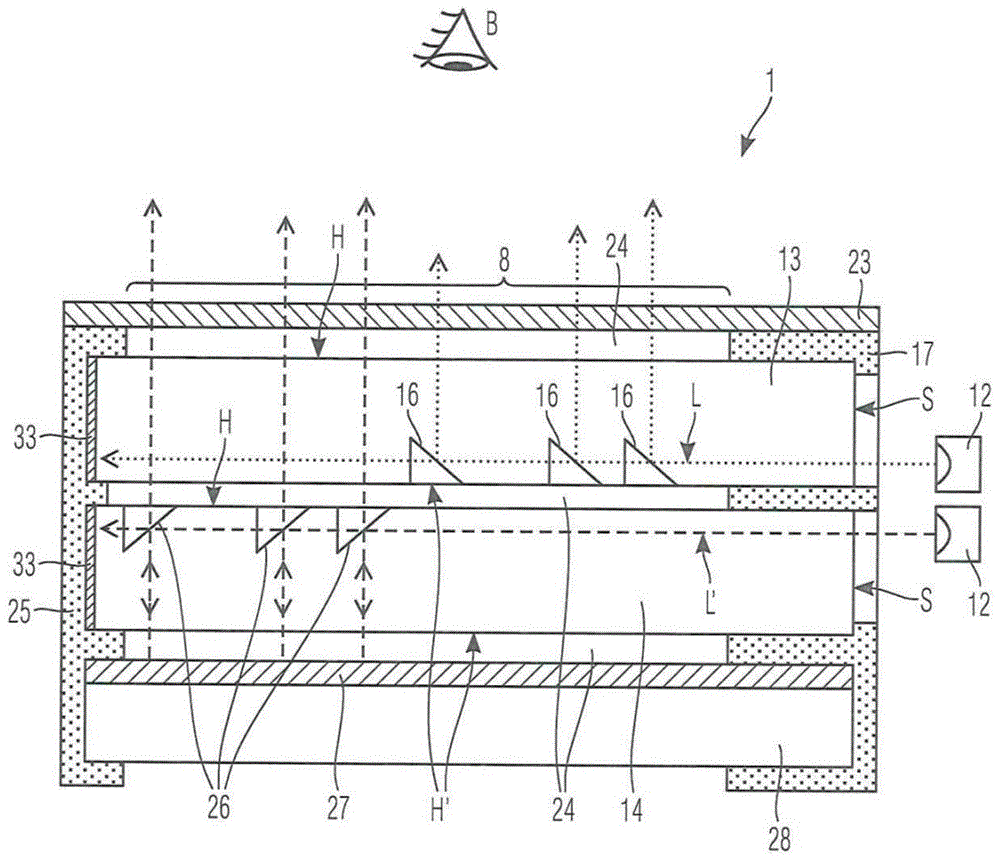
图1功能显示器1的本发明第一实施方式的示意性截面图;FIG. 1 is a schematic cross-sectional view of a first embodiment of the invention of a
图2带有功能显示器的操作元件10的本发明实施方式的示意性截面图;FIG. 2 is a schematic sectional view of an embodiment of the invention of an
图3带有包含一个功能显示器1的操作元件10的本发明方向盘的俯视图;FIG. 3 is a top view of the steering wheel according to the invention with operating
图4由两个功能显示器1、1'形成的本发明组件的水平截面图;FIG. 4 is a horizontal cross-sectional view of the assembly of the invention formed by two
图5由两个功能显示器1、1'形成的另一个本发明组件的水平截面图。FIG. 5 is a horizontal sectional view of another inventive assembly formed by two
具体实施方式detailed description
图1示意性示出功能显示器1的根据本发明的第一实施方式。功能显示器1包括外部的 透明或半透明的、但是同时并非强制且仅任选地设置的覆盖层23,所述覆盖层在功能显示器 1的按照预期的布置方式下限定面向观察者B的表面。覆盖层例如为由塑料、优选热塑料, 如聚乙烯(PE)、聚碳酸酯(PC)、聚苯乙烯(PS)、聚氯乙烯(PVC)、聚酰胺(PA)、 丙烯腈-丁二烯-苯乙烯(ABS)或聚甲基丙烯酸甲酯(PMMA),或者由玻璃材料形成的层。 覆盖层23还可以是由多个层形成的层构造的一部分。FIG. 1 schematically shows a first embodiment according to the invention of a
根据本发明,功能显示器1强制地还包括光导体叠堆,所述光导体叠堆由重叠布置的、 分别由热塑性塑料层或热塑性塑料箔形成的至少两个透明或半透明的平面状的光导体13、14 形成。光导体13、14被设置在光导体13、14之间的层24分离,所述层(在此为气隙)由具 有的折射率低于相邻光导体13、14的折射率的材料(在此为空气)形成。这个空气层24同 样设置在覆盖层23与最近相邻的光导体13之间。光导体13、14分别至少形成面向观察者B 的主面H和背离观察者的主面H',而上部的更靠近观察者B的光导体13具有背离观察者、面向在叠堆方向上的下一个相邻的光导体14的主面H'。According to the invention, the
光导体13、14分别指配有光源12,即SMD构造形式的发光二极管,所述光源被布置为 使得由其产生的光经由相对于叠堆方向侧向的端面S入射到所指配的光导体13、14中。为了 在此分别避免不希望的光散射或光辐射进入相邻的光导体13、14,设置有挡板17。在彼此对 置的端面处,在光导体13、14的端面上施加减反射涂层33,以便使相应光导体13、14中的 反向反射最小化,而光导体13、14被形状配合地固定在框架25中。在光导体13的至少一个 主面中,在此在背离观察者的主面H'中通过压印或成形引入了多个单一的微结构16,所述微 结构负责使入射到光导体13中的光L从相应的光导体13通过光折射和/或光散射向观察者B 的方向上出射并且限定包括微结构16的微结构化的符号区域。这个符号区域单独地或以与其 他符号区域光学协作的方式再次产生符号的形状,在相关的光源12对应地激活的情况下所述 符号对于观察者B而言是以发光可见的。The
微结构16形成为彼此形状相同并且具有在1至25μm范围内的最大直径。远离观察者 B的光导体14在其面向观察者B的主面H中同样具有微结构26,所述微结构同样是单一的并且形成为彼此形状相同。这些微结构也通过压印或成形被引入到光导体14的相关的主面、 在此为面向观察者B的主面H中。这些将入射到光导体14中的光L'在反射镜27的方向上耦 合,所述反射镜布置在由光导体13、14形成的光导体叠堆的背离观察者B的侧面上,在此所述反射镜呈在透明塑料层28上的部分透射的金属气相涂层的形式,所述反射镜在此通过气 隙24间隔开地与光导体14间隔开地布置,替代地还可以设想邻接光导体14的布置方式。The
只有通过反射镜27的反射,原本入射到光导体14中的光L'才被反射到观察者B的方向 上。由此,在观察者B处,依据光源12的激活可以通过不同的显示平面来实现深度效果或 者甚至实现所显示符号的立体印象。在一种设计方案中,这例如通过光导体叠堆的下部光导 体14的利用反射镜的符号区域显示以及上部光导体的绕过反射镜的相同的符号区域显示的 同时显示来实现,其中符号区域的视差偏移对于双眼观察者而言产生所显示符号的三维性质 的错觉。The light L' originally incident on the
通过在另一个设计方案中例如以时间顺序在光导体叠堆的下部光导体14的利用反射镜 的符号显示与上部光导体13的绕过反射镜的符号显示之间切换,还可以将观察者的注意力吸 引到功能显示器1上,这是通过改变功能显示1的显示平面来实现的。通过选择性激活光源, 可以相对简单地将不同的开光状态或开关功能视觉化。功能显示器1可以简单且成本低廉地 实现并且给设计者带来了很大的设计空间,这还涉及功能显示器1的摆放方式。功能显示器 表现出几乎不受光辐射影响的老化现象并且是相对节能的。微结构化的符号区域例如单独地 或与其他符号区域一起将符号以阳文方式作为图像、作为其相反的图示或者作为其轮廓再现。 先前提及的深度效果例如可以通过光导体13、14之间的距离、例如气隙厚度来设定。所述距 离例如在1至3mm的范围内。In another refinement, for example, switching between the symbol display of the
所有光导体13、14在微结构化的区域之外都是透明的。由于反射镜17还设有部分透光 性,显示面8的一大部分是光学透过的,使得例如保证了穿过功能显示器的透视,以便给予 观察者B穿过功能显示器跟踪其他显示器或道路走向的可能性。由此,例如可以将功能显示 器1摆放在方向盘处,例如在方向盘毂与方向盘圈之间的区域中,而不影响对仪表盘的观看。 在垂直于所有光导体13、14的微结构化的区域观察显示面8时,各个光导体13、14的投影 的微结构化的符号区域不重叠,以免影响符号的显示质量。All light guides 13 , 14 are transparent outside the microstructured regions. Since the
图2示出了本发明的操作元件1的实施方式。这个操作元件具有支腿3,用于将操作元 件1固定在车辆部件如仪表盘、乘客舱室的衬板或尤其机动车辆方向盘的方向盘圈11处。本 发明的操作元件10还具有限定操作面9的操作部件2,所述操作部件被形成为至少一个自支 撑的杠杆臂。自支撑的杠杆臂分别在一侧上借助于固体铰接件4支承在支腿3处,以便在垂 直于操作面9作用的致动力作用下能够使操作部件2抵抗复位力相对于支腿3围绕假想的枢 转轴线A枢转。复位力例如由固体铰接件4的变形产生。FIG. 2 shows an embodiment of the
根据本发明还设置有器件6,以便检测操作部件2与支腿3之间的枢转度。固体铰接件4 仅通过支腿3与操作部件2之间的一体式连接形成。本发明的操作元件1尤其适合于如下的 设计方案,其中从图2中所示的未致动的休止位置起围绕假想枢转轴线A到最大可能的经致 动的枢转位置的最大枢转度小于10°、优选小于5°。According to the invention, means 6 are also provided in order to detect the degree of pivoting between the operating part 2 and the leg 3 . The solid hinge 4 is formed only by the one-piece connection between the leg 3 and the operating part 2 . The
根据本发明还设置有可以由未展示的操控电子装置用操控电信号加载的致动器5,以便 产生主动触觉反馈(还被称为可触觉感知的输出),其中致动器5优选仅仅固定在操作部件 2处。致动器5优选为基于惯性的、基于电机的致动器,如在其旋转的驱动轴上固定有相对 于其重心偏心安装的质量体的电机或者磁体线圈致动器或者压电致动器或者线性宽带致动器 如柱塞线圈致动器(英文名称:Voice-Coil-Actuator,音圈致动器)或线性共振致动器。致 动器5优选通过力配合或材料配合连接固定在操作部件2处,例如通过拧接或粘合。由于仅 仅固定在操作部件2处,防止了结构噪声输入到方向盘圈11中以及因此输入到车辆部件中, 或者至少使其最小化。According to the invention there is also provided an actuator 5 which can be acted upon with an electrical control signal by control electronics not shown in order to generate an active tactile feedback (also called tactile output), wherein the actuator 5 is preferably only fixed at operating part 2. The actuator 5 is preferably an inertia-based, motor-based actuator, such as an electric motor with a mass mounted eccentrically with respect to its center of gravity fixed on its rotating drive shaft or a magnet-coil actuator or a piezoelectric actuator Or a linear broadband actuator such as a plunger coil actuator (English name: Voice-Coil-Actuator, voice coil actuator) or a linear resonant actuator. The actuator 5 is preferably fastened to the operating part 2 by a force-fit or material-fit connection, for example by screwing or gluing. Due to the fastening at the operating part 2 only, the input of structure-borne noise into the
检测枢转度的器件6被形成为电容式、光学式和/或电感式地检测支腿3与操作部件2之 间的枢转度。由于通过固体铰接件4实现的操作部件2的无间隙支承与优选无接触检测枢转 度的器件6的协作,获得了对致动力的低迟滞至无迟滞的检测,所述致动力例如被设置为用 于触发开关功能或控制功能或至少可光学、声学或触觉感知的输出的输出。The means 6 for detecting the degree of pivoting is formed to capacitively, optically and/or inductively detect the degree of pivoting between the leg 3 and the operating part 2 . Due to the play-free bearing of the operating part 2 by means of the solid hinge 4 in cooperation with the means 6 for preferably contactless detection of the degree of pivoting, a low-to-hysteresis-free detection of the actuation force, for example set An output for triggering a switching function or a control function or at least an optically, acoustically or tactilely perceivable output.
操作面9由功能显示器1的透明覆盖层23提供,所述覆盖层覆盖功能显示器1的显示面 8。功能显示器1被形成为部分透明的,以便保证观察者或操作者不受妨碍地透过功能显示器 1观看位于其下的操作区域,如仪表盘的仪表。根据本发明,功能显示器1还包括光导体叠 堆,所述光导体叠堆由重叠布置的、分别由热塑性塑料箔形成的三个透明或半透明的平面状 的光导体13、14、15形成。光导体13、14、15分别被光导体13、14、15之间设置的空气层 24分离,所述空气层因此分别形成光导体13、14、15中的两个相邻的光导体之间的气隙。 这个空气层24同样设置在覆盖层23与最近相邻的光导体13之间。The operating surface 9 is provided by a
光导体13、14、15分别至少形成面向观察者B的主面H,而上部的更靠近观察者B的这两个光导体13、14分别具有背离观察者、面向在叠堆方向上的下一个相邻的光导体14或15的主面H'。光导体13、14、15分别指配有光源12,即SMD构造形式的发光二极管,所 述光源被布置为使得由其产生的光经由相对于叠堆方向侧向的端面入射到所指配的光导体13、14、15中。为了在此分别避免不希望的光散射或光辐射进入相连的光导体13、14、15,设置有挡板17。在彼此对置的端面25处,在光导体13、14、15的端面上施加减反射涂层25,以 便使相应光导体13、14、15中的反向反射最小化。在光导体(在此为光导体13、14)的主 面中的至少一个主面中通过压印引入由多个微结构16形成的、微结构化的符号区域,这使得 光从相应的光导体13、14向观察者B的方向出射。微结构16形成为分别形状相同并且具有 在1至25μm范围内的直径。光导体14以及光导体15还具有多个微结构26。The light guides 13 , 14 , 15 each form at least a main face H facing the observer B, while the upper two
远离观察者B的下部光导体15和中部光导体14在其面向观察者B的主面H中同样具有 微结构26,所述微结构同样是单一的并且形成为彼此形状相同。这些微结构也通过压印或成 形被引入到相应光导体14、15的相关的主面、在此为面向观察者B的主面H中。这个主面 向反射镜27的方向上耦合入射到相应光导体14、15中的光,所述反射镜布置在由光导体13、 14、15形成的光导体叠堆的背离观察者B的侧面上,在此所述反射镜呈在透明塑料层28上 的反向部分透射的金属气相涂层的形式,所述反射镜在此邻接下部光导体15,替代地还可以 设想与光导体15间隔开的布置方式。只有通过反射镜27的反射,原本入射到光导体14中的 光被反射到观察者B的方向上。由此,在观察者B处,依据光源12的激活可以通过不同的 显示平面来实现深度效果或者甚至实现所显示符号的立体印象。在一种设计方案中,这例如 通过光导体叠堆的下部光导体14的利用反射镜的符号区域显示以及上部光导体的绕过反射 镜的相同的符号区域显示的同时显示来实现,其中符号区域的视差偏移使双眼观察者相信所 显示符号的三维性质。通过在另一个设计方案中例如以时间顺序在光导体叠堆的光导体14、 15的利用反射镜的符号显示与光导体13、14的绕过反射镜的符号显示之间切换,还可以将 观察者的注意力吸引到功能显示器1上,这是通过改变功能显示1的显示平面来实现的。通 过选择性激活光源,可以相对简单地将不同的开光状态或开关功能视觉化。功能显示器1可 以简单且成本低廉地实现并且给设计者带来了很大的设计空间,这还涉及功能显示器1的摆 放方式。功能显示器表现出几乎不受光辐射影响的老化现象并且是相对节能的。微结构化的 符号区域例如单独地或与其他符号区域一起将符号以阳文方式作为图像、作为其相反的图示 或者作为其轮廓再现。先前提及的深度效果例如可以通过光导体13、14、15之间的距离、例 如气隙厚度来设定。所述距离例如在1至3mm的范围内。The lower
所有光导体13、14、15在微结构化的区域之外都是透明的,使得显示面8的一大部分保 持透明并且例如保证了穿过功能显示器1的透视,以便给予观察者B穿过功能显示器跟踪其 他显示器或道路走向的可能性。由此,例如可以将功能显示器1摆放在方向盘处,例如在方 向盘毂与方向盘圈之间的区域中,而不影响对仪表盘的观看。在垂直观察显示面8时,光导 体13、14、15的微结构化的符号区域至少部分重叠,以便通过使用具有不同颜色光辐射的光 源12来产生多种颜色的符号,所述符号可以通过同时完全照亮多个光导体13、14、15而变 得可见。为了尤其在外来光作用时避免在相应的光导体13、14、15中不希望的光传播,每一 个光导体13、14、15在端面中的至少一个端面处、优选在不面向光源12的端面处具有减反 射涂层33,所述减反射涂层通常还被称为抗反射涂层或补偿层。减反射涂层的任务是,例如 通过在涂层33中吸收光,相对于未涂覆的端面来减少在经涂覆端面处被反射到光导体中的光 的量。可以接近环绕式地施加这个涂层33。这个减反射涂层33例如具有在数值上介于空气 与光导体13、14、15的材料之间的光学折射率。光导体13、14、15的分别背离光源12的末 端分别材料配合地固定在框架25中。All light guides 13, 14, 15 are transparent outside the microstructured area, so that a large part of the
如图3中所示,本发明还涉及一种方向盘20。方向盘20具有覆盖方向盘毂的缓冲器22、 至少一个方向盘辐条21和由所述方向盘辐条21承载的方向盘圈11。本发明的方向盘20还 具有功能显示器1,所述功能显示器是紧固在方向盘20处的操作元件10的组成部分并且被 整合到操作部件2中,所述操作部件可枢转运动地支承在操作元件10的支腿处。在此,操作 元件10的支腿防旋转地固定在方向盘圈11处。功能显示器1的大体上透明的显示面8被布 置在方向盘圈11与方向盘毂或方向盘20的覆盖方向盘毂的缓冲器22之间。在选择性激活属 于功能显示器1的光源时,取决于这种选择,在显示面8的区域中的不同符号18变得对于观 察者(也就是说驾驶员)可见,而由于功能显示器1在其余区域中的透明度,对于驾驶员而 言位于方向盘20后方的仪表盘或其仪表是可见的。As shown in FIG. 3 , the invention also relates to a steering wheel 20 . The steering wheel 20 has a damper 22 covering the steering wheel hub, at least one steering wheel spoke 21 and a steering wheel rim 11 carried by said steering wheel spoke 21 . The steering wheel 20 according to the invention also has a
图4示出穿过由多个功能显示器1、1'形成的本发明组件的截面图,这些功能显示器例如 分别具有如在图1、4或5中所示的截面构造并且从观察者的视角来看彼此并排布置,以便由 此形成彼此并排布置的显示面8、8'。这种布置方式的独特之处在于,一个功能显示器1的至 少一个光导体13一体式地与另一个功能显示器1'的光导体13'一体式形成,以便形成共用的 光导体。在此未示出且位于其下的其他光导体以对应地相同的尺寸形成。但是根据本发明还 应包括如下实施方式,其中每一个功能显示器1、1'的光导体形成为在其外部尺寸方面有所不 同。为了使从一个功能显示器1向另一个功能显示器1'中以及逆向的相互的光入射最小化, 在共用的光导体13、13'中形成锥形的中断部29,所述中断部用具有比共用的光导体13、13' 的材料的折射率更小的折射率的材料填充。在此,光导体13、13'的端面中的一些端面设置有 减反射涂层33。FIG. 4 shows a sectional view through an assembly according to the invention formed by a plurality of
图5示出穿过由多个功能显示器1、1'形成的本发明另一个组件的截面图,这些 功能显示器例如分别具有如在图1、4或5中所示的截面构造并且从观察者的视角来 看彼此并排布置,以便由此形成彼此并排布置的显示面8、8'。这种布置方式的独特 之处同样在于,一个功能显示器1的至少一个光导体13一体式地与另一个功能显示 器1'的光导体13'一体式形成,以便形成共用的光导体。在此未示出且位于其下的其 他光导体以对应地相同的尺寸形成。但是根据本发明还应包括如下实施方式,其中每 一个功能显示器1、1'的光导体形成为在其外部尺寸方面有所不同。为了使从一个功 能显示器1向另一个功能显示器1'中以及逆向的相互的光入射最小化,从图4可知, 在共用的光导体13、13'中形成锥形的中断部,所述中断部用具有比共用的光导体13、 13'的材料的折射率更小的折射率的材料填充。在图5中示出的实施方式中省去了这个 锥形的中断部。在其中示出的实施方式中,相应的光导体13、13'在从光源12、12' 到相关的符号18、18'的相应光走向中分别形成弯曲的界面30、32,以便形成光学有 效的、优选聚焦型的透镜元件。例如在光导体13中,在光导体13的外部端面中设置 有相对于光导体凹形的入射面30,相反,光导体13'具有多个中断部31,所述中断部 用具有比共用的光导体13、13'的材料的折射率更小的折射率的材料填充。由中断部 31形成的透镜元件同样以聚焦方式作用于从光源12'到相关的符号18'的光走向。在此, 光导体13、13'的端面中的一些端面设置有减反射涂层33。FIG. 5 shows a cross-sectional view through another assembly of the invention formed by a plurality of
Claims (17)
Applications Claiming Priority (2)
| Application Number | Priority Date | Filing Date | Title |
|---|---|---|---|
| DE102021114524.4A DE102021114524B3 (en) | 2021-06-07 | 2021-06-07 | Function display for the selective display of at least one symbol representing a switching function and/or a plurality of switching states with optical depth effect and associated operating element |
| DE102021114524.4 | 2021-06-07 |
Publications (2)
| Publication Number | Publication Date |
|---|---|
| CN115503473A true CN115503473A (en) | 2022-12-23 |
| CN115503473B CN115503473B (en) | 2025-02-21 |
Family
ID=83806460
Family Applications (1)
| Application Number | Title | Priority Date | Filing Date |
|---|---|---|---|
| CN202210550286.5A Active CN115503473B (en) | 2021-06-07 | 2022-05-20 | Function displays and associated operating elements with selectively displayed symbols |
Country Status (2)
| Country | Link |
|---|---|
| CN (1) | CN115503473B (en) |
| DE (1) | DE102021114524B3 (en) |
Families Citing this family (3)
| Publication number | Priority date | Publication date | Assignee | Title |
|---|---|---|---|---|
| DE102023116253A1 (en) | 2023-06-21 | 2024-12-24 | Valeo Schalter Und Sensoren Gmbh | Motor vehicle component with backlit symbol and with homogeneous illumination achieved by a light guide and motor vehicle |
| TWM663688U (en) * | 2024-07-01 | 2024-12-01 | 閎暉實業股份有限公司 | Illuminating assembly |
| DE102024129010A1 (en) * | 2024-10-08 | 2026-04-09 | Audi Aktiengesellschaft | Display system |
Citations (8)
| Publication number | Priority date | Publication date | Assignee | Title |
|---|---|---|---|---|
| EP0045831A1 (en) * | 1980-08-08 | 1982-02-17 | VDO Adolf Schindling AG | Passive display device |
| DE102010043715A1 (en) * | 2010-11-10 | 2012-05-10 | Bayerische Motoren Werke Aktiengesellschaft | bar display |
| CN103384613A (en) * | 2010-12-24 | 2013-11-06 | 大众汽车有限公司 | Motor vehicle display device |
| CN206584144U (en) * | 2015-11-06 | 2017-10-24 | 普瑞有限公司 | display device with multiple backlight symbols |
| CN108292062A (en) * | 2015-11-27 | 2018-07-17 | 矽光学有限公司 | Displays for free-running and restricted-running modes |
| WO2019214926A1 (en) * | 2018-05-07 | 2019-11-14 | Volkswagen Aktiengesellschaft | Operating and/or display element for a motor vehicle |
| CN110789446A (en) * | 2018-08-01 | 2020-02-14 | 诺维汽车内饰设计有限责任公司 | Molded part and method for producing such a molded part |
| CN111301166A (en) * | 2018-12-12 | 2020-06-19 | 罗伯特·博世有限公司 | Projection equipment |
Family Cites Families (4)
| Publication number | Priority date | Publication date | Assignee | Title |
|---|---|---|---|---|
| US5359503A (en) | 1991-06-24 | 1994-10-25 | Mitsubishi Denki Kabushiki Kaisha | Surface luminous lighting unit |
| DE102011016001A1 (en) | 2011-04-04 | 2012-10-04 | Audi Ag | Lighting device for a motor vehicle with light-guiding elements |
| DE102015007610B4 (en) | 2015-06-13 | 2018-05-24 | Daimler Ag | Lighting device for segmented lighting, in particular for ambient lighting in the interior of a vehicle |
| DE102017217162A1 (en) | 2017-09-27 | 2019-03-28 | Bayerische Motoren Werke Aktiengesellschaft | Interior assembly for a motor vehicle and method for manufacturing an interior assembly |
-
2021
- 2021-06-07 DE DE102021114524.4A patent/DE102021114524B3/en active Active
-
2022
- 2022-05-20 CN CN202210550286.5A patent/CN115503473B/en active Active
Patent Citations (8)
| Publication number | Priority date | Publication date | Assignee | Title |
|---|---|---|---|---|
| EP0045831A1 (en) * | 1980-08-08 | 1982-02-17 | VDO Adolf Schindling AG | Passive display device |
| DE102010043715A1 (en) * | 2010-11-10 | 2012-05-10 | Bayerische Motoren Werke Aktiengesellschaft | bar display |
| CN103384613A (en) * | 2010-12-24 | 2013-11-06 | 大众汽车有限公司 | Motor vehicle display device |
| CN206584144U (en) * | 2015-11-06 | 2017-10-24 | 普瑞有限公司 | display device with multiple backlight symbols |
| CN108292062A (en) * | 2015-11-27 | 2018-07-17 | 矽光学有限公司 | Displays for free-running and restricted-running modes |
| WO2019214926A1 (en) * | 2018-05-07 | 2019-11-14 | Volkswagen Aktiengesellschaft | Operating and/or display element for a motor vehicle |
| CN110789446A (en) * | 2018-08-01 | 2020-02-14 | 诺维汽车内饰设计有限责任公司 | Molded part and method for producing such a molded part |
| CN111301166A (en) * | 2018-12-12 | 2020-06-19 | 罗伯特·博世有限公司 | Projection equipment |
Also Published As
| Publication number | Publication date |
|---|---|
| CN115503473B (en) | 2025-02-21 |
| DE102021114524B3 (en) | 2022-11-17 |
Similar Documents
| Publication | Publication Date | Title |
|---|---|---|
| CN115503473A (en) | Function display and associated operating elements for optionally displaying at least one symbol representing a switching function and/or a plurality of switching states | |
| JP6101235B2 (en) | Vehicle display device | |
| CN114531863A (en) | Function display for selectively displaying icons representing switch functions and/or switch states | |
| JP6215917B2 (en) | In-vehicle display device | |
| CN103163711A (en) | Projection device and method for projecting image into visual range of vehicle driver | |
| WO2018083217A1 (en) | Display arrangement | |
| WO2018168188A1 (en) | Display panel | |
| WO2016031537A1 (en) | Molded resin article and display device for vehicle | |
| JP4887822B2 (en) | Pointer instrument | |
| US7278748B2 (en) | Display apparatus | |
| JP2012108470A (en) | Head-up display device | |
| JP2015087379A (en) | Display apparatus | |
| CN219133858U (en) | Functional display, operating element and steering wheel for a motor vehicle | |
| JP6210425B2 (en) | Head-up display device | |
| CN115508937B (en) | A functional display and related manufacturing method that selectively displays at least one symbol representing a switching function and/or multiple switching states. | |
| US11921313B2 (en) | Function display for selectively displaying symbols representing switching functions and/or switching states with a reduced veiling glare | |
| DE102022123611B3 (en) | Function display for selective optical display with holographic image carrier and control element | |
| CN118434585A (en) | Operating element or visual element with a laterally oriented holographic functional display for visualizing a switching function assigned to the operating element or visual element and/or its corresponding switching state | |
| JP2007206427A (en) | Display board | |
| JP2003237413A (en) | Pointer instrument for vehicles | |
| JP2008310185A (en) | Display device | |
| JP4508695B2 (en) | Instrument display | |
| US20250388082A1 (en) | Display device for a vehicle and associated manufacturing method | |
| CN116736431A (en) | Function display for selective display of several symbols | |
| JP2021084239A (en) | Decorative laminate, decorative laminate-bearing display device and decorative laminate having acoustic function |
Legal Events
| Date | Code | Title | Description |
|---|---|---|---|
| PB01 | Publication | ||
| PB01 | Publication | ||
| SE01 | Entry into force of request for substantive examination | ||
| SE01 | Entry into force of request for substantive examination | ||
| GR01 | Patent grant | ||
| GR01 | Patent grant |