Disclosure of Invention
Aiming at the problems, the invention aims to provide a multi-vertebral body combined constraint optimal trajectory planning method and device for pedicle screws, the method provides an effective method for determining a screw-in point range and designing a connecting rod for multi-vertebral body combined screw placement, and can accurately and quickly calculate a clinically effective three-dimensional placement path of the pedicle screws
In order to realize the purpose, the invention adopts the following technical scheme:
the invention relates to a multi-vertebral body combined constraint pedicle screw optimal trajectory planning method, which comprises the following steps:
determining a safe screw placing area of each vertebral body screw placing, and acquiring an in-point range of a screw track on each vertebral body;
calculating the optimal form of the connecting rod by utilizing the range of the entry point of the screw on each vertebral body;
determining the moving range of the multi-axis nail cap;
and forming a constraint condition of a clinically effective screw placing track by utilizing the avoidance area of the vertebral body screw placing, the position of the connecting rod and the moving range of the multi-axis screw cap, and then determining the optimal track of the pedicle screw of each vertebral body under the combined constraint condition.
The optimal path planning method for the multi-vertebral body combined constraint pedicle screw preferably determines a safe screw placing area of each vertebral body screw placing, and the acquisition of the range of an entry point of the screw path on each vertebral body is realized by the following method:
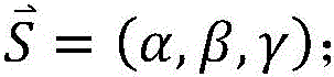
the optimal path of the pedicle screw is as follows:
the safe screw-placing area of the vertebral body screw-placing is as follows:
where M is a point on the avoidance region, M
0 A nail insertion point for an optimal screw trajectory; rho is the safe distance from the screw to the avoidance area, and rho is greater than 0;
is a unit direction vector of the screw trajectory;
any is denoted for a special symbol;
carrying out radial transformation on the formula (2) to simplify the formula into a cylinder taking the optimal screw track as a central line, specifically:
z 2 +Y 2 =(d-ρ) 2 (4)
0≤X≤L
wherein,
an orthogonal unit vector of (α, β, γ);
an orthogonal unit vector of (α, β, γ);
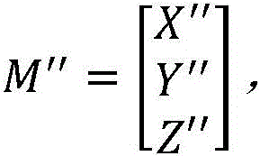
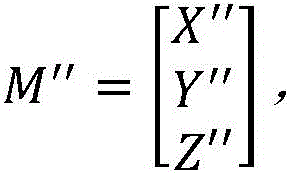
is a spatial transformation matrix; l is the screw length;
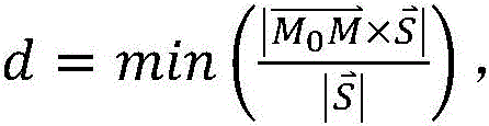
the shortest distance from the optimal screw track to the avoidance area is obtained;
a safe nail placing area; rho is the safe distance from the screw to the avoided area; l is the screw length; x, Y, Z is the original coordinate;
the range of the nail penetration point of the screw track is as follows:
z 2 +Y 2 =(d-ρ) 2 (6)
wherein,
is the range of the nail penetration point of the screw track.
According to the optimal path planning method for the pedicle screw of the multi-vertebral body combined constraint, preferably, the optimal shape of the connecting rod is a curve which accords with the natural bending shape of the spine and is positioned on a plane which is as close to the optimal screw path directions on all the same sides as possible; the shape of the optimal connecting rod comprises the position and the shape thereof, and specifically comprises the following steps:
let M 0 (x, y, z) is the optimal screw track entry point position on all vertebral bodies ipsilateral, then the optimal connecting rod position is expressed as:
AX+BY+CZ+D=0 (7)
thus, the optimal screw trajectory under the constraint of the connecting rod is expressed as:
wherein,
A. b, C, D is the parameter of the plane where the connecting rod is located; l' is the length of the nail cap; (alpha
nut ,β
nut ,γ
nut ) Is a unit direction vector of the nail cap; omega is the maximum included angle which can be formed between the nail cap and the nail;
let the best plane of the known connecting rod be P:
AX+BY+CZ+D=0 (11)
by taking the plane as an XOZ plane, a new space coordinate system { i }can be constructed T ,j T ,k T And then:
wherein N is
0 、N
x And N
z Is a point on the optimal plane P, and
perpendicular to
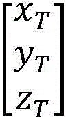
The coordinates of the nut on the optimal plane P are:
wherein,
to be composed of
Coordinate conversion to
A spatial transformation matrix on the coordinates;
for the head of the nail in a spatial coordinate system i
T ,j
T ,k
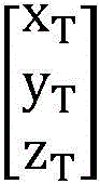
T Coordinates under }; since, the best plane P is defined as the space coordinate system { i }
T ,j
T ,k
T XOZ face of (i) }, then y
T =0, therefore, the shape of the connecting rod is found by a least-squares fit:
in summary, the optimal position and shape of the connecting rod are obtained as follows:
wherein x is
Tl And z
Tl The coordinates of the nail cap in the new coordinate system; x is the number of
ol 、y
ol And z
ol The coordinates of the nail cap under the original coordinate system are obtained;
the curve parameters of the curve on which the nail head is positioned.
The optimal trajectory planning method for the multi-vertebral body combined constraint pedicle screw is preferably realized by determining the moving range of the screw cap of the multi-axis screw in the following modes:
and if the length of the screw cap of the screw is L', the parameter equation of the screw cap is expressed as follows:
(x,y,z)=t(α nut ,β nut ,γ nut )+M nut (19)
s.t.0<t<L′
wherein (alpha) nut ,β nut ,γ nut ) Is a unit direction vector of the nail head, M nut T represents the unknown number of the length of the nail head as the position of the nail head;
the movable range of the nail cap is as follows:
wherein
Is the unit direction vector of the screw; m
0 A nail insertion point for an optimal screw trajectory; omega is the maximum movable included angle between the screw cap and the screw.
The invention relates to a multi-vertebral body combined constraint pedicle screw optimal trajectory planning device, which comprises:
the first processing unit is used for determining a safe screw placing area of each vertebral body screw placing and acquiring an in-point range of a screw track on each vertebral body;
the second processing unit is used for calculating the optimal form of the connecting rod by utilizing the range of the entry point of the screw on each vertebral body;
the third processing unit is used for determining the moving range of the multi-axis nail cap;
and the fourth processing unit is used for forming a constraint condition of a clinically effective screw placing track by utilizing the avoidance area of the vertebral body screw placing, the position of the connecting rod and the moving range of the multi-axis screw cap, and then determining the optimal track of the pedicle screw of each vertebral body under the combined constraint condition.
The computer storage medium of the invention stores a computer program thereon, and the computer program is executed by a processor to realize the optimal path planning method steps of the pedicle screw with multi-vertebral body combined constraint.
The computer equipment comprises a memory, a processor and a computer program which is stored on the memory and can run on the processor, wherein the processor realizes the optimal path planning method steps of the pedicle screw with multi-vertebral body combined constraint when executing the computer program.
Due to the adoption of the technical scheme, the invention has the following advantages:
the invention provides an effective method for determining the range of the screw inserting point and the design of the connecting rod for the combined screw inserting of multiple vertebral bodies, and can accurately and quickly calculate the clinical effective three-dimensional inserting path of the pedicle screw.
Detailed Description
Exemplary embodiments of the present invention will be described in more detail below with reference to the accompanying drawings. While exemplary embodiments of the invention are shown in the drawings, it should be understood that the invention can be embodied in various forms and should not be limited to the embodiments set forth herein. Rather, these embodiments are provided so that this disclosure will be thorough and complete, and will fully convey the scope of the invention to those skilled in the art.
The invention provides a multi-vertebral body combined constraint optimal trajectory planning method for pedicle screws, which comprises the steps of determining a safe region for placing screws on each vertebral body, and obtaining an entry point range of the trajectory of the screws on each vertebral body; calculating the clinical effective position of the connecting rod by using the range of the entry point of the screw on each vertebral body; determining the moving range of the multi-axis nail cap; and forming constraint conditions of an optimal screw placing track by utilizing the avoidance area of the vertebral body screw placing, the position of the connecting rod and the moving range of the multi-axis screw cap, and then calculating the effective screw track of each vertebral body under the combined constraint conditions. The invention provides an effective method for determining the range of the screw inserting point and the design of the connecting rod for the combined screw inserting of multiple vertebral bodies, and can accurately and quickly calculate the clinical effective three-dimensional inserting path of the pedicle screw.
The invention provides a multi-vertebral body combined constraint pedicle screw optimal trajectory planning method, which comprises the following steps:
s1, determining a safe screw placing area of each vertebral body screw placing, and acquiring an in-point range of a screw track on each vertebral body;
s2, calculating the optimal form of the connecting rod by using the range of the entry point of the screw on each vertebral body;
s3, determining the moving range of the multi-axis nail cap;
and S4, forming a constraint condition of a clinically effective screw placing track by utilizing the evaded area of the vertebral body screw placing, the position of the connecting rod and the moving range of the multi-axis screw cap, and then determining the optimal track of the pedicle screw of each vertebral body under the combined constraint condition.
In the above embodiment, preferably, the safe screw-placing area of each vertebral body screw-placing is determined, and the range of the point of entry of the screw track on each vertebral body is obtained by:
the optimal path of the pedicle screw is as follows:
the safe screw-placing area of the vertebral body screw-placing is as follows:
where M is a point on the avoidance region, M
0 A nail insertion point for an optimal screw trajectory; rho is greater than 0 and is the safe distance from the screw to the avoidance area;
a unit direction vector of the screw trajectory;
any is denoted for a special symbol;
for the safety of nail placement and the simplicity of calculation, the formula (2) can be subjected to radial transformation to simplify the transformation into a cylinder taking the optimal screw track as a central line, specifically:
z 2 +Y 2 =(d-ρ) 2 (4)
0≤X≤L
wherein,
an orthogonal unit vector of (α, β, γ);
an orthogonal unit vector of (α, β, γ);
is a spatial transformation matrix; l is the screw length;
the shortest distance from the optimal screw track to the avoidance area is obtained;
a safe nail placing area; rho is the safe distance from the screw to the avoidance zone; l is the screw length; x, Y, Z is the original coordinate;
wherein, the nail penetration point range of screw track is:
z 2 +Y 2 =(d-p) 2 (6)
wherein,
is the range of the nail penetration point of the screw track.
In the above embodiment, preferably, the optimal configuration of the connecting rod is a curve conforming to the natural curvature configuration of the spine and lying as close as possible to the plane in the direction of the optimal trajectory of the screws on all ipsilateral sides; the form of the optimal connecting rod comprises the position and the shape thereof, and specifically comprises the following steps:
let M 0 (x, y, z) is the optimal screw trajectory entry point position for all vertebras ipsilateral, then the optimal connecting rod position can be expressed as:
AX+BY+CZ+D=0 (7)
thus, the optimal screw trajectory under the constraint of the connecting rod can be expressed as:
wherein,
A. b, C, D is the parameter of the plane where the connecting rod is located; l' is the length of the nail cap; (alpha
nut ,β
nut ,γ
nut ) Is a unit direction vector of the nail cap; the omega nail cap can form a maximum included angle with the nail;
let the best plane of the known connecting rod be P:
AX+BY+CZ+D=0 (11)
by taking the plane as an XOZ plane, a new space coordinate system { i }can be constructed T ,j T ,k T And then:
wherein N is
0 ,N
x ,N
z Is a point on the optimal plane P, the moon
Perpendicular to
The coordinates of the nut on the optimal plane P are:
wherein,
to be composed of
Coordinate conversion to
A spatial transformation matrix on the coordinates;
for the head of the nail in a spatial coordinate system i
T ,j
T ,k
T Coordinates under }; since, the optimal plane P is defined as the space coordinate system { i }
T ,j
T ,k
T XOZ face of (i) }, then y
T =0, therefore, the shape of the connecting rod can be derived by least-squares fitting:
as shown in fig. 2, the optimal position and shape of the connecting rod can be summarized as follows:
wherein x is
Tl And z
Tl The coordinates of the nail cap under the new coordinate system; x is the number of
ol 、y
ol And z
ol The coordinates of the nail cap under the original coordinate system;
the curve parameters of the curve on which the nail head is positioned.
In the above embodiment, preferably, the determination of the range of motion of the cap of the multi-axis nail is performed by:
if the length of the screw cap is L', the parameter equation of the screw cap can be expressed as follows:
(x,y,z)=t(α nut ,β nut ,γ nut )+M nut (19)
s.t.0<t<L′
wherein (alpha) nut ,β nut ,γ nut ) Is a unit direction vector of the nail head, M nut T represents the unknown number of the length of the nail head as the position of the nail head;
then, as shown in fig. 1, the movable range of the nail head is:
wherein
Is the unit direction vector of the screw; m
0 A nail insertion point for an optimal screw trajectory; omega is the maximum movable included angle between the screw cap and the screw.
The invention also provides a multi-vertebral body combined constraint optimal trajectory planning device for the pedicle screws, which comprises:
the first processing unit is used for determining a safe screw placing area of each vertebral body screw placing and acquiring an in-point range of a screw track on each vertebral body;
the second processing unit is used for calculating the optimal form of the connecting rod by utilizing the range of the entry point of the screw on each vertebral body;
the third processing unit is used for determining the moving range of the multi-axis nail cap;
and the fourth processing unit is used for forming a constraint condition of a clinically effective screw placing track by utilizing the avoidance area of the vertebral body screw placing, the position of the connecting rod and the moving range of the multi-axis screw cap, and then determining the optimal track of the pedicle screw of each vertebral body under the combined constraint condition.
The invention also provides a computer storage medium on which a computer program is stored, wherein the computer program is executed by a processor to realize the optimal path planning method steps of the multi-vertebral body combined constraint pedicle screw.
The invention also provides computer equipment which comprises a memory, a processor and a computer program which is stored on the memory and can run on the processor, wherein the processor realizes the optimal path planning method steps of the multi-vertebral body combined constraint pedicle screw when executing the computer program.
Finally, it should be noted that: the above examples are only intended to illustrate the technical solution of the present invention, but not to limit it; although the present invention has been described in detail with reference to the foregoing embodiments, it will be understood by those of ordinary skill in the art that: the technical solutions described in the foregoing embodiments may still be modified, or some technical features may be equivalently replaced; and such modifications or substitutions do not depart from the spirit and scope of the corresponding technical solutions of the embodiments of the present invention.