CN1156110C - Transmitting and zero intermediate frequency receiving method and device in multi-carrier CDMA system based on polyphase decomposition - Google Patents
Transmitting and zero intermediate frequency receiving method and device in multi-carrier CDMA system based on polyphase decomposition Download PDFInfo
- Publication number
- CN1156110C CN1156110C CNB021004285A CN02100428A CN1156110C CN 1156110 C CN1156110 C CN 1156110C CN B021004285 A CNB021004285 A CN B021004285A CN 02100428 A CN02100428 A CN 02100428A CN 1156110 C CN1156110 C CN 1156110C
- Authority
- CN
- China
- Prior art keywords
- frequency
- carrier
- filter
- intermediate frequency
- zero
- Prior art date
- Legal status (The legal status is an assumption and is not a legal conclusion. Google has not performed a legal analysis and makes no representation as to the accuracy of the status listed.)
- Expired - Fee Related
Links
Images


Landscapes
- Digital Transmission Methods That Use Modulated Carrier Waves (AREA)
Abstract
Description
(一)技术领域:(1) Technical field:
本发明属于CDMA(码分多址)蜂窝通信系统领域,尤其涉及基于多相分解的多载波CDMA系统发送与零中频的接收方法与装置The invention belongs to the field of CDMA (Code Division Multiple Access) cellular communication systems, in particular to a multi-carrier CDMA system transmission and zero-IF reception method and device based on polyphase decomposition
(二)背景技术:(two) background technology:
CDMA蜂窝通信技术以其频率规划简单、系统容量大、抗多径能力强、通信质量好、电磁干扰小等特点显示出巨大的发展潜力,是包括第三代的未来移动通信的主流技术。其中,多载波DS-CDMA(直接序列扩频码分多址)系统具有:支持高速数据传输,较高的频带利用率,可以进行有效的频率分集和时间分集以及有效地抑制干扰等的突出优势。CDMA cellular communication technology shows great development potential due to its simple frequency planning, large system capacity, strong anti-multipath ability, good communication quality, and low electromagnetic interference. It is the mainstream technology of future mobile communication including the third generation. Among them, the multi-carrier DS-CDMA (Direct Sequence Spread Spectrum Code Division Multiple Access) system has the outstanding advantages of supporting high-speed data transmission, high frequency band utilization, effective frequency diversity and time diversity, and effective suppression of interference. .
传统的多载波DS-CDMA接收机要采用与载波个数相等的高Q值的高频模拟匹配滤波器,以分开不同载频上传输的信号;再分别将各个载波上的射频信号下变频到基带;然后分别对各个载波的信号在低频进行采样。这样的接收机需要的射频模拟电路的套数与载波的个数相等;且采样率最低为信号带宽的2倍。本发明提出只用一套模拟接收电路将各个载波信号同时从射频或高中频(高中频是指所采用的中频频率远高于调制信号带宽)下变频至基带的零中频接收方法。这里的零中频是指下变频的结果是使得多个载波的中间一个载波的中心频率为零频率。零中频接收机具有以下的优点:(1)不需要高Q值的高频匹配滤波器。但是在零中频接收机中仍然使用高频滤波器以降低对下变频动态范围的要求,并防止射频信号与本振的谐波分量的混频。(2)由于使用零中频接收,使低通滤波器很容易集成到芯片内部,且使用数字滤波器,充分发挥了数字处理的优势。(3)由于零中频信号为复信号,因此在后续的数字处理时,能够最大可能地降低对采样频率的要求,降低硬件实现的难度。(4)从软件无线电的角度来考虑,使用零中频接收机将使A/D采样后的数字处理部分及RAKE接收机可方便地设计成单片接收机,仅需一个射频处理装置和A/D转换器装置。Traditional multi-carrier DS-CDMA receivers use high-Q high-frequency analog matched filters equal to the number of carriers to separate signals transmitted on different carrier frequencies; and then down-convert the RF signals on each carrier to baseband; and then sample each carrier signal at a low frequency. The number of sets of radio frequency analog circuits required by such a receiver is equal to the number of carriers; and the minimum sampling rate is twice the signal bandwidth. The present invention proposes a zero-IF receiving method in which each carrier signal is simultaneously down-converted from a radio frequency or an IF (IF means that the frequency of the IF used is much higher than the bandwidth of the modulation signal) to the baseband by using only one set of analog receiving circuits. The zero intermediate frequency here means that the result of down-conversion is that the center frequency of a carrier in the middle of multiple carriers is zero frequency. The zero-IF receiver has the following advantages: (1) It does not require a high-Q high-frequency matched filter. However, high-frequency filters are still used in zero-IF receivers to reduce the requirements on the dynamic range of down-conversion and prevent mixing of RF signals and harmonic components of local oscillators. (2) Due to the use of zero intermediate frequency reception, the low-pass filter is easily integrated into the chip, and the digital filter is used to give full play to the advantages of digital processing. (3) Since the zero-IF signal is a complex signal, the requirement for sampling frequency can be reduced as much as possible during subsequent digital processing, and the difficulty of hardware implementation can be reduced. (4) From the perspective of software radio, the use of zero-IF receiver will make the digital processing part after A/D sampling and RAKE receiver can be easily designed as a single-chip receiver, only one radio frequency processing device and A/D D converter device.
(三)发明内容:(3) Contents of the invention:
本发明的目的是针对现有的多载波DS-CDMA系统发送与接收技术的不足,提出一种能够充分发挥数字处理能力、最大可能地降低硬件规模的实用的发送与接收技术,使得系统的实现更经济可靠。The purpose of the present invention is to address the deficiencies of the existing multi-carrier DS-CDMA system transmission and reception technology, to propose a practical transmission and reception technology that can fully utilize the digital processing capability and reduce the hardware scale as much as possible, so that the realization of the system More economical and reliable.
本发明提出了一种基于调制型滤波器组的多载波DS-CDMA系统发送与零中频接收方法及其多相分解的简化实现方法,其技术方案是:在接收端,将多载波DS-CDMA接收信号从射频或高中频下变频至基带,以使多个载波的中间一个载波的中心频率为零频率,运用最低的采样频率进行采样,以调制型滤波器组替代多载波数字滤波器,在分离多个载波接收信号并重建原各个载波上的发送信号的同时,利用多相分解简化接收机的实现结构,降低接收机的硬件实现复杂度。在发送端,同样以调制型滤波器组替代多载波数字滤波器,在将各载波预携带的信息并行经过调制型发送滤波器组的同时,利用多相分解简化发射机的实现结构,然后同时上变频到高中频或射频。The present invention proposes a multi-carrier DS-CDMA system transmission and zero-IF receiving method based on a modulated filter bank and a simplified implementation method of polyphase decomposition thereof. The technical scheme is: at the receiving end, the multi-carrier DS-CDMA The received signal is down-converted from radio frequency or high-frequency to baseband, so that the center frequency of a carrier in the middle of multiple carriers is zero frequency, and the lowest sampling frequency is used for sampling, and the multi-carrier digital filter is replaced by a modulated filter bank. While separating multiple carrier receiving signals and reconstructing the original sending signals on each carrier, polyphase decomposition is used to simplify the implementation structure of the receiver and reduce the hardware implementation complexity of the receiver. At the sending end, the multi-carrier digital filter is also replaced by a modulated filter bank. While the information pre-carried by each carrier passes through the modulated transmit filter bank in parallel, the implementation structure of the transmitter is simplified by polyphase decomposition, and then simultaneously Upconversion to IF or RF.
现结合附图说明其实现装置:Now illustrate its realization device in conjunction with accompanying drawing:
多载波DS-CDMA系统的基于调制型滤波器组的发送和零中频的接收方法及其多相分解的简化实现包括以下步骤:在接收端,将多载波信号从射频或高中频直接下变频到基带;对基带多载波接收信号进行采样;采用数字滤波器形成调制型滤波器组结构。在发送端,用数字滤波器形成调制型发送滤波器组结构;将各载波预携带的信息并行经过调制型发送滤波器组,然后同时上变频到射频或高中频。对收发两端的调制型滤波器组采用多相分解的方法进行简化实现。具体分别进行描述。The simplified implementation of the multi-carrier DS-CDMA system based on the transmission of the modulated filter bank and the reception method of zero-IF and its polyphase decomposition includes the following steps: at the receiving end, the multi-carrier signal is directly down-converted from the radio frequency or high-frequency to Baseband; sampling baseband multi-carrier received signals; using digital filters to form a modulated filter bank structure. At the transmitting end, digital filters are used to form a modulated transmit filter bank structure; the information pre-carried by each carrier is passed through the modulated transmit filter bank in parallel, and then up-converted to radio frequency or high-frequency at the same time. The modulated filter banks at the two ends of the transmitter and receiver are simplified and realized by polyphase decomposition. Each will be specifically described.
1、基于调制型滤波器组的发送与零中频的接收方法1. Transmission and zero-IF reception method based on modulated filter bank
在接收端,首先将多载波DS-CDMA的接收信号从射频或高中频下变频至基带,使得多个载波中的中间一个载波的中心频率处于零频率位置,再经过低通滤波器滤掉带外噪声。At the receiving end, the received signal of multi-carrier DS-CDMA is down-converted from radio frequency or high-frequency to baseband first, so that the center frequency of the middle carrier among the multiple carriers is at zero frequency, and then filtered out by a low-pass filter. external noise.
以cdma2000系统三载波配置cdma2000-3x为例,具体说明零中频接收实现方法。图1(a)为接收端三载波信号的频谱示意图。三个载波的中心频率分别为f1、f2、f3,它们满足Taking cdma2000 system three-carrier configuration cdma2000-3x as an example, the implementation method of zero-IF reception is explained in detail. Figure 1(a) is a schematic diagram of the frequency spectrum of the three carrier signals at the receiving end. The center frequencies of the three carriers are f 1 , f 2 , f 3 respectively, and they satisfy
f1+fΔ=f2=f3-fΔ [公式1]f 1 +f Δ =f 2 =f 3 -f Δ [Formula 1]
其中fΔ=1.23MHz。经过下变频处理和低通滤波后,得到如图1(b)所示的三载波基带信号频谱,其第二载波信号的中心频率为零。where f Δ =1.23 MHz. After down-conversion processing and low-pass filtering, the frequency spectrum of the three-carrier baseband signal shown in Figure 1(b) is obtained, and the center frequency of the second carrier signal is zero.
对图1(b)所示的三载波的零中频基带信号进行A/D采样,并将采样后的信号送入与载波个数相等的复系数数字滤波器进行处理,以分离不同载波所携带的信号,所得到的接收机称作为基于调制型滤波器组的多载波接收机结构。A/D sampling is performed on the zero-IF baseband signal of the three carriers shown in Figure 1(b), and the sampled signal is sent to a complex coefficient digital filter equal to the number of carriers for processing to separate the signals carried by different carriers. , the resulting receiver is called a multi-carrier receiver structure based on a modulated filter bank.
在发送端,将各载波预携带的信息先并行经过由与载波个数相等的复系数数字滤波器组成的调制型发送滤波器组,得到具有如图1(b)所示的频谱的基带信号;然后再同时上变频到射频或高中频。上变频后的信号具有如图1(a)所示的频谱。这样所得到的发射机称作为基于调制型滤波器组的多载波发射机结构。At the transmitting end, the information pre-carried by each carrier is passed through a modulation-type transmitting filter bank composed of complex coefficient digital filters equal to the number of carriers in parallel to obtain a baseband signal with a spectrum as shown in Figure 1(b) ; and then up-convert to RF or IF at the same time. The up-converted signal has a frequency spectrum as shown in Fig. 1(a). The resulting transmitter is called a modulated filter bank based multi-carrier transmitter structure.
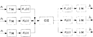
以cdma2000系统三载波配置为例,基于调制型滤波器组的发射机与零中频接收机的结构如图2所示。如果信道没有畸变,则采用此结构可以在接收端精确地重建原各个载波上的发送信号。Taking the three-carrier configuration of the cdma2000 system as an example, the structure of the transmitter and zero-IF receiver based on the modulation filter bank is shown in Figure 2. If the channel is not distorted, using this structure can accurately reconstruct the original transmitted signal on each carrier at the receiving end.
图2中p1、p2、p3分别表示各载波上的发送信息,

其中
2、接收端调制型滤波器组的简化实现2. Simplified realization of the modulated filter bank at the receiving end
设[公式3]中给出的低通原型数字滤波器冲激响应h(n)的阶数为L(对于cdma2000系统中的三载波配置,其发送端的低通原型数字滤波器阶数L取值为48。),其多相分解为:Suppose the order of the low-pass prototype digital filter impulse response h(n) given in [Equation 3] is L (for the three-carrier configuration in the cdma2000 system, the order L of the low-pass prototype digital filter at the sending end is taken as value is 48.), and its polyphase decomposition is:
其中,低通原型滤波器H(z)的第q个多相元素为:Among them, the qth polyphase element of the low-pass prototype filter H(z) is:
则各滤波器的多相分解为:Then the polyphase decomposition of each filter is:
将上式表示成两个矩阵相乘的形式:Express the above formula in the form of multiplying two matrices:
由此得到多载波DS-CDMA系统接收滤波器组的多相分解的简化实现结构,如图3所示。Thus, a simplified realization structure of the multi-phase decomposition of the receiving filter bank of the multi-carrier DS-CDMA system is obtained, as shown in FIG. 3 .
图3中的矩阵T为:The matrix T in Figure 3 is:
3、发送端调制型滤波器组的简化实现3. Simplified realization of the modulation filter bank at the sending end
同理,由图2和[公式7]可以得到多载波DS-CDMA系统发送滤波器组的多相分解的简化实现结构,如图4所示。图4中的矩阵TH表示矩阵T的共轭转置,具体取值如下:Similarly, from Figure 2 and [Equation 7], the simplified implementation structure of the polyphase decomposition of the transmit filter bank of the multi-carrier DS-CDMA system can be obtained, as shown in Figure 4. The matrix T H in Figure 4 represents the conjugate transpose of the matrix T, and the specific values are as follows:
4.计算复杂性之比较4. Comparison of Computational Complexity
以cdma2000系统三载波配置为例说明本发明在降低实现复杂度方面的优越特性。以每个输入采样处理所需的乘法累加次数作为实现复杂度的衡量标准。Taking the three-carrier configuration of the cdma2000 system as an example, the superior characteristics of the present invention in reducing the implementation complexity are illustrated. The number of multiply-accumulates required for each input sample processing is used as a measure of the complexity of the implementation.
以对于三载波接收机,若采用如图2所示的结构加以实现,则对于每个输入采样所需的乘法累加次数为3L。若采用如图4所示的多相分解简化接收结构,则由于所有的滤波运算仅需在1/M倍采样速率上进行,且M个滤波器为低通原型滤波器的多相元素,其总长度为L。考虑到如[公式8]所示的运算矩阵T无需乘法运算,因而对于每个采样输入信号,图4所示的多相分解接收结构所需的乘法累加次数为:L次乘法累加运算与12次加法运算。由此可知,基于多相分解的接收机结构可以使实现复杂度在图2所示的接收结构的基础上降低约3M=12倍。For a three-carrier receiver, if the structure shown in Figure 2 is used to implement, the number of times of multiplication and accumulation required for each input sample is 3L. If the polyphase decomposition shown in Figure 4 is used to simplify the receiving structure, since all filtering operations only need to be performed at 1/M times the sampling rate, and the M filters are polyphase elements of the low-pass prototype filter, the The total length is L. Considering that the operation matrix T shown in [Equation 8] does not require multiplication, so for each sampled input signal, the number of times of multiplication and accumulation required by the polyphase decomposition receiving structure shown in Figure 4 is: L multiplication and accumulation operations and 12 addition operation. It can be seen that the receiver structure based on polyphase decomposition can reduce the implementation complexity by about 3M=12 times on the basis of the receiving structure shown in FIG. 2 .
对于发送端可以得到类似的结果。采用多相分解的发送装置其实现复杂度较图2所示的直接实现方式可降低约3M=12倍。Similar results can be obtained for the sender. The implementation complexity of the transmitting device using multi-phase decomposition can be reduced by about 3M=12 times compared with the direct implementation shown in FIG. 2 .
本发明有益效果:本发明针对多载波DS-CDMA系统,提出一种能够充分发挥数字处理能力、最大限度地节省了硬件资源的发送与接收方法。其基本特点是在发送端和接收端采用调制型滤波器组的数字处理技术,无需多个平行的模拟处理器件,从而使系统的实现更加经济可靠。采用多相分解对发送端和接收端所需的多个滤波器进行分解与简化,降低了实现复杂度。本发明可用于包括cdma2000-3x在内的任何多载波移动通信系统。Beneficial effects of the present invention: Aiming at the multi-carrier DS-CDMA system, the present invention proposes a sending and receiving method that can give full play to the digital processing capability and save hardware resources to the greatest extent. Its basic feature is that the digital processing technology of the modulated filter bank is used at the sending end and the receiving end, without the need for multiple parallel analog processing devices, so that the realization of the system is more economical and reliable. The multi-phase decomposition is used to decompose and simplify the multiple filters required by the transmitting end and the receiving end, which reduces the complexity of implementation. The invention can be used in any multi-carrier mobile communication system including cdma2000-3x.
(四)附图说明:(4) Description of drawings:
图1(a)为三载波信号的射频(或高中频)频谱示意图,(b)为三载波基带信号频谱示意图;Fig. 1 (a) is the radio frequency (or intermediate frequency) spectrum schematic diagram of three carrier signals, (b) is the three carrier baseband signal spectrum schematic diagrams;
图2为三载波的发送及接收的调制型滤波器组的结构示意图;Fig. 2 is the structural representation of the modulated filter bank of the sending and receiving of three carriers;
图3为多载波DS-CDMA系统接收滤波器组的多相分解的简化实现结构;Fig. 3 is the simplified realization structure of the polyphase decomposition of multi-carrier DS-CDMA system receive filter bank;
图4为多载波DS-CDMA系统发送滤波器组的多相分解的简化实现结构;Fig. 4 is the simplified implementation structure of the polyphase decomposition of the multi-carrier DS-CDMA system transmit filter bank;
图5为基于多相分解的多载波DS-CDMA系统接收装置框图;5 is a block diagram of a multi-carrier DS-CDMA system receiving device based on polyphase decomposition;
图6为基于多相分解的多载波DS-CDMA系统发送装置框图;Fig. 6 is a block diagram of a multi-carrier DS-CDMA system transmission device based on polyphase decomposition;
图7基于多相分解的多载波DS-CDMA系统发送装置实施示例Figure 7 Implementation example of multi-carrier DS-CDMA system transmission device based on polyphase decomposition
图8基于多相分解的多载波DS-CDMA系统零中频接收装置实施示例。Figure 8 is an implementation example of a multi-carrier DS-CDMA system zero-IF receiving device based on polyphase decomposition.
(五)具体实施方式:(5) Specific implementation methods:
下面结合附图和实施例进一步说明本发明的实施装置Further illustrate the implementing device of the present invention below in conjunction with accompanying drawing and embodiment
下采样装置(装置1),对每M个输入数据采样一次,得到一个数据输出。上采样装置(装置2),对每一个输入数据采样一次并输出该数据,且在对下一个输入数据进行采样之前再连续输出M-1个零。滤波器装置(装置3),是一个FIR型滤波器,其冲激响应系数与系统的原型滤波器h(n)之间的依赖关系如[公式5]所示。矩阵运算装置(装置4/装置5),完成如[公式7]所示的两个矩阵的相乘运算。The down-sampling device (device 1) samples every M input data to obtain a data output. The up-sampling device (device 2 ) samples each input data once and outputs the data, and outputs M-1 zeros continuously before sampling the next input data. The filter device (device 3) is an FIR filter, and the dependence between its impulse response coefficient and the prototype filter h(n) of the system is shown in [Formula 5]. The matrix operation device (device 4/device 5) completes the multiplication operation of two matrices as shown in [Formula 7].
图5基于多相分解的多载波CDMA系统的接收装置框图,它由M倍下采样器装置(装置1),滤波器装置(装置3)、延时装置和矩阵运算装置(装置4)共四种处理装置组成。对于M倍下采样器装置(装置1),它的输入是经过A/D采样后的数据,并对每M个输入数据采样一次,得到一个数据输出。对于滤波器装置(装置3),它对来自M倍下采样器装置的数据进行滤波,完成如[公式5]所示的FIR滤波。对于矩阵运算装置(装置4),它的输入来自M个滤波器装置的滤波输出,并完成如[公式7]所示的矩阵运算。对于cdma2000-3x系统,其运算矩阵T如[公式8]所示。Fig. 5 is based on the receiving device block diagram of the multi-carrier CDMA system of polyphase decomposition, and it is by M times downsampling device (device 1), filter device (device 3), time delay device and matrix computing device (device 4) totally four Composition of a processing device. For the M times downsampler device (device 1), its input is the data after A/D sampling, and it samples every M input data to obtain a data output. As for the filter means (device 3), it filters the data from the M-fold downsampler means to perform FIR filtering as shown in [Equation 5]. As for the matrix operation means (device 4), its input comes from the filtered outputs of the M filter means, and performs the matrix operation as shown in [Formula 7]. For the cdma2000-3x system, its operation matrix T is shown in [Formula 8].
图6基于多相分解的多载波CDMA系统的发送装置框图,它由M倍上采样器装置(装置2)、滤波器装置(装置3)、延时装置、加法器和矩阵运算装置(装置5)共五种处理装置组成。对于矩阵运算装置(装置5),它的输入为各载波预携带的信息,并完成如[公式7]所示的矩阵运算,对于cdma2000-3x系统,其运算矩阵为如[公式9]所示的TH,运算结果对应送往M个滤波器装置。对于滤波器装置(装置3),它对来自矩阵运算装置(装置5)的数据进行滤波,完成如[公式5]所示的FIR滤波,并将结果输出到M倍上采样器装置(装置2)。对于M倍上采样器装置(装置2),其输入是经过滤波后的数据,它对每一个输入数据采样一次并输出该数据,且在对下一个输入数据进行采样前再连续输出M-1个零。M个上采样器装置的输出分别经过如图6所示的对应的延时及相加后输出。Fig. 6 is based on the transmission device block diagram of the multi-carrier CDMA system of polyphase decomposition, and it is by M times upsampler device (device 2), filter device (device 3), time delay device, adder and matrix operation device (device 5 ) consists of five processing devices. For the matrix operation device (device 5), its input is the information carried in advance by each carrier, and completes the matrix operation shown in [Formula 7]. For the cdma2000-3x system, its operation matrix is as shown in [Formula 9] T H , the operation results are correspondingly sent to M filter devices. For the filter device (device 3), it filters the data from the matrix operation device (device 5), completes the FIR filtering shown in [Formula 5], and outputs the result to the M times upsampler device (device 2 ). For the M-fold upsampler device (device 2), its input is the filtered data, it samples each input data once and outputs the data, and continuously outputs M-1 before sampling the next input data zero. The outputs of the M upsampler devices are respectively output after being delayed and added as shown in FIG. 6 .
图7和图8分别为基于多相分解的多载波DS-CDMA系统的发送与零中频接收装置在cdma2000-3x系统中实施的示意图。图7所示出的发送装置的实施示例包括调制型滤波器组多相分解的发送装置、D/A转换装置和射频处理装置。其中射频处理装置完成对调制型滤波器组多相分解的发送装置输出信号的上变频处理,即把基带D/A输出信号调制至高中频或射频。图8所示出的接收装置的实施示例包括射频前端装置、A/D采样装置、调制型滤波器组多相分解实现装置和多径RAKE接收装置。其中射频前端装置完成对接收的射频或高中频多载波信号的下变频处理,使中间载波的中心频率为零频率,并对下变频处理后的基带信号进行低通滤波。A/D采样装置完成对基带多载波信号的采样输出,其采样频率为4×1.2288Msps,采样输出以串行方式送往调制型滤波器组多相分解的实现装置。RAKE接收机完成对单个载波信号的多径合并接收。FIG. 7 and FIG. 8 are respectively schematic diagrams of a multi-carrier DS-CDMA system based on polyphase decomposition and a zero-IF receiving device implemented in a cdma2000-3x system. The implementation example of the transmitting device shown in FIG. 7 includes a transmitting device for polyphase decomposition of a modulated filter bank, a D/A conversion device and a radio frequency processing device. Among them, the radio frequency processing device completes the up-conversion processing of the output signal of the transmitting device for polyphase decomposition of the modulated filter bank, that is, modulates the baseband D/A output signal to an intermediate frequency or radio frequency. The implementation example of the receiving device shown in Fig. 8 includes a radio frequency front-end device, an A/D sampling device, a device for implementing polyphase decomposition of a modulated filter bank, and a multipath RAKE receiving device. Among them, the radio frequency front-end device completes the down-conversion processing of the received radio frequency or high-frequency multi-carrier signal, makes the center frequency of the intermediate carrier be zero frequency, and performs low-pass filtering on the baseband signal after the down-conversion process. The A/D sampling device completes the sampling output of the baseband multi-carrier signal, and its sampling frequency is 4×1.2288Msps, and the sampling output is sent to the realization device of polyphase decomposition of the modulation filter bank in serial mode. The RAKE receiver completes the multipath combined reception of a single carrier signal.
Claims (2)
Priority Applications (1)
| Application Number | Priority Date | Filing Date | Title |
|---|---|---|---|
| CNB021004285A CN1156110C (en) | 2002-01-30 | 2002-01-30 | Transmitting and zero intermediate frequency receiving method and device in multi-carrier CDMA system based on polyphase decomposition |
Applications Claiming Priority (1)
| Application Number | Priority Date | Filing Date | Title |
|---|---|---|---|
| CNB021004285A CN1156110C (en) | 2002-01-30 | 2002-01-30 | Transmitting and zero intermediate frequency receiving method and device in multi-carrier CDMA system based on polyphase decomposition |
Publications (2)
| Publication Number | Publication Date |
|---|---|
| CN1364009A CN1364009A (en) | 2002-08-14 |
| CN1156110C true CN1156110C (en) | 2004-06-30 |
Family
ID=4739361
Family Applications (1)
| Application Number | Title | Priority Date | Filing Date |
|---|---|---|---|
| CNB021004285A Expired - Fee Related CN1156110C (en) | 2002-01-30 | 2002-01-30 | Transmitting and zero intermediate frequency receiving method and device in multi-carrier CDMA system based on polyphase decomposition |
Country Status (1)
| Country | Link |
|---|---|
| CN (1) | CN1156110C (en) |
Families Citing this family (4)
| Publication number | Priority date | Publication date | Assignee | Title |
|---|---|---|---|---|
| EP1478148A1 (en) * | 2003-05-15 | 2004-11-17 | Siemens Aktiengesellschaft | Wireless multicarrier communication method with dynamic allocation of frequency width and number of subbands |
| CN101478525B (en) * | 2009-02-04 | 2011-03-30 | 北京天碁科技有限公司 | Method for multi-carrier separation and multi-carrier separation apparatus |
| CN110531137A (en) * | 2018-05-25 | 2019-12-03 | 许继集团有限公司 | A method for power quality regulation, voltage transient change detection and dynamic voltage restorer |
| CN116192094A (en) * | 2023-02-08 | 2023-05-30 | 网络通信与安全紫金山实验室 | Filter bank design method, device, device, storage medium and program product |
-
2002
- 2002-01-30 CN CNB021004285A patent/CN1156110C/en not_active Expired - Fee Related
Also Published As
| Publication number | Publication date |
|---|---|
| CN1364009A (en) | 2002-08-14 |
Similar Documents
| Publication | Publication Date | Title |
|---|---|---|
| EP0865692B1 (en) | Efficient apparatus for simultaneous modulation and digital beamforming for an antenna array | |
| CN101188590B (en) | Digital downlink frequency conversion system and digital downlink frequency conversion method in multi-carrier signal processing | |
| JPH07183840A (en) | Two-way wireless communication system | |
| CA2334668C (en) | A method and apparatus for digital channelisation and de-channelisation | |
| CN1317169A (en) | Digital reception with radio frequency sampling | |
| CN1359245A (en) | Method for amplitude-limited wide-band radio signal and relative transmitter | |
| CN101510756A (en) | Digital signal down variable frequency processing system based on MIMO real time test platform | |
| CN1890888A (en) | A New Receiver Structure for Wireless Communication System | |
| CN1694442A (en) | Generalized multi-carrier radio transmission scheme for supporting multi-antenna transmission | |
| CN1330809A (en) | Odd-transform fast convolution | |
| CN105024650A (en) | Multi-beam signal interleaving digital down-conversion (DDC) method based on super-speed analog to digital conversion (ADC) | |
| CN103685086A (en) | Baseband signal processor supporting multi-chip architecture and processing method of baseband signal processor | |
| CN1568608A (en) | Multirate digital transceiver | |
| CN1567732A (en) | A novel method for receiving ultra wideband signal | |
| CN1171414C (en) | A Technique for Reducing Complexity and Increasing Flexibility of Variant Fast Convolution Algorithm | |
| CN1364009A (en) | Transmitting and zero intermediate frequency receiving method and device in multi-carrier CDMA system based on polyphase decomposition | |
| CN102063075A (en) | Onboard real-time digital signal processing (DSP) system for intermediate frequency acquisition card | |
| CN1114287C (en) | Efficient digital filter and method using coefficient precombining | |
| CN111464228A (en) | Multichannel VDES receiving and dispatching preprocessing system based on satellite-borne DBF | |
| CN113132008B (en) | Efficient mobile forward-transmission-oriented method and device for aggregating and separating flexible bandwidth channels | |
| CN102281096B (en) | Resource multiplexing digital channelized implementation system | |
| CN1551658A (en) | Mobile communication terminal supporting three pattern communication mode | |
| CN101729466B (en) | Device and method for detecting and using blank frequency spectrum with peak interference | |
| CN1221073C (en) | Method and apparatus for limiting signals in a radio transmitter | |
| CN119788027B (en) | FPGA implementation method, system, equipment and medium of multiphase filter channelizer |
Legal Events
| Date | Code | Title | Description |
|---|---|---|---|
| C06 | Publication | ||
| PB01 | Publication | ||
| C10 | Entry into substantive examination | ||
| SE01 | Entry into force of request for substantive examination | ||
| C14 | Grant of patent or utility model | ||
| GR01 | Patent grant | ||
| C19 | Lapse of patent right due to non-payment of the annual fee | ||
| CF01 | Termination of patent right due to non-payment of annual fee |