CN115772462A - Multifunctional test box - Google Patents

Multifunctional test box Download PDF

Info

Publication number
CN115772462A
CN115772462A CN202211166821.3A CN202211166821A CN115772462A CN 115772462 A CN115772462 A CN 115772462A CN 202211166821 A CN202211166821 A CN 202211166821A CN 115772462 A CN115772462 A CN 115772462A
Authority
CN
China
Prior art keywords
connecting rod
motor
test
mounting part
rotating shaft
Prior art date
Legal status (The legal status is an assumption and is not a legal conclusion. Google has not performed a legal analysis and makes no representation as to the accuracy of the status listed.)
Pending
Application number
CN202211166821.3A
Other languages
Chinese (zh)
Inventor
钱荣
卓尚军
朱月琴
盛成
Current Assignee (The listed assignees may be inaccurate. Google has not performed a legal analysis and makes no representation or warranty as to the accuracy of the list.)
Shanghai Institute of Ceramics of CAS
Original Assignee
Shanghai Institute of Ceramics of CAS
Priority date (The priority date is an assumption and is not a legal conclusion. Google has not performed a legal analysis and makes no representation as to the accuracy of the date listed.)
Filing date
Publication date
Application filed by Shanghai Institute of Ceramics of CAS filed Critical Shanghai Institute of Ceramics of CAS
Priority to CN202211166821.3A priority Critical patent/CN115772462A/en
Publication of CN115772462A publication Critical patent/CN115772462A/en
Pending legal-status Critical Current

Links

Images

Landscapes

  • Apparatus Associated With Microorganisms And Enzymes (AREA)

Abstract

本发明公开了多功能试验箱,包括:试验箱主体,所述试验箱主体具有试验空间;真空发生器,所述真空发生器安装于所述试验箱主体,用于抽出所述试验空间中的空气以在所述试验空间内制造真空;用于菌落计数的移动装置,所述用于菌落计数的移动装置安装于所述试验空间,用于移动所述试验空间内的托盘。所述多功能试验箱的真空发生器能够在试验箱的试验空间内制造真空环境,以使得用于菌落计数的移动装置能够在真空环境下进行计数试验。

Figure 202211166821

The invention discloses a multifunctional test box, comprising: a test box main body, the test box main body has a test space; a vacuum generator, the vacuum generator is installed on the test box main body, and is used to extract the air to create a vacuum in the test space; a mobile device for colony counting, which is installed in the test space and used to move the trays in the test space. The vacuum generator of the multifunctional test box can create a vacuum environment in the test space of the test box, so that the mobile device for colony counting can perform the counting test in the vacuum environment.

Figure 202211166821

Description

多功能试验箱Multifunctional test box

技术领域technical field

本发明涉及试验箱领域,进一步地涉及多功能试验箱。The invention relates to the field of test boxes, and further relates to a multifunctional test box.

背景技术Background technique

微生物技术在生物领域具有重要的地位,微生物研究的成果可以应用到各个领域如医疗领域、食品领域、工业材料领域等。在微生物研究过程中需要对微生物在特殊的环境如培养箱中进行培养,在培养的过程中往往需要实时监测菌落的繁殖状态,对微生物菌落进行计数,由于微生物领域的研究对微生物的生长环境具有较高的要求,将微生物从培养箱中取出进行拍照并计数会对研究或实验的结果产生影响。Microbial technology plays an important role in the biological field, and the results of microbial research can be applied to various fields such as medical, food, and industrial materials. In the process of microbial research, it is necessary to cultivate microorganisms in a special environment such as an incubator. During the cultivation process, it is often necessary to monitor the reproductive status of the colony in real time and count the microbial colonies. Because the research in the field of microbiology has important implications for the growth environment of microorganisms Higher requirements, taking the microorganisms out of the incubator to take pictures and count them will affect the results of research or experiments.

现有的培养箱的功能通常较为单一,通常仅能够在一个条件维度下进行试验,并且难以在真空条件下进行测试和自动计数。Existing incubators usually have a single function, can only test in one condition dimension, and are difficult to test and count automatically under vacuum conditions.

发明内容Contents of the invention

针对上述技术问题,本发明的目的在于提供多功能试验箱,所述多功能试验箱的真空发生器能够在试验箱的试验空间内制造真空环境,以使得用于菌落计数的移动装置能够在真空环境下进行计数试验。For above-mentioned technical problem, the object of the present invention is to provide multifunctional test box, the vacuum generator of described multifunctional test box can make vacuum environment in the test space of test box, so that the mobile device that is used for colony counting can be in vacuum environment for counting tests.

为了实现上述目的,本发明提供多功能试验箱,包括:In order to achieve the above object, the present invention provides a multifunctional test box, comprising:

试验箱主体,所述试验箱主体具有试验空间;The main body of the test box, the main body of the test box has a test space;

真空发生器,所述真空发生器安装于所述试验箱主体,用于抽出所述试验空间中的空气以在所述试验空间内制造真空;a vacuum generator, the vacuum generator is installed on the main body of the test box, and is used to extract the air in the test space to create a vacuum in the test space;

用于菌落计数的移动装置,所述用于菌落计数的移动装置安装于所述试验空间,用于移动所述试验空间内的托盘。A mobile device for colony counting, the mobile device for colony counting is installed in the test space and used to move the trays in the test space.

在上述所述的多功能试验箱中,所述用于菌落计数的移动装置,包括:In the multifunctional test box described above, the mobile device for colony counting includes:

培养皿支架,具有第一放置位,用于放置培养皿;The petri dish support has a first placement position for placing the petri dish;

拍照机构,包括相机和光源,所述相机设于所述光源上方,所述光源和所述相机之间具有第二放置位,所述相机用于获取位于所述第二放置位的所述培养皿的图像;The photographing mechanism includes a camera and a light source, the camera is arranged above the light source, there is a second placement position between the light source and the camera, and the camera is used to obtain the cultured culture at the second placement position. image of dish;

横向输送机构,设置于所述培养皿支架的一侧,包括第一滑轨、第一滑块和第一电机,所述滑块可滑动地连接于所述第一滑轨,所述第一电机设于所述横向输送机构的一端,用于驱动所述第一滑块沿所述第一滑轨滑动;The horizontal conveying mechanism is arranged on one side of the culture dish support and includes a first slide rail, a first slider and a first motor, the slide block is slidably connected to the first slide rail, and the first The motor is arranged at one end of the transverse conveying mechanism, and is used to drive the first slider to slide along the first slide rail;

升降机构,可滑动地连接于所述第一滑块,所述升降机构包括第二滑轨、第二滑块和第二电机,所述第二滑块可滑动地连接于所述第二滑轨,所述第二电机设于所述升降机构的一端,用于驱动所述第二滑块沿所述第二滑轨滑动;The lifting mechanism is slidably connected to the first slider, the lifting mechanism includes a second slide rail, a second slider and a second motor, and the second slider is slidably connected to the second slider rail, the second motor is arranged at one end of the lifting mechanism, and is used to drive the second slider to slide along the second slide rail;

夹爪机构,固定于所述第二滑块,所述夹爪机构用于夹持所述培养皿;A clamping mechanism fixed to the second slider, the clamping mechanism is used to clamp the culture dish;

所述横向输送机构与所述升降机构能够相互配合带动所述夹爪机构夹持所述培养皿在所述第一放置位和所述第二放置位之间移动。The transverse conveying mechanism and the lifting mechanism can cooperate with each other to drive the gripper mechanism to clamp the culture dish to move between the first placement position and the second placement position.

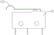
在上述所述的多功能试验箱中所述横向输送机构还包括两第一微动开关;In the above-mentioned multifunctional test box, the horizontal conveying mechanism also includes two first micro switches;

两所述第一微动开关分别沿所述第一滑轨的长度方向设于所述横向输送机构的同侧两端;The two first micro switches are respectively arranged at both ends of the same side of the transverse conveying mechanism along the length direction of the first slide rail;

所述第一滑块与所述微动开关同一侧设有第一触发件,用于触发所述第一微动开关;The first slider is provided with a first trigger on the same side as the micro switch, which is used to trigger the first micro switch;

两所述第一微动开关用于使所述升降机构停止相对于所述横向输送机构的运动,以使所述夹爪机构停止在所述第一放置位或所述第二放置位。The two first micro switches are used to stop the movement of the lifting mechanism relative to the transverse conveying mechanism, so that the gripper mechanism stops at the first placement position or the second placement position.

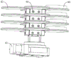
在上述所述的多功能试验箱中所述夹爪机构,包括:The jaw mechanism in the above-mentioned multifunctional test box includes:

电机、两夹持臂、第一连杆、第二连杆、导轨、第一安装件和第二安装件;A motor, two clamping arms, a first connecting rod, a second connecting rod, a guide rail, a first mounting part and a second mounting part;

两所述夹持臂分别具有工作端和连接端,两所述夹持臂的连接端分别固定于所述第一安装件和所述第二安装件;The two clamping arms respectively have working ends and connecting ends, and the connecting ends of the two clamping arms are respectively fixed to the first mounting part and the second mounting part;

所述第一安装件和所述第二安装件可活动地连接于所述导轨;The first mounting part and the second mounting part are movably connected to the guide rail;

所述第一安装件通过所述第一连杆连接于所述电机的转轴中心的一侧,所述第二安装件通过所述第二连杆连接于所述电机的转轴中心的另一侧;The first mounting part is connected to one side of the rotating shaft center of the motor through the first connecting rod, and the second mounting part is connected to the other side of the rotating shaft center of the motor through the second connecting rod ;

当所述电机正向转动时,所述第一连杆和所述第二连杆分别带动所述第一安装件和所述第二安装件沿所述导轨相向移动,以使两所述夹持臂夹紧培养皿;When the motor rotates in the forward direction, the first connecting rod and the second connecting rod respectively drive the first mounting part and the second mounting part to move toward each other along the guide rail, so that the two clips The holding arm clamps the petri dish;

当所述电机反向转动时,所述第一连杆和所述第二连杆分别带动所述第一安装件和所述第二安装件沿所述导轨朝相反方向移动,以使两所述夹持臂松开培养皿。When the motor rotates in the opposite direction, the first connecting rod and the second connecting rod respectively drive the first mounting part and the second mounting part to move in opposite directions along the guide rail, so that the two The gripping arm described above releases the Petri dish.

在上述所述的多功能试验箱中所述转轴与所述第一连杆和所述第二连杆连接的一端套设有电机安装件;In the above-mentioned multi-function test box, one end of the rotating shaft connected to the first connecting rod and the second connecting rod is sleeved with a motor mounting piece;

所述第一连杆和所述第二连杆分别可转动地连接于所述电机安装件且位于所述转轴的两侧。The first connecting rod and the second connecting rod are respectively rotatably connected to the motor mounting part and located on both sides of the rotating shaft.

在上述所述的多功能试验箱中,所述电机相邻两侧分别安装有一微动开关;In the above-mentioned multifunctional test box, a micro switch is respectively installed on the adjacent sides of the motor;

所述电机远离于所述第一连杆和所述第二连杆的一端安装有一限位杆;A limit rod is installed at one end of the motor away from the first connecting rod and the second connecting rod;

所述限位杆的一端连接于所述转轴,所述转轴在带动所述限位杆转动的过程中分别与两所述微动开关配合,以限制所述电机转轴的转动范围。One end of the limit rod is connected to the rotating shaft, and the rotating shaft cooperates with the two micro switches respectively during the process of driving the limit rod to rotate, so as to limit the rotation range of the motor rotating shaft.

在上述所述的多功能试验箱中,还包括安装于所述试验空间的温度调节机构,所述温度调节机构包括:In the multifunctional test box described above, it also includes a temperature adjustment mechanism installed in the test space, and the temperature adjustment mechanism includes:

电热管,所述电热管呈连续S状排列,适于安装于试验箱内的第一安装面,并沿所述第一安装面延伸;Electric heating tubes, the electric heating tubes are arranged in a continuous S shape, suitable for being installed on the first installation surface in the test chamber, and extending along the first installation surface;

支撑件,所述支撑件具有顶部支撑块和底部支撑块,所述顶部支撑块和所述底部支撑块夹紧所述电热管,所述底部支撑块适于固定在所述第一安装面,所述电热管悬空设置且所述电热管与所述第一安装面之间形成有空气层。a support, the support has a top support block and a bottom support block, the top support block and the bottom support block clamp the electric heating tube, and the bottom support block is suitable for being fixed on the first installation surface, The electric heating tube is suspended and an air layer is formed between the electric heating tube and the first installation surface.

在上述所述的多功能试验箱中,还包括连接杆,所述连接杆与多列呈S状排列的所述电热管交错连接设置。In the above-mentioned multifunctional test box, a connecting rod is further included, and the connecting rod is arranged in a staggered connection with a plurality of rows of the electric heating tubes arranged in an S shape.

在上述所述的多功能试验箱中,所述连接杆包括基杆和限位扣,所述限位扣固定于所述基杆,所述限位扣具有限位通道,所述电热管穿过所述限位通道。In the multifunctional test box described above, the connecting rod includes a base rod and a limit buckle, the limit buckle is fixed on the base rod, the limit buckle has a position-limiting channel, and the electric heating tube passes through through the limiting channel.

在上述所述的多功能试验箱中,所述限位扣是金属片,所述金属片的两端对折在中间部围绕形成所述限位通道,对折后的所述金属片的两端通过螺钉固定于所述基杆。In the above-mentioned multifunctional test box, the limit buckle is a metal sheet, and the two ends of the metal sheet are folded in half to form the limit passage in the middle, and the two ends of the folded metal sheet pass through Screws are fixed to the base rod.

与现有技术相比,本发明所提供的多功能试验箱具有以下至少一项有益效果:Compared with the prior art, the multifunctional test box provided by the present invention has at least one of the following beneficial effects:

1.本发明所提供的多功能试验箱,所述多功能试验箱的真空发生器能够在试验箱的试验空间内制造真空环境,以使得用于菌落计数的移动装置能够在真空环境下进行计数试验;1. The multifunctional test box provided by the present invention, the vacuum generator of the multifunctional test box can create a vacuum environment in the test space of the test box, so that the mobile device used for colony counting can count under the vacuum environment test;

2.本发明所提供的多功能试验箱,所述用于菌落计数的移动装置通过设置夹爪机构和拍照机构实现无须取出培养皿即可在培养箱内对培养皿中的菌落进行拍照和计数,避免工作人员将培养皿取出后影响培养皿中微生物的繁殖环境使研究结果产生偏差;2. In the multifunctional test box provided by the present invention, the mobile device for colony counting can take pictures and count the colonies in the culture dish in the incubator without taking out the culture dish by setting the gripper mechanism and the camera mechanism , to prevent the staff from taking out the petri dish and affecting the breeding environment of microorganisms in the petri dish, which will cause deviations in the research results;

3.本发明所提供的多功能试验箱,夹爪机构采用连杆将电机和两夹持臂连接在一起,代替齿轮传动,使得夹爪机构整体的重量变轻,响应更迅速,使用寿命更长。3. In the multifunctional test box provided by the present invention, the gripper mechanism uses connecting rods to connect the motor and the two gripper arms together instead of gear transmission, so that the overall weight of the gripper mechanism becomes lighter, the response is faster, and the service life is longer. long.

附图说明Description of drawings

下面将以明确易懂的方式,结合附图说明优选实施方式,对本发明的上述特性、技术特征、优点及其实现方式予以进一步说明。In the following, preferred embodiments will be described in a clear and understandable manner with reference to the accompanying drawings, and the above-mentioned characteristics, technical features, advantages and implementation methods of the present invention will be further described.

图1是本发明提供的用于菌落计数的移动装置的立体结构示意图;Fig. 1 is a three-dimensional structural schematic diagram of a mobile device for colony counting provided by the present invention;

图2是图1的爆炸视图;Figure 2 is an exploded view of Figure 1;

图3是本发明提供用于菌落计数的移动装置的正视图;Fig. 3 is the front view of the mobile device that the present invention provides for colony counting;

图4是本发明提供用于菌落计数的移动装置的俯视图Figure 4 is a top view of the mobile device used for colony counting provided by the present invention

图5是本发明提供的横向输送机构的立体结构示意图;Fig. 5 is a three-dimensional structural schematic diagram of the lateral conveying mechanism provided by the present invention;

图6是本发明提供的横向输送机构和升降机构的连接示意图;Fig. 6 is a schematic diagram of the connection of the horizontal conveying mechanism and the lifting mechanism provided by the present invention;

图7是本发明提供的夹爪机构的立体结构示意图;Fig. 7 is a three-dimensional schematic diagram of the jaw mechanism provided by the present invention;

图8是本发明提供的夹爪机构的内部结构示意图;Fig. 8 is a schematic diagram of the internal structure of the jaw mechanism provided by the present invention;

图9是本发明提供的横向输送机构、升降机构和夹爪机构的连接示意图;Fig. 9 is a schematic diagram of the connection of the horizontal conveying mechanism, the lifting mechanism and the gripper mechanism provided by the present invention;

图10是本发明提供的培养皿支架的立体结构示意图;Fig. 10 is a schematic diagram of the three-dimensional structure of the culture dish support provided by the present invention;

图11是本发明提供的培养皿支架在另一视角的结构示意图;Fig. 11 is a schematic structural view of the culture dish support provided by the present invention at another viewing angle;

图12是本发明提供的拍照机构的立体结构示意图;Fig. 12 is a three-dimensional structural schematic view of the camera mechanism provided by the present invention;

图13是本发明提供的微动开关的结构示意图;Fig. 13 is a structural schematic diagram of a micro switch provided by the present invention;

图14是本发明提供的升降机构支架22的结构示意图;Fig. 14 is a schematic structural view of the lifting mechanism bracket 22 provided by the present invention;

图15是本发明提供的夹爪机构的俯视图;Fig. 15 is a top view of the jaw mechanism provided by the present invention;

图16是图15中A-A处剖视图;Fig. 16 is a sectional view at A-A in Fig. 15;

图17是图16中B处的放大图;Figure 17 is an enlarged view at B in Figure 16;

图18是本发明提供的夹爪机构另一视角的立体结构示意图;Fig. 18 is a schematic perspective view of the three-dimensional structure of the jaw mechanism provided by the present invention from another perspective;

图19是本发明提供的夹爪机构的立体结构示意图;Fig. 19 is a schematic perspective view of the three-dimensional structure of the jaw mechanism provided by the present invention;

图20是本发明提供的夹爪机构的爆炸图;Fig. 20 is an exploded view of the jaw mechanism provided by the present invention;

图21是本发明提供的夹爪机构的内部结构示意图;Fig. 21 is a schematic diagram of the internal structure of the jaw mechanism provided by the present invention;

图22是本发明提供的夹爪机构在另一视角的结构示意图;Fig. 22 is a schematic structural view of the jaw mechanism provided by the present invention at another viewing angle;

图23是本发明提供的微动开关的结构示意图;Fig. 23 is a schematic structural diagram of a micro switch provided by the present invention;

图24是本发明提供的导轨的结构示意图;Fig. 24 is a schematic structural view of the guide rail provided by the present invention;

图25是本发明提供的滚珠连接件的结构示意图;Fig. 25 is a schematic structural view of the ball connector provided by the present invention;

图26是本发明提供的第一连接件的结构示意图;Fig. 26 is a schematic structural view of the first connector provided by the present invention;

图27是本发明提供的第二连接件的结构示意图;Fig. 27 is a schematic structural view of the second connector provided by the present invention;

图28是本发明提供的电机安装件的俯视图;Fig. 28 is a top view of the motor mount provided by the present invention;

图29是本发明提供的电机安装件的立体图;Fig. 29 is a perspective view of a motor mount provided by the present invention;

图30是本发明的优选实施例的温度调节机构的正面结构示意图;Fig. 30 is a schematic view of the front structure of the temperature adjustment mechanism of the preferred embodiment of the present invention;

图31是本发明的优选实施例的温度调节机构的侧面局部结构示意图;Fig. 31 is a schematic side view of the partial structure of the temperature adjustment mechanism of the preferred embodiment of the present invention;

图32是本发明的优选实施例的温度调节机构的支撑组件的结构示意图;Fig. 32 is a schematic structural view of a support assembly of a temperature adjustment mechanism in a preferred embodiment of the present invention;

图33是本发明的优选实施例的温度调节机构的限位扣的结构示意图;Fig. 33 is a schematic structural view of the limit buckle of the temperature adjustment mechanism of the preferred embodiment of the present invention;

图34是本发明的优选实施例的温度调节机构的限位扣的一变形实施方式的结构示意图;Fig. 34 is a structural schematic diagram of a modified embodiment of the limit buckle of the temperature adjustment mechanism of the preferred embodiment of the present invention;

图35是本发明的优选实施例的温度调节机构的制冷组件的结构示意图;Fig. 35 is a structural schematic diagram of the cooling assembly of the temperature adjustment mechanism of the preferred embodiment of the present invention;

图36是本发明的优选实施例的具有电化学测试功能的试验箱的立体结构示意图;Fig. 36 is a schematic perspective view of the three-dimensional structure of a test box with electrochemical testing functions in a preferred embodiment of the present invention;

图37是本发明的具有电化学测试功能的试验箱的正视结构示意图;Fig. 37 is the schematic diagram of the front view of the test box with electrochemical test function of the present invention;

图38是图36中A-A线剖视图;Figure 38 is a cross-sectional view of line A-A in Figure 36;

图39是图36中C-C线的剖视图;Figure 39 is a sectional view of line C-C in Figure 36;

图40是本发明的优选实施例的具有电化学测试功能的试验箱的电化学组件结构图;Fig. 40 is a structural diagram of electrochemical components of a test box with electrochemical testing function in a preferred embodiment of the present invention;

图41是图38中h处的局部放大图;Figure 41 is a partial enlarged view at h in Figure 38;

图42是本发明的优选实施例的试验箱的立体图。Fig. 42 is a perspective view of a test chamber of a preferred embodiment of the present invention.

附图标号说明:Explanation of reference numbers:

横向输送机构1,第一滑轨10,第一电机11,第一微动开关12,微动开关触头121,第一触发件13,第一滑块14,升降机构2,第二滑轨20,第二电机21,升降机构支架22,肋板221,连接板222,第二滑块23,第二触发件231,第二微动开关24,夹爪机构3,第三微动开关30,夹持臂31,工作端311,连接端312,第三电机32,驱动轴321,限位杆322,第一连杆33,第二连杆34,第一安装件35,第二安装件36,导轨37,壳体38,滑块391,圆弧形凹槽392,培养皿支架4,转轴41,托盘42,培养皿43,缓冲部44,支架电机45,螺丝46,拍照机构5,相机51,光源52,拍照机构支架53,试验箱主体100、真空发生器200,用于菌落计数的移动装置300;Transverse conveying mechanism 1, first slide rail 10, first motor 11, first micro switch 12, micro switch contact 121, first trigger 13, first slider 14, lifting mechanism 2, second slide rail 20, the second motor 21, the lifting mechanism bracket 22, the rib plate 221, the connecting plate 222, the second slider 23, the second trigger 231, the second micro switch 24, the jaw mechanism 3, the third micro switch 30 , clamping arm 31, working end 311, connecting end 312, third motor 32, drive shaft 321, limit rod 322, first connecting rod 33, second connecting rod 34, first mounting part 35, second mounting part 36, guide rail 37, housing 38, slider 391, arc-shaped groove 392, culture dish support 4, rotating shaft 41, tray 42, culture dish 43, buffer portion 44, bracket motor 45, screw 46, camera mechanism 5, Camera 51, light source 52, photographing mechanism support 53, test box main body 100, vacuum generator 200, mobile device 300 for colony counting;

壳体1a,上壳体11a,导轨111a,第一连杆1111a,第二连杆1112a,滑块112a,第一安装件1121a,第二安装件1122a,圆弧形凹槽1123a,滚珠连接件1124a,滚珠1125a,滚珠连接孔1126a,第一连接件113a,第一连接部1131a,第二连接件114a,第二连接部1141a,下壳体12a,夹持口121a,夹持臂2a,工作端21a,连接端22a,电机3a,电机安装件31a,第一连接孔311a,转轴连接孔312a,限位孔313a,转轴32a,限位杆33a,微动开关34a,微动开关触头341a,培养皿4a;Housing 1a, upper housing 11a, guide rail 111a, first connecting rod 1111a, second connecting rod 1112a, slider 112a, first mounting part 1121a, second mounting part 1122a, arc-shaped groove 1123a, ball joint 1124a, ball 1125a, ball connecting hole 1126a, first connecting piece 113a, first connecting portion 1131a, second connecting piece 114a, second connecting portion 1141a, lower housing 12a, clamping port 121a, clamping arm 2a, working End 21a, connecting end 22a, motor 3a, motor mount 31a, first connecting hole 311a, rotating shaft connecting hole 312a, limit hole 313a, rotating shaft 32a, limit rod 33a, micro switch 34a, micro switch contact 341a , Petri dish 4a;

电热管200b,支撑组件300b,顶部支撑块301b,底部支撑块302b,试验箱100b,第一安装面101b,连接杆400b,基杆401b,限位扣402b,限位通道4020b,金属片4021b,螺钉403b,制冷组件500b,导流管501b,进液箱502b,回收箱503b,测温元件600b,安装孔700b;Electric heating tube 200b, support assembly 300b, top support block 301b, bottom support block 302b, test box 100b, first installation surface 101b, connecting rod 400b, base rod 401b, limit buckle 402b, limit channel 4020b, metal sheet 4021b, Screw 403b, refrigeration assembly 500b, guide tube 501b, liquid inlet tank 502b, recovery tank 503b, temperature measuring element 600b, installation hole 700b;

箱体1c,工作窗口101c,密封磁条102c,电化学工作站2c,抽气泵3c,气管301c,连接头302c,开关盒4c,封板5c,把手501c,检测板6c,真空计601c,温度计602c,照明灯7c,加热安装架8c,金属加热环9c,放置台10c,定位板11c,托盘111c,电解液容纳盒12c,盖板121c,定位套筒13c,测试探针131c,金属夹头14c,电连接线15c,密封插电接头16c,玻璃罩筒17c,步进电机18c,安装座181c,LED灯191c,氙灯192c,汞灯193c,转接罩壳20c,电动缸21c,密封堵块211c。Box 1c, working window 101c, sealing magnetic strip 102c, electrochemical workstation 2c, air pump 3c, gas pipe 301c, connector 302c, switch box 4c, sealing plate 5c, handle 501c, detection board 6c, vacuum gauge 601c, thermometer 602c , lighting lamp 7c, heating installation frame 8c, metal heating ring 9c, placing table 10c, positioning plate 11c, tray 111c, electrolyte containing box 12c, cover plate 121c, positioning sleeve 13c, test probe 131c, metal chuck 14c , electrical connecting wire 15c, sealed plug connector 16c, glass cover tube 17c, stepper motor 18c, mounting base 181c, LED lamp 191c, xenon lamp 192c, mercury lamp 193c, adapter cover 20c, electric cylinder 21c, sealing block 211c.

具体实施方式Detailed ways

为了更清楚地说明本发明实施例或现有技术中的技术方案,下面将对照附图说明本发明的具体实施方式。显而易见地,下面描述中的附图仅仅是本发明的一些实施例,对于本领域普通技术人员来讲,在不付出创造性劳动的前提下,还可以根据这些附图获得其他的附图,并获得其他的实施方式。In order to more clearly illustrate the embodiments of the present invention or the technical solutions in the prior art, the specific implementation manners of the present invention will be described below with reference to the accompanying drawings. Obviously, the accompanying drawings in the following description are only some embodiments of the present invention, and those skilled in the art can obtain other accompanying drawings based on these drawings and obtain other implementations.

为使图面简洁,各图中只示意性地表示出了与发明相关的部分,它们并不代表其作为产品的实际结构。另外,以使图面简洁便于理解,在有些图中具有相同结构或功能的部件,仅示意性地绘示了其中的一个,或仅标出了其中的一个。在本文中,“一个”不仅表示“仅此一个”,也可以表示“多于一个”的情形。In order to keep the drawings concise, each drawing only schematically shows the parts related to the invention, and they do not represent the actual structure of the product. In addition, to make the drawings concise and easy to understand, in some drawings, only one of the components having the same structure or function is schematically shown, or only one of them is marked. Herein, "a" not only means "only one", but also means "more than one".

还应当进一步理解,在本申请说明书和所附权利要求书中使用的术语“和/或”是指相关联列出的项中的一个或多个的任何组合以及所有可能组合,并且包括这些组合。It should also be further understood that the term "and/or" used in the description of the present application and the appended claims refers to any combination and all possible combinations of one or more of the associated listed items, and includes these combinations .

在本文中,需要说明的是,除非另有明确的规定和限定,术语“安装”、“相连”、“连接”应做广义理解,例如,可以是固定连接,也可以是可拆卸连接,或一体地连接;可以是机械连接,也可以是电连接;可以是直接相连,也可以通过中间媒介间接相连,可以是两个元件内部的连通。对于本领域的普通技术人员而言,可以具体情况理解上述术语在本发明中的具体含义。In this article, it needs to be explained that unless otherwise clearly specified and limited, the terms "installation", "connection" and "connection" should be understood in a broad sense, for example, it can be a fixed connection or a detachable connection, or Integral connection; it can be mechanical connection or electrical connection; it can be direct connection or indirect connection through an intermediary, and it can be the internal communication of two components. Those of ordinary skill in the art can understand the specific meanings of the above terms in the present invention in specific situations.

另外,在本申请的描述中,术语“第一”、“第二”等仅用于区分描述,而不能理解为指示或暗示相对重要性。In addition, in the description of the present application, the terms "first", "second" and the like are only used to distinguish descriptions, and cannot be understood as indicating or implying relative importance.

实施例1Example 1

参考图1至图,本申请所提供的多功能试验箱包括试验箱主体100、真空发生器200以及用于菌落计数的移动装置300,所述试验箱主体100具有试验空间,所述用于菌落计数的移动装置300安装于所述试验空间,所述真空发生器200安装于所述试验箱主体100,用于抽出所述试验空间中的空气以在所述试验空间内制造真空。With reference to Fig. 1 to figure, the multifunctional test box provided by the present application comprises test box main body 100, vacuum generator 200 and the moving device 300 that is used for colony counting, and described test box main body 100 has test space, and described test box main body 100 has test space, and described test box main body 100 is used for colony counting. The counting moving device 300 is installed in the test space, and the vacuum generator 200 is installed in the test box main body 100 for extracting air in the test space to create a vacuum in the test space.

本申请所提供的所述多功能试验箱既能够进行微生物的培养与检测,也能够用于微生物的腐蚀测试,所述多功能试验箱还能够用于其他的与微生物实验相关的试验,具体的试验类型不应当构成对本申请的限制。The multifunctional test box provided in this application can not only be used for the cultivation and detection of microorganisms, but also can be used for the corrosion test of microorganisms. The multifunctional test box can also be used for other tests related to microbial experiments, specifically The type of test should not constitute a limitation of the application.

参考说明书附图1至图13,所提供的用于菌落计数的移动装置具体包括横向输送机构1、升降机构2、夹爪机构3、培养皿支架4和拍照机构5。其中培养皿支架4具有第一放置位,用于放置培养皿43。拍照机构5具有第二放置位,用于对第二放置位中的培养皿43进行拍照计数。而横向输送机构1设置于培养皿支架4的一侧。升降机构2可滑动地连接于横向输送机构1,夹爪机构3可滑动地连接于升降机构2。通过横向输送机构1和升降机构2的配合,可使夹爪机构3沿X轴和Z轴方向并在第一放置位和第二放置位之间运动,极大地减小了夹爪机构3的运动范围,节省了培养箱内的空间。Referring to accompanying drawings 1 to 13 of the specification, the provided mobile device for colony counting specifically includes a lateral conveying mechanism 1 , a lifting mechanism 2 , a gripper mechanism 3 , a petri dish support 4 and a photographing mechanism 5 . Wherein the petri dish support 4 has a first placement position for placing a petri dish 43 . The photographing mechanism 5 has a second placement position for photographing and counting the petri dishes 43 in the second placement position. And the lateral conveying mechanism 1 is arranged on one side of the culture dish support 4 . The lifting mechanism 2 is slidably connected to the horizontal conveying mechanism 1 , and the gripper mechanism 3 is slidably connected to the lifting mechanism 2 . Through the cooperation of the horizontal conveying mechanism 1 and the lifting mechanism 2, the jaw mechanism 3 can be moved along the X-axis and the Z-axis direction and between the first placement position and the second placement position, which greatly reduces the stress of the gripper mechanism 3. range of motion and saves space inside the incubator.

参考图5,具体地,在本实施例中,横向输送机构1包括第一滑轨10、第一滑块14和第一电机11。本实施例中,第一滑轨10位于横向输送机构1的上表面,第一滑块14可滑动地连接于第一滑轨10,显然,第一滑块14的底部形状配合于第一滑轨10以使第一滑块14可相对于横向输送机构1沿第一滑轨10移动。进一步地,第一滑块14用以连接升降机构2,且连接后第一滑块14和升降机构2同步沿移动,以使升降机构2随第一滑块14相对于横向输送机构1移动。第一电机11设于横向输送机构1的一端,用于驱动第一滑块14沿第一滑轨10滑动;可选地,参考图6和图14,在第一滑块14上可安装升降机构支架22,用于支撑升降机构2,提高横向输送机构1和升降机构2的连接以及相对移动时的稳定性。优选地,升降机构支架22包括两肋板221以及一连接板222,支撑并连接升降机构2。两肋板221分别固定于连接板222同一侧的两端,当然,两肋板221和连接板222也可以是一体成型的。只要其能够起到加强连接稳定性以及支撑的作用即可。从图14中可以清楚看到,本实施例中连接板222的表面设有多个大小不一的螺丝孔,螺丝孔用于将升降机构2与连接板222固定。参考图6,横向输送机构1工作时,第一滑块14沿第一滑轨10移动,同时带动升降机构支架22以及升降机构2同步移动。Referring to FIG. 5 , specifically, in this embodiment, the transverse conveying mechanism 1 includes a first slide rail 10 , a first slider 14 and a first motor 11 . In this embodiment, the first slide rail 10 is located on the upper surface of the transverse conveying mechanism 1, and the first slide block 14 is slidably connected to the first slide rail 10. Obviously, the shape of the bottom of the first slide block 14 is matched with the first slide rail. The rail 10 enables the first sliding block 14 to move along the first sliding rail 10 relative to the transverse conveying mechanism 1 . Further, the first slider 14 is used to connect the lifting mechanism 2 , and after the connection, the first slider 14 and the lifting mechanism 2 move synchronously, so that the lifting mechanism 2 moves with the first slider 14 relative to the transverse conveying mechanism 1 . The first motor 11 is arranged at one end of the transverse conveying mechanism 1, and is used to drive the first slide block 14 to slide along the first slide rail 10; The mechanism bracket 22 is used to support the lifting mechanism 2, and improve the connection between the horizontal conveying mechanism 1 and the lifting mechanism 2 and the stability during relative movement. Preferably, the lifting mechanism bracket 22 includes two ribs 221 and a connecting plate 222 to support and connect the lifting mechanism 2 . The two ribs 221 are respectively fixed to the two ends of the same side of the connecting plate 222 , of course, the two ribs 221 and the connecting plate 222 may also be integrally formed. As long as it can play the role of strengthening the connection stability and support. It can be clearly seen from FIG. 14 that the surface of the connecting plate 222 in this embodiment is provided with a plurality of screw holes of different sizes, and the screw holes are used to fix the lifting mechanism 2 and the connecting plate 222 . Referring to FIG. 6 , when the transverse conveying mechanism 1 is working, the first slider 14 moves along the first slide rail 10 , and at the same time drives the lifting mechanism bracket 22 and the lifting mechanism 2 to move synchronously.

进一步地,参考图5,第一滑块14的侧面向下延伸设有第一触发件13,同时在横向输送机构1侧面沿第一滑轨10的方向分别设有两第一微动开关12,具体地,微动开关的具体结构参考图13,包括微动开关本体和微动开关触头121,微动开关本体与系统相连,当第一滑块14移动到与第一微动开关12对应的位置时,第一触发件13触碰到微动开关触头121,第一微动开关12向系统发送指令使横向输送机构1停止工作即停止第一滑块14相对于第一滑轨10的移动,其作用在于使升降机构2停止相对于横向输送机构1的运动,以使夹爪机构3停止在第一放置位或第二放置位。Further, referring to FIG. 5 , the side of the first slide block 14 is extended downward with a first trigger member 13 , and at the same time, two first microswitches 12 are respectively provided on the side of the lateral conveying mechanism 1 along the direction of the first slide rail 10 Specifically, the specific structure of the micro switch refers to FIG. 13 , including the micro switch body and the micro switch contact 121. The micro switch body is connected with the system. At the corresponding position, the first trigger member 13 touches the microswitch contact 121, and the first microswitch 12 sends an instruction to the system to stop the transverse conveying mechanism 1, that is, stop the first slider 14 from moving relative to the first slide rail. The movement of 10 is to stop the lifting mechanism 2 from moving relative to the transverse conveying mechanism 1, so that the jaw mechanism 3 stops at the first placement position or the second placement position.

需要特别指出的是,前述设于横向输送机构1的第一微动开关12可以替换为其他部件如传感器等。优选地,在横向输送机构1的第一滑轨10的两端分别设有一第一传感器,其通过检测升降机构2相对于横向输送机构1的位置以使夹爪机构3停止第一放置位或第二放置位。具体而言,在第一滑轨10沿滑轨方向的两端分别设有一第一传感器,当第一滑块14移动到第一传感器的位置时,第一传感器向系统反馈,由系统控制横向输送机构1停止工作。It should be pointed out that the aforementioned first microswitch 12 provided on the transverse conveying mechanism 1 can be replaced by other components such as sensors and the like. Preferably, a first sensor is respectively provided at both ends of the first slide rail 10 of the transverse conveying mechanism 1, which detects the position of the lifting mechanism 2 relative to the transverse conveying mechanism 1 so that the gripper mechanism 3 stops at the first placement position or Second placement. Specifically, a first sensor is respectively provided at both ends of the first slide rail 10 along the direction of the slide rail. When the first slider 14 moves to the position of the first sensor, the first sensor feeds back to the system, and the system controls the horizontal direction. Conveying mechanism 1 stops working.

对于第一传感器的类型,本发明不做具体限制,其可以是光电传感器,也可以是位移传感器或者其他类型的传感器,只要其能够实现上述功能即可,在此不过多赘述。The present invention does not specifically limit the type of the first sensor, which may be a photoelectric sensor, a displacement sensor or other types of sensors, as long as it can realize the above functions, and will not be described in detail here.

参考图6和图9,升降机构2包括第二滑轨20、第二滑块23和第二电机21。第二滑块23可滑动地连接于第二滑轨20。第二电机21设于升降机构2的一端,用于驱动第二滑块23沿第二滑轨20滑动。夹爪机构3固定于第二滑块23。升降机构2的一侧安装于横向输送机构1,另一侧为第二滑轨20。具体地,在上述实施例的基础上,升降机构2通过螺丝安装于升降机构支架22的连接板222上,并随第一滑块14沿第一滑轨10移动。需要指出的是,上述连接方式只是本发明所提供的一种实施例,可选地,升降机构2也可通过其他方式或直接安装于第一滑块14,其不应当构成对本发明的限制。Referring to FIG. 6 and FIG. 9 , the lifting mechanism 2 includes a second slide rail 20 , a second slider 23 and a second motor 21 . The second sliding block 23 is slidably connected to the second sliding rail 20 . The second motor 21 is disposed at one end of the lifting mechanism 2 for driving the second slider 23 to slide along the second slide rail 20 . The jaw mechanism 3 is fixed on the second slider 23 . One side of the lifting mechanism 2 is installed on the transverse conveying mechanism 1 , and the other side is the second slide rail 20 . Specifically, on the basis of the above embodiments, the lifting mechanism 2 is mounted on the connecting plate 222 of the lifting mechanism bracket 22 through screws, and moves along the first sliding rail 10 with the first sliding block 14 . It should be pointed out that the above connection method is only an embodiment provided by the present invention. Optionally, the lifting mechanism 2 can also be installed on the first slider 14 in other ways or directly, which should not limit the present invention.

进一步地,第二滑块23用于连接夹爪机构3,以带动夹爪机构3实现X轴和Y轴方向上的移动,使其能够将培养皿43夹持至拍照机构5。并且第二滑块23上设有若干螺丝孔,用于连接夹爪机构3。Further, the second slider 23 is used to connect the gripper mechanism 3 to drive the gripper mechanism 3 to move in the X-axis and Y-axis directions, so that it can grip the culture dish 43 to the camera mechanism 5 . And the second slide block 23 is provided with several screw holes for connecting the jaw mechanism 3 .

参考图6,在升降机构2相对于第二滑轨20的侧面装有两第二微动开关24,且第二滑块23的侧面延伸形成与第二微动开关24配合的第二触发件231,当第二滑块23移动到与第二微动开关24对应的位置时,第二触发件231将会触碰到微动开关触头121,第二微动开关24向系统发送指令使升降机构1停止工作,其作用在于使第二滑块23停止在第一放置位或者第二放置位。需要特别指出的是,前述升降机构2的第二微动开关24可以替换为其他部件如传感器等。优选地,在升降机构2的第二滑轨20的两端分别设有一第二传感器,其通过检测夹爪机构3相对于升降机构2的位置以使夹爪机构3停止在第一放置位或第二放置位。具体而言,在第二滑轨20沿滑轨方向的两端分别设有一第二传感器,当第一滑块23移动到第二传感器的位置时,第二传感器向系统反馈,由系统控制升降机构2停止工作。Referring to FIG. 6 , two second microswitches 24 are installed on the side of the lifting mechanism 2 relative to the second slide rail 20 , and the side of the second slider 23 extends to form a second trigger that cooperates with the second microswitch 24 231, when the second slider 23 moves to the position corresponding to the second micro switch 24, the second trigger 231 will touch the micro switch contact 121, and the second micro switch 24 sends an instruction to the system to make The lifting mechanism 1 stops working, and its function is to stop the second slider 23 at the first placement position or the second placement position. It should be pointed out that the second microswitch 24 of the lifting mechanism 2 can be replaced by other components such as sensors. Preferably, a second sensor is respectively provided at both ends of the second slide rail 20 of the lifting mechanism 2, which detects the position of the jaw mechanism 3 relative to the lifting mechanism 2 so that the jaw mechanism 3 stops at the first placement position or Second placement. Specifically, a second sensor is respectively provided at both ends of the second slide rail 20 along the direction of the slide rail. When the first slider 23 moves to the position of the second sensor, the second sensor feeds back to the system, and the system controls the lifting Agency 2 stopped working.

对于第二传感器的类型,本发明不做具体限制,其可以是光电传感器,也可以是位移传感器或者其他类型的传感器,只要其能够实现上述功能即可,在此不过多赘述。The present invention does not specifically limit the type of the second sensor, which may be a photoelectric sensor, a displacement sensor or other types of sensors, as long as it can realize the above functions, and will not be repeated here.

如前所述,横向输送机构1与升降机构2配合用于带动夹爪机构3将培养皿43从第一放置位夹持至第二放置位即从培养皿支架4夹持至拍照机构5进行拍照,然后将照片上传至系统对培养皿43内的菌落进行计数。整个过程中无需工作人员将培养皿43从培养箱中取出,可有效地避免因培养皿短暂离开培养箱而导致研究结果出现偏差,保证了研究实验的准确性。As mentioned above, the horizontal conveying mechanism 1 and the lifting mechanism 2 are used to drive the gripper mechanism 3 to clamp the culture dish 43 from the first placement position to the second placement position, that is, from the culture dish support 4 to the camera mechanism 5. Take pictures, and then upload the pictures to the system to count the colonies in the petri dish 43 . During the whole process, there is no need for staff to take out the petri dish 43 from the incubator, which can effectively avoid the deviation of the research results caused by the petri dish leaving the incubator for a short time, and ensure the accuracy of the research experiment.

在一个实施例中,参考图1和图12,拍照机构5包括相机51、光源52和拍照机构支架53,相机51与光源52分别连接于拍照机构支架53的上下两端,具体地,相机51位于光源52的上方,拍照时,培养皿43位于相机51和光源52之间。由于培养箱中的环境相对较暗,直接拍照会由于亮度的原因导致照片不清晰,进而对菌落计数出现偏差影响实验结果,因此设置光源52对培养皿43进行补光,以避免上述情况导致的结果偏差。In one embodiment, with reference to Fig. 1 and Fig. 12, the photographing mechanism 5 comprises a camera 51, a light source 52 and a photographing mechanism bracket 53, the camera 51 and the light source 52 are respectively connected to the upper and lower ends of the photographing mechanism bracket 53, specifically, the camera 51 Located above the light source 52 , the petri dish 43 is located between the camera 51 and the light source 52 when taking pictures. Because the environment in the incubator is relatively dark, taking pictures directly will cause the photos to be unclear due to the brightness, and then affect the experimental results due to the deviation of the colony count. The results are biased.

在一个实施例中,参考图1和图7-9,本发明所提供的用于菌落计数的移动装置中的夹爪机构3具体包括了壳体38、第三电机32、两夹持臂31和连接组件。其中第三电机32安装于壳体38。连接组件安装于壳体38的内部且连接于第三电机32。两夹持臂31分别具有工作端311和连接端312,两夹持臂31的工作端311用于夹持培养皿43,两夹持臂31的连接端312分别固定于连接组件。第三电机32通过驱动连接组件以控制两夹持臂31夹紧或松开以夹持或放下培养皿43。In one embodiment, referring to Fig. 1 and Fig. 7-9, the gripper mechanism 3 in the mobile device for colony counting provided by the present invention specifically includes a housing 38, a third motor 32, and two gripping arms 31 and connected components. Wherein the third motor 32 is mounted on the casing 38 . The connection assembly is mounted inside the housing 38 and connected to the third motor 32 . The two clamping arms 31 respectively have a working end 311 and a connecting end 312 , the working ends 311 of the two clamping arms 31 are used to clamp the culture dish 43 , and the connecting ends 312 of the two clamping arms 31 are respectively fixed to the connection assembly. The third motor 32 drives the connection assembly to control the clamping or loosening of the two clamping arms 31 to clamp or put down the culture dish 43 .

进一步地,连接组件包括第一连杆33、第二连杆34、导轨37、第一安装件35和第二安装件36。导轨37安装于壳体38,第一安装件35和第二安装件36可活动地连接于导轨37。两夹持臂31的连接端312分别连接于第一安装件35和第二安装件36。第一安装件35通过第一连杆33连接于第三电机32转轴中心的一侧,第二安装件36通过第二连杆34连接于第三电机32转轴中心的另一侧。Further, the connecting assembly includes a first connecting rod 33 , a second connecting rod 34 , a guide rail 37 , a first mounting part 35 and a second mounting part 36 . The guide rail 37 is mounted on the housing 38 , and the first mounting part 35 and the second mounting part 36 are movably connected to the guide rail 37 . The connecting ends 312 of the two clamping arms 31 are respectively connected to the first mounting part 35 and the second mounting part 36 . The first mounting part 35 is connected to one side of the rotation axis center of the third motor 32 through the first connecting rod 33 , and the second mounting part 36 is connected to the other side of the rotation shaft center of the third motor 32 through the second connecting rod 34 .

其工作原理如下:It works as follows:

当第三电机32正向转动时,第一连杆33和第二连杆34分别带动第一安装件35和第二安装件36沿导轨37相向移动,以使两夹持臂31夹紧。When the third motor 32 rotates in the forward direction, the first connecting rod 33 and the second connecting rod 34 respectively drive the first mounting part 35 and the second mounting part 36 to move toward each other along the guide rail 37 so that the two clamping arms 31 are clamped.

当第三电机32反向转动时,第一连杆33和第二连杆34分别带动第一安装件35和第二安装件36沿导轨37朝相反方向移动,以使两夹持臂31松开。When the third motor 32 reversely rotates, the first connecting rod 33 and the second connecting rod 34 respectively drive the first mounting part 35 and the second mounting part 36 to move in opposite directions along the guide rail 37, so that the two clamping arms 31 are loosened. open.

可选地,参考图17,第一安装件35和第二安装件36分别通过滑块391与导轨37连接,且滑块391与导轨37通过若干滚珠配合以使夹持臂31的夹紧和松开的动作更为顺滑,相应地,导轨37与滑块391配合的两侧以及滑块391与导轨37配合的两侧均设有配合于滚珠的圆弧形凹槽392。Optionally, referring to FIG. 17 , the first mounting part 35 and the second mounting part 36 are respectively connected to the guide rail 37 through a slide block 391, and the slide block 391 and the guide rail 37 cooperate with each other through several balls to make the clamping and clamping of the clamping arm 31 possible. The loosening action is smoother. Correspondingly, the two sides where the guide rail 37 cooperates with the slide block 391 and the two sides where the slide block 391 cooperates with the guide rail 37 are provided with arc-shaped grooves 392 that are matched with the balls.

参考图18,本实施例中,电机32的相邻两侧面分别安装有一个第三微动开关30,相应地,在电机32的顶部,有一限位杆322连接于电机32的驱动轴321,且限位杆322与驱动轴321同步转动,当然地,限位杆322在转动过程中可以触碰到两第三微动开关30的微动开关触头121,设于电机32的两第三微动开关30用于限制电机32的驱动轴321的转动,以避免驱动轴过度转动导致第一连杆33和第二连杆34这段致使夹爪机构3损坏,避免造成经济损失和对实验造成影响。其原理为,设置在电机32相邻两侧的第三微动开关30共同构成了对驱动轴321转动范围的限制,其目的是限制俩夹持臂31沿导轨37的移动范围,避免驱动轴过度转动导致第一连杆33和第二连杆34的损坏。当限位杆322随驱动轴321的转动而触碰到微动开关触头121时,第三微动开关30向系统反馈,由系统控制驱动轴321停止转动,进而两夹持臂31停止移动。Referring to FIG. 18 , in this embodiment, a third microswitch 30 is respectively installed on the adjacent two sides of the motor 32 , and correspondingly, on the top of the motor 32 , there is a limit rod 322 connected to the drive shaft 321 of the motor 32 , And the limit rod 322 rotates synchronously with the drive shaft 321. Of course, the limit rod 322 can touch the micro switch contacts 121 of the two third micro switches 30 during the rotation process, which are arranged on the two third micro switches 30 of the motor 32. The microswitch 30 is used to limit the rotation of the drive shaft 321 of the motor 32, so as to avoid the excessive rotation of the drive shaft from causing damage to the jaw mechanism 3 in the section of the first connecting rod 33 and the second connecting rod 34, thereby avoiding economic loss and damage to the experiment. make an impact. The principle is that the third microswitches 30 arranged on the adjacent two sides of the motor 32 jointly constitute a limit to the rotation range of the drive shaft 321, the purpose of which is to limit the range of movement of the two clamping arms 31 along the guide rail 37, so as to prevent the drive shaft from Excessive rotation results in damage to the first link 33 and the second link 34 . When the limit rod 322 touches the micro switch contact 121 with the rotation of the drive shaft 321, the third micro switch 30 feeds back to the system, and the system controls the drive shaft 321 to stop rotating, and then the two clamping arms 31 stop moving .

进一步地,夹爪机构3设有第二传感器,用以检测两夹持臂31之间的距离,以确认两夹持臂31将培养皿43夹紧后再开始移动,放置培养皿43从两夹持臂31中滑落造成经济损失以及影响实验进行。参考图3,可选地,第二传感器可以设置在电机32的转轴处,检测第一连杆33和第二连杆34相对于电机32转轴的位置,进而检测两夹持臂31之间的距离。可选地,第二传感器可以设置于导轨37,用以检测第一安装件35和第二安装件36之间的距离,进而检测两夹持臂31之间的距离。可选地,第二传感器可以设置在两夹持臂31的连接端312,用以检测两夹持臂31之间的距离。可选地,第二传感器可设置在两夹持臂31与培养皿43接触的一侧,以直接检测两夹持臂31与培养皿43之间的夹持情况。需要进一步指出的是,对于第二传感器的类型不做具体限制,其可以是光电传感器,也可以是位移传感器、压力传感器或者其他类型的传感器,只要其能够实现上述功能即可,在此不过多赘述。Further, the jaw mechanism 3 is provided with a second sensor for detecting the distance between the two clamping arms 31, so as to confirm that the two clamping arms 31 clamp the petri dish 43 before starting to move, and place the petri dish 43 from the two sides. Slippage in the clamping arm 31 causes economic loss and affects the performance of experiments. Referring to Fig. 3, optionally, the second sensor may be arranged at the rotating shaft of the motor 32 to detect the positions of the first connecting rod 33 and the second connecting rod 34 relative to the rotating shaft of the motor 32, and then detect the position between the two clamping arms 31. distance. Optionally, the second sensor can be arranged on the guide rail 37 to detect the distance between the first mounting part 35 and the second mounting part 36 , and then detect the distance between the two clamping arms 31 . Optionally, the second sensor can be arranged at the connecting end 312 of the two clamping arms 31 to detect the distance between the two clamping arms 31 . Optionally, the second sensor can be arranged on the side where the two clamping arms 31 are in contact with the culture dish 43 , so as to directly detect the clamping situation between the two clamping arms 31 and the culture dish 43 . It should be further pointed out that there is no specific limitation on the type of the second sensor, which can be a photoelectric sensor, a displacement sensor, a pressure sensor or other types of sensors, as long as it can realize the above functions, and there are no more details here. repeat.

在一些优选实施方式中,两夹持臂31与培养皿43接触的一面设有用以防止培养皿43滑落的防滑部。对于防滑部的具体类型,本发明不做具体限制,其可以是增大摩擦力的凸点,也可以是防滑槽等,优选的实施方案为在两夹持臂31上套设橡胶或者在两夹持臂31与培养皿接触的一面贴上橡胶层。In some preferred embodiments, the sides of the two clamping arms 31 that are in contact with the culture dish 43 are provided with anti-slip parts for preventing the culture dish 43 from slipping. For the specific type of the anti-slip part, the present invention does not specifically limit it, it can be a bump that increases the frictional force, or an anti-skid groove, etc. The preferred embodiment is to sleeve rubber on the two clamping arms 31 or to cover the two clamping arms 31. The side of the clamping arm 31 in contact with the culture dish is pasted with a rubber layer.

在一个实施例中,参考图1、图10和图11,本发明所提供的用于菌落计数的移动装置中的培养皿支架4包括转轴41和若干托盘42。其中,托盘43用于放置培养皿43,具体而言,托盘42连接于转轴41。转轴41可带动托盘42旋转。其中,托盘42与转轴41通过螺丝连接,参考图10,托盘42的一端设有凸块,凸块上开设有螺丝孔,相应地,转轴41与托盘42连接处设有凸块,凸块上开设螺丝孔,安装时,托盘42和转轴41的凸块上下叠放且螺丝孔相对,通过螺丝将托盘42和转轴41固定。本实施例中,凸块上优选地设有两个螺丝孔,以加强托盘42和转轴41的连接稳定性。In one embodiment, referring to FIG. 1 , FIG. 10 and FIG. 11 , the petri dish support 4 in the mobile device for colony counting provided by the present invention includes a rotating shaft 41 and several trays 42 . Wherein, the tray 43 is used to place the culture dish 43 , specifically, the tray 42 is connected to the rotating shaft 41 . The rotating shaft 41 can drive the tray 42 to rotate. Wherein, the tray 42 and the rotating shaft 41 are connected by screws. Referring to FIG. 10 , one end of the tray 42 is provided with a protrusion, and a screw hole is provided on the protrusion. Provide screw holes, during installation, the protrusions of the tray 42 and the rotating shaft 41 are stacked up and down and the screw holes are opposite, and the tray 42 and the rotating shaft 41 are fixed by screws. In this embodiment, two screw holes are preferably provided on the protrusion to enhance the stability of the connection between the tray 42 and the rotating shaft 41 .

进一步地,培养皿支架4设有若干组托盘42,且每组托盘42呈间隔相等地沿转轴41的轴向设置,以此极大地提升培养皿支架4的容量。优选地,若干组托盘42呈间隔相等地环设于转轴41。Further, the culture dish support 4 is provided with several groups of trays 42 , and each group of trays 42 is arranged at equal intervals along the axial direction of the rotating shaft 41 , thereby greatly increasing the capacity of the culture dish support 4 . Preferably, several groups of trays 42 are arranged around the rotating shaft 41 at equal intervals.

当需要对培养皿43拍照时,控制夹爪机构3夹持培养皿43至拍照机构5进行拍照,拍照结束后控制夹爪机构3将培养皿43放回托盘42,接着控制转轴41转动,将下一个待拍照的培养皿43转动至夹爪机构3可夹持的位置以供夹爪机构3将其夹持至拍照机构5。When the petri dish 43 needs to be photographed, the gripper mechanism 3 is controlled to clamp the petri dish 43 to the photographing mechanism 5 to take pictures. After the photograph is completed, the gripper mechanism 3 is controlled to put the petri dish 43 back into the tray 42, and then the rotating shaft 41 is controlled to rotate, and the The next petri dish 43 to be photographed is rotated to a clampable position of the clamping mechanism 3 so that the clamping mechanism 3 can clamp it to the photographing mechanism 5 .

可选地,在转轴41与培养皿43相对的一面设有缓冲部44,缓冲部44的作用在于,当夹爪机构3将培养皿43放回托盘42时,防止托盘42撞击转轴41造成培养皿破碎,导致经济损失且影响实验的进行。进一步地,缓冲部44可以是两个橡胶块,分别设置在托盘42与转轴41连接处的上方,当夹持机构3将培养皿43放回托盘42时,两个橡胶块抵接于培养皿43防止其撞击转轴41导致培养皿43损坏。当然,缓冲部44也可以是一个大的橡胶块,或者海绵块等,其数量、形状、材质均不受限制,只要其能够达到上述效果即可。Optionally, a buffer portion 44 is provided on the opposite side of the rotating shaft 41 to the culture dish 43. The function of the buffer portion 44 is to prevent the tray 42 from colliding with the rotating shaft 41 when the jaw mechanism 3 puts the culture dish 43 back into the tray 42 to cause the culture Dishes are broken, resulting in economic losses and affecting the progress of the experiment. Further, the buffer part 44 can be two rubber blocks, which are respectively arranged above the connection between the tray 42 and the rotating shaft 41. When the clamping mechanism 3 puts the culture dish 43 back into the tray 42, the two rubber blocks abut against the culture dish. 43 prevents it from hitting the rotating shaft 41 and causing the culture dish 43 to be damaged. Of course, the buffer portion 44 can also be a large rubber block, or a sponge block, etc., and its quantity, shape, and material are not limited, as long as it can achieve the above effects.

还需要指出的是,本申请所提供的所述试验空间中还安装有气体传感器,用于检测所述试验空间中的气体成分。所述多功能试验箱还包括安装于所述试验空间外侧的控制单元以及电脑操作系统,用于实时显示所述试验空间中的状态参数。It should also be pointed out that a gas sensor is installed in the test space provided in the present application to detect the gas components in the test space. The multifunctional test box also includes a control unit and a computer operating system installed outside the test space for real-time display of state parameters in the test space.

实施例2Example 2

参考说明书附图19至图27,夹爪机构包括壳体1a,电机3a、两夹持臂2a、第一连杆1111a、第二连杆1112a、导轨111a、第一安装件1121a和第二安装件1122a。Referring to accompanying drawings 19 to 27 of the specification, the jaw mechanism includes a housing 1a, a motor 3a, two clamping arms 2a, a first connecting rod 1111a, a second connecting rod 1112a, a guide rail 111a, a first mounting part 1121a and a second mounting Item 1122a.

其中,壳体1a分为上壳体11a和下壳体12a,需要注意的是,上壳体11a和下壳体12a可以是组装成为壳体1a的,当然,上壳体11a与下壳体12a也可以是一体成型的。参考图21,导轨111a安装于上壳体11a,第一安装件1121a和第二安装件1122a分别配合于导轨111a,即第一安装件1121a和第二安装件1122a均可沿导轨移动。Wherein, the housing 1a is divided into an upper housing 11a and a lower housing 12a. It should be noted that the upper housing 11a and the lower housing 12a can be assembled into the housing 1a. Of course, the upper housing 11a and the lower housing 12a can also be integrally formed. Referring to FIG. 21 , the guide rail 111a is mounted on the upper casing 11a, and the first mounting part 1121a and the second mounting part 1122a are fitted on the guide rail 111a respectively, that is, both the first mounting part 1121a and the second mounting part 1122a can move along the guide rail.

在本实施例中,导轨111a为两段,两段导轨111a呈直线且相邻地安装于上壳体11a。可选地,导轨111a也可以是一段,只要其满足使第一安装件1121a和第二安装件1122a能够分离和靠近,并且在第一安装件1121a和第二安装件1122a分离时,两夹持臂2a沿导轨111a方向相反移动以松开培养皿,在第一安装件1121a和第二安装件1122a靠近时,两夹持臂2a沿导轨方向相向移动以夹持培养皿即可。In this embodiment, the guide rail 111a has two sections, and the two sections of the guide rail 111a are arranged in a straight line and adjacently installed on the upper casing 11a. Optionally, the guide rail 111a can also be a section, as long as it meets the requirement that the first mounting part 1121a and the second mounting part 1122a can be separated and approached, and when the first mounting part 1121a and the second mounting part 1122a are separated, the two clamp The arms 2a move oppositely along the guide rail 111a to release the culture dish. When the first mounting part 1121a and the second mounting part 1122a approach, the two clamping arms 2a move toward each other along the guide rail to clamp the culture dish.

在一些优选实施方式,参考图24,以第一安装件1121a为例,第二安装件1122a与其原理、结构均相同。第一安装件1121a通过一滑块112a与导轨111a配合。在本实施例中,滑块112a为一凹字形滑块,导轨111a位于凹字形滑块112a的内侧,第一安装件1121a与凹字形滑块112a的外侧配合。相应地,滑块第一安装件1121a上开设有与凹字形滑块112a底部形状配合的凹槽,用于固定滑块112a。可选地,第一安装件1121a与滑块112a可以是一体成形的。In some preferred embodiments, referring to FIG. 24 , taking the first mounting part 1121a as an example, the second mounting part 1122a has the same principle and structure. The first mounting part 1121a cooperates with the guide rail 111a through a sliding block 112a. In this embodiment, the slider 112a is a concave-shaped slider, the guide rail 111a is located inside the concave-shaped slider 112a, and the first mounting part 1121a cooperates with the outside of the concave-shaped slider 112a. Correspondingly, the first mounting part 1121a of the slider is provided with a groove matching with the bottom of the concave-shaped slider 112a for fixing the slider 112a. Optionally, the first mounting part 1121a and the slider 112a may be integrally formed.

优选地,滑块112a与导轨111a之间通过滚珠1125a滚动配合,以减少摩擦力,且使滑块112a沿导轨111a的移动更加顺滑。相应地,在滑块112a与导轨111a配合的相对两侧面,以及导轨111a与滑块112a配合的相对两侧面分别设有圆弧形凹槽1123a,圆弧形凹槽1123a的形状与滚珠1125a配合,以防止工作过程中滚珠1125a脱离导致滑块112a卡顿在导轨111a上,致使培养皿4a滑落而影响研究或实验的结果造成经济损失。优选地,参考图25,在滑块112a与导轨111a之间还设有一滚珠连接件1124a,其形状与导轨111a和滑块112a配合,为一凹形板。在滚珠连接件1124a的相对两侧面,分别设有若干个滚珠连接孔1126a,其形状与滚珠1125a配合,滚珠可转动地防止在滚珠连接孔1126a内,在工作过程中可进一步地防止滚珠1125a脱轨,避免滑块112a卡顿进而导致经济损失和影响实验结果。Preferably, the ball 1125a is rollingly fitted between the slider 112a and the guide rail 111a to reduce friction and make the slider 112a move more smoothly along the guide rail 111a. Correspondingly, arc-shaped grooves 1123a are respectively provided on the opposite sides where the slider 112a cooperates with the guide rail 111a, and the opposite sides where the guide rail 111a cooperates with the slider 112a, and the shape of the arc-shaped groove 1123a matches the ball 1125a , to prevent the sliding block 112a from being stuck on the guide rail 111a due to the detachment of the ball 1125a during the working process, causing the petri dish 4a to slide down, affecting the results of research or experiments and causing economic losses. Preferably, referring to FIG. 25 , a ball connecting member 1124 a is further provided between the slider 112 a and the guide rail 111 a , and its shape is matched with the guide rail 111 a and the slider 112 a, and is a concave plate. On the opposite sides of the ball connecting member 1124a, several ball connecting holes 1126a are respectively provided, the shape of which matches with the ball 1125a, and the ball can be rotatably prevented from being in the ball connecting hole 1126a, which can further prevent the ball 1125a from derailing during the working process. , to avoid the blockage of the slider 112a to cause economic loss and affect the experimental results.

进一步地,参考图25,第一连杆1111a和第二连杆1112a分别连接于第一安装件1121a和第二安装件1122a。具体地,参考图20和图26,第一连杆1111a和第二连杆1112a通过第一连接件113a连接于第一安装件1121a和第二安装件1122a,第一连接件113a为一连接螺杆,其下端设有外螺纹,相应地第一安装件1121a和第二安装件1122a上设有相应的螺纹孔与第一连接件113a配合,用于将第一连接件113a固定于第一安装件1121a和第二安装件1122a。第一连接件113a的上部设有第一连接部1131a,第一连杆1111a和第二连杆1112a与第一安装件1121a和第二安装件1122a连接的一段设有通孔,第一连杆1111a和第二连杆1112a的一端可转动地套接与第一连接部1131a。Further, referring to FIG. 25 , the first connecting rod 1111a and the second connecting rod 1112a are respectively connected to the first mounting part 1121a and the second mounting part 1122a. Specifically, referring to Fig. 20 and Fig. 26, the first connecting rod 1111a and the second connecting rod 1112a are connected to the first mounting part 1121a and the second mounting part 1122a through the first connecting part 113a, and the first connecting part 113a is a connecting screw , the lower end of which is provided with external threads, correspondingly, the first mounting part 1121a and the second mounting part 1122a are provided with corresponding threaded holes to cooperate with the first connecting part 113a, and are used to fix the first connecting part 113a to the first mounting part 1121a and a second mount 1122a. The upper part of the first connecting part 113a is provided with a first connecting part 1131a, and a section connecting the first connecting rod 1111a and the second connecting rod 1112a with the first mounting part 1121a and the second mounting part 1122a is provided with a through hole, and the first connecting rod 1111a and one end of the second connecting rod 1112a are rotatably sleeved on the first connecting portion 1131a.

在第一连杆1111a和第二连杆1112a远离于第一连接件113a的另一端,连接于电机3a。值得一提的是,参考图20和图21,上壳体11a开设有一通孔,该通孔开设于导轨111a的一端旁边。电机3a安装于上壳体11a的通孔位置且与导轨111a分别位于上壳体11a的相对两侧,电机3a的转轴32a通过通孔与导轨111a位于同一侧。第一连杆1111a和第二连杆1112a远离于第一连接件113a的另一端分别连接于电机3a的转轴32a的两侧。当电机3a正向转动时,第一连杆1111a和第二连杆1112a分别带动第一安装件1121a和第二安装件1122a沿导轨111a相向移动,当电机3a反向转动时,第一连杆1111a和第二连杆1112a分别带动第一安装件1121a和第二安装件1122a沿导轨111a朝相反方向移动。The other ends of the first connecting rod 1111a and the second connecting rod 1112a away from the first connecting member 113a are connected to the motor 3a. It is worth mentioning that, referring to FIG. 20 and FIG. 21 , the upper casing 11a defines a through hole, which is formed beside one end of the guide rail 111a. The motor 3a is installed in the through hole of the upper casing 11a and is located on opposite sides of the upper casing 11a with the guide rail 111a, and the rotating shaft 32a of the motor 3a is located on the same side as the guide rail 111a through the through hole. The other ends of the first connecting rod 1111a and the second connecting rod 1112a away from the first connecting member 113a are respectively connected to two sides of the rotating shaft 32a of the motor 3a. When the motor 3a rotates in the forward direction, the first connecting rod 1111a and the second connecting rod 1112a respectively drive the first mounting part 1121a and the second mounting part 1122a to move toward each other along the guide rail 111a. When the motor 3a rotates in the reverse direction, the first connecting rod 1111a and the second connecting rod 1112a respectively drive the first mounting part 1121a and the second mounting part 1122a to move in opposite directions along the guide rail 111a.

优选地,参考图20、图28和图29,转轴32a与第一连杆1111a和第二连杆1112a连接的一端套设有一电机安装件31a。电机安装件31a设有两第一连接孔311a和一转轴连接孔312a,可以看出,转轴连接孔312a套接于转轴32a,两第一连接孔311a分别设于转轴连接孔312a的相对两侧。第一连杆1111a和第二连杆1112a分别连接与两第一连接孔311a。进一步地,第一连杆1111a和第二连杆1112a通过第二连接件114a连接于两第一连接孔311a,参考图27,第二连接件114a具有第二连接部1141a,第一连杆1111a和第二连杆1112a远离于第一连接件113a的一端设有通孔,该通孔可转动地套接于第一连接部1141a,第一连接件114a与两第一连接孔311a配合将第一连杆1111a和第二连杆1112a固定于电机安装件313a。Preferably, referring to FIG. 20 , FIG. 28 and FIG. 29 , one end of the rotating shaft 32a connected to the first connecting rod 1111a and the second connecting rod 1112a is sleeved with a motor mounting member 31a. The motor mounting part 31a is provided with two first connecting holes 311a and a rotating shaft connecting hole 312a. It can be seen that the rotating shaft connecting hole 312a is sleeved on the rotating shaft 32a, and the two first connecting holes 311a are respectively arranged on opposite sides of the rotating shaft connecting hole 312a. . The first connecting rod 1111a and the second connecting rod 1112a are respectively connected to the two first connecting holes 311a. Further, the first connecting rod 1111a and the second connecting rod 1112a are connected to the two first connecting holes 311a through the second connecting piece 114a. Referring to FIG. 27, the second connecting piece 114a has a second connecting portion 1141a, and the first connecting rod 1111a The end of the second connecting rod 1112a away from the first connecting piece 113a is provided with a through hole, the through hole is rotatably sleeved on the first connecting portion 1141a, and the first connecting piece 114a cooperates with the two first connecting holes 311a to connect the second A connecting rod 1111a and a second connecting rod 1112a are fixed to the motor mounting part 313a.

应当理解的是,电机3a的转轴32a与电机安装件31a同步转动。具体而言,参考图29,第一安装件313a的径向设置限位孔313a,限位块313a的数量不做具体限制,在此不多赘述。相应地,转轴32a径向设有配合于限位块313a的限位柱,以使转轴32a带动电机安装件31a转动,进而带动第一连杆1111a和第二连杆1112a使第一安装件1121a和第二安装件1122a沿导轨111a相向或者相反移动。It should be understood that the shaft 32a of the motor 3a rotates synchronously with the motor mount 31a. Specifically, referring to FIG. 29 , the first mounting member 313a is radially provided with limiting holes 313a, and the number of limiting blocks 313a is not specifically limited, and details will not be described here. Correspondingly, the rotating shaft 32a is radially provided with a limiting column that matches the limiting block 313a, so that the rotating shaft 32a drives the motor mounting part 31a to rotate, and then drives the first connecting rod 1111a and the second connecting rod 1112a to make the first mounting part 1121a and the second mounting member 1122a move toward or oppositely along the guide rail 111a.

进一步地,参考图21,两夹持臂2a分别具有工作端21a和连接端22a,两夹持臂2a的连接端22a分别固定于第一安装件1121a和第二安装件1122a。可选地,两夹持臂2a与第一安装件1121a和第二安装件1122a也可以是一体成形的,只要其能够实现相应的技术效果即可,其具体关系不应当构成对本发明的限制,本实施例中优选为两夹持臂2a分别与第一安装件1121a和第二安装件1122a可拆卸式安装。Further, referring to FIG. 21 , the two clamping arms 2a respectively have a working end 21a and a connecting end 22a, and the connecting ends 22a of the two clamping arms 2a are respectively fixed to the first mounting part 1121a and the second mounting part 1122a. Optionally, the two clamping arms 2a and the first mounting part 1121a and the second mounting part 1122a can also be integrally formed, as long as they can achieve corresponding technical effects, and the specific relationship should not constitute a limitation to the present invention. In this embodiment, preferably, the two clamping arms 2a are detachably mounted to the first mounting part 1121a and the second mounting part 1122a respectively.

具体而言,第一安装件1121a和第二安装件1122a可活动地连接于导轨111a。第一安装件1121a通过第一连杆1111a连接于电机3a的转轴32a的一侧,第二安装件1122a通过第二连杆1112a连接于电机3a的转轴32a的另一侧。Specifically, the first mounting part 1121a and the second mounting part 1122a are movably connected to the guide rail 111a. The first mounting part 1121a is connected to one side of the rotating shaft 32a of the motor 3a through the first connecting rod 1111a, and the second mounting part 1122a is connected to the other side of the rotating shaft 32a of the motor 3a through the second connecting rod 1112a.

当电机3a正向转动时,第一连杆1111a和第二连杆1112a分别带动第一安装件1121a和第二安装件1122a沿导轨111a相向移动,以使两夹持臂2a夹紧培养皿4a。When the motor 3a rotates in the forward direction, the first connecting rod 1111a and the second connecting rod 1112a respectively drive the first mounting part 1121a and the second mounting part 1122a to move toward each other along the guide rail 111a, so that the two clamping arms 2a clamp the culture dish 4a .

当电机3a反向转动时,第一连杆1111a和第二连杆1112a分别带动第一安装件1121a和第二安装件1122a沿导轨111a朝相反方向移动,以使两夹持臂2a松开培养皿4a。When the motor 3a rotates in the opposite direction, the first connecting rod 1111a and the second connecting rod 1112a respectively drive the first mounting part 1121a and the second mounting part 1122a to move in opposite directions along the guide rail 111a, so that the two clamping arms 2a are released. Dish 4a.

在一个实施例中,参考图19、图20、图22和图23,本发明所提供的夹爪机构,电机3a的转轴32a朝两端伸出,并且在远离第一连杆1111a和第二连杆1112a的一端安装有一限位杆33a,当然地,限位杆33a连接于转轴32a,且限位杆33a与转轴32a同步转动,限位杆33a与转轴32a同步转动地原理和上述实施例中电机安装件31a与转轴32a同步转动的原理相同,在此不过多赘述。进一步地,在电机3a的相邻两侧面分别装有一微动开关34a,微动开关34a与限位杆33a配合,将转轴32a的转动范围限制在一定的角度内,相应地,第一连杆1111a和第二连杆1112a带动第一安装件1121a和第二安装件1122a的移动范围也与转轴32a同步受到限制,可以有效地防止电机3a的转轴32a过度转动致使第一连杆1111a和第二连杆1112a损坏。参考图23,微动开关34a由开关本体和微动开关触头341a组成,微动开关本体与系统连接,当限位杆33a移动到微动开关触头341a,微动开关34a被触发,向系统反馈,并由系统控制电机3a停转,以阻止电机3a进一步转动致使第一连杆1111a和第二连杆1112a损坏。In one embodiment, referring to Fig. 19, Fig. 20, Fig. 22 and Fig. 23, in the jaw mechanism provided by the present invention, the rotating shaft 32a of the motor 3a protrudes toward both ends, and is away from the first connecting rod 1111a and the second One end of the connecting rod 1112a is equipped with a limit rod 33a. Of course, the limit rod 33a is connected to the rotating shaft 32a, and the limit rod 33a rotates synchronously with the rotating shaft 32a. The principle of the synchronous rotation of the middle motor mounting part 31a and the rotating shaft 32a is the same, and will not be repeated here. Further, a microswitch 34a is respectively installed on the adjacent two sides of the motor 3a, and the microswitch 34a cooperates with the limit rod 33a to limit the rotation range of the rotating shaft 32a within a certain angle. Correspondingly, the first connecting rod 1111a and the second connecting rod 1112a drive the moving range of the first mounting part 1121a and the second mounting part 1122a to be limited synchronously with the rotating shaft 32a, which can effectively prevent the excessive rotation of the rotating shaft 32a of the motor 3a from causing the first connecting rod 1111a and the second Connecting rod 1112a is damaged. Referring to Fig. 23, the micro switch 34a is composed of a switch body and a micro switch contact 341a, the micro switch body is connected with the system, when the limit rod 33a moves to the micro switch contact 341a, the micro switch 34a is triggered, and The system feeds back, and the system controls the motor 3a to stop, so as to prevent the motor 3a from further rotating and causing damage to the first connecting rod 1111a and the second connecting rod 1112a.

在一个实施例中,本发明提供的夹爪机构,通过设置传感器用以检测两夹持臂2a之间的距离。优选地,传感器设置于电机3a的转轴32a或者电机安装件31a处,用于检测第一连杆1111a和第二连杆1112a相对于电机3a的转轴32a的位置,由于第一连杆1112a与电机3a、第一安装件1121a、夹持臂2a之间的连接关系都是固定的,其运动轨迹之间的关系都可以确定,因此只要通过传感器检测其中之一就可以得出两夹持臂之间的距离。可选地,传感器设置于导轨111a,用以检测第一安装件1121a和第二安装件之间1122a的距离。可选地,传感器设置于两夹持臂2a的连接端22a,用以检测两夹持臂2a之间的距离。可选地,传感器设置于两夹持臂2a与培养皿4a接触的一侧,以直接检测两夹持臂2a与培养皿4a之间的夹持情况。需要进一步指出的是,在本实施例中,传感器的种类不作具体限制,只要其能够有效测量并准确地得出两夹持臂2a之间的距离即可,本实施例中优选为光敏传感器,它能感应光线的明暗变化,输出电信号,以此有效地控制两夹持臂2a之间的距离。可选地,传感器还可为压力传感器,安装在两夹持臂2a的连接端22a相对的一侧,当两夹持臂2a夹紧时,两夹持臂2a的连接端22a接触并互相产生压力,此时压力传感器输出电信号以控制两夹持臂2a停止。可选地,压力传感器还可以装在两夹持臂2a的工作端21a,当两夹持臂2a夹紧培养皿4a时,压力传感器输出电信号以控制两夹持臂2a停止继续夹紧。除上述实施例外,传感器还可以是其他类型,只要其能够实现上述功能即可,在此不多赘述。In one embodiment, the jaw mechanism provided by the present invention is provided with a sensor to detect the distance between the two clamping arms 2a. Preferably, the sensor is arranged at the rotating shaft 32a of the motor 3a or the motor mounting part 31a, for detecting the position of the first connecting rod 1111a and the second connecting rod 1112a relative to the rotating shaft 32a of the motor 3a, because the first connecting rod 1112a and the motor 3a. The connection relationship between the first mounting part 1121a and the clamping arm 2a is fixed, and the relationship between their motion trajectories can be determined. Therefore, as long as one of them is detected by the sensor, the distance between the two clamping arms can be obtained. distance between. Optionally, a sensor is disposed on the guide rail 111a to detect the distance 1122a between the first mounting part 1121a and the second mounting part. Optionally, the sensor is arranged at the connecting end 22a of the two clamping arms 2a to detect the distance between the two clamping arms 2a. Optionally, the sensor is arranged on the side where the two clamping arms 2a are in contact with the petri dish 4a, so as to directly detect the clamping situation between the two clamping arms 2a and the petri dish 4a. It should be further pointed out that in this embodiment, the type of sensor is not specifically limited, as long as it can effectively measure and accurately obtain the distance between the two clamping arms 2a, it is preferably a photosensitive sensor in this embodiment. It can sense the light and dark changes of light and output electric signals, so as to effectively control the distance between the two clamping arms 2a. Optionally, the sensor can also be a pressure sensor, which is installed on the opposite side of the connecting ends 22a of the two clamping arms 2a. When the two clamping arms 2a are clamped, the connecting ends 22a of the two clamping arms 2a contact and generate mutual pressure. At this time, the pressure sensor outputs an electrical signal to control the two clamping arms 2a to stop. Optionally, the pressure sensor can also be installed on the working end 21a of the two clamping arms 2a. When the two clamping arms 2a clamp the culture dish 4a, the pressure sensor outputs an electrical signal to control the two clamping arms 2a to stop clamping. In addition to the above-mentioned embodiments, the sensor can also be of other types, as long as it can realize the above-mentioned functions, and details will not be repeated here.

在一个实施例中,本发明提供的夹爪机构,在两夹持臂2a的工作端21a设置有防滑部,用于进一步地防止培养皿4a从两夹持臂2a中滑落。需要明确的是,对于防滑部的具体形式,本发明不作具体的限制。在一些优选实施方式中,防滑部为一橡胶套,橡胶套套设在两夹持臂2a的工作端21a上,进一步地,橡胶套与培养皿4a接触的一面,设有若干凸点,用于进一步增大摩擦力。可选地,凸点可替换为凹槽、凸条和凸块等形式以增大摩擦力,在此不多赘述。In one embodiment, in the jaw mechanism provided by the present invention, anti-slip parts are provided on the working ends 21a of the two clamping arms 2a to further prevent the culture dish 4a from slipping from the two clamping arms 2a. It should be clarified that the present invention does not specifically limit the specific form of the anti-slip part. In some preferred embodiments, the anti-skid part is a rubber sleeve, and the rubber sleeve is set on the working ends 21a of the two clamping arms 2a. Further, the side of the rubber sleeve in contact with the culture dish 4a is provided with several convex points for Further increase the friction. Optionally, the bumps can be replaced with grooves, ridges, bumps, etc. to increase the frictional force, which will not be repeated here.

当然,防滑部也可以是橡胶片,其贴合在两夹持臂2a的工作端21a与培养皿4a接触的一面,相应地,橡胶片上有凸点、凹槽、凸条和凸块等进一步增大摩擦力的部位。在另一些优选实施方式中,防滑部为直接开设在两夹持臂2a与培养皿4a接触的一面的凹槽、凸点、凸条和凸块等。Of course, the anti-slip part can also be a rubber sheet, which is attached to the side where the working ends 21a of the two clamping arms 2a are in contact with the culture dish 4a. The area of increased friction. In some other preferred embodiments, the anti-slip parts are grooves, bumps, raised lines, bumps, etc. that are directly provided on the sides of the two clamping arms 2a that are in contact with the culture dish 4a.

进一步地,在上述实施例的基础上,两夹持臂2a的底部朝两夹持臂2a之间横向延伸凸缘,用于搁置培养皿,从底部形成限位以进一步地防止培养皿4a滑落。Further, on the basis of the above-mentioned embodiment, the bottoms of the two clamping arms 2a extend laterally toward the flange between the two clamping arms 2a for shelving the petri dish, forming a limit from the bottom to further prevent the petri dish 4a from slipping off .

实施例3Example 3

参考图30至图35,所述试验箱还包括温度调节机构,所述温度调节机构包括电热管200b和支撑组件300b。所述电热管200b呈连续S状排列,适于安装于试验箱100b内的第一安装面101b,并沿第一安装面101b延伸。所述支撑组件300b包括顶部支撑块301b和底部支撑块302b,顶部支撑块301b和底部支撑块302b夹紧电热管200b,底部支撑块302b适于固定在第一安装面101b,电热管200b悬空设置且与第一安装面101b之间形成有空气层。Referring to Fig. 30 to Fig. 35, the test box further includes a temperature adjustment mechanism, which includes an electric heating tube 200b and a support assembly 300b. The electric heating tubes 200b are arranged in a continuous S shape, are suitable for being installed on the first installation surface 101b in the test box 100b, and extend along the first installation surface 101b. The support assembly 300b includes a top support block 301b and a bottom support block 302b, the top support block 301b and the bottom support block 302b clamp the electric heating tube 200b, the bottom support block 302b is suitable for being fixed on the first installation surface 101b, and the electric heating tube 200b is suspended And an air layer is formed between the first installation surface 101b.

在本发明所提供的所述温度调节机构的电热管200b采用连续S型状排列,能够增加所述试验箱100b内单位体积所容纳的所述电热管200b的长度,有效地提高加热效率。进一步地,所述电热管200b安装于所述第一安装面101b后,所述电热管200b与所述第一安装面101b之间会存在一定的间隙,所述电热管200b悬空设置,使得所述电热管200b的四周均能够与空气接触,从而能够进一步提高加热效率。The electric heating tubes 200b of the temperature adjustment mechanism provided by the present invention are arranged in a continuous S shape, which can increase the length of the electric heating tubes 200b accommodated per unit volume in the test chamber 100b and effectively improve heating efficiency. Further, after the electric heating tube 200b is installed on the first installation surface 101b, there will be a certain gap between the electric heating tube 200b and the first installation surface 101b, and the electric heating tube 200b is suspended in the air, so that the The surroundings of the electric heating tube 200b can be in contact with the air, so that the heating efficiency can be further improved.

参考图30,所述温度调节机构还包括连接杆400b。所述连接杆400b与多列呈S状排列的电热管200b交错连接设置。连接杆400b用于将呈连续S状排列的多根电热管200b进行固定,其目的是以提高电热管200b在试验箱100b内部的稳定性。优选地,所述连接杆400b与所述电热管200b的直线段垂直交错连接设置。可选地,所述连接杆400b与所述电热管200b的直线段还能够以其他的角度交错连接设置,只要能够实现将S状弯折的多列所述电热管200b连接,所述连接杆400b与所述电热管200b的直线段之间的具体角度不应当构成对本申请的限制。Referring to Fig. 30, the temperature adjustment mechanism further includes a connecting rod 400b. The connecting rods 400b are interlaced with multiple rows of electric heating tubes 200b arranged in an S shape. The connecting rod 400b is used to fix a plurality of electric heating tubes 200b arranged in a continuous S shape, and its purpose is to improve the stability of the electric heating tubes 200b inside the test chamber 100b. Preferably, the connecting rods 400b and the straight sections of the electric heating tubes 200b are vertically staggered. Optionally, the connecting rods 400b and the straight sections of the electric heating tubes 200b can also be arranged in a staggered connection at other angles, as long as it is possible to connect multiple rows of the electric heating tubes 200b bent in an S shape, the connecting rods The specific angle between 400b and the straight line section of the electric heating tube 200b should not limit the present application.

具体地,所述连接杆400b包括基杆401b和限位扣402b。所述限位扣402b固定于所述基杆401b,所述限位扣402b具有限位通道4020b,所述电热管200b穿过所述限位通道4020b。在所述温度调节机构的制造过程中既可以先将所述限位扣402b固定于所述基杆401b,然后将所述电热管200b有序折弯后穿过所述限位扣402b的所述限位通道4020b,还能够先将所述电热管200b有序弯折后再使用所述限位扣402b进行固定。Specifically, the connecting rod 400b includes a base rod 401b and a limit buckle 402b. The limit button 402b is fixed on the base rod 401b, the limit button 402b has a limit channel 4020b, and the electric heating tube 200b passes through the limit channel 4020b. In the manufacturing process of the temperature adjustment mechanism, the limit buckle 402b can be fixed to the base rod 401b first, and then the electric heating tube 200b can be bent orderly and pass through the limit buckle 402b. The limiting channel 4020b can also be fixed by using the limiting buckle 402b after orderly bending the electric heating tube 200b.

优选地,所述限位扣402b是金属片4021b。所述金属片4021b的两端对折在中间部围绕形成所述限位通道4020b,对折后的所述金属片4021b的两端通过螺钉403b固定于所述基杆401b。所述金属片4021b通过螺钉403b可拆卸地安装于所述基杆401b,能够根据需要拆卸所述电热管200b,以便于所述电热管200b的维护或更换。所述金属片4021b的两端对折后使用一个所述螺钉403b即可将所述金属片4021b固定于所述基杆401b,能够极大地提高安装效率。参考图33,在一变形实施方式中,所述金属片4021b的两端通过两个所述螺钉403b固定于所述基杆401b,在所述金属片4021b的中间位置和对应的所述基杆401b之间形成所述限位通道4020b。Preferably, the limit button 402b is a metal sheet 4021b. Both ends of the metal sheet 4021b are folded in half to form the limiting channel 4020b in the middle, and the two ends of the folded metal sheet 4021b are fixed to the base bar 401b by screws 403b. The metal sheet 4021b is detachably mounted on the base rod 401b through a screw 403b, and the electric heating tube 200b can be disassembled as required, so as to facilitate maintenance or replacement of the electric heating tube 200b. After the two ends of the metal sheet 4021b are folded in half, one screw 403b can be used to fix the metal sheet 4021b to the base rod 401b, which can greatly improve the installation efficiency. Referring to FIG. 33 , in a modified embodiment, both ends of the metal sheet 4021b are fixed to the base rod 401b by two screws 403b, and the middle position of the metal sheet 4021b and the corresponding base rod The limiting channel 4020b is formed between 401b.

参考图31,所述温度调节机构还包括制冷组件500b。所述制冷组件500b适于设置在所述试验箱100b安装所述电热管200b的侧壁的外侧,用于降低所述试验箱100b内的空气的温度。所述电热管200b和所述制冷组件500b分别相对设置于所述试验箱100b的内外两侧,在启动所述制冷组件500b对所述试验箱100b内的温度进行降温的过程中,所述制冷组件500b能够先对所述电热管200b降温,能够提高降温效率。Referring to FIG. 31 , the temperature adjustment mechanism further includes a cooling assembly 500b. The cooling assembly 500b is adapted to be arranged outside the side wall of the test chamber 100b on which the electric heating tube 200b is installed, for reducing the temperature of the air in the test chamber 100b. The electric heating tube 200b and the refrigeration assembly 500b are respectively arranged on the inner and outer sides of the test chamber 100b oppositely. During the process of starting the refrigeration assembly 500b to cool down the temperature in the test chamber 100b, the refrigeration The component 500b can cool down the electric heating tube 200b first, which can improve the cooling efficiency.

参考图35,在一变形实施方式中,所述制冷组件500b包括导流管501b、进液箱502b以及回收箱503b。所述进液箱502b和所述回收箱503b适于设置于所述试验箱100b的外侧,所述导流管501b适于设置于所述试验箱100b内,并且所述导流管501b的两端分别连通所述进液箱502b和所述回收箱503b。优选地,所述导流管501b呈S型有序弯折,并且与所述电热管200b交替排列固定于所述连接杆400b。所述进液箱502b中的较低温度的液体能够经过所述导流管501b进入所述回收箱503b,所述导流管501b中的液体能够与所述试验箱100b内的温度进行热交换,以对所述试验箱100b中的空气降温。Referring to FIG. 35 , in a variant implementation, the refrigeration assembly 500b includes a flow guide pipe 501b, a liquid inlet tank 502b and a recovery tank 503b. The liquid inlet box 502b and the recovery box 503b are suitable for being arranged on the outside of the test box 100b, the guide pipe 501b is suitable for being arranged in the test box 100b, and the two sides of the guide pipe 501b The ends communicate with the liquid inlet tank 502b and the recovery tank 503b respectively. Preferably, the guide tubes 501b are bent in an S-shape orderly, and arranged alternately with the electric heating tubes 200b and fixed on the connecting rod 400b. The lower temperature liquid in the liquid inlet tank 502b can enter the recovery tank 503b through the guide tube 501b, and the liquid in the guide tube 501b can exchange heat with the temperature in the test chamber 100b , to cool down the air in the test chamber 100b.

参考图30,所述温度调节机构还包括若干测温元件600b,若干所述测温元件600b间隔设置于所述试验箱100b内的不同侧壁,以在所述试验箱内的多个不同位置测量其温度。优选地,所述测温元件600b的数量是六个,其中四个设置于安装有所述电热管200b的侧壁,另外两个分别设置于所述试验箱100b的左右侧壁。优选地,所述测温元件600b是热电偶。Referring to Fig. 30, the temperature adjustment mechanism also includes several temperature measuring elements 600b, and several of the temperature measuring elements 600b are arranged at intervals on different side walls in the test chamber 100b, so as to be in multiple different positions in the test chamber. Measure its temperature. Preferably, the number of the temperature measuring elements 600b is six, four of which are arranged on the side walls where the electric heating tubes 200b are installed, and the other two are respectively arranged on the left and right side walls of the test box 100b. Preferably, the temperature measuring element 600b is a thermocouple.

进一步地,所述第一安装面101b上开设有若干安装孔700b。所述测温元件600b适于固定于所述安装孔700b,所述安装孔700b的数量多于所述测温元件600b的数量,能够根据需要改变所述测温元件600b安装于不同的所述安装孔700b,以改变所述测温元件600b的位置。Further, several installation holes 700b are opened on the first installation surface 101b. The temperature measuring element 600b is adapted to be fixed in the mounting hole 700b, the number of the mounting holes 700b is more than the number of the temperature measuring element 600b, and the temperature measuring element 600b can be installed in different Install the hole 700b to change the position of the temperature measuring element 600b.

实施例4Example 4

所述试验箱还具有电化学测试的功能,试验箱的箱体1c分为上下两部分区域,上部分为工作区(也即设置有试验空间的区域),下部分为存放区,工作区为可密封区域,工作区顶部设置有照明灯7c,工作区一侧设有工作窗口101c,工作窗口101c内侧设置有放置台10c,放置台10c安装在工作区内,可以用于工作人员进行实验前的准备检测工作。Described test chamber also has the function of electrochemical test, and the casing 1c of test chamber is divided into upper and lower two parts areas, and upper part is work area (that is, the area that is provided with test space), and lower part is storage area, and work area is In the sealable area, the top of the working area is provided with an illuminating lamp 7c, and one side of the working area is provided with a working window 101c, and the inner side of the working window 101c is provided with a placing table 10c, which is installed in the working area and can be used for the staff to conduct experiments. preparation for testing.

如图36、41所示,工作窗口101c上安装有密封磁条102c,工作窗口101c上安装有封板5c,封板5c采用不锈铁材质,封板5c吸附于密封磁条102c上,封板5c上设有对称的把手501c,封板5c上设置有检测板6c,检测板6c上安装有真空计601c以及温度计602c,真空计601c是用来测量工作区内的真空度以及气压,通过温度计602c可以监测工作区内的温度变化,工作区外壁安装有开关盒4c,用于控制工作区内的设备稳定运行,工作区内壁上设置有定位板11c,定位板11c上安装有托盘111c,托盘111c采用石英玻璃材质,耐用透光性好,便于进行观察,托盘111c上放置有电化学组件。As shown in Figures 36 and 41, a sealing magnetic strip 102c is installed on the working window 101c, and a sealing plate 5c is installed on the working window 101c. The sealing plate 5c is made of stainless iron, and the sealing plate 5c is adsorbed on the sealing magnetic strip 102c. A symmetrical handle 501c is arranged on the board 5c, a detection board 6c is arranged on the sealing board 5c, a vacuum gauge 601c and a thermometer 602c are installed on the detection board 6c, and the vacuum gauge 601c is used to measure the vacuum degree and air pressure in the working area. The thermometer 602c can monitor the temperature change in the working area. A switch box 4c is installed on the outer wall of the working area to control the stable operation of the equipment in the working area. The inner wall of the working area is provided with a positioning plate 11c, and a tray 111c is installed on the positioning plate 11c. The tray 111c is made of quartz glass, which is durable and light-transmitting, and is convenient for observation. Electrochemical components are placed on the tray 111c.

电化学组件包括多个电解液容纳盒12c,且互相贴紧,每一个电解液容纳盒12c顶部均安装有盖板121c,盖板121c上设有四个定位凸台,且每一个定位凸台内设有定位孔,定位孔内间隙配合有定位套筒13c,定位套筒13c内装配有测试探针131c,为电化学实验提供电源,在测试探针131c顶部通过金属夹头14c夹紧,金属夹头14c一端通过电连接线15c连接于密封插电接头16c,密封插电接头16c对称分布在托盘111c上下两侧,且安装在箱体1c内,密封插电接头16c另一端可用于连接外接电源,托盘111c下方设置有测试光源机构。The electrochemical assembly includes a plurality of electrolyte containing boxes 12c, and they are closely attached to each other. A cover plate 121c is installed on the top of each electrolyte containing box 12c. The cover plate 121c is provided with four positioning bosses, and each positioning boss There is a positioning hole inside, and a positioning sleeve 13c is fitted in the gap in the positioning hole. The positioning sleeve 13c is equipped with a test probe 131c to provide power for the electrochemical experiment. The top of the test probe 131c is clamped by a metal chuck 14c. One end of the metal chuck 14c is connected to the sealed plug-in connector 16c through the electrical connection wire 15c. The sealed plug-in connector 16c is symmetrically distributed on the upper and lower sides of the tray 111c and installed in the box body 1c. The other end of the sealed plug-in connector 16c can be used to connect An external power supply is connected, and a test light source mechanism is arranged under the tray 111c.

测试光源机构包括玻璃罩筒17c,玻璃罩筒17c固定在箱体1c内壁上,玻璃罩筒17c内固定有步进电机18c,且步进电机18c设置每一次转动角度为120c度,步进电机18c驱动端连接有安装座181c,安装座181c整体呈正三棱柱,且安装座181c三个侧面分别安装有LED灯191c、氙灯192c以及汞灯193c,根据不同的测试环境进行选择,也可以更换其他的灯组,使用范围更广,玻璃罩筒17c下方设置有密封机构,密封机构安装在工作区与存放区之间的隔板上。The test light source mechanism includes a glass cover cylinder 17c, the glass cover cylinder 17c is fixed on the inner wall of the box body 1c, a stepping motor 18c is fixed inside the glass cover cylinder 17c, and the stepping motor 18c is set to rotate at 120c degrees each time, and the stepping motor The driving end of 18c is connected with mounting base 181c, which is in the shape of a regular triangular prism as a whole, and LED lamp 191c, xenon lamp 192c and mercury lamp 193c are respectively installed on the three sides of mounting base 181c, which can be selected according to different test environments, and other lamps can also be replaced. The lamp group has a wider range of use, and a sealing mechanism is arranged under the glass cover tube 17c, and the sealing mechanism is installed on the partition between the working area and the storage area.

密封机构包括转接罩壳20c,转接罩壳20c上设有吸气口,转接罩壳20c内滑动配合有密封堵块211c,转接罩壳20c一侧设置有电动缸21c,电动缸21c推出端连接密封堵块211c,密封堵块211c利用电动缸21c可以进行密封或开放,便于进行抽气工作,隔板上设有贯穿孔,贯穿孔内安装有连接头302c,连接头302c内安装有气管301c,气管301c顶部联通转接罩壳20c,气管301c底部连接抽气泵3c,抽气泵3c安装在存放区,存放区内还设置有电化学工作站2c,电化学工作站2c通过电连接线15c连接密封插电接头16c,用于获取并处理所述电化学组件测量的电化学参数,在电动缸21c上方设置有加热安装架8c,加热安装架8c固定在箱体1c内壁,加热安装架8c上固定有金属加热圈9c,通过电化学工作站2c的外接供电,使得加热安装架8c上的金属加热圈9c进行加热,从而根据电化学中所需要的温度进行调节,达到相应的工作环境温度,提高电化学实验的稳定性。The sealing mechanism includes a transfer case 20c, which is provided with a suction port, and a sealing block 211c is slidingly fitted in the transfer case 20c, and an electric cylinder 21c is arranged on one side of the transfer case 20c, and the electric cylinder The push-out end of 21c is connected with the sealing block 211c, and the sealing block 211c can be sealed or opened by the electric cylinder 21c, which is convenient for pumping air. A gas pipe 301c is installed, the top of the gas pipe 301c is connected to the adapter case 20c, the bottom of the gas pipe 301c is connected to the air pump 3c, and the air pump 3c is installed in the storage area, and an electrochemical workstation 2c is also arranged in the storage area, and the electrochemical workstation 2c is connected through an electrical connection line 15c is connected to the sealed plug-in connector 16c, which is used to obtain and process the electrochemical parameters measured by the electrochemical components. A heating installation frame 8c is arranged above the electric cylinder 21c, and the heating installation frame 8c is fixed on the inner wall of the box body 1c, and the heating installation frame 8c is fixed with a metal heating ring 9c, through the external power supply of the electrochemical workstation 2c, the metal heating ring 9c on the heating installation frame 8c is heated, so as to adjust according to the temperature required in the electrochemistry to reach the corresponding working environment temperature , to improve the stability of electrochemical experiments.

本实施例的具体使用方式与作用:首先,在放置台10c上将电解液容纳盒12c内加入实验相应的电解液,且插入测试探针131c,夹好金属夹头14c,全部放置在托盘111c上,通过电连接线15c连接密封插电接头16c,另外一端也通过电连接线15c连接电化学工作站2c,准备工作完成后,盖好封板5c,通过开关盒4c进行电源控制,开启抽气泵3c,将工作区内的空气抽离,根据真空计601c观察工作区内的真空度,达到相应数值后,启动电动缸21c,利用密封堵头进行截断密封,再停止抽气泵3c,通过开关盒4c箱电加热圈供电,进行加热,使得工作区内温度达到相应温度为止,通过箱体1c侧面,观察电解液反应情况,当需要添加光源进行化学反应测试时,通过启动步进电机18c进行电源选择LED灯191c、氙灯192c以及汞灯193c,且可以根据不同的实验更换不同的光源,操作简单,使用范围广。The specific use and function of this embodiment: First, add the electrolyte corresponding to the experiment into the electrolyte containing box 12c on the placement table 10c, insert the test probe 131c, clamp the metal chuck 14c, and place them all on the tray 111c Connect the sealed plug connector 16c through the electrical connection line 15c, and the other end is also connected to the electrochemical workstation 2c through the electrical connection line 15c. After the preparation work is completed, cover the sealing plate 5c, control the power supply through the switch box 4c, and turn on the air pump 3c, extract the air in the working area, observe the vacuum degree in the working area according to the vacuum gauge 601c, after reaching the corresponding value, start the electric cylinder 21c, use the sealing plug to cut off the sealing, then stop the air pump 3c, pass through the switch box The 4c box is powered by the electric heating coil to heat until the temperature in the working area reaches the corresponding temperature. Observe the reaction of the electrolyte through the side of the box 1c. When it is necessary to add a light source for chemical reaction testing, start the stepper motor 18c for power supply. LED lamp 191c, xenon lamp 192c and mercury lamp 193c are selected, and different light sources can be replaced according to different experiments. The operation is simple and the application range is wide.

应当说明的是,上述实施例均可根据需要自由组合。以上仅是本发明的优选实施方式,应当指出,对于本技术领域的普通技术人员来说,在不脱离本发明原理的前提下,还可以做出若干改进和润饰,这些改进和润饰也应视为本发明的保护范围。It should be noted that the above embodiments can be freely combined as required. The above are only preferred embodiments of the present invention, and it should be pointed out that for those of ordinary skill in the art, some improvements and modifications can also be made without departing from the principle of the present invention, and these improvements and modifications should also be considered Be the protection scope of the present invention.

Claims (10)

1. Multi-functional test case, its characterized in that includes:
a test box main body having a test space;
a vacuum generator mounted to the test box main body for drawing air in the test space to create a vacuum within the test space;
and the moving device is used for counting colonies, is arranged in the test space and is used for moving the tray in the test space.
2. A multifunctional test chamber as claimed in claim 1, wherein the mobile device for colony counting comprises:
the culture dish bracket is provided with a first placing position and is used for placing a culture dish;
the photographing mechanism comprises a camera and a light source, the camera is arranged above the light source, a second placing position is arranged between the light source and the camera, and the camera is used for acquiring an image of the culture dish positioned at the second placing position;
the transverse conveying mechanism is arranged on one side of the culture dish support and comprises a first slide rail, a first slide block and a first motor, the slide block is connected to the first slide rail in a sliding mode, and the first motor is arranged at one end of the transverse conveying mechanism and used for driving the first slide block to slide along the first slide rail;
the lifting mechanism is slidably connected to the first sliding block and comprises a second sliding rail, a second sliding block and a second motor, the second sliding block is slidably connected to the second sliding rail, and the second motor is arranged at one end of the lifting mechanism and used for driving the second sliding block to slide along the second sliding rail;
the clamping jaw mechanism is fixed on the second sliding block and used for clamping the culture dish;
the transverse conveying mechanism and the lifting mechanism can be mutually matched to drive the clamping jaw mechanism to clamp the culture dish to move between the first placing position and the second placing position.
3. A multi-functional test chamber as claimed in claim 2, wherein the lateral transport mechanism further includes two first microswitches;
the two first micro switches are respectively arranged at two ends of the transverse conveying mechanism on the same side along the length direction of the first slide rail;
a first trigger piece is arranged on the same side of the first sliding block and the microswitch and used for triggering the first microswitch;
the two first micro switches are used for stopping the lifting mechanism from moving relative to the transverse conveying mechanism so as to stop the clamping jaw mechanism at the first placement position or the second placement position.
4. A multi-purpose test cell according to claim 2, wherein the jaw mechanism includes:
the device comprises a motor, two clamping arms, a first connecting rod, a second connecting rod, a guide rail, a first mounting piece and a second mounting piece;
the two clamping arms are respectively provided with a working end and a connecting end, and the connecting ends of the two clamping arms are respectively fixed on the first mounting piece and the second mounting piece;
the first mounting element and the second mounting element are movably connected to the guide rail;
the first mounting piece is connected to one side of the center of the rotating shaft of the motor through the first connecting rod, and the second mounting piece is connected to the other side of the center of the rotating shaft of the motor through the second connecting rod;
when the motor rotates forwards, the first connecting rod and the second connecting rod respectively drive the first mounting piece and the second mounting piece to move oppositely along the guide rail, so that the two clamping arms clamp the culture dish;
when the motor rotates reversely, the first connecting rod and the second connecting rod drive the first mounting part and the second mounting part to move towards opposite directions along the guide rail respectively, so that the two clamping arms release the culture dish.
5. The multifunctional test box as claimed in claim 4, wherein a motor mounting member is sleeved on one end of the rotating shaft connected with the first connecting rod and the second connecting rod;
the first connecting rod and the second connecting rod are respectively and rotatably connected to the motor mounting part and located on two sides of the rotating shaft.
6. A multi-functional test chamber according to claim 5,
two adjacent sides of the motor are respectively provided with a microswitch;
one end of the motor, which is far away from the first connecting rod and the second connecting rod, is provided with a limiting rod;
one end of the limiting rod is connected with the rotating shaft, and the rotating shaft drives the limiting rod to rotate and is respectively matched with the two micro switches so as to limit the rotating range of the motor rotating shaft.
7. A multifunctional test chamber as claimed in claim 1, further comprising a temperature adjusting mechanism mounted to the test space, the temperature adjusting mechanism comprising:
the electrothermal tubes are arranged in a continuous S shape, are suitable for being installed on a first installation surface in the test box and extend along the first installation surface;
the supporting piece is provided with a top supporting block and a bottom supporting block, the top supporting block and the bottom supporting block clamp the electric heating tube, the bottom supporting block is suitable for being fixed on the first installation surface, the electric heating tube is arranged in a hanging mode, and an air layer is formed between the electric heating tube and the first installation surface.
8. The multifunctional test chamber as claimed in claim 8, further comprising a connecting rod, wherein the connecting rod is connected to the plurality of rows of the electric heating tubes in an S-shaped arrangement in a staggered manner.
9. The multifunctional test chamber as claimed in claim 8, wherein the connecting rod includes a base rod and a limit buckle, the limit buckle is fixed on the base rod, the limit buckle has a limit passage, and the electric heating tube passes through the limit passage.
10. The multifunctional test box according to claim 9, wherein the limiting buckle is a metal sheet, two ends of the metal sheet are folded in half at the middle part to form the limiting channel, and two ends of the folded metal sheet are fixed to the base rod through screws.
CN202211166821.3A 2022-09-23 2022-09-23 Multifunctional test box Pending CN115772462A (en)

Priority Applications (1)

Application Number Priority Date Filing Date Title
CN202211166821.3A CN115772462A (en) 2022-09-23 2022-09-23 Multifunctional test box

Applications Claiming Priority (1)

Application Number Priority Date Filing Date Title
CN202211166821.3A CN115772462A (en) 2022-09-23 2022-09-23 Multifunctional test box

Publications (1)

Publication Number Publication Date
CN115772462A true CN115772462A (en) 2023-03-10

Family

ID=85389000

Family Applications (1)

Application Number Title Priority Date Filing Date
CN202211166821.3A Pending CN115772462A (en) 2022-09-23 2022-09-23 Multifunctional test box

Country Status (1)

Country Link
CN (1) CN115772462A (en)

Citations (7)

* Cited by examiner, † Cited by third party
Publication number Priority date Publication date Assignee Title
US20030032171A1 (en) * 2001-08-08 2003-02-13 Dade Behring Inc. Automated random access microbiological analyzer
CN210367696U (en) * 2019-07-22 2020-04-21 青岛远博检验检测技术有限公司 Be applied to manipulator that snatchs of culture dish among bacterial colony counting system
CN211761614U (en) * 2020-02-27 2020-10-27 上海原能细胞生物低温设备有限公司 Clamping mechanism
CN113604343A (en) * 2021-08-04 2021-11-05 山东省医疗器械和药品包装检验研究院 Microbial integrity test device and test method for closed sterile barrier system
CN114045210A (en) * 2021-11-15 2022-02-15 广东粤港供水有限公司 Microorganism detection counting device and counting method thereof
CN115353965A (en) * 2022-09-23 2022-11-18 中国科学院上海硅酸盐研究所 Mobile device and test chamber for real-time culture and detection of microorganisms
CN218561468U (en) * 2022-09-23 2023-03-03 中国科学院上海硅酸盐研究所 Temperature adjusting mechanism for test box and test box

Patent Citations (7)

* Cited by examiner, † Cited by third party
Publication number Priority date Publication date Assignee Title
US20030032171A1 (en) * 2001-08-08 2003-02-13 Dade Behring Inc. Automated random access microbiological analyzer
CN210367696U (en) * 2019-07-22 2020-04-21 青岛远博检验检测技术有限公司 Be applied to manipulator that snatchs of culture dish among bacterial colony counting system
CN211761614U (en) * 2020-02-27 2020-10-27 上海原能细胞生物低温设备有限公司 Clamping mechanism
CN113604343A (en) * 2021-08-04 2021-11-05 山东省医疗器械和药品包装检验研究院 Microbial integrity test device and test method for closed sterile barrier system
CN114045210A (en) * 2021-11-15 2022-02-15 广东粤港供水有限公司 Microorganism detection counting device and counting method thereof
CN115353965A (en) * 2022-09-23 2022-11-18 中国科学院上海硅酸盐研究所 Mobile device and test chamber for real-time culture and detection of microorganisms
CN218561468U (en) * 2022-09-23 2023-03-03 中国科学院上海硅酸盐研究所 Temperature adjusting mechanism for test box and test box

Non-Patent Citations (2)

* Cited by examiner, † Cited by third party
Title
余蓉等: "《普通高等学校十四五规划医学检验技术专业特色教材 医学检验仪器学 新版》", 31 May 2021, 华中科技大学出版社, pages: 36 *
王芳;刘颖;邬志敏;: "新型食品试验箱的研制及其控温性能试验分析", 食品科技, no. 10, 20 October 2006 (2006-10-20), pages 141 - 145 *

Similar Documents

Publication Publication Date Title
CN205003093U (en) On-line automatic detection system for water heater inner cavity surface defects
CN111454836B (en) Marine bacteria culture device
CN109136448A (en) It is a kind of to move gun apparatus and automatic Steelmaking system certainly
EP3026106A1 (en) Sterilizable assembled bracket for aseptic technique experiments
CN115772462A (en) Multifunctional test box
CN112080416A (en) An Intelligent Microbial Culture Counting System
CN115353965A (en) Mobile device and test chamber for real-time culture and detection of microorganisms
CN216106975U (en) Culture box
CN216337713U (en) Cell culture box for adherent cell culture
CN212375265U (en) Visual many function combination shaking table
CN109277376A (en) A kind of bellows automation cleaning device
CN216808866U (en) Cell culture case with micro-imaging system
CN115353959A (en) Microbiological testing equipment
CN115532682A (en) Thermocouple cleaning device
CN215192200U (en) Automatic wearing device for medical sterile gloves
CN115305186A (en) Microorganism detection device
CN111778150B (en) Drawing type biological incubator
CN211013851U (en) High-temperature transverse-drawing film monitoring experimental device
CN221626240U (en) Egg picking device with heat preservation and quantitative functions
CN215404290U (en) Cell continuous culture device capable of continuously changing liquid
CN214881500U (en) Microorganism monitoring devices in food
CN216978857U (en) Visual inspection device for strip steel appearance flaws
CN220231379U (en) Full-automatic vacuum surface tension meter
CN223657035U (en) Push rod stepping motor clamping jaw structure of algae automatic detection equipment
CN218673037U (en) Drying machine

Legal Events

Date Code Title Description
PB01 Publication
PB01 Publication
SE01 Entry into force of request for substantive examination