CN115773473A - Monitoring system and monitoring method for natural gas leakage in tunnel - Google Patents
Monitoring system and monitoring method for natural gas leakage in tunnel Download PDFInfo
- Publication number
- CN115773473A CN115773473A CN202211245123.2A CN202211245123A CN115773473A CN 115773473 A CN115773473 A CN 115773473A CN 202211245123 A CN202211245123 A CN 202211245123A CN 115773473 A CN115773473 A CN 115773473A
- Authority
- CN
- China
- Prior art keywords
- leakage
- source
- tunnel
- gas
- leakage source
- Prior art date
- Legal status (The legal status is an assumption and is not a legal conclusion. Google has not performed a legal analysis and makes no representation as to the accuracy of the status listed.)
- Granted
Links
Images


Landscapes
- Examining Or Testing Airtightness (AREA)
Abstract
Description
技术领域technical field
本发明涉及一种隧道内天然气泄漏监测系统,还涉及该隧道内天然气泄漏监测系统的监测方法。The invention relates to a natural gas leakage monitoring system in a tunnel, and also relates to a monitoring method of the natural gas leakage monitoring system in the tunnel.
背景技术Background technique
压缩天然气和液化天然气槽车公路运输是天然气常用的运输方式之一,压缩天然气和液化天然气也是许多交通工具的动力燃料。槽车和天然气汽车在行经隧道过程中,若由于高温(如火灾)、撞击、管件脱落等事故引发泄漏,在隧道空间内形成易燃易爆气云,可能会造成人员缺氧窒息、冻伤,形成的易燃易爆气云遇点火源,则可能会在隧道内发生蒸汽云爆炸等危险事故,产生的高温烟气和超压会对人员、财产造成严重伤害。Compressed natural gas and liquefied natural gas tanker road transportation is one of the commonly used transportation methods for natural gas, and compressed natural gas and liquefied natural gas are also power fuels for many vehicles. Tank trucks and natural gas vehicles passing through the tunnel, if leaks are caused by accidents such as high temperature (such as fire), impact, and pipe fittings falling off, a flammable and explosive gas cloud will be formed in the tunnel space, which may cause hypoxia, suffocation, and frostbite. When the formed flammable and explosive gas cloud encounters an ignition source, dangerous accidents such as steam cloud explosion may occur in the tunnel, and the generated high-temperature smoke and overpressure will cause serious damage to personnel and property.
但是,目前我国的《公路隧道设计规范》中仅要求通过瓦斯地层的隧道进行瓦斯浓度监测,而没有对公路隧道易燃易爆气体监测做普遍性要求,因此设置隧道内甲烷监测系统是十分必要的。However, currently my country's "Code for Design of Highway Tunnels" only requires gas concentration monitoring for tunnels passing through gas formations, but does not make general requirements for the monitoring of flammable and explosive gases in road tunnels. Therefore, it is very necessary to install methane monitoring systems in tunnels of.
发明内容Contents of the invention
本发明的第一个目的在于提供一种可对隧道内天然气进行有效监测并预警、对事故地点进行定位、提高事故处理效率的隧道内天然气泄漏监测系统。The first object of the present invention is to provide a natural gas leakage monitoring system in tunnels that can effectively monitor and warn natural gas in tunnels, locate accident locations, and improve accident handling efficiency.
本发明的第一个目的通过以下的技术措施来实现:一种隧道内天然气泄漏监测系统,其特征在于,它包括用于采集甲烷浓度的传感器、光缆、主机、报警装置和显示装置,所述传感器为若干个并通过光缆与主机连接,所述主机分别和报警装置、显示装置相连,所述主机包括控制单元、分别与之连接的泄漏源定位计算单元、泄漏源泄漏率反演计算单元和预警决策单元,其中,所述泄漏源定位计算单元根据甲烷浓度数据对泄漏源位置进行定位,所述泄漏源泄漏率反演计算单元根据甲烷浓度数据对泄漏源泄漏率进行计算,所述预警决策单元根据甲烷浓度数据控制报警装置的启停,泄漏源定位结果和泄漏源泄漏率计算结果均输出至显示装置上。The first object of the present invention is achieved through the following technical measures: a natural gas leakage monitoring system in a tunnel, characterized in that it includes a sensor for collecting methane concentration, an optical cable, a host, an alarm device and a display device, the There are several sensors and they are connected to the host computer through optical cables. The host computer is connected to the alarm device and the display device respectively. Early warning decision-making unit, wherein, the leakage source location calculation unit locates the location of the leakage source according to the methane concentration data, the leakage source leakage rate inversion calculation unit calculates the leakage source leakage rate according to the methane concentration data, and the early warning decision-making The unit controls the start and stop of the alarm device according to the methane concentration data, and the leakage source location results and the calculation results of the leakage source leakage rate are output to the display device.
本发明可实现高度自动化,通过甲烷传感器自动检测,通过主机实现实时预警判断,工作效率高。在信息采集、运输、储存等各个环节均通过监测与预警系统进行,无需人工参与,人为因素影响小。本发明可以实现隧道内天然气泄漏预警以及泄漏源位置、强度计算,同时利用监测到的甲烷浓度数据对天然气泄漏进行预警,并且对泄漏源强度、位置进行反演,可以缩短事故处置响应时间,提高泄漏事故发生早期预警的概率,增强事故响应措施的针对性和有效性。利用监测到的甲烷浓度数据结合机器学习方法对天然气泄漏源以及泄漏强度进行反演,可以为事故救援与事故处置提供位置和泄漏强度信息,此外,还可以为事故处置措施提供参考,结合计算出的泄漏源信息,提供适宜的救灾方案。The invention can realize a high degree of automation, automatically detects through a methane sensor, realizes real-time early warning and judgment through a host, and has high working efficiency. All aspects of information collection, transportation, storage, etc. are carried out through the monitoring and early warning system, without manual participation, and the influence of human factors is small. The invention can realize early warning of natural gas leakage in the tunnel and calculation of the location and intensity of the leakage source. At the same time, the monitored methane concentration data can be used for early warning of natural gas leakage, and the intensity and location of the leakage source can be inverted, which can shorten the response time of accident disposal and improve the efficiency of natural gas leakage. The probability of early warning of leakage accidents will increase the pertinence and effectiveness of accident response measures. Using the monitored methane concentration data combined with machine learning methods to invert the source and intensity of natural gas leakage, it can provide location and leakage intensity information for accident rescue and accident disposal. In addition, it can also provide reference for accident disposal measures. Combined with the calculated leak source information, and provide appropriate disaster relief plans.
本发明所述传感器沿着隧道的长度方向间隔分布在隧道内壁上,相邻两传感器的间距通过以下步骤计算得到:The sensors of the present invention are distributed on the inner wall of the tunnel at intervals along the length direction of the tunnel, and the distance between two adjacent sensors is calculated by the following steps:
S1、利用气体泄漏扩散数值模拟软件对不同气云体积下的隧道内部气体泄漏扩散过程进行数值模拟,得到隧道内部泄漏燃气气云分布形态;S1. Use the gas leakage and diffusion numerical simulation software to numerically simulate the gas leakage and diffusion process inside the tunnel under different gas cloud volumes, and obtain the gas cloud distribution form of the leaked gas inside the tunnel;
S2、利用气体爆炸后果计算软件对气体爆炸后果进行数值实验,以量化不同泄漏时长下隧道内发生气体爆炸产生的最大爆炸超压值;S2. Use the gas explosion consequence calculation software to carry out numerical experiments on the gas explosion consequences to quantify the maximum explosion overpressure value generated by the gas explosion in the tunnel under different leakage durations;
S3、根据不同气云体积下的最大爆炸超压值,映射到对应最大爆炸超压20KPa(人体轻伤)时的气云体积范围;S3, according to the maximum explosion overpressure value under different gas cloud volumes, map to the gas cloud volume range when the maximum explosion overpressure is 20KPa (slight injury to the human body);
S4、将此时可燃气云在隧道长度方向上的距离作为相邻传感器的最大间距。S4. The distance of the combustible gas cloud in the tunnel length direction at this time is taken as the maximum distance between adjacent sensors.
本发明的第二个目的在于提供一种上述隧道内天然气泄漏监测系统的监测方法。The second object of the present invention is to provide a monitoring method of the above-mentioned natural gas leakage monitoring system in a tunnel.
本发明的第二个目的通过以下的技术措施来实现:一种上述隧道内天然气泄漏监测系统的监测方法,其特征在于具体包括以下步骤:The second object of the present invention is achieved by the following technical measures: a monitoring method of the above-mentioned natural gas leakage monitoring system in the tunnel, which is characterized in that it specifically includes the following steps:
S1、传感器监测到甲烷浓度数据,通过光缆将甲烷浓度数据传输至主机;S1. The sensor monitors the methane concentration data, and transmits the methane concentration data to the host through the optical cable;
S2、主机接收甲烷浓度数据,通过预警决策单元对甲烷浓度数据进行判断,得到判定结果;S2. The host computer receives the methane concentration data, judges the methane concentration data through the early warning decision-making unit, and obtains the judgment result;
S3、所述报警装置对判定结果进行响应;S3. The alarm device responds to the determination result;
S4、所述主机内的泄漏源泄漏率反演计算单元对泄漏源泄漏率进行计算,泄漏源定位计算单元对泄漏源泄漏位置进行计算,并将泄漏源泄漏率计算结果和泄漏源定位结果输出到显示装置上。S4. The leakage source leakage rate inversion calculation unit in the main engine calculates the leakage source leakage rate, and the leakage source location calculation unit calculates the leakage source leakage position, and outputs the calculation result of the leakage source leakage rate and the leakage source location result to the display device.
本发明在所述步骤S2中,所述预警决策单元判定的依据是:In the present invention, in the step S2, the basis for the determination of the early warning decision-making unit is:

式中:Ci——第i个甲烷气体探测器测到的甲烷浓度;LEL——甲烷气体爆炸下限,5%。In the formula: C i — methane concentration measured by the ith methane gas detector; LEL — lower explosion limit of methane gas, 5%.
本发明在所述步骤S4中,计算泄漏源泄漏率和泄漏源泄漏位置具体包括:In the present invention, in the step S4, calculating the leakage rate of the leakage source and the leakage position of the leakage source specifically includes:
(1)计算泄漏源处于静止状态时的流场正演分布,得到泄漏源处于静止状态时各监测点位置处燃气泄漏过程中不同时刻的浓度参数;(1) Calculate the forward distribution of the flow field when the leakage source is in a static state, and obtain the concentration parameters at different moments during the gas leakage process at each monitoring point when the leakage source is in a static state;
(2)假设隧道内泄漏源从进入隧道开始至出隧道后一直处于匀速运动状态,计算泄漏源处于匀速运动状态时的流场正演分布,得到泄漏源处于匀速运动状态时各监测点位置处燃气泄漏过程中不同时刻的浓度参数;(2) Assuming that the leakage source in the tunnel has been in a state of uniform motion from entering the tunnel to exiting the tunnel, calculate the forward distribution of the flow field when the leakage source is in a state of uniform motion, and obtain the position of each monitoring point when the leakage source is in a state of uniform motion Concentration parameters at different moments during the gas leakage process;
(3)假设泄漏源强度和泄漏位置的先验分布函数为一定范围内的均匀分布函数;(3) Assume that the prior distribution function of the leakage source intensity and leakage location is a uniform distribution function within a certain range;
(4)根据各传感器的观测数据计算泄漏源强度先验分布成立条件下的观测浓度分布的似然函数;(4) Calculate the likelihood function of the observed concentration distribution under the condition that the prior distribution of the leakage source intensity is established according to the observation data of each sensor;
(5)结合先验分布、预测浓度和观测数据,利用贝叶斯定理计算源项泄漏率参数的后验分布近似解;(5) Combining the prior distribution, predicted concentration and observation data, use Bayesian theorem to calculate the approximate solution of the posterior distribution of the leakage rate parameter of the source term;
(6)计算泄漏源泄漏率和泄漏位置的取值为后验分布概率最大时的对应的值,得到泄漏源处于静止状态时的泄漏率与泄漏位置反演结果、以及泄漏源处于匀速运动状态时的泄漏率反演结果。(6) Calculate the leakage rate of the leakage source and the corresponding value of the leakage position when the posterior distribution probability is the largest, and obtain the inversion results of the leakage rate and leakage position when the leakage source is in a static state, and the leakage source is in a state of uniform motion The leak rate inversion result at time.
本发明计算泄漏源处于静止状态时的流场正演分布包括以下步骤:The present invention calculates the forward distribution of the flow field when the leakage source is in a static state, including the following steps:
①在距离泄漏源沿纵向100m内的隧道段采用CFD三维数值模拟方法,分别对不同泄漏源强度与泄漏源位置处的隧道燃气泄漏浓度分布进行求解;①The CFD three-dimensional numerical simulation method is used in the tunnel section within 100m from the leakage source along the longitudinal direction, and the concentration distribution of the tunnel gas leakage at different leakage source intensities and leakage source locations are respectively solved;
②在距离泄漏源沿纵向100m以外的隧道段采用简化的一维气体扩散模型,分别对不同泄漏源强度与泄漏源位置处的隧道燃气泄漏浓度分布进行求解;②A simplified one-dimensional gas diffusion model is used in the tunnel section away from the leakage source along the longitudinal direction of 100m, and the concentration distribution of the tunnel gas leakage at different leakage source intensities and leakage source locations is solved respectively;
③获得泄漏源处于静止状态时,由正演模型计算的各监测点位置处燃气泄漏过程中不同时刻的浓度参数。③ Obtain the concentration parameters at different moments during the gas leakage process at each monitoring point calculated by the forward modeling model when the leakage source is in a static state.
本发明计算泄漏源处于匀速运动状态时的流场正演分布包括以下步骤:The present invention calculates the forward distribution of the flow field when the leakage source is in a state of uniform motion, including the following steps:
①将隧道内连续释放的泄漏浓度场视作连续瞬时点源在一定时间序列下沿着隧道纵向长度范围内,当隧道长度为L,隧道内连续释放的泄漏源强度为q0,将连续释放的泄漏源每隔一定距离Δx视作一个瞬时释放的点源,隧道设计行车速度为u0,计算每个点源泄漏量大小为
②采用一维气体扩散模型分别求解隧道内
③获得泄漏源处于匀速运动状态时,由正演模型计算的各监测点位置处燃气泄漏过程中不同时刻的浓度参数。③ Obtain the concentration parameters at different moments during the gas leakage process at each monitoring point calculated by the forward modeling model when the leakage source is in a state of uniform motion.
本发明所述泄漏源强度和泄漏位置的先验分布函数为:The prior distribution function of leakage source intensity and leakage position described in the present invention is:

式中:In the formula:
p(Yk)——泄漏源强度的先验分布;p(Y k )——prior distribution of leakage source intensity;
Wmax——估计参数的上限值;W max - the upper limit of the estimated parameter;
Wmin——估计参数的下限值。W min ——The lower limit of the estimated parameter.
本发明所述步骤(4)的计算公式是:The calculation formula of step (4) of the present invention is:

其中Cβ表示传感器的测量浓度值,
与现有技术相比,本发明具有如下显著的效果:Compared with prior art, the present invention has following remarkable effect:
(1)本发明可实现高度自动化,通过甲烷传感器自动检测,通过主机实现实时预警判断,工作效率高。在信息采集、运输、储存等各个环节均通过监测与预警系统进行,无需人工参与,人为因素影响小。(1) The present invention can realize a high degree of automation, automatically detect through the methane sensor, realize real-time early warning and judgment through the host computer, and have high work efficiency. All aspects of information collection, transportation, storage, etc. are carried out through the monitoring and early warning system, without manual participation, and the influence of human factors is small.
(2)本发明可以实现隧道内天然气泄漏预警以及泄漏源位置、强度计算,同时利用监测到的甲烷浓度数据对天然气泄漏进行预警,并且对泄漏源强度、位置进行反演,可以缩短事故处置响应时间,提高泄漏事故发生早期预警的概率,增强事故响应措施的针对性和有效性。(2) The present invention can realize the early warning of natural gas leakage in the tunnel and the calculation of the location and intensity of the leakage source. At the same time, the monitored methane concentration data can be used to provide early warning of natural gas leakage, and the intensity and location of the leakage source can be inverted, which can shorten the response to accident disposal Time, increase the probability of early warning of leakage accidents, and enhance the pertinence and effectiveness of accident response measures.
(3)本发明利用监测到的甲烷浓度数据结合机器学习方法对天然气泄漏源以及泄漏强度进行反演,可以为事故救援与事故处置提供位置和泄漏强度信息,此外,还可以为事故处置措施提供参考,结合计算出的泄漏源信息,提供适宜的救灾方案。(3) The present invention utilizes the monitored methane concentration data combined with machine learning methods to invert natural gas leakage sources and leakage intensity, which can provide location and leakage intensity information for accident rescue and accident disposal. In addition, it can also provide information for accident disposal measures. For reference, combined with the calculated leakage source information, an appropriate disaster relief plan is provided.
附图说明Description of drawings
下面结合附图和具体实施例对本发明作进一步的详细说明。The present invention will be further described in detail below in conjunction with the accompanying drawings and specific embodiments.
图1是本发明隧道内天然气泄漏监测系统的组成结构示意图;Fig. 1 is a schematic diagram of the composition and structure of a natural gas leakage monitoring system in a tunnel of the present invention;
图2是本发明监测方法流程框图;Fig. 2 is a flow diagram of the monitoring method of the present invention;
图3是本发明泄漏定位与泄漏率反演的流程框图;Fig. 3 is a flow chart of leak location and leak rate inversion in the present invention;
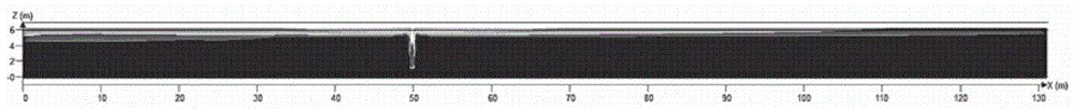
图4是本发明数值计算得到的气云浓度分布示意图;Fig. 4 is the gas cloud concentration distribution schematic diagram that numerical calculation of the present invention obtains;
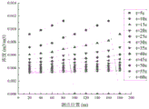
图5是本发明正演模型计算匀速运动泄漏源得到的各测点浓度计算结果示意图;Fig. 5 is a schematic diagram of the calculation results of the concentration of each measuring point obtained by the forward modeling model of the present invention to calculate the uniform motion leak source;
图6是本发明三维模拟计算匀速运动泄漏源得到的各测点浓度计算结果示意图;Fig. 6 is a schematic diagram of the calculation results of the concentration of each measuring point obtained by the three-dimensional simulation calculation of the uniform motion leakage source of the present invention;
图7是本发明泄漏源处于静止状态的泄漏源泄漏源位置反演结果示意图;Fig. 7 is a schematic diagram of the leakage source position inversion result of the leakage source in the static state of the present invention;
图8是本发明泄漏源处于匀速运动状态的泄漏源泄漏源强度反演结果示意图。Fig. 8 is a schematic diagram of leakage source strength inversion results of the leakage source in the state of uniform motion according to the present invention.
具体实施方式Detailed ways
如图1所示,是本发明一种隧道内天然气泄漏监测系统,它包括用于采集甲烷浓度的传感器1、光缆2、主机3、报警装置4和显示装置(图中没有画出),传感器1沿着隧道的长度方向间隔分布在隧道内壁上,主机3和报警装置4安装在一个机柜5内,传感器1为若干个并通过光缆2与主机3连接,主机3分别和报警装置4、显示装置相连,主机3包括控制单元、分别与之连接的泄漏源定位计算单元、泄漏源泄漏率反演计算单元和预警决策单元,其中,泄漏源定位计算单元根据甲烷浓度数据对泄漏源位置进行定位,泄漏源泄漏率反演计算单元根据甲烷浓度数据对泄漏源泄漏率进行计算,预警决策单元根据甲烷浓度数据控制报警装置的启停,泄漏源定位结果和泄漏源泄漏率计算结果均输出至显示装置上。As shown in Figure 1, it is a kind of natural gas leakage monitoring system in the tunnel of the present invention, and it comprises the sensor 1 that is used to collect methane concentration,
如图2所示,安装本发明隧道内天然气泄漏监测系统,具体是:As shown in Figure 2, the gas leakage monitoring system in the tunnel of the present invention is installed, specifically:
一、确定传感器在纵向上布置间距:1. Determine the vertical spacing of the sensors:
(1)根据隧道结构数据进行建模,本实施案例中的公路隧道数值实验模型的长(X)宽(Y)高(Z)分别为200m×6m×6m,用气体泄漏扩散数值模拟软件对隧道内部压缩天然气泄漏扩散过程进行数值模拟,以得到隧道内部泄漏燃气气云分布形态。(1) Modeling is carried out according to the tunnel structure data. The length (X), width (Y) and height (Z) of the highway tunnel numerical experimental model in this implementation case are 200m×6m×6m respectively, and the gas leakage and diffusion numerical simulation software is used to simulate Numerical simulation of the leakage and diffusion process of compressed natural gas inside the tunnel is carried out to obtain the distribution of the leaked gas cloud inside the tunnel.
(2)根据天然气泄漏扩散数值模拟得到的不同时刻的气云浓度分布,利用气体爆炸后果计算软件对气体爆炸后果进行数值实验,其计算结果如图4所示,利用气体爆炸后果计算软件对气体爆炸后果进行数值实验,以量化不同泄漏时长下隧道内发生气体爆炸产生的最大爆炸超压值。(2) According to the gas cloud concentration distribution at different times obtained from the numerical simulation of natural gas leakage and diffusion, the gas explosion consequence calculation software is used to conduct numerical experiments on the gas explosion consequences. The calculation results are shown in Figure 4. Numerical experiments were carried out to quantify the maximum explosion overpressure value generated by the gas explosion in the tunnel under different leakage durations.
(3)根据不同气云体积下的爆炸最大超压数值,映射到对应最大爆炸超压20KPa(人体轻伤)时的气云体积范围。(3) According to the maximum explosion overpressure value under different gas cloud volumes, it is mapped to the gas cloud volume range corresponding to the maximum explosion overpressure of 20KPa (slight injury to the human body).
(4)将此时可燃气云在隧道长度方向上的距离作为甲烷浓度传感器的布置间距,假设本案例得到的甲烷浓度传感器布置间距为20m,则本实施案例模型中共9个甲烷浓度传感器。(4) The distance of the combustible gas cloud in the tunnel length direction at this time is taken as the arrangement spacing of methane concentration sensors. Assuming that the arrangement spacing of methane concentration sensors obtained in this case is 20m, there are 9 methane concentration sensors in this implementation case model.
二、根据传感器在纵向上布置间距,对监测系统进行布置,并对数据进行实时监测。2. Arrange the monitoring system according to the vertical spacing of the sensors, and monitor the data in real time.
一种上述隧道内天然气泄漏监测系统的监测方法,具体包括以下步骤:A monitoring method of the above-mentioned natural gas leakage monitoring system in a tunnel, specifically comprising the following steps:
S1、槽车泄漏产生的甲烷气体在隧道内扩散时,传感器监测到实时甲烷浓度数据,通过光缆将甲烷浓度数据传输至主机;S1. When the methane gas produced by the leakage of the tanker diffuses in the tunnel, the sensor monitors the real-time methane concentration data, and transmits the methane concentration data to the host computer through the optical cable;
S2、主机接收甲烷浓度数据,通过预警决策单元对甲烷浓度数据进行判断,得到判定结果;预警决策单元判定的依据是:S2. The host computer receives the methane concentration data, judges the methane concentration data through the early warning decision-making unit, and obtains the judgment result; the basis for the judgment of the early warning decision-making unit is:

式中:Ci——第i个甲烷气体探测器测到的甲烷浓度;LEL——甲烷气体爆炸下限,5%。In the formula: C i — methane concentration measured by the ith methane gas detector; LEL — lower explosion limit of methane gas, 5%.
S3、报警装置对判定结果进行响应;S3. The alarm device responds to the determination result;
S4、主机内的泄漏源泄漏率反演计算单元对泄漏源泄漏率进行计算,泄漏源定位计算单元对泄漏源泄漏位置进行计算,并将泄漏源泄漏率计算结果和泄漏源定位结果输出到显示装置上。S4. The leakage source leakage rate inversion calculation unit in the main engine calculates the leakage source leakage rate, and the leakage source location calculation unit calculates the leakage source leakage position, and outputs the calculation result of the leakage source leakage rate and the leakage source location result to the display on the device.
如图3所示,计算泄漏源泄漏率和泄漏源泄漏位置具体包括:As shown in Figure 3, the calculation of the leakage rate of the leakage source and the location of the leakage source specifically includes:
(1)计算泄漏源处于静止状态时的流场正演分布,得到泄漏源处于静止状态时各监测点位置处燃气泄漏过程中不同时刻的浓度参数;(1) Calculate the forward distribution of the flow field when the leakage source is in a static state, and obtain the concentration parameters at different moments during the gas leakage process at each monitoring point when the leakage source is in a static state;
本实施例中,计算泄漏源强度分别为0.1kg/s、0.2kg/s、0.3kg/s、0.4kg/s、0.5kg/s、0.6kg/s、0.7kg/s、0.8kg/s、0.9kg/s、1.0kg/s时,泄漏位置为隧道空间内每隔5m的静止泄漏源流场正演分布。In this example, the calculated leakage source intensity is 0.1kg/s, 0.2kg/s, 0.3kg/s, 0.4kg/s, 0.5kg/s, 0.6kg/s, 0.7kg/s, 0.8kg/s , 0.9kg/s, 1.0kg/s, the leakage location is the forward modeling distribution of the static leakage source flow field every 5m in the tunnel space.
①在距离泄漏源沿纵向100m内的隧道段采用CFD三维数值模拟方法,分别对不同泄漏源强度与泄漏源位置处的隧道燃气泄漏浓度分布进行求解;①The CFD three-dimensional numerical simulation method is used in the tunnel section within 100m from the leakage source along the longitudinal direction, and the concentration distribution of the tunnel gas leakage at different leakage source intensities and leakage source locations are respectively solved;
②在距离泄漏源沿纵向100m以外的隧道段采用简化的一维气体扩散模型,采用时间前项、中心差分的方法对方程进行计算,编程求解不同泄漏源强度与泄漏源位置处的隧道燃气泄漏浓度分布;②A simplified one-dimensional gas diffusion model is used in the tunnel section away from the leakage source along the longitudinal direction of 100m, and the equation is calculated by using the method of time antecedent and central difference, and the tunnel gas leakage at different leakage source intensities and locations is solved by programming Concentration distribution;
③提取泄漏源处于静止状态时,由正演模型计算出的各监测点位置处燃气泄漏过程中的浓度参数,其中各测点每20s记录一次数据,泄漏持续时间为600s。③ Extract the concentration parameters during the gas leakage process at each monitoring point calculated by the forward modeling model when the leakage source is in a static state, where each measurement point records data every 20s, and the leakage duration is 600s.
(2)假设隧道内泄漏源从进入隧道开始至出隧道后一直处于匀速运动状态,计算泄漏源处于匀速运动状态时的流场正演分布,得到泄漏源处于匀速运动状态时各监测点位置处燃气泄漏过程中不同时刻的浓度参数;(2) Assuming that the leakage source in the tunnel has been in a state of uniform motion from entering the tunnel to exiting the tunnel, calculate the forward distribution of the flow field when the leakage source is in a state of uniform motion, and obtain the position of each monitoring point when the leakage source is in a state of uniform motion Concentration parameters at different moments during the gas leakage process;
本实施例中,计算隧道内泄漏源强度分别为0.1kg/s、0.2kg/s、0.3kg/s、0.4kg/s、0.5kg/s、0.6kg/s、0.7kg/s、0.8kg/s、0.9kg/s、1.0kg/s时,假设从进入隧道开始至出隧道后一直处于匀速运动状态,计算泄漏源处于运动状态时的流场正演分布。In this example, the calculated leakage source strength in the tunnel is 0.1kg/s, 0.2kg/s, 0.3kg/s, 0.4kg/s, 0.5kg/s, 0.6kg/s, 0.7kg/s, 0.8kg /s, 0.9kg/s, and 1.0kg/s, assuming that it is in a state of uniform motion from entering the tunnel to exiting the tunnel, calculate the forward distribution of the flow field when the leakage source is in motion.
①将隧道内连续释放的泄漏浓度场视作连续瞬时点源在一定时间序列下沿着隧道纵向长度范围内,当隧道长度为200m,隧道内连续释放的泄漏源强度为0.1kg/s时,将连续释放的泄漏源每隔一定距离5m视作一个点源,行车在隧道内的速度为60km/h,计算出每个点源泄漏量大小为
②采用一维气体扩散模型分别求解隧道内39个点源释放后的流场纵向浓度分布,泄漏持续时间为60s,每1s记录一个数据,其中泄漏源强度为0.9kg/s时,计算结果如图5所示。②A one-dimensional gas diffusion model is used to solve the longitudinal concentration distribution of the flow field after the release of 39 point sources in the tunnel. The leakage duration is 60s, and one data is recorded every 1s. When the leakage source intensity is 0.9kg/s, the calculation results are as follows: Figure 5 shows.
③获得泄漏源处于匀速运动状态时,由正演模型计算的各监测点位置处燃气泄漏过程中不同时刻的浓度参数。③ Obtain the concentration parameters at different moments during the gas leakage process at each monitoring point calculated by the forward modeling model when the leakage source is in a state of uniform motion.
采用三维数值实验的方法,得到各时刻各测点浓度分布,作为反演计算的传感器测量浓度值。对于隧道内静止状态泄漏源,隧道内泄漏浓度为0.26kg/s,泄漏源位置为50m;对于隧道内运动状态泄漏源,泄漏浓度为0.77kg/s,计算结果如图6所示。Using the method of three-dimensional numerical experiment, the concentration distribution of each measuring point at each time is obtained, which is used as the concentration value measured by the sensor for inversion calculation. For the leakage source in the static state in the tunnel, the leakage concentration in the tunnel is 0.26kg/s, and the location of the leakage source is 50m; for the leakage source in the moving state in the tunnel, the leakage concentration is 0.77kg/s, and the calculation results are shown in Figure 6.
(3)假设泄漏源强度和泄漏位置的先验分布函数为一定范围内的均匀分布函数;(3) Assume that the prior distribution function of the leakage source intensity and leakage location is a uniform distribution function within a certain range;
其计算式为:Its calculation formula is:

式中:In the formula:
p(Yk)——泄漏源强度的先验分布;p(Y k )——prior distribution of leakage source intensity;
Wmax——估计参数的上限值;W max - the upper limit of the estimated parameter;
Wmin——估计参数的下限值。W min ——The lower limit of the estimated parameter.
当泄漏源处于静止状态时,其泄漏源强度先验分布服从U[0,1],泄漏源位置先验分布服从U[0,200];当泄漏源处于匀速运动状态时,其泄漏源强度先验分布服从U[0,1]。When the leak source is in a static state, the prior distribution of the leak source intensity obeys U[0, 1], and the prior distribution of the leak source position obeys U[0, 200]; when the leak source is in a state of uniform motion, its leak source intensity The prior distribution obeys U[0,1].
(4)根据各传感器的观测数据计算泄漏源强度先验分布成立条件下的观测浓度分布的似然函数,其计算式为:(4) According to the observation data of each sensor, calculate the likelihood function of the observed concentration distribution under the condition that the prior distribution of the leakage source intensity is established, and the calculation formula is:

即:Right now:

其中

(5)结合先验分布、预测浓度和观测数据,利用贝叶斯定理计算源项泄漏率参数的后验分布近似解,p(Yk|β)=(p(Yk)p(β|Yk))/(p(β)),其中p(Yk)为先验分布,p(β|Yk)为似然函数。(5) Combining the prior distribution, predicted concentration and observation data, Bayesian theorem is used to calculate the approximate solution of the posterior distribution of the source leakage rate parameter, p(Y k |β)=(p(Y k )p(β| Y k ))/(p(β)), where p(Y k ) is the prior distribution, and p(β|Y k ) is the likelihood function.
(6)根据计算在各个泄漏源强度以及位置处概率值,进行曲线拟合,取拟合曲线概率极大值作为反演结果。对于静止状态泄漏源,其泄漏源位置反演结果如图7所示,泄漏源位置反演结果为39.95m,误差为10.05m,泄漏源强度反演结果为0.17kg/s,误差为0.07kg/s;对于泄漏源处于匀速运动状态,拟合后得到概率极大值对应的泄漏源强度为0.706kg/s,误差为0.064kg/s,其泄漏源强度反演结果如图8所示。(6) Carry out curve fitting according to the calculated probability values at each leakage source intensity and location, and take the maximum value of the probability of the fitting curve as the inversion result. For the leakage source in static state, the inversion result of the leakage source position is shown in Figure 7, the inversion result of the leakage source position is 39.95m, the error is 10.05m, the inversion result of the leakage source intensity is 0.17kg/s, and the error is 0.07kg /s; for the leakage source in a state of uniform motion, the leakage source intensity corresponding to the probability maximum value obtained after fitting is 0.706kg/s, and the error is 0.064kg/s. The inversion result of the leakage source intensity is shown in Figure 8.
本发明的实施方式不限于此,根据本发明的上述内容,按照本领域的普通技术知识和惯用手段,本发明还可以做出其它多种形式的修改、替换或变更,均落在本发明权利保护范围之内。The embodiments of the present invention are not limited thereto. According to the above content of the present invention, according to the common technical knowledge and conventional means in this field, the present invention can also make other various forms of modification, replacement or change, all of which fall within the rights of the present invention. within the scope of protection.
Claims (9)


Applications Claiming Priority (2)
| Application Number | Priority Date | Filing Date | Title |
|---|---|---|---|
| CN2022104666834 | 2022-04-29 | ||
| CN202210466683 | 2022-04-29 |
Publications (2)
| Publication Number | Publication Date |
|---|---|
| CN115773473A true CN115773473A (en) | 2023-03-10 |
| CN115773473B CN115773473B (en) | 2024-06-04 |
Family
ID=85388519
Family Applications (1)
| Application Number | Title | Priority Date | Filing Date |
|---|---|---|---|
| CN202211245123.2A Active CN115773473B (en) | 2022-04-29 | 2022-10-10 | Monitoring system and monitoring method for natural gas leakage in tunnel |
Country Status (1)
| Country | Link |
|---|---|
| CN (1) | CN115773473B (en) |
Cited By (2)
| Publication number | Priority date | Publication date | Assignee | Title |
|---|---|---|---|---|
| CN117034740A (en) * | 2023-07-10 | 2023-11-10 | 重庆大学 | Method and system for locating combustible gas leakage sources and predicting leakage rates in tunnels |
| CN117169424A (en) * | 2023-07-17 | 2023-12-05 | 中铁第一勘察设计院集团有限公司 | A tunnel harmful gas monitoring system and method |
Citations (13)
| Publication number | Priority date | Publication date | Assignee | Title |
|---|---|---|---|---|
| EP1220181A1 (en) * | 2000-12-30 | 2002-07-03 | Goddert Peters | Tunnel monitoring system in a tunnel |
| US20100013627A1 (en) * | 2008-07-17 | 2010-01-21 | General Electric Company | System and method for monitoring infrastructure |
| CN201575308U (en) * | 2009-09-02 | 2010-09-08 | 胜利油田胜利工程设计咨询有限责任公司 | Laser monitoring device for natural gas leakage in open space of tunnel |
| CN103196038A (en) * | 2013-03-14 | 2013-07-10 | 清华大学 | Real-time positioning analysis method and system for fuel gas pipeline network leakage source |
| CN109140242A (en) * | 2018-09-12 | 2019-01-04 | 哈尔滨工业大学 | A kind of pipe gallery combustion gas cabin on-line monitoring and ventilated linked control method |
| WO2019018947A1 (en) * | 2017-07-28 | 2019-01-31 | Hifi Engineering Inc. | Methods and systems for providing access to interferometric system data |
| CN111256043A (en) * | 2020-03-18 | 2020-06-09 | 南京工业大学 | Identification method of gas leakage source in integrated pipe gallery based on impulse response method and sensor array |
| CN111521728A (en) * | 2020-05-15 | 2020-08-11 | 福州大学 | Gas blasting pipeline experimental device and method with multi-dimensional concentration gradient |
| CN211292759U (en) * | 2019-12-19 | 2020-08-18 | 南京工业大学 | An adjustable rail sensor connection device for measuring the overpressure of the nozzle |
| WO2021005649A1 (en) * | 2019-07-05 | 2021-01-14 | 日本電気株式会社 | Optical fiber sensing system, optical fiber sensing apparatus, and underground activity monitoring method |
| CN112733312A (en) * | 2019-10-10 | 2021-04-30 | 中国石油化工股份有限公司 | Natural gas gathering and transportation pipeline leakage simulation device and simulation method |
| CN112966378A (en) * | 2021-03-04 | 2021-06-15 | 浙大城市学院 | Hydrogen leakage prediction method and system based on safety evaluation model |
| CN114377319A (en) * | 2021-01-27 | 2022-04-22 | 福州大学 | Pipe gallery gas explosion suppression method and device and pipe gallery explosion suppression simulation experiment system |
-
2022
- 2022-10-10 CN CN202211245123.2A patent/CN115773473B/en active Active
Patent Citations (13)
| Publication number | Priority date | Publication date | Assignee | Title |
|---|---|---|---|---|
| EP1220181A1 (en) * | 2000-12-30 | 2002-07-03 | Goddert Peters | Tunnel monitoring system in a tunnel |
| US20100013627A1 (en) * | 2008-07-17 | 2010-01-21 | General Electric Company | System and method for monitoring infrastructure |
| CN201575308U (en) * | 2009-09-02 | 2010-09-08 | 胜利油田胜利工程设计咨询有限责任公司 | Laser monitoring device for natural gas leakage in open space of tunnel |
| CN103196038A (en) * | 2013-03-14 | 2013-07-10 | 清华大学 | Real-time positioning analysis method and system for fuel gas pipeline network leakage source |
| WO2019018947A1 (en) * | 2017-07-28 | 2019-01-31 | Hifi Engineering Inc. | Methods and systems for providing access to interferometric system data |
| CN109140242A (en) * | 2018-09-12 | 2019-01-04 | 哈尔滨工业大学 | A kind of pipe gallery combustion gas cabin on-line monitoring and ventilated linked control method |
| WO2021005649A1 (en) * | 2019-07-05 | 2021-01-14 | 日本電気株式会社 | Optical fiber sensing system, optical fiber sensing apparatus, and underground activity monitoring method |
| CN112733312A (en) * | 2019-10-10 | 2021-04-30 | 中国石油化工股份有限公司 | Natural gas gathering and transportation pipeline leakage simulation device and simulation method |
| CN211292759U (en) * | 2019-12-19 | 2020-08-18 | 南京工业大学 | An adjustable rail sensor connection device for measuring the overpressure of the nozzle |
| CN111256043A (en) * | 2020-03-18 | 2020-06-09 | 南京工业大学 | Identification method of gas leakage source in integrated pipe gallery based on impulse response method and sensor array |
| CN111521728A (en) * | 2020-05-15 | 2020-08-11 | 福州大学 | Gas blasting pipeline experimental device and method with multi-dimensional concentration gradient |
| CN114377319A (en) * | 2021-01-27 | 2022-04-22 | 福州大学 | Pipe gallery gas explosion suppression method and device and pipe gallery explosion suppression simulation experiment system |
| CN112966378A (en) * | 2021-03-04 | 2021-06-15 | 浙大城市学院 | Hydrogen leakage prediction method and system based on safety evaluation model |
Non-Patent Citations (8)
| Title |
|---|
| WANG K,LI C,JIA W: "Study on multicomponent leakage and diffusioncharacteristics of hydrogen-blended natural gas in utility tunnels", INTERNATIONAL JOURNAL OF HYDROGEN ENERGY, vol. 50, 2 January 2024 (2024-01-02), pages 740 - 760, XP087439619, DOI: 10.1016/j.ijhydene.2023.06.262 * |
| 刘全义;苏伯尼;王晟;黄弘;张辉;吴秀敏;: "基于无线传感器网络的气体泄漏源快速定位方法研究", 中国安全科学学报, no. 01, 15 January 2013 (2013-01-15) * |
| 彭世尼;段萍;: "LNG泄露后果的预测模型", 重庆大学学报(自然科学版), no. 01, 28 January 2006 (2006-01-28) * |
| 李新宏;朱红卫;陈国明;王向南;康前前;: "公路隧道内CNG管束气瓶车泄漏天然气扩散CFD仿真", 中国安全生产科学技术, no. 12, 30 December 2016 (2016-12-30) * |
| 郭少冬;杨锐;翁文国;: "基于MCMC方法的城区有毒气体扩散源反演", 清华大学学报(自然科学版)网络.预览, no. 05, 15 March 2009 (2009-03-15) * |
| 马世海;黄平;代鹏飞;李想;: "隧道内液化天然气管道泄漏爆炸过程的数值模拟", 科技导报, no. 22, 8 August 2011 (2011-08-08) * |
| 黄小美;张婧;周阳;张琼雅;: "街道天然气管道泄漏扩散的数值模拟分析", 煤气与热力, no. 02, 15 February 2016 (2016-02-15) * |
| 黄小美;彭世尼;徐海东;杨茂华;: "燃气管道泄漏流量的计算", 煤气与热力, no. 03, 15 March 2008 (2008-03-15) * |
Cited By (2)
| Publication number | Priority date | Publication date | Assignee | Title |
|---|---|---|---|---|
| CN117034740A (en) * | 2023-07-10 | 2023-11-10 | 重庆大学 | Method and system for locating combustible gas leakage sources and predicting leakage rates in tunnels |
| CN117169424A (en) * | 2023-07-17 | 2023-12-05 | 中铁第一勘察设计院集团有限公司 | A tunnel harmful gas monitoring system and method |
Also Published As
| Publication number | Publication date |
|---|---|
| CN115773473B (en) | 2024-06-04 |
Similar Documents
| Publication | Publication Date | Title |
|---|---|---|
| CN103914622B (en) | A kind of chemical leakage fast prediction alarm emergency response decision-making method | |
| CN115773473A (en) | Monitoring system and monitoring method for natural gas leakage in tunnel | |
| CN108805472A (en) | A kind of the highway transportation method for early warning and system of tank container | |
| CN105957293B (en) | Fire monitoring method and its system during a kind of nuclear power plant containment shell bulge test | |
| CN114321740A (en) | Combustible gas leakage point positioning method and system and readable storage module | |
| CN113609925A (en) | LNG loading and unloading operation safety management and control system and illegal behavior identification method | |
| CN114519304A (en) | Multi-target fire scene temperature prediction method based on distributed optical fiber temperature measurement | |
| CN109099962A (en) | A kind of real-time monitoring system of historical building | |
| CN204188341U (en) | Air pressure testing/detecting device | |
| CN117763934A (en) | Micro pipe gallery gas monitoring method and system based on deep learning | |
| CN109272162A (en) | It is a kind of based on the security protection forecasting system and method that fire index | |
| CN116446953A (en) | Polymorphic display coal spontaneous combustion early warning method based on coal mine underground regional characteristics | |
| CN119811013A (en) | A mine early warning method, system and computer equipment based on multi-system collaboration | |
| CN104863634A (en) | Performance detecting method of tunnel fire-fighting equipment | |
| Shen et al. | Numerical simulation of CO distribution discharged by flame-proof vehicle in underground tunnel of coal mine | |
| CN105632114A (en) | Monitoring measurement point safety state monitoring method based on GIS technology | |
| Blake et al. | Aircraft cargo compartment fire detection and smoke transport modeling | |
| CN117173808A (en) | A smart shopping mall inspection method and system based on the Internet of Things | |
| CN108760354A (en) | Train carries analog detection method, system and the medium that burning things which may cause a fire disaster operation flue gas transports | |
| CN116706296A (en) | Method and device for monitoring thermal runaway of battery system | |
| CN104200599A (en) | Bus multi-sensor fire detection method | |
| CN108661717B (en) | Spontaneous combustion early warning system for open-air coal | |
| CN109738382A (en) | Intelligent detection device and detection method for air pollution caused by automobile exhaust | |
| CN110427000B (en) | Intelligent management and control system for point-by-point grading plans of chemical plants | |
| CN206256930U (en) | A kind of safety pre-warning system of constructing tunnel |
Legal Events
| Date | Code | Title | Description |
|---|---|---|---|
| PB01 | Publication | ||
| PB01 | Publication | ||
| SE01 | Entry into force of request for substantive examination | ||
| SE01 | Entry into force of request for substantive examination | ||
| GR01 | Patent grant | ||
| GR01 | Patent grant |