CN115869112B - Clamping device, clamping system and using method thereof - Google Patents
Clamping device, clamping system and using method thereof Download PDFInfo
- Publication number
- CN115869112B CN115869112B CN202310045442.7A CN202310045442A CN115869112B CN 115869112 B CN115869112 B CN 115869112B CN 202310045442 A CN202310045442 A CN 202310045442A CN 115869112 B CN115869112 B CN 115869112B
- Authority
- CN
- China
- Prior art keywords
- clamping
- hollow structure
- piece
- clamping device
- accommodating space
- Prior art date
- Legal status (The legal status is an assumption and is not a legal conclusion. Google has not performed a legal analysis and makes no representation as to the accuracy of the status listed.)
- Active
Links
- 238000000034 method Methods 0.000 title abstract description 14
- 238000002955 isolation Methods 0.000 claims abstract description 37
- 206010067171 Regurgitation Diseases 0.000 claims abstract description 12
- 230000000712 assembly Effects 0.000 claims abstract description 12
- 238000000429 assembly Methods 0.000 claims abstract description 12
- 239000000463 material Substances 0.000 claims description 13
- 229910001000 nickel titanium Inorganic materials 0.000 claims description 7
- HZEWFHLRYVTOIW-UHFFFAOYSA-N [Ti].[Ni] Chemical compound [Ti].[Ni] HZEWFHLRYVTOIW-UHFFFAOYSA-N 0.000 claims description 6
- 229910052751 metal Inorganic materials 0.000 claims description 5
- 239000002184 metal Substances 0.000 claims description 5
- 229920001225 polyester resin Polymers 0.000 claims description 3
- 239000004645 polyester resin Substances 0.000 claims description 3
- -1 polytetrafluoroethylene Polymers 0.000 claims description 3
- 229920001343 polytetrafluoroethylene Polymers 0.000 claims description 3
- 239000004810 polytetrafluoroethylene Substances 0.000 claims description 3
- 238000009954 braiding Methods 0.000 claims description 2
- 230000002349 favourable effect Effects 0.000 abstract description 6
- 230000004308 accommodation Effects 0.000 description 11
- 230000009286 beneficial effect Effects 0.000 description 11
- 210000004115 mitral valve Anatomy 0.000 description 10
- 241000446313 Lamella Species 0.000 description 8
- 210000000591 tricuspid valve Anatomy 0.000 description 8
- 230000001105 regulatory effect Effects 0.000 description 7
- 238000005520 cutting process Methods 0.000 description 6
- 238000004519 manufacturing process Methods 0.000 description 6
- 238000010992 reflux Methods 0.000 description 6
- 208000031481 Pathologic Constriction Diseases 0.000 description 5
- 238000010586 diagram Methods 0.000 description 5
- 230000036262 stenosis Effects 0.000 description 5
- 208000037804 stenosis Diseases 0.000 description 5
- 230000017531 blood circulation Effects 0.000 description 4
- 239000008280 blood Substances 0.000 description 3
- 210000004369 blood Anatomy 0.000 description 3
- 230000007246 mechanism Effects 0.000 description 3
- 201000001943 Tricuspid Valve Insufficiency Diseases 0.000 description 2
- 210000003191 femoral vein Anatomy 0.000 description 2
- 210000002837 heart atrium Anatomy 0.000 description 2
- 210000005240 left ventricle Anatomy 0.000 description 2
- 208000005907 mitral valve insufficiency Diseases 0.000 description 2
- 210000005241 right ventricle Anatomy 0.000 description 2
- 210000000709 aorta Anatomy 0.000 description 1
- 210000001765 aortic valve Anatomy 0.000 description 1
- 210000004204 blood vessel Anatomy 0.000 description 1
- 230000006835 compression Effects 0.000 description 1
- 238000007906 compression Methods 0.000 description 1
- 230000003750 conditioning effect Effects 0.000 description 1
- 230000008602 contraction Effects 0.000 description 1
- 230000007423 decrease Effects 0.000 description 1
- 230000007547 defect Effects 0.000 description 1
- 230000000694 effects Effects 0.000 description 1
- 230000036541 health Effects 0.000 description 1
- 238000009998 heat setting Methods 0.000 description 1
- 238000003698 laser cutting Methods 0.000 description 1
- 210000005246 left atrium Anatomy 0.000 description 1
- HLXZNVUGXRDIFK-UHFFFAOYSA-N nickel titanium Chemical compound [Ti].[Ti].[Ti].[Ti].[Ti].[Ti].[Ti].[Ti].[Ti].[Ti].[Ti].[Ni].[Ni].[Ni].[Ni].[Ni].[Ni].[Ni].[Ni].[Ni].[Ni].[Ni].[Ni].[Ni].[Ni] HLXZNVUGXRDIFK-UHFFFAOYSA-N 0.000 description 1
- 239000002861 polymer material Substances 0.000 description 1
- 230000008569 process Effects 0.000 description 1
- 210000001147 pulmonary artery Anatomy 0.000 description 1
- 210000003102 pulmonary valve Anatomy 0.000 description 1
- 210000005245 right atrium Anatomy 0.000 description 1
Images




Landscapes
- Prostheses (AREA)
Abstract
The embodiment of the application provides a clamping device, a clamping system and a using method thereof. The clamping device comprises an isolated hollow structure, an adjusting piece and two clamping assemblies. The isolation hollow structure comprises a first part and a second part, wherein the first accommodating space enclosed by the first part is communicated with the second accommodating space enclosed by the second part; the isolated hollow structure is configured to be disposed in the valve regurgitation region. When the clamping device is in the first state, the adjusting piece is positioned in the first accommodating space. At least part of the two clamping assemblies are oppositely arranged at the outer side of the second part. When the clamping device is in the second state, the adjusting piece moves from the first accommodating space to the second accommodating space, so that the second part expands outwards in a direction away from the central shaft of the isolation hollow structure, and the clamping assembly deflects outwards by a preset angle. This application sets up between two clamping components and keeps apart hollow structure, is favorable to reducing the tension of valve leaflet, and then is favorable to reducing the risk of valve leaflet tearing.
Description
Technical Field
The application relates to the technical field of interventional medical devices, in particular to a clamping device, a clamping system and a using method thereof.
Background
Four valves are provided in the heart, namely an aortic valve connecting the left ventricle with the aorta, a pulmonary valve connecting the right ventricle with the pulmonary artery, a mitral valve connecting the left atrium with the left ventricle and a tricuspid valve connecting the right atrium with the right ventricle, and all act as one-way valves, so that blood can only flow from one direction to the other direction and cannot flow backwards. Each valve is made up of at least one leaflet, the opening and closing between the leaflets acting to open and close the blood passageway. When the valve is diseased, blood reflux easily occurs, and life and health of a patient are seriously threatened.
At present, a clamping device is used for clamping and fixing the free edges of the valve leaflets, so that the valve leaflets are closed at the end stage of systole, and reflux is reduced. However, the conventional clamping device has a problem that valve stenosis is easily caused during diastole of the valve or that the valve leaflet is easily torn.
Disclosure of Invention
The application provides a clamping device, a clamping system and a using method thereof aiming at the defects of the existing mode, and aims to solve the technical problems that the existing clamping device is easy to cause valve stenosis in the diastole of a valve or the valve leaflet is easy to tear.
In a first aspect, embodiments of the present application provide a clamping device comprising:
the isolation hollow structure comprises a first part and a second part, wherein a first accommodating space enclosed by the first part is communicated with a second accommodating space enclosed by the second part; the isolated hollow structure is configured to be disposed in a valve regurgitation region;
the adjusting piece is positioned in the first accommodating space when the clamping device is in the first state;
two clamping assemblies, at least part of which are oppositely arranged outside the second part;
when the clamping device is in the second state, the adjusting piece moves from the first accommodating space to the second accommodating space, so that the second part expands outwards in a direction away from the central axis of the isolation hollow structure, and the clamping assembly deflects outwards by a preset angle.
Optionally, when the clamping device does not clamp the clamped part, the width of the second part of the isolation hollow structure away from the end face of the first part gradually decreases along the direction perpendicular to the longitudinal section of the isolation hollow structure from the first part to the second part;
the longitudinal section of the adjusting piece is trapezoid.
Optionally, the isolated hollow structure is a grid hollow structure with shape memory.
Optionally, the clamping assembly comprises a first clamping member; the longitudinal section of the first clamping piece is U-shaped, and one end of the first clamping piece is provided with an opening, and the direction of the opening is from the first part to the second part;
the first clamping piece comprises a fixing part, a connecting part and a first clamping part, and at least part of the fixing part is connected with the outer side of the second part; the fixing part is connected with the first clamping part through the connecting part.
Optionally, the clamping assembly further comprises a second clamping member disposed between the fixing portion and the first clamping portion, the second clamping member comprising a second clamping portion; the first end of the second clamping part is connected with the connecting part;
when the clamping device is in a second state, the second end of the second clamping part is attached to the first clamping part;
when the clamping device is in a third state, the second end of the second clamping part is driven to move from the first clamping part to the fixing part, and a clamping space is formed between the second clamping part and the first clamping part.
Optionally, the second clamping member further comprises a plurality of barbs, the barbs being arranged on a side of the second clamping portion facing the first clamping portion.
Optionally, the clamping device further comprises a connecting piece and at least one supporting piece, wherein the supporting piece is arranged on one side of the first part far away from the second part, and two ends of the supporting piece are connected with the first part;
the connecting piece is arranged at the geometric center of the supporting piece;
during the transportation of the clamping device, the connecting piece and the supporting piece are driven to bend towards the inside of the isolated hollow structure.
Optionally, the clamping device further comprises at least one of:
the isolation hollow structure is obtained by braiding nickel titanium wires;
the material of the first clamping piece and/or the second clamping piece of the clamping assembly comprises nickel-titanium metal;
the isolating hollow structure and the surface of the clamping component are both provided with films, and the materials of the films comprise at least one of polyester resin and polytetrafluoroethylene.
In a second aspect, embodiments of the present application provide a clamping system comprising a conveying device and the clamping device provided in the first aspect; the conveying device comprises an operating piece, a first driving piece and a second driving piece, wherein the operating piece is detachably connected with a connecting piece of the clamping device, the first driving piece is detachably connected with a second end of a second clamping part of the clamping device, and the second driving piece is detachably connected with the adjusting piece.
In a third aspect, embodiments of the present application provide a method for using a clamping system, including:
the operating member drives the connecting member and the supporting member to bend towards the inside of the isolated hollow structure to deliver the clamping device to the valve regurgitation area through the catheter of the delivery device;
the second driving piece drives the adjusting piece to move from a first accommodating space enclosed by the first part of the isolation hollow structure to a second accommodating space enclosed by the second part, so that the second part expands outwards in a direction away from the central axis of the isolation hollow structure, and the clamping assembly deflects outwards by a preset angle;
the first driving piece drives the second end of the second clamping part of the clamping assembly to move along the direction from the first clamping part to the fixed part, so that a clamping space is formed between the second clamping part and the first clamping part, and the clamped part enters the clamping space;
the second driving member is removed, the second portion contracts, the compression adjustment member moves from the second receiving space to the first receiving space, the second portion contracts inwardly in a direction approaching the central axis of the insulating hollow structure, and the clamping assembly deflects inwardly.
The beneficial technical effects that technical scheme that this application embodiment provided brought include:
the isolation hollow structure is a hollow structure and is divided into a first accommodating space and a second accommodating space; through setting up the regulating part in the inside of keeping apart hollow structure, the regulating part moves in first accommodation space and second accommodation space to the second part of adjusting keep apart hollow structure keeps away from the width of the terminal surface of first part, and then adjusts the angle of clamping assembly, in order to the clamping assembly clamp by the centre gripping position. After the two clamping components clamp the valve leaflet, the isolation hollow structure is arranged between the two clamping components, so that the distance from the valve leaflet to the center can be reduced, the tension of the valve leaflet can be reduced, and the risk of tearing the valve leaflet and the risk of stenosis of a flap opening can be reduced. Meanwhile, after the clamping assembly clamps the valve blades, the isolating hollow structure has a certain width, so that the isolating hollow structure can also block blood flow reflux.
Moreover, the adjusting piece is arranged in the isolating hollow structure, and the inclination angle of the clamping assembly can be adjusted through the internal movement of the adjusting piece in the isolating hollow structure so as to clamp the clamped part. The clamping device does not need to be provided with a complex and precise mechanical locking mechanism and the like to adjust the clamping assembly, and the clamping device is simple in production process and low in production cost.
Additional aspects and advantages of the application will be set forth in part in the description which follows, and in part will be obvious from the description, or may be learned by practice of the application.
Drawings
The foregoing and/or additional aspects and advantages of the present application will become apparent and readily appreciated from the following description of the embodiments, taken in conjunction with the accompanying drawings, in which:
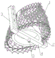
fig. 1 is a schematic structural diagram of a first view angle of a clamping device according to an embodiment of the present application;
fig. 2 is a schematic structural diagram of a second view angle of a clamping device according to an embodiment of the present application;
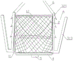
fig. 3 is a schematic structural view of a clamping device in a first state according to an embodiment of the present application;
fig. 4 is a schematic structural view of a clamping device in a third state according to an embodiment of the present application;
fig. 5 is a schematic structural diagram of a first view angle of an adjusting member according to an embodiment of the present application;
FIG. 6 is a schematic view of a second view of an adjusting member according to an embodiment of the present disclosure;
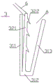
fig. 7 is a schematic structural diagram of a clamping assembly of a clamping device in a first state according to an embodiment of the present application;
fig. 8 is a schematic structural view of a clamping assembly of the clamping device in a third state according to the embodiment of the present application;
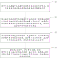
fig. 9 is a flow chart of a method for using the clamping system according to the embodiment of the present application.
Reference numerals illustrate:
1-isolating the hollow structure; 11-a first part; 12-a second part;
2-an adjusting member; 21-cutting face; 22-an operation hole;
a 3-clamp assembly;
31-a first clamping member; 311-fixing part; 312-connecting part; 313-a first nip;
32-a second clamping member; 321-a second nip; 322-barb; a-clamping space;
4-a support;
a 5-connector;
6-first driving member.
Detailed Description
Embodiments of the present application are described below with reference to the drawings in the present application. It should be understood that the embodiments described below with reference to the drawings are exemplary descriptions for explaining the technical solutions of the embodiments of the present application, and the technical solutions of the embodiments of the present application are not limited.
As used herein, the singular forms "a", "an", "the" and "the" are intended to include the plural forms as well, unless expressly stated otherwise, as understood by those skilled in the art. It will be further understood that the terms "comprises" and/or "comprising," when used in this specification, specify the presence of stated features, integers, steps, operations, elements, and/or components, but do not preclude the presence or addition of other features, information, data, steps, operations, elements, components, and/or groups thereof, etc. that may be implemented as desired in the art. The term "and/or" as used herein refers to at least one of the items defined by the term, e.g., "a and/or B" may be implemented as "a", or as "B", or as "a and B".
For the purpose of making the objects, technical solutions and advantages of the present application more apparent, the embodiments of the present application will be described in further detail below with reference to the accompanying drawings.
The following describes the technical solutions of the present application and how the technical solutions of the present application solve the above technical problems in detail with specific embodiments. It should be noted that the following embodiments may be referred to, or combined with each other, and the description will not be repeated for the same terms, similar features, similar implementation steps, and the like in different embodiments.
The embodiment of the application provides a clamping device, and the structural schematic diagram of the clamping device is shown in fig. 1 to 8, and the clamping device comprises an isolated hollow structure 1, an adjusting piece 2 and two clamping assemblies 3.
The isolating hollow structure 1 comprises a first part 11 and a second part 12, wherein a first accommodating space enclosed by the first part 11 is communicated with a second accommodating space enclosed by the second part 12; the isolation hollow structure 1 is configured to be disposed in the valve regurgitation region.
When the clamping device is in the first state, the adjusting member 2 is located in the first accommodating space.
At least part of the two clamping assemblies 3 are arranged opposite to the outside of the second part 12.
When the clamping device is in the second state, the adjusting member 2 moves from the first accommodation space to the second accommodation space, so that the second portion 12 expands outwards in a direction away from the central axis of the insulating hollow structure 1, and the clamping assembly 3 deflects outwards by a preset angle.
The clamped portion may be a mitral valve or a tricuspid valve leaflet. The first state is the initial state of the clamping device (as shown in fig. 3); the second state is a state (not shown) after the adjusting member 2 moves from the first accommodation space to the second accommodation space when the clamping device is to clamp the clamped member.
In this embodiment, the isolation hollow structure 1 is a hollow structure, and is divided into a first accommodating space and a second accommodating space; through setting up regulating part 2 in the inside of keeping apart hollow structure 1, regulating part 2 moves in first accommodation space and second accommodation space to the width of keeping away from the terminal surface of first part 11 of second part 12 of adjusting keep apart hollow structure 1, and then the angle of adjustment clamping assembly 3, in order that clamping assembly 3 clamp by the centre gripping position. Specifically, when the clamping device is in the first state, the adjusting member 2 is in the first accommodation space, and the width of the end face of the second portion 12 is smaller than the width of the end face of the first portion 11, and the clamping assembly 3 is inclined inward; when the clamping device is in the second state, the adjusting piece 2 is driven to move from the first accommodating space to the second accommodating space, the second part 12 is outwards expanded by the adjusting piece 2 in a direction away from the central axis of the isolation hollow structure 1, so that the second part 12 is outwards expanded, the clamping assembly 3 is outwards inclined, and the clamped part of the clamping assembly 3 is conveniently clamped; after the clamping is completed, after the external force is removed, the second part 12 of the isolation hollow structure 1 compresses the adjusting piece 2 to return to the first accommodating space from the second accommodating space due to the self-contraction acting force, and the first part 11 of the isolation hollow structure 1 contracts inwards, so that the clamping assembly 3 is driven to incline inwards.
This application after two clamp assemblies 3 clamp the lamella, because of setting up between two clamp assemblies 3 keeps apart hollow structure 1, can reduce the distance that the lamella is drawn close to the center from this, be favorable to reducing the tension of lamella, and then be favorable to reducing the risk of lamella tearing and reduce the narrow risk of lamella mouth. Meanwhile, after the clamping assembly 3 clamps the valve blades, the isolating hollow structure 1 can also block blood flow reflux due to the fact that the isolating hollow structure 1 has a certain width.
Moreover, the adjusting piece 2 is arranged in the isolating hollow structure 1, and the inclination angle of the clamping assembly 3 can be adjusted by the internal movement of the adjusting piece 2 in the isolating hollow structure 1 so as to clamp the clamped part. The clamping device does not need to be provided with a complex and precise mechanical locking mechanism and the like to adjust the clamping assembly 3, and the clamping device is simple in production process and low in production cost.
Illustratively, as shown in fig. 1 and 3, when the clamping device is in the first state, the isolating hollow structure 1 is in a shape of narrow upper part and wide lower part, the adjusting member 2 is positioned in the first accommodating space, and the clamping assembly 3 is inclined inwards. When the clamping device is in the second state, the adjusting piece 2 is driven to move from the first accommodating space to the second accommodating space, and at the moment, the second part 12 is expanded by the adjusting piece 2, so that the second part 12 is outwards expanded, the end face of the second part 12 is widened, the clamping assembly 3 is driven to outwards deflect by a preset angle, and the clamped part can be conveniently clamped.
Alternatively, in the first state of the clamping device, the width of the end face of the second portion 12 of the insulating hollow structure 1 facing away from the first portion 11 is gradually reduced from the first portion 11 to said second portion 12 in a direction perpendicular to the longitudinal section of the insulating hollow structure 1. The longitudinal section of the adjusting member 2 is trapezoidal.
In this embodiment, the width of the end surface of the second portion 12 of the insulating hollow structure 1, which is far away from the first portion 11, is gradually reduced, so that the insulating hollow structure 1 is in a shape of narrow top and wide bottom, which is beneficial to the outward expansion of the second portion 12 after the adjusting member 2 moves in the insulating hollow structure 1 to the second accommodating space surrounded by the second portion 12, so as to drive the clamping assembly 3 to deflect outwards.
The longitudinal section of the adjusting member 2 is trapezoidal, the adjusting member 2 is placed in the first accommodating space, and the first portion 11 and the adjusting member 2 follow the shape, so that the width of the end face of the first portion 11 is gradually reduced.
Alternatively, the isolated hollow structure 1 is a mesh hollow structure with shape memory.
In this embodiment, the material of the insulating hollow structure 1 is an elastic memory material, and the second portion 12 of the insulating hollow structure 1 can be restored to the original shape after the adjusting member 2 returns from the second accommodating space to the first accommodating space. The isolated hollow structure 1 can be compressed for delivery when the isolated hollow structure 1 is passed through a conduit of a delivery system; after the isolated hollow structure 1 is delivered to the valve regurgitation area, the isolated hollow structure 1 can be restored to the original shape, so that the clamping device can be delivered by a small-size delivery system, can meet transvascular access, and can be used for treating mitral valve and tricuspid valve regurgitation skin.
Alternatively, the insulating hollow structure 1 is woven from nickel titanium wire.
Alternatively, the cross section of the isolation hollow structure 1 is elliptical; two clamping assemblies 3 are oppositely arranged on two sides of the long axis of the ellipse.
In this embodiment, after the adjusting member 2 reaches the second accommodating space, the adjusting member 2 outwards expands the second portion 12 of the isolating hollow structure 1, and since the two clamping assemblies 3 are oppositely disposed at two sides of the major axis of the ellipse, the outwards deflected angle of the two clamping assemblies 3 is larger, which can be beneficial to clamping the clamped portion.
Optionally, the adjustment member 2 comprises an operating aperture 22.
In this embodiment, as shown in fig. 5 and 6, the second driving member can be detachably connected to the regulating member 2 through the operation hole 22. After the second driving member drives the adjusting member 2 from the first accommodating space to the second accommodating space and clamps the clamped part, the second driving member is removed, and the second portion 12 of the isolation hollow structure 1 is pressed by the second driving member to return the adjusting member 2 from the second accommodating space to the first accommodating space due to the self-contraction acting force, so that the isolation hollow structure 1 is restored to the original shape. Moreover, when the second portion 12 of the isolated hollow structure 1 presses the adjusting member 2, the adjusting member 2 is more easily pressed by the contraction force of the second portion to move into the first accommodating space due to the trapezoid longitudinal section of the adjusting member 2.
Optionally, the conditioning element 2 further comprises at least one cutting face 21.
In this embodiment, as shown in fig. 5 and 6, the adjusting member 2 includes a cutting face 21. The adjusting member 2 has a cutting elliptical shape with a narrow upper part and a wide lower part. When the adjusting member 2 moves from the first accommodating space to the second accommodating space, the cutting surface 21 of the adjusting member 2 causes the second portion 12 to gradually expand outwards along with the cutting surface 21, which is beneficial to avoiding the second portion 12 from being damaged due to the fact that the second portion 12 expands outwards to a large extent at a time.
Alternatively, the regulating member 2 has an elliptic cylindrical structure with a narrow upper part and a wide lower part.
Optionally, the clamping assembly 3 comprises a first clamping member 31; the longitudinal section of the first clamping member 31 is U-shaped with one end open, the direction of the opening being from the first portion 11 to the second portion 12.
The first clamping member 31 includes a fixing portion 311, a connecting portion 312, and a first clamping portion 313, at least a portion of the fixing portion 311 being connected to the outside of the second portion 12; the fixing portion 311 is connected to the first nip portion 313 via a connecting portion 312.
In this embodiment, one end of the fixing portion 311 is connected to one end of the first clamping portion 313 through the connecting portion 312, and the other end of the fixing portion 311 is not connected to the other end of the first clamping portion 313, so as to form an opening.
Illustratively, as shown in fig. 3, the fixing portion 311 of the first clamping member 31 is connected to the outer sides of both the first portion 11 and the second portion 12 of the insulating hollow structure 1, so that the stability between the first clamping member 31 and the insulating hollow structure 1 can be increased.
Optionally, the clamping assembly 3 further includes a second clamping member 32 disposed between the fixing portion 311 and the first clamping portion 313, the second clamping member 32 including a second clamping portion 321; the first end of the second clamping portion 321 is connected to the connecting portion 312.
When the clamping device is in the second state, the second end of the second clamping portion 321 is attached to the first clamping portion 313.
When the clamping device is in the third state, the second end of the second clamping portion 321 is driven to move from the first clamping portion 313 to the fixing portion 311, and a clamping space A is formed between the second clamping portion 321 and the first clamping portion 313.
In this embodiment, when the clamping device is in the second state, one end of the second clamping portion 321 is connected to the connecting portion 312, and a V-shape is formed between one end of the second clamping portion 321 and one end of the fixing portion 311, so that a clamping space a between the second clamping portion 321 and the first clamping portion 313 can be made larger, which is beneficial for the clamped portion to enter into the clamping space a. In the second state of the clamping device, the second clamping portion 321 has elasticity, and the second end of the second clamping portion 321 is attached to the first clamping portion 313, so that the second clamping portion 321 can clamp the clamped portion as tightly as possible after the clamped portion enters the clamping space a.
The third state of the clamping device is shown in fig. 4, i.e. after the adjustment member 2 has been moved from the first accommodation space 11 to the second accommodation space 12, the clamping assembly 3 forms a clamping space a. When the clamped portion needs to be clamped, the first driving member 6 drives the second end of the second clamping portion 321 to move from the first clamping portion 313 to the fixing portion 311, so that a clamping space a is formed between the second clamping portion 321 and the first clamping portion 313, and the clamped portion is facilitated to enter into the clamping space a.
Optionally, the second clamping member 32 further comprises a plurality of barbs 322, the barbs 322 being arranged on the side of the second clamping portion 321 facing the first clamping portion 313.
In this embodiment, the barb 322 is disposed at a side of the second clamping portion 321 facing the first clamping portion 313, and after the clamped portion is clamped between the first clamping portion 313 and the second clamping portion 321, the barb 322 can prevent the clamped portion from slipping off, which is beneficial to improving the clamping stability of the first clamping portion 313 and the second clamping portion 321 to the clamped portion.
Optionally, the material of the first 31 and/or second 32 clamping members of the clamping assembly 3 comprises nitinol.
In this embodiment, the first clamping member 31 and the second clamping member 32 may be integrally formed or detachably connected. The first clamping member 31 and/or the second clamping member 32 are made of nickel titanium metal by laser cutting and heat setting.
Optionally, the clamping device further comprises a connecting piece 5 and at least one support piece 4, the support piece 4 being arranged on the side of the first part 11 remote from the second part 12, both ends of the support piece 4 being connected to the first part 11.
The connection 5 is arranged in the geometric center of the support 4.
During the transport of the clamping device, the drive connection 5 and the support 4 are bent towards the inside of the insulating hollow structure 1.
In this embodiment, the support 4 is arranged on the side of the first portion 11 remote from the second portion 12, and the support 4 can support the bottom of the insulating hollow structure 1. The operation piece is detachably connected with the supporting piece 4 through the connecting piece 5, and the operation piece can drive the supporting piece 4 to bend towards the inside of the isolation hollow structure 1 through the connecting piece 5 so as to shrink the clamping device, so that the clamping device can be delivered through a delivery system with a small size, can meet transvascular access, and can be used for treating mitral valve and tricuspid valve reverse flow skin. Illustratively, as shown in fig. 2, the clamping device is provided with a support 4.
Optionally, the support 4 is a deformable structure of shape memory.
In this embodiment, since the support member 4 is a deformable structure with shape memory, the support member 4 is bent into the isolation hollow structure 1 by the operation member and then delivered to the valve regurgitation area through the catheter of the delivery system. After the clamping device reaches the valve regurgitation area, the operating element is removed and the support 4 is restored to its original state.
Optionally, the support 4 is a resilient sheet metal.
In this embodiment, the deformation of the supporting member 4 is much larger than that of the isolating hollow structure 1, so as to bend the supporting member 4 to a greater extent, thereby being received in the conduit of the conveying system and being convenient for conveying the clamping device.
Alternatively, the connection 5 is provided on the side of the support 4 remote from the second portion 12, or the connection 5 is provided on the side of the support 4 close to the second portion 12.
In this embodiment, the operating member is detachably connected to the connecting member 5 through the second portion 12 and the first portion 11 of the isolating hollow structure 1 when delivering the clamping device from the atrium to the mitral valve or tricuspid valve, wherein the connecting member 5 is arranged on the side of the support member 4 adjacent to the second portion 12. When delivering the clamping device from the femoral vein to the mitral or tricuspid valve, the operating member is detachably connected to the connecting member 5 directly from the side of the first part 11 remote from the second part 12, in which case the connecting member 5 is arranged on the side of the support member 4 remote from the second part 12.
Optionally, the surfaces of the isolation hollow structure 1 and the clamping assembly 3 are provided with films, and the materials of the films comprise at least one of polyester resin and polytetrafluoroethylene.
In this embodiment, the surfaces of the isolation hollow structure 1 and the clamping component 3 are provided with films, which can facilitate the endothelialization of the clamping device, so that the clamping device and the clamped part are integrated as much as possible.
Based on the same inventive concept, embodiments of the present application provide a clamping system comprising a conveying device and the clamping device provided by the above embodiments.
The conveying device comprises an operating member, a first driving member 6 and a second driving member, wherein the operating member is detachably connected with the connecting member 5 of the clamping device, the first driving member 6 is detachably connected with the second end of the second clamping portion 321 of the clamping device, and the second driving member is detachably connected with the adjusting member 2.
In this embodiment, the operating member is detachably connected to the supporting member 4 via the connecting member 5, and the operating member and the supporting member 4 form a T-shape.
The first driving member 6 drives the second end of the second clamping portion 321 to move from the first clamping portion 313 to the fixing portion 311, so that a clamping space a is formed between the second clamping portion 321 and the first clamping portion 313, and the clamped portion is facilitated to enter into the clamping space a. After the clamped portion enters the clamping space a, the first driving member 6 is removed.
The second driving member can be detachably connected to the adjusting member 2 through the operation hole 22. After the second driving member drives the adjusting member 2 from the first accommodating space to the second accommodating space and clamps the clamped part, the second driving member is removed, and the second portion 12 of the isolation hollow structure 1 is pressed by the second driving member to return the adjusting member 2 from the second accommodating space to the first accommodating space due to the self-contraction acting force, so that the isolation hollow structure 1 is restored to the original shape.
It should be noted that when delivering the clamping device from the atrium to the mitral or tricuspid valve, the operating member is detachably connected to the connecting member 5 through the second portion 12 and the first portion 11 of the isolating hollow structure 1, and the connecting member 5 is arranged at the side of the supporting member 4 adjacent to the second portion 12. When delivering the clamping device from the femoral vein to the mitral or tricuspid valve, the operating member is detachably connected to the connecting member 5 directly from the side of the first part 11 remote from the second part 12, in which case the connecting member 5 is arranged on the side of the support member 4 remote from the second part 12.
Alternatively, the first driver 6 may be a traction wire; the second driving member may be a traction wire or a threaded rod.
In this embodiment, the traction wire is made of metal wire or polymer material.
It should be noted that, since the clamping system includes the clamping device, the beneficial effects of the clamping system also include the beneficial effects of the clamping device, which are not described herein.
Based on the same inventive concept, the embodiment of the present application provides a method for using the clamping system provided by the foregoing embodiment, and a flow chart of the adapting method is shown in fig. 9, including S1 to S4:
s1: the operating element drive connection 5 and the support element 4 are bent towards the inside of the insulating hollow structure 1 to deliver the clamping device through the catheter of the delivery device to the valve regurgitation area.
In this embodiment, the material used for the support member 4 is an elastic memory material, that is, the support member 4 is a deformable structure with shape memory, and the support member 4 is bent into the isolation hollow structure 1 by the operation member and then delivered to the valve regurgitation area through the catheter of the delivery system. After the clamping device reaches the valve regurgitation area, the operating element is removed and the support 4 is restored to its original state. The operating element can drive the supporting element 4 to bend towards the inside of the isolating hollow structure 1 through the connecting element 5 so as to shrink the clamping device, so that the clamping device can meet transvascular access by carrying out small-sized delivery system delivery, and can be used for anti-percutaneous treatment of mitral valve and tricuspid valve.
S2: the second driving member drives the adjusting member 2 to move from the first accommodating space enclosed by the first portion 11 of the isolation hollow structure 1 to the second accommodating space enclosed by the second portion 12, so that the second portion 12 expands outwards in a direction away from the central axis of the isolation hollow structure 1, and the clamping assembly 3 deflects outwards by a preset angle.
In this embodiment, the second driving member can be detachably connected to the regulating member 2 through the operation hole 22. The second driving member drives the adjusting member 2 to move from the first accommodating space to the second accommodating space, and the adjusting member 2 expands the second portion 12 outwards in a direction away from the central axis of the isolation hollow structure 1, so that the second portion 12 expands outwards and the clamping assembly 3 tilts outwards, thereby facilitating the clamping assembly 3 to clamp the clamped part.
S3: the first driving member 6 drives the second end of the second clamping portion 321 of the clamping assembly 3 to move from the first clamping portion 313 toward the fixed portion 311, so that a clamping space a is formed between the second clamping portion 321 and the first clamping portion 313, and the clamped portion enters the clamping space a.
In this embodiment, the isolation hollow structure 1 is disposed between the two clamping assemblies 3, so that the distance from the leaflet to the center can be reduced, which is beneficial to reducing the tension of the leaflet, and further is beneficial to reducing the risk of tearing the leaflet and reducing the risk of stenosis of the orifice. Meanwhile, after the clamping assembly 3 clamps the valve blades, the isolating hollow structure 1 can also block blood flow reflux due to the fact that the isolating hollow structure 1 has a certain width. As shown in fig. 4, the first driving member 6 drives the second end of the second clamping portion 321 of the clamping assembly 3 to move from the first clamping portion 313 toward the fixed portion 311, such that a clamping space a is formed between the second clamping portion 321 and the first clamping portion 313.
S4: the second driving member is removed and the second portion is contracted, forcing the adjusting member 2 from the second receiving space to the first receiving space, causing the second portion 12 to contract inwardly in a direction approaching the central axis of the insulating hollow structure 1 and causing the clamping assembly 3 to deflect inwardly.
In this embodiment, the second driving member is removed, and the second portion 12 of the insulating hollow structure 1 is pressed by the self-contraction force to return the adjusting member 2 from the second accommodating space to the first accommodating space, at which time the insulating hollow structure 1 is restored to the original shape.
By applying the embodiment of the application, at least the following beneficial effects can be realized:
1. the setting keeps apart hollow structure between two clamping components that this application embodiment provided can reduce the distance that the lamella was drawn close to the center from this, is favorable to reducing the tension of lamella, and then is favorable to reducing the risk of lamella tearing and reduces the risk of orifice stenosis. Meanwhile, after the clamping assembly clamps the valve blades, the isolating hollow structure has a certain width, so that the isolating hollow structure can also block blood flow reflux.
2. According to the embodiment of the application, the adjusting piece is arranged in the isolation hollow structure, and the inclination angle of the clamping assembly can be adjusted through the internal movement of the adjusting piece in the isolation hollow structure so as to clamp the clamped part. The clamping device does not need to be provided with a complex and precise mechanical locking mechanism and the like to adjust the clamping assembly, and the clamping device is simple in production process and low in production cost.
3. The material of the isolation hollow structure provided by the embodiment of the application is an elastic memory material, and after the adjusting piece returns to the first accommodating space from the second accommodating space, the second part of the isolation hollow structure can be restored to the original shape. The isolated hollow structure can be compressed and conveyed when passing through a conduit of the conveying system; after the isolated hollow structure is delivered to the valve regurgitation area, the isolated hollow structure can be restored to the original form, so that the clamping device can be delivered by a small-size delivery system, can enter through blood vessels, and can be used for treating mitral valve and tricuspid valve regurgitation skin.
4. The two clamping components provided by the embodiment of the application are oppositely arranged on two sides of the long axis of the ellipse, so that the outward deflection angle of the two clamping components is larger, and the clamping of the clamped part can be facilitated.
Those of skill in the art will appreciate that the various operations, methods, steps in the flow, actions, schemes, and alternatives discussed in the present application may be alternated, altered, combined, or eliminated. Further, other steps, means, or steps in a process having various operations, methods, or procedures discussed in this application may be alternated, altered, rearranged, split, combined, or eliminated. Further, steps, measures, schemes in the prior art with various operations, methods, flows disclosed in the present application may also be alternated, altered, rearranged, decomposed, combined, or deleted.
In the description of the present application, the directions or positional relationships indicated by the words "center", "upper", "lower", "front", "rear", "left", "right", "vertical", "horizontal", "top", "bottom", "inner", "outer", etc., are based on the exemplary directions or positional relationships shown in the drawings, are for convenience of description or simplifying the description of the embodiments of the present application, and do not indicate or imply that the apparatus or components referred to must have a specific orientation, be configured and operated in a specific orientation, and therefore should not be construed as limiting the present application.
The terms "first," "second," and the like, are used for descriptive purposes only and are not to be construed as indicating or implying relative importance or implicitly indicating the number of technical features indicated. Thus, a feature defining "a first" or "a second" may explicitly or implicitly include one or more such feature. In the description of the present application, unless otherwise indicated, the meaning of "a plurality" is two or more.
In the description of the present application, it should be noted that, unless explicitly specified and limited otherwise, the terms "mounted," "connected," and "connected" are to be construed broadly, and may be either fixedly connected, detachably connected, or integrally connected, for example; can be directly connected or indirectly connected through an intermediate medium, and can be communication between two elements. The specific meaning of the terms in this application will be understood by those of ordinary skill in the art in a specific context.
In the description of the present specification, a particular feature, structure, material, or characteristic may be combined in any suitable manner in one or more embodiments or examples.
It should be understood that, although the steps in the flowcharts of the figures are shown in order as indicated by the arrows, the order in which the steps are performed is not limited to the order indicated by the arrows. In some implementations of embodiments of the present application, the steps in each flow may be performed in other orders as desired, unless explicitly stated herein. Moreover, some or all of the steps in the flowcharts may include multiple sub-steps or multiple stages based on the actual implementation scenario. Some or all of the sub-steps or stages may be executed at the same time, or may be executed at different times, where the execution sequence of the sub-steps or stages may be flexibly configured according to the requirements, which is not limited by the embodiment of the present application.
The foregoing is only a part of the embodiments of the present application, and it should be noted that, for those skilled in the art, other similar implementation means based on the technical ideas of the present application are adopted without departing from the technical ideas of the solutions of the present application, and also belong to the protection scope of the embodiments of the present application.
Claims (7)
1. A clamping device, comprising:
the isolation hollow structure comprises a first part and a second part, wherein a first accommodating space enclosed by the first part is communicated with a second accommodating space enclosed by the second part; the isolated hollow structure is configured to be disposed in a valve regurgitation region;
the adjusting piece is positioned in the first accommodating space when the clamping device is in the first state;
the two clamping assemblies are oppositely arranged on the outer sides of the first part and the second part;
when the clamping device is in a second state, the adjusting piece moves from the first accommodating space to the second accommodating space, so that the second part expands outwards in a direction away from the central axis of the isolation hollow structure, and the clamping assembly deflects outwards by a preset angle;
the clamping assembly includes a first clamping member; the longitudinal section of the first clamping piece is U-shaped, and one end of the first clamping piece is provided with an opening, and the direction of the opening is from the first part to the second part;
the first clamping piece comprises a fixing part, a connecting part and a first clamping part, wherein the fixing part is connected with the outer sides of the first part and the second part; the fixing part is connected with the first clamping part through the connecting part;
the clamping assembly further comprises a second clamping piece arranged between the fixing part and the first clamping part, and the second clamping piece comprises a second clamping part; the first end of the second clamping part is connected with the connecting part;
when the clamping device is in a second state, the second end of the second clamping part is attached to the first clamping part;
when the clamping device is in a third state, the second end of the second clamping part is driven to move from the first clamping part to the fixing part, and a clamping space is formed between the second clamping part and the first clamping part.
2. A clamping device as claimed in claim 1, characterised in that the width of the end face of the second part of the insulating hollow structure remote from the first part is progressively reduced from the first part to the second part in a direction perpendicular to the longitudinal section of the insulating hollow structure when the clamping device is in the first state;
the longitudinal section of the adjusting piece is trapezoid.
3. The clamping device as claimed in claim 1, characterised in that the isolating hollow structure is a mesh hollow structure with shape memory.
4. The clamping device as claimed in claim 1, characterised in that the second clamping member further comprises a plurality of barbs provided on a side of the second clamping portion facing the first clamping portion.
5. The clamping device as claimed in claim 1, further comprising a connecting member and at least one support member, the support member being disposed on a side of the first portion remote from the second portion, both ends of the support member being connected to the first portion;
the connecting piece is arranged at the geometric center of the supporting piece;
during the transportation of the clamping device, the connecting piece and the supporting piece are driven to bend towards the inside of the isolated hollow structure.
6. The clamping device of claim 1, further comprising at least one of:
the isolation hollow structure is obtained by braiding nickel titanium wires;
the material of the first clamping piece and/or the second clamping piece of the clamping assembly comprises nickel-titanium metal;
the isolating hollow structure and the surface of the clamping component are both provided with films, and the materials of the films comprise at least one of polyester resin and polytetrafluoroethylene.
7. A clamping system comprising a conveying device and a clamping device according to any one of claims 1-6;
the conveying device comprises an operating piece, a first driving piece and a second driving piece, wherein the operating piece is detachably connected with a connecting piece of the clamping device, the first driving piece is detachably connected with a second end of a second clamping part of the clamping device, and the second driving piece is detachably connected with the adjusting piece.
Priority Applications (1)
| Application Number | Priority Date | Filing Date | Title |
|---|---|---|---|
| CN202310045442.7A CN115869112B (en) | 2023-01-30 | 2023-01-30 | Clamping device, clamping system and using method thereof |
Applications Claiming Priority (1)
| Application Number | Priority Date | Filing Date | Title |
|---|---|---|---|
| CN202310045442.7A CN115869112B (en) | 2023-01-30 | 2023-01-30 | Clamping device, clamping system and using method thereof |
Publications (2)
| Publication Number | Publication Date |
|---|---|
| CN115869112A CN115869112A (en) | 2023-03-31 |
| CN115869112B true CN115869112B (en) | 2023-05-23 |
Family
ID=85758499
Family Applications (1)
| Application Number | Title | Priority Date | Filing Date |
|---|---|---|---|
| CN202310045442.7A Active CN115869112B (en) | 2023-01-30 | 2023-01-30 | Clamping device, clamping system and using method thereof |
Country Status (1)
| Country | Link |
|---|---|
| CN (1) | CN115869112B (en) |
Family Cites Families (6)
| Publication number | Priority date | Publication date | Assignee | Title |
|---|---|---|---|---|
| US10398553B2 (en) * | 2016-11-11 | 2019-09-03 | Evalve, Inc. | Opposing disk device for grasping cardiac valve tissue |
| WO2018099484A1 (en) * | 2016-12-02 | 2018-06-07 | Sino Medical Sciences Technology Inc. | Low profile heart valve and delivery system |
| CN215130898U (en) * | 2021-01-15 | 2021-12-14 | 杭州德晋医疗科技有限公司 | Valve clamping device and valve clamping system with full fitting |
| CN119235511B (en) * | 2020-08-17 | 2025-09-19 | 杭州德晋医疗科技有限公司 | Valve clamping device with adjustable bearing force and valve clamping system |
| CN114376766B (en) * | 2020-10-21 | 2025-09-23 | 杭州端佑医疗科技有限公司 | Adjustable and removable valve clamping device |
| CN113855329A (en) * | 2021-09-30 | 2021-12-31 | 宁波健世科技股份有限公司 | Prosthetic valve replacement systems and methods |
-
2023
- 2023-01-30 CN CN202310045442.7A patent/CN115869112B/en active Active
Also Published As
| Publication number | Publication date |
|---|---|
| CN115869112A (en) | 2023-03-31 |
Similar Documents
| Publication | Publication Date | Title |
|---|---|---|
| US11986387B2 (en) | Prosthetic valves with mechanically coupled leaflets | |
| US12290439B2 (en) | Cardiac valve leaflet enhancer devices and systems | |
| AU2020227660B2 (en) | Devices and methods for repair of valvular insufficiency | |
| US5957977A (en) | Activation device for the natural heart including internal and external support structures | |
| EP3880124B1 (en) | Leaflet extension for cardiac valve leaflet | |
| US20040220593A1 (en) | Restraining clip for mitral valve repair | |
| EP3600143A1 (en) | Device and method for transcatheter mitral and tricuspid valve repair | |
| CN113893068A (en) | Repair device for treating tricuspid valve regurgitation | |
| US7780722B2 (en) | Venous valve apparatus, system, and method | |
| US20170065418A1 (en) | Apparatus for repairing heart valves and method of use thereof | |
| CN114099076B (en) | Clamp holder for positioning and fixing valve and narrow environment alignment system thereof | |
| CN115553977B (en) | Prosthetic valve system | |
| CN115869112B (en) | Clamping device, clamping system and using method thereof | |
| CN117159228B (en) | A valve prosthesis device with segmented conical structure | |
| WO2024082751A1 (en) | Valve clamp device and valve repair system | |
| CN114452037B (en) | An internal locking mitral annuloplasty ring | |
| CN221331568U (en) | Anchor for heart valve device | |
| CN115607339A (en) | Valve device and valve device implantation system | |
| CN115844594B (en) | Clamping apparatus | |
| CN115501000A (en) | Valve anchoring instrument, guiding device and artificial valve anchoring method | |
| CN116236319B (en) | Heart valve replacement device, system and artificial valve anchoring method | |
| CN119587222B (en) | Valve leaflet repair device, system and method | |
| CN223196206U (en) | Valve leaflet reinforcing device and system | |
| HK1256493A1 (en) | A transapical replacement for mitral valve | |
| HK1256493B (en) | A transapical replacement for mitral valve |
Legal Events
| Date | Code | Title | Description |
|---|---|---|---|
| PB01 | Publication | ||
| PB01 | Publication | ||
| SE01 | Entry into force of request for substantive examination | ||
| SE01 | Entry into force of request for substantive examination | ||
| GR01 | Patent grant | ||
| GR01 | Patent grant |