Disclosure of Invention
The invention aims to solve the technical problems of poor blockage prevention and control effect and high use cost of the air preheater.
The invention adopts the following technical scheme to solve the technical problems: a thermal power plant rotary air preheater anti-blocking control method comprises the following steps:
s1, collecting historical operating data influencing the wall temperature distribution of a heated original of an air preheater;
s2, establishing air preheater rotor temperature field wall temperature distribution by using a preset mathematical model, and establishing a historical data and wall temperature distribution regression model by using a preset BPNN (binary phase noise network) according to historical operation data and the air preheater rotor temperature field wall temperature distribution, wherein the step S2 comprises the following steps:
s21, acquiring primary air side data of the air preheater, calculating primary air side model parameters according to the primary air side data, obtaining a primary air side metal wall temperature equation according to the primary air side model parameters, and constructing a primary air side mathematical model according to the primary air side model parameters;
s22, acquiring secondary air side data of the air preheater, calculating secondary air side model parameters according to the secondary air side data, obtaining a secondary air side metal wall temperature equation according to the secondary air side model parameters, and constructing a secondary air side mathematical model according to the secondary air side model parameters;
s23, acquiring smoke side data, calculating smoke side model parameters according to the smoke side model parameters, obtaining a smoke side metal wall temperature equation according to the smoke side model parameters, and constructing a smoke side mathematical model according to the smoke side metal wall temperature equation;
s24, taking historical operation data as input parameters, taking a primary air side mathematical model, a secondary air side mathematical model and a flue gas side mathematical model as prediction outputs, and constructing an input matrix according to the input parameters and the prediction outputs;
s25, randomly initializing a weight matrix, and acquiring a sigmod function by using preset logic;
s26, obtaining an output target variable predicted value by using a preset BPNN, calculating by using an L2 norm loss function to obtain a target variable value loss, updating a hidden layer in the preset BPNN, calculating a mean square error value of the wall temperature of the air preheater, training to obtain historical data and a wall temperature distribution regression model, and predicting to obtain a minimum value of the wall temperature of the air preheater under different working conditions;
s3, optimizing the operation parameters of the air preheater rotor by using a preset genetic algorithm and taking historical data and a wall temperature distribution regression model as evaluation functions to enable the lowest temperature of a temperature field of the air preheater rotor to be higher than a preset material melting point, wherein the step S3 comprises the following steps:
s31, setting initial parameters of a preset genetic algorithm, taking the operation parameters as optimization variables, randomly generating an initial population according to the initial parameters, and taking a trained preset BPNN as an evaluation function;
s32, generating test individuals, wherein the test individuals correspond to at least 2 test schemes, calculating an evaluation function output value of the current population, acquiring the population which is larger than the evaluation function output value, and generating a next generation population by processing the current population;
and S33, obtaining a final test scheme by utilizing the iterative processing of the step S32 so as to optimize the operation parameters.
The method comprises the steps of establishing temperature field distribution of an air preheater rotor by a mathematical model, establishing a historical operation data and air preheater rotor temperature field wall temperature distribution regression model by adopting a BPNN (binary phase noise network), iteratively generating an optimal control scheme by using a BPNN model by using a genetic algorithm, and optimizing operation parameters of the air preheater so that the lowest temperature of the air preheater rotor temperature field is higher than the melting point of ammonium bisulfate. The real-time control of the temperature of the rotor of the air preheater is realized, the air preheater is prevented from being blocked, and the anti-blocking effect of the air preheater is improved.
In a more specific technical solution, in step S21, the primary wind side model parameters include: the primary air specific heat capacity, the primary air side outlet air quantity, the direct air leakage parameter and the air leakage space parameter are calculated by utilizing a heat exchange equation to obtain the primary air side air and metal heat exchange quantity, and the primary air side heating area, the heat exchange coefficient, the primary air equivalent diameter, the primary air side air circulation area, the primary air side air flow rate, the primary air side resistance, the primary air side heat dissipation quantity to the environment and the primary air side metal wall temperature are calculated.
In a more specific technical solution, in step S21, a primary air side mathematical model is constructed using the following logic:
G fo C fo T fo =G fi C fi T fi -G fs C fi T fi -G fg C fi T fi +Q f
in the formula, G fo Is the primary air side outlet air flow rate, C fo Is the specific heat capacity of the air at the outlet of the primary air side, T fo Is the primary air side outlet air temperature, G fi Is the primary air side inlet air flow rate, C fi The specific heat capacity of the air at the inlet of the primary air side, T fi Is the primary air side inlet air temperature, G fs Is the primary wind sideAir leakage to secondary air side, G fg For the air leakage flow rate of the primary air side to the flue gas side, Q f The heat exchange energy between the primary air side air and the heat storage element is realized.
In a more specific technical solution, in step S22, the parameters of the secondary air side model include: the direct air leakage rate of the secondary air to the flue gas side, the heat exchange energy of the secondary air side air and the heat storage element, the average temperature of the secondary air side air and the heating area of the secondary air side.
In a more specific technical solution, in step S22, a secondary air side mathematical model is constructed by using the following logic:
G so C so T so =G si C si T si +G fs C fi T fi -G sg C si T si +Q s
in the formula, G so Is the secondary air side outlet air flow rate, C so Is the specific heat capacity of the air at the outlet of the secondary air side, T so Is the secondary air side outlet air temperature, G si Is the inlet air flow of the secondary air side, C si Is the specific heat capacity of the inlet air at the secondary air side, T si Is the inlet air temperature of the secondary air side, G fs Air leakage from the primary air side to the secondary air side, G sg For secondary air side to smoke side air leakage flow, Q s The heat exchange energy between the secondary air side air and the heat storage element is realized.
In a more specific technical solution, in step S23, calculating the flue gas side model parameters includes: the heat exchange energy between the flue gas at the flue gas side and the heat storage element and the average temperature at the flue gas side are obtained.
In a more specific technical solution, in step S23, a flue gas side metal wall temperature equation is obtained by using the following logic:
wherein, T' mg The metal temperature on the wind side at the previous moment.
According to the invention, the metal wall temperature of the rotary air preheater is ensured to be higher than the condensation temperature of ammonium bisulfate by controlling the operation parameters of the boiler, so that the metal wall temperature of the rotary air preheater is optimally controlled, and the blockage of the rotary air preheater caused by the ammonium bisulfate is prevented. The cost generated by additionally arranging the water spraying and guiding device in the prior art is avoided. Meanwhile, the risk that the physical anti-blocking device in the traditional technology breaks down due to the internal environment of the air preheater is avoided, and the system reliability is improved.
In a more specific technical solution, in step S25, the sigmod function is obtained by using the following logic:
in a more specific embodiment, step S26 includes:
s261, obtaining target variable value loss by the following logic processing:
s263, according to the loss S of the target variable value, updating each hidden layer w by the following logic [i] 、b [i] :
In the formula, alpha is a hyper-parameter learning rate;
s264, calculating the mean square error value MSE of the wall temperature of the air preheater by utilizing the following logic:
and S265, predicting and obtaining the minimum value of the wall temperature of the air preheater under the different working conditions based on the trained preset BPNN.
According to the method, a trained BPNN model is used as an evaluation function, a genetic algorithm is used, the opening of each secondary air door, the opening of each SOFA air/burn-out air door, the running oxygen amount and the opening of a tail flue gas baffle are adjusted according to the minimum value of the wall temperature of the air preheater under different working conditions, and the metal wall temperature of the output air preheater is higher than 147 ℃, so that the blockage of ammonium bisulfate of the air preheater is prevented, and the control precision of the anti-blockage operation of the air preheater is improved.
In a more specific technical scheme, a thermal power plant rotary air preheater anti-clogging control system includes:
the historical operating data acquisition module is used for acquiring historical operating data influencing the wall temperature distribution of the heated original piece of the air preheater;
the wall temperature distribution regression model building module is used for building wall temperature distribution of an air preheater rotor temperature field by using a preset mathematical model, building a historical data and wall temperature distribution regression model by using a preset BPNN (binary noise network) according to historical operating data and the wall temperature distribution of the air preheater rotor temperature field, and is connected with the historical operating data acquisition module, wherein the wall temperature distribution regression model building module comprises:
the primary air side mathematical model building module is used for obtaining primary air side data of the air pre-heater, calculating primary air side model parameters according to the primary air side data, obtaining a primary air side metal wall temperature equation according to the primary air side model parameters, and building a primary air side mathematical model according to the primary air side metal wall temperature equation;
the secondary air side mathematical model building module is used for obtaining secondary air side data of the air pre-heater, calculating secondary air side model parameters according to the secondary air side data, obtaining a secondary air side metal wall temperature equation according to the secondary air side model parameters, and building a secondary air side mathematical model according to the secondary air side mathematical model parameters;
the smoke side mathematical model building module is used for obtaining smoke side data, calculating smoke side model parameters according to the smoke side model parameters, obtaining a smoke side metal wall temperature equation according to the smoke side model parameters, and building a smoke side mathematical model according to the smoke side metal wall temperature equation;
the historical data input module is used for taking the historical operating data as input parameters, taking the primary air side mathematical model, the secondary air side mathematical model and the flue gas side mathematical model as prediction outputs, and constructing an input matrix according to the input parameters and the prediction outputs;
the weight initialization module is used for initializing the weight matrix randomly and acquiring a sigmod function by using preset logic;
the model training and wall temperature minimum value acquisition module is used for acquiring an output target variable predicted value by utilizing a preset BPNN (Business process neural network) according to an input matrix and a weight matrix, calculating a target variable value loss by utilizing an L2 norm loss function, updating a hidden layer in the preset BPNN, calculating a mean square error value of the wall temperature of the air preheater, acquiring historical data and a wall temperature distribution regression model by training, acquiring a wall temperature minimum value of the air preheater under different working conditions by predicting, and is connected with the historical data input module and the weight initial module;
the operation parameter optimization module is used for optimizing operation parameters of the air preheater rotor by using a preset genetic algorithm and taking historical data and a wall temperature distribution regression model as evaluation functions, so that the lowest temperature of a temperature field of the air preheater rotor is higher than a preset material melting point, and the operation parameter optimization module is connected with the wall temperature distribution regression model building module, wherein the operation parameter optimization module comprises:
the population initial module is used for setting initial parameters of a preset genetic algorithm, taking the operation parameters as optimization variables, randomly generating an initial population according to the initial parameters, and taking a trained preset BPNN as an evaluation function;
the population processing module is used for generating test individuals, wherein the test individuals correspond to at least 2 test schemes, the output value of the evaluation function of the current population is calculated, the population which is larger than the output value of the evaluation function is obtained, the current population is processed to generate a next generation population, and the population processing module is connected with the population initial module;
and the iterative optimization module is used for obtaining a final test scheme by utilizing the iterative processing of the step S32 so as to optimize the operation parameters, and is connected with the population processing module.
Compared with the prior art, the invention has the following advantages: the method comprises the steps of establishing temperature field distribution of an air preheater rotor by using a mathematical model, establishing historical operation data and a regression model of the temperature field wall temperature distribution of the air preheater rotor by using a BPNN (Business process neural network), and meanwhile, iteratively generating an optimal control scheme by using a genetic algorithm and the BPNN model to optimize operation parameters of the air preheater so that the lowest temperature of the temperature field of the air preheater rotor is higher than the melting point of ammonium bisulfate. The temperature of the rotor of the air preheater is controlled in real time, the air preheater is prevented from being blocked, and the anti-blocking effect of the air preheater is improved.
According to the invention, the metal wall temperature of the rotary air preheater is ensured to be higher than the condensation temperature of ammonium bisulfate by controlling the operation parameters of the boiler, so that the metal wall temperature of the rotary air preheater is optimally controlled, and the blockage of the rotary air preheater caused by the ammonium bisulfate is prevented. The cost generated by additionally arranging the water spraying and guiding device in the prior art is avoided. Meanwhile, the risk that a physical anti-blocking device in the prior art breaks down due to the internal environment of the air preheater is avoided, and the reliability of the system is improved.
According to the method, the trained BPNN model is used as an evaluation function, a genetic algorithm is used, the opening of each secondary air door, the opening of each SOFA air/burnout air door, the running oxygen amount and the opening of a tail flue gas baffle are adjusted according to the minimum wall temperature of the air preheater under different working conditions, and the metal wall temperature of the output air preheater is higher than 147 ℃, so that the blockage of the air preheater by ammonium bisulfate is prevented, and the control precision of the anti-blockage operation of the air preheater is improved. The invention solves the technical problems of poor blockage prevention and control effect and high use cost of the air preheater in the prior art.
Detailed Description
In order to make the objects, technical solutions and advantages of the embodiments of the present invention clearer, the technical solutions in the embodiments of the present invention will be clearly and completely described below with reference to the embodiments of the present invention, and it is obvious that the described embodiments are some embodiments of the present invention, but not all embodiments. All other embodiments, which can be derived by a person skilled in the art from the embodiments given herein without making any creative effort, shall fall within the protection scope of the present invention.
Example 1
As shown in fig. 1, the method for controlling anti-blocking of a rotary air preheater in a thermal power plant provided by the invention comprises the following specific steps:
s1: collecting historical operating data influencing the wall temperature distribution of heated elements of the air preheater;
s2: establishing temperature field distribution of an air preheater rotor through a mathematical model, and establishing a historical operation data and air preheater rotor temperature field wall temperature distribution regression model by using a BPNN (Business process neural network);
s3: using a genetic algorithm and a BPNN model as an evaluation function, and optimizing operation parameters to ensure that the lowest temperature of a rotor temperature field of the air preheater is higher than the melting point of ammonium bisulfate 147 ℃;
as shown in fig. 2, the method for controlling the blockage of the rotary air preheater of the thermal power plant further includes the following steps:
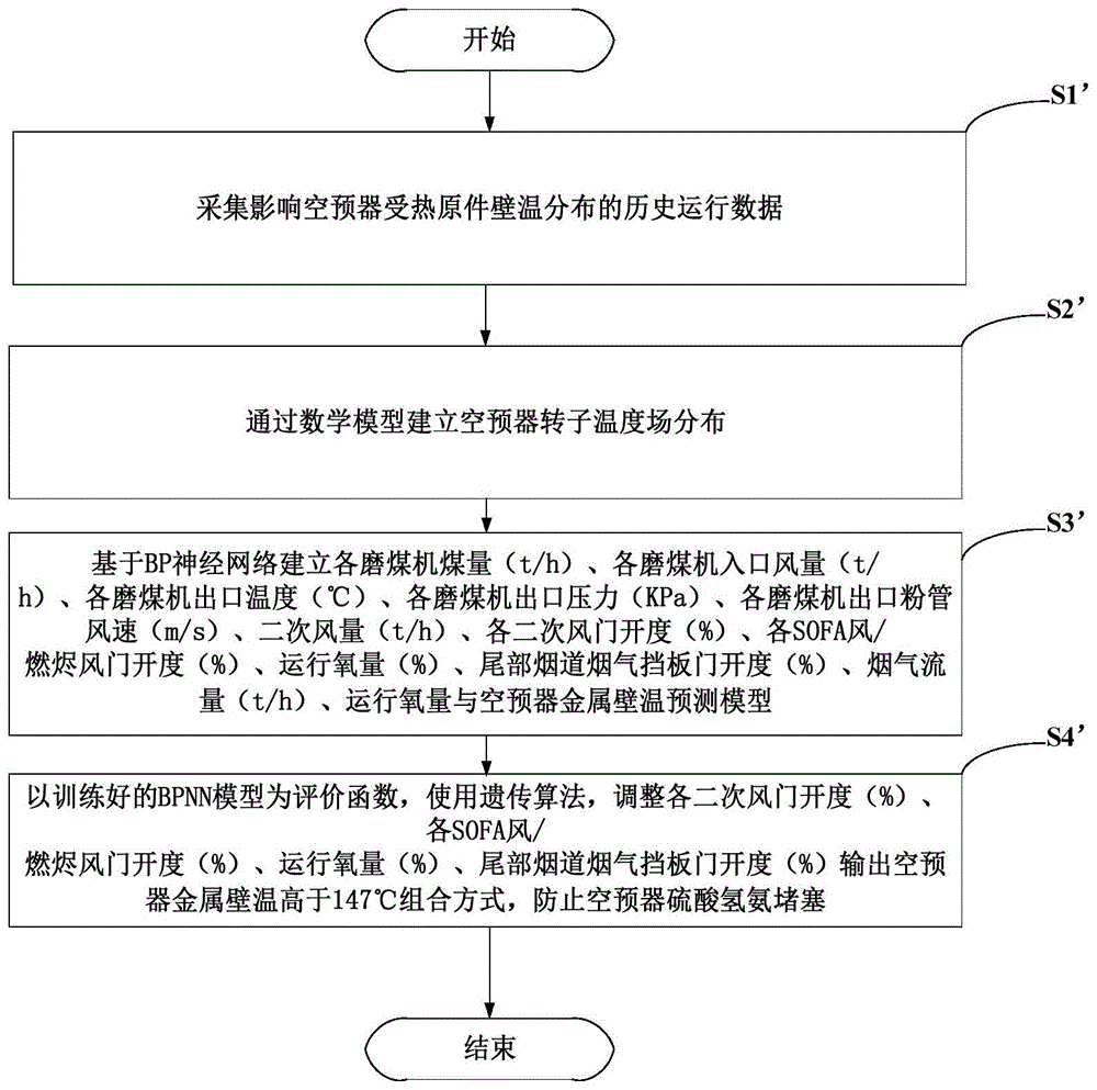
step S1': collecting historical operating data influencing the wall temperature distribution of heating elements of the air preheater, wherein in the embodiment, the historical operating data includes but is not limited to: coal quantity (t/h) of each coal mill, inlet air quantity (t/h) of each coal mill, outlet temperature (DEG C) of each coal mill, outlet pressure (KPa) of each coal mill, outlet powder pipe air speed (m/s) of each coal mill, secondary air quantity (t/h), opening (%) of each secondary air door, opening (%) of each SOFA air/burn-out air door, operating oxygen quantity (%), opening (%) of a tail flue gas baffle, flue gas flow (t/h), operating oxygen quantity, inlet and outlet primary of an air preheater, secondary air temperature (DEG C), inlet and outlet flue gas temperature (DEG C) of the air preheater and flue gas flow (t/h);
as shown in fig. 3, step S2': establishing the temperature field distribution of the air preheater rotor through a mathematical model, which comprises the following specific steps:
s21', constructing a primary air side mathematical model by using the following logics:
G fo C fo T fo =G fi C fi T fi -G fs C fi T fi -G fg C fi T fi +Q f (1)
wherein: g fo The flow rate of the primary air side outlet air is kg/h; c fo The specific heat capacity of air at the outlet of the primary air side is kJ/(kg DEG C); t is a unit of fo The primary air side outlet air temperature, DEG C; g fi The flow rate of the primary air side inlet air is kg/h; c fi The specific heat capacity of the inlet air at the primary air side is kJ/(kg DEG C); t is fi The primary air side inlet air temperature, DEG C; g fs The air leakage rate is kg/h from the primary air side to the secondary air side; g fg The air leakage flow rate of the primary air side to the smoke side is kg/h; q f The heat exchange energy of primary air side air and the heat storage element is kg/h.
Considering that primary wind temperature is a variation process, primary wind specific heat changes with temperature, and primary wind specific heat is a function of temperature:
C fo =C f (T fo ) (2)
C fi =C f (T fi ) (3)
according to the mass balance equation, the primary air side outlet air quantity is equal to the primary air side inlet air quantity minus the primary air side to secondary air side and flue gas side air leakage quantity:
G fo =G fi -G fs -G fg (4)
according to the assumed conditions, the direct air leakage is only calculated by neglecting the air leakage. The direct air leakage calculation formula is as follows:
in the formula: k is a radical of fs The air leakage coefficients of the primary air side and the secondary air side are obtained; k is a radical of fg The air leakage coefficients of the primary air side and the flue gas side are obtained; a. The fs Is the air leakage area of the primary air side and the secondary air side, m 2 ;A fg The air leakage area of the primary air side and the flue gas side, m 2 ;P f Primary air side pressure, KPa; p s Secondary air side pressure, KPa; p g Flue gas pressure, KPa, on the flue gas side; rho f Air density of primary air side in kg/m 3 (ii) a And Z is the number of layers of the sealing scraping blade.
In this formula, the air leakage coefficient k fs And k is fg The value is very important, and 1.4-1.8 is taken according to the characteristics of the rotary air preheater.
The direct air leakage area is characterized in that a deformation area formed due to the mushroom-shaped deformation of a rotor in a hot end radial air leakage gap is approximately a triangular area, and the calculation formula is as follows:
Δh=H 1 -H 2 (9)
wherein r is the radial actual sealing length of the air preheater rotor, m; delta h is the size of the deformation clearance of the rotor of the air preheater, m; h 1 The distance m is the distance between the sector plate and the end face of the rotor when the air preheater is in a cold state; h 2 The deformation m of the rotor in a relatively cold state when the air preheater is in a stable running state; delta t air preheater rotor cold and hot end difference, DEG C; h isThe height of the air preheater rotor, m; r is the radius of the rotor of the air preheater, and m is the radius of the rotor of the air preheater.
Heat exchange quantity Q of primary air side air and metal f Can be calculated by the heat transfer equation:
Q f =K f ·(T mf -T fa )·A f (11)
wherein K f Is the heat exchange coefficient of primary air side air and metal wall, W/m 2 ·K;T mf Primary air side metal temperature, deg.C; t is fa The average temperature of air at the primary air side is DEG C; a. The f Primary air side rotor heating area, m 2 。
The primary air side heat area can be calculated by the following formula:
wherein 0.9 takes into account that the heat storage material is not completely filled with the fluid; d n The inner diameter of the rotor of the air preheater is m; k is a radical of b In order to remove the proportion of the clapboard, the central cylinder and the like in the heat storage material; c x Area ratio m of heat storage material held per unit volume 2 /m 3 ;h x M is the actual height of the thermal storage material; m is f Is the fraction of the rotor covered by the primary wind (one for 15 °).
The solving method of the heat exchange coefficient comprises the following steps:
wherein λ is fa The heat conductivity coefficient of the air at the average temperature of primary air can be obtained by looking up a table, W/m.K; d f Is the primary wind side equivalent diameter, m; w is a f The air flow rate of the primary air side is m/s; v. of f The air viscosity coefficient under the average temperature of primary air can be obtained by looking up a table,W/m·K;P rf the air Plantt number is obtained by looking up a table under the average temperature of primary air. C i 、C l 、C H To correct the coefficient, take C i =1;C l Negligible, it may be taken as 1; c H The following table can be looked up in relation to the heat exchange element format
| Plate type
|
Thickness of plate/mm
|
For height/mm
|
Specific gravity/kg. M -3 |
C H |
Equivalent diameter/mm
|
| Flat plate
|
1.0
|
13.99
|
1301.63
|
0.9
|
10.06
|
| Corrugated plate and flat positioning plate
|
0.6
|
10.98
|
965.40
|
1.16
|
8.56
|
| Wave-shaped positioning plate
|
0.5
|
12.76
|
716.45
|
1.6
|
9.96 |
The primary air equivalent diameter is as follows:
wherein S f M is the primary air side air flow area 2 ;L f Is the total circumference of the primary wind side boundary, m 2 。
Primary air side air flow area S f The calculation formula is as follows:
k s the coefficient of the flow cross section occupied by the thermal storage material was taken to be 0.912.
Primary air side air flow velocity w f The calculation formula is as follows:
G fa the average flow of air at the primary air side is kg/h; rho f Is the primary air side air density in kg/m 3 。
The primary wind side resistance calculation formula is as follows:
wherein, F f Is the air fluid resistance of the primary air side, N; mu.s f Primary wind side friction coefficient; h is x The actual height m of the heat storage material in the air preheater; g is gravity acceleration, m/s 2 。
The total heat storage amount of the metal in a period of time is equal to the difference between the total heat transfer amount of the metal and the total heat release amount of the metal in the period of time, and a metal wall temperature equation is obtained:
wherein M is mf The mass of the metal on the primary air side is kg; c m Is the metal specific heat capacity, kJ/(kg ℃); m m The effective metal mass of the primary air side rotor is kg; n is the rotating speed of the air preheater rotor and rpm; q 1 The heat dissipation from the primary air side metal to the environment is kg/h.
Heat radiation Q of primary air side to environment 1 The following were used:
Q 1 =k 11 (T mf -T amb ) (21)
wherein k is 11 The heat dissipation coefficient of the primary air side metal is shown; t is amb Is at ambient temperature, DEG C. The primary air side metal wall temperature by euler discretization treatment was as follows:
wherein, T' mf The metal temperature on the windward side at the previous time (dt), deg.C.
S22', constructing a secondary air side mathematical model by using the following formula:
G so C so T so =G si C si T si +G fs C fi T fi -G sg C si T si +Q s (23)
wherein: g so Is a second orderThe air flow at the outlet of the air side is kg/h; c so The specific heat capacity of the air at the outlet of the secondary air side is kJ/(kg DEG C); t is so The secondary air side outlet air temperature, DEG C; g si The flow rate of the secondary air side inlet air is kg/h; c si The specific heat capacity of the inlet air at the secondary air side is kJ/(kg DEG C); t is si The temperature of the secondary air side inlet air is at DEG C; g fs The air leakage rate is kg/h from the primary air side to the secondary air side; g sg The air leakage flow rate of the secondary air side to the smoke side is kg/h; q s The heat exchange energy of the secondary air side air and the heat storage element is kg/h.
The equation of the direct air leakage rate of the secondary air direction on the smoke side is as follows:
in the formula: k is a radical of sg The secondary air side and the smoke side air leakage coefficients; a. The sg Is the air leakage area of the secondary air side and the smoke side, m 2 ;P s Secondary air side pressure, KPa; p g Flue gas pressure, KPa, on the flue gas side; rho s Secondary air side air density, kg/m 3 (ii) a And Z is the number of layers of the sealing scraping sheet.
Q s =K s ·(T ms -T sa )·A s (25)
Wherein K s The heat exchange coefficient of air at the secondary air side and the metal wall is W/m 2 ·K;T ms The metal temperature on the secondary air side is at DEG C; t is sa The average temperature of air at the secondary air side is DEG C; a. The s Secondary air side rotor heating area, m 2 。
The secondary air side heat area can be calculated by the following formula:
of these, 0.97 considers that the heat storage material is not completely filled with the fluid; d is a radical of n The inner diameter of the rotor of the air preheater is m; k is a radical of b In order to remove the proportion of the clapboard, the central cylinder and the like in the heat storage material; c x Area ratio m of heat storage material held per unit volume 2 /m 3 ;h x M is the actual height of the thermal storage material; m is s Is the fraction of the rotor covered by the secondary wind (one for 15 °).
The heat exchange coefficient of the secondary air is referred to (14), and the equation of the temperature of the metal wall on the secondary air side is as follows:
wherein, T' ms The metal temperature on the windward side at the previous time (dt), deg.C.
S23', constructing a smoke side mathematical model according to the following formula:
G go C go T go =G gi C gi T gi +G fg C fi T fi -G sg C si T si +Q s (29)
wherein: g go The flow rate of the flue gas at the outlet of the flue gas side is kg/h; c go The specific heat capacity of the flue gas at the outlet of the flue gas side is kJ/(kg ℃); t is go Flue gas side exit temperature, deg.C; g gi The flow rate of the flue gas at the inlet of the flue gas side is kg/h; c gi The specific heat capacity of the flue gas at the inlet of the flue gas side is kJ/(kg DEG C); t is gi The temperature of the flue gas at the inlet of the flue gas side is DEG C; g fg The air leakage rate of the primary air side to the smoke side is kg/h; g sg The air leakage flow rate of the secondary air side to the smoke side is kg/h; q g The heat exchange energy of the flue gas at the flue gas side and the heat storage element is kg/h.
Q g =K g ·(T mg -T ga )·A g (30)
Wherein K g Is the heat exchange coefficient between the flue gas side and the metal wall, W/m 2 ·K;T mg The metal temperature at the flue gas side is DEG C; t is a unit of ga Average temperature of flue gas side, DEG C; a. The g Side heating area of flue gas, m 2 。
The calculation formula of the metal wall temperature at the flue gas side is as follows:
wherein, T' mg The metal temperature on the windward side at the previous time (dt), deg.C.
Step S3': establishing a prediction model of coal quantity (t/h) of each coal mill, inlet air quantity (t/h) of each coal mill, outlet temperature (DEG C) of each coal mill, outlet pressure (KPa) of each coal mill, air speed (m/s) of a powder pipe at the outlet of each coal mill, secondary air quantity (t/h), opening (%) of each secondary air door, opening (%) of each SOFA air/burn-out air door, operating oxygen quantity (%), opening (%) of a flue gas baffle plate of a tail flue, flue gas flow (t/h), operating oxygen quantity and metal wall temperature of an air preheater based on a BP neural network:
using the collected historical data as the input of the BPNN model, using the minimum value of the metal wall temperature of the primary air side, the secondary air side and the smoke side obtained by calculation in the step ii as the prediction output, and establishing an input matrix x [1] =[N,M]Wherein N represents the number of samples, and M represents the number of input variables;
as shown in fig. 4, step S3' further includes the following specific steps:
s31', randomly initializing weight matrix w [1] =[M,q],b [1] =[1,q],a [1] =x [1] w [1] +b [1] Where q is the number of nodes of the first hidden layer, z [1] =sigmod(a [1] ) The sigmod function is as follows:
output z of the first hidden layer [1] As a second hidden layer input parameter, the hidden layers are f layers in total.
S32', obtaining the output z of the f hidden layer
[4] The output variable is 1 in z
[4] Repeating step ii as an input variable to calculate a predicted value of an output layer output target variable
And calculating the loss of the output vector and the actual value y of the target variable by using an L2 norm loss function, wherein the calculation formula is as follows:
s33', updating each hidden layer w according to the loss value S [i] 、b [i] ,
Wherein alpha is the hyper-parametric learning rate;
s34', through manual definition, after updating is completed, repeating the steps from S31' to S34' for n times, and calculating the minimum value of the wall temperature of the target variable air preheater
The root mean square error MSE of (a),
and predicting the minimum value of the metal wall temperature of the air preheater under different working conditions based on the trained BPNN.
Step S4': and (3) taking the trained BPNN model as an evaluation function, and using a genetic algorithm to adjust the opening (%) of each secondary air door, the opening (%) of each SOFA air/burn-out air door, the running oxygen content (%), and the opening (%) of a tail flue gas baffle plate to output a combined mode that the metal wall temperature of the air preheater is higher than 147 ℃ so as to prevent the blockage of the air preheater by the ammonium bisulfate:
as shown in fig. 5, step S4' further includes the following specific steps:
s41', setting the population size N, the crossing rate alpha, the variation rate beta and the iteration times T.
S42', randomly generating initial population by taking the opening (%) of each secondary air door, the opening (%) of each SOFA air/burn-out air door, the operating oxygen amount and the opening (%) of a tail flue gas baffle as optimization variables. In this embodiment, the random values of the air door and the smoke damper are in the range of 0-100, and the random value of the operating oxygen is in the range of 0-21.
And S43', taking the BPNN model trained in the step iii as an evaluation function, and enabling the output value of the evaluation function to be larger than 147 ℃ as a satisfied condition.
S44', number of initial iterations t =1, and N individuals x are randomly generated i I =1,2,3.., N, in this example, each individual is a combination of operating conditions of length M, representing a test protocol.
S45', calculating an output value of the current population evaluation function, and judging that the output value is greater than the 147 ℃ population.
S46', the current population is selected, crossed and mutated to generate the next generation population.
S47', repeating the steps S44' to S46' until the iteration number T, outputting a final scheme, and adjusting the air door, the baffle door and the oxygen amount to ensure that the temperature of the metal wall surface of the air preheater is higher than 147 ℃ and prevent the air preheater from being blocked due to the deposition of ammonium bisulfate.
In conclusion, the mathematical model of the invention establishes the temperature field distribution of the rotor of the air preheater, and adopts a BPNN network to establish a regression model of historical operation data and the temperature field wall temperature distribution of the rotor of the air preheater. The temperature of the rotor of the air preheater is controlled in real time, the air preheater is prevented from being blocked, and the anti-blocking effect of the air preheater is improved.
According to the invention, the metal wall temperature of the rotary air preheater is ensured to be higher than the condensation temperature of ammonium bisulfate by controlling the operation parameters of the boiler, so that the metal wall temperature of the rotary air preheater is optimally controlled, and the blockage of the rotary air preheater caused by the ammonium bisulfate is prevented. The cost generated by additionally arranging the water spraying and guiding device in the prior art is avoided. Meanwhile, the risk that a physical anti-blocking device in the prior art breaks down due to the internal environment of the air preheater is avoided, and the reliability of the system is improved.
According to the method, the trained BPNN model is used as an evaluation function, a genetic algorithm is used, the opening of each secondary air door, the opening of each SOFA air/burnout air door, the running oxygen amount and the opening of a tail flue gas baffle are adjusted according to the minimum wall temperature of the air preheater under different working conditions, and the metal wall temperature of the output air preheater is higher than 147 ℃, so that the blockage of the air preheater by ammonium bisulfate is prevented, and the control precision of the anti-blockage operation of the air preheater is improved. The invention solves the technical problems of poor blockage prevention effect and high use cost of the air preheater in the prior art.
The above examples are only intended to illustrate the technical solution of the present invention, but not to limit it; although the present invention has been described in detail with reference to the foregoing embodiments, it will be understood by those of ordinary skill in the art that: the technical solutions described in the foregoing embodiments may still be modified, or some technical features may be equivalently replaced; and such modifications or substitutions do not depart from the spirit and scope of the corresponding technical solutions of the embodiments of the present invention.