CN115973473B - Unmanned aerial vehicle survey and drawing data acquisition device - Google Patents
Unmanned aerial vehicle survey and drawing data acquisition device Download PDFInfo
- Publication number
- CN115973473B CN115973473B CN202310278277.XA CN202310278277A CN115973473B CN 115973473 B CN115973473 B CN 115973473B CN 202310278277 A CN202310278277 A CN 202310278277A CN 115973473 B CN115973473 B CN 115973473B
- Authority
- CN
- China
- Prior art keywords
- fixedly connected
- frame
- groove
- slot
- fixed
- Prior art date
- Legal status (The legal status is an assumption and is not a legal conclusion. Google has not performed a legal analysis and makes no representation as to the accuracy of the status listed.)
- Expired - Fee Related
Links
Images

Classifications
-
- Y—GENERAL TAGGING OF NEW TECHNOLOGICAL DEVELOPMENTS; GENERAL TAGGING OF CROSS-SECTIONAL TECHNOLOGIES SPANNING OVER SEVERAL SECTIONS OF THE IPC; TECHNICAL SUBJECTS COVERED BY FORMER USPC CROSS-REFERENCE ART COLLECTIONS [XRACs] AND DIGESTS
- Y02—TECHNOLOGIES OR APPLICATIONS FOR MITIGATION OR ADAPTATION AGAINST CLIMATE CHANGE
- Y02T—CLIMATE CHANGE MITIGATION TECHNOLOGIES RELATED TO TRANSPORTATION
- Y02T50/00—Aeronautics or air transport
- Y02T50/40—Weight reduction
Landscapes
- Fittings On The Vehicle Exterior For Carrying Loads, And Devices For Holding Or Mounting Articles (AREA)
Abstract
Description
技术领域technical field
本发明涉及无人机测绘技术领域,具体涉及一种无人机测绘数据采集装置。The invention relates to the technical field of unmanned aerial vehicle surveying and mapping, in particular to a data acquisition device for unmanned aerial vehicle surveying and mapping.
背景技术Background technique
经济的快速发展促使了人们对于工程测绘质量提出了更高的要求,推动着相关技术的改革和创新,无人机遥感测绘在此背景之下应运而生。作为一种新型测试技术,无人机遥感测绘有着其他手段所无法比拟的优势,涉及了多个层面的内容,对于提高测绘工作的精度和效率都有表现出了很明显的优势,研究无人机遥感测绘技术在工程测绘中的应用的相关问题,对于促进无人机遥感测绘技术更快更好地发展有十分重要的现实意义。The rapid development of the economy has prompted people to put forward higher requirements for the quality of engineering surveying and mapping, and promote the reform and innovation of related technologies. Under this background, UAV remote sensing surveying and mapping came into being. As a new type of testing technology, UAV remote sensing surveying and mapping has advantages unmatched by other means, involving multiple levels of content, and has shown obvious advantages in improving the accuracy and efficiency of surveying and mapping work. Problems related to the application of UAV remote sensing mapping technology in engineering surveying and mapping have very important practical significance for promoting the faster and better development of UAV remote sensing mapping technology.
公开号为CN214383415U的发明公开了一种无人机测绘数据采集装置,其通过设置伺服电机和转轴,可以带动摄像设备旋转,对摄像设备的角度进行调节,通过设置定位块、通槽、推板、第一压簧、限位杆和限位孔,可以方便拆卸摄像设备,给摄像设备进行充电和拷贝数据,通过设置以上结构,具备方便对相机进行拆卸的优点,解决了现有的无人机其摄像机大多都是固定安装在机架上,不方便将相机拆卸下来,给充电和拷贝相机内的数据带来不便的问题;但是,此装置结构在实际使用过程中仍然有一些不足之处,在调整摄像角度方面,其只能进行平行角度上的调整,实际使用时仍有一定的限制性,且虽然能够方便对相机进行拆卸,但确实直接将其安装在外部进行数据测绘,很容易导致摄像设备在拍摄过程中受损受潮。The invention with the publication number CN214383415U discloses a UAV surveying and mapping data acquisition device, which can drive the camera equipment to rotate by setting a servo motor and a rotating shaft, and adjust the angle of the camera equipment. , the first compression spring, the limit rod and the limit hole can conveniently disassemble the camera equipment, charge the camera equipment and copy data. Most of the cameras of the machine are fixedly installed on the rack, which is inconvenient to disassemble the camera, which brings inconvenience to charging and copying the data in the camera; however, the structure of this device still has some shortcomings in the actual use process. , in terms of adjusting the camera angle, it can only adjust the parallel angle, and there are still some restrictions in actual use, and although the camera can be easily disassembled, it is indeed easy to install it directly outside for data surveying and mapping. As a result, the camera equipment was damaged and damp during the shooting process.
发明内容Contents of the invention
本发明的目的在于提供一种无人机测绘数据采集装置,解决以上技术问题。The object of the present invention is to provide a UAV surveying and mapping data acquisition device to solve the above technical problems.
本发明的目的可以通过以下技术方案实现:The purpose of the present invention can be achieved through the following technical solutions:
一种无人机测绘数据采集装置,包括定位板,所述定位板的底端固定连接有顶盖,所述顶盖的底端固定连接有连接座,所述连接座的底端表面焊接固定有连接柱;An unmanned aerial vehicle surveying and mapping data acquisition device, comprising a positioning plate, the bottom end of the positioning plate is fixedly connected with a top cover, the bottom end of the top cover is fixedly connected with a connecting seat, and the bottom surface of the connecting seat is welded and fixed There are connecting columns;
所述定位板的底端表面焊接固定有连接架,所述连接架的表面设有开槽,所述开槽的内侧靠近顶端设有限位槽,所述开槽内部的顶端表面固定连接有弹簧,所述弹簧的底端表面固定连接有橡胶垫,所述开槽内部的底端表面固定连接有乳胶垫,所述开槽的表面嵌入连接有嵌块,所述嵌块的外侧表面套设连接有套架。The bottom surface of the positioning plate is welded and fixed with a connecting frame, the surface of the connecting frame is provided with a slot, the inner side of the slot is provided with a limit slot near the top, and the top surface inside the slot is fixedly connected with a spring , the bottom surface of the spring is fixedly connected with a rubber pad, the bottom surface inside the slot is fixedly connected with a latex pad, the surface of the slot is embedded and connected with an inlay block, and the outer surface of the inlay block is sleeved Connected with a rack.
优选的,所述嵌块的表面设有贯通孔,所述套架的内侧表面位于顶端处设有嵌槽,所述套架的侧表面位于嵌槽处设有连通孔,所述套架的底端表面焊接固定有底连接板,所述定位板的顶端表面固定连接有无人机。Preferably, the surface of the insert is provided with a through hole, the inner surface of the sleeve frame is provided with a slot at the top end, and the side surface of the sleeve frame is provided with a communication hole at the slot, and the sleeve frame The bottom surface is welded and fixed with a bottom connecting plate, and the top surface of the positioning plate is fixedly connected with a drone.
优选的,所述顶盖的顶端表面设有组装槽,所述顶盖的底端表面固定连接有安装盒,所述顶盖的底端表面固定安装有套座,所述套座的数量设置为三个,两个所述套座的表面转动连接有连杆,另一个所述套座的表面固定安装有联动马达,所述连杆的表面和联动马达的输出端卡接有连接齿轮,所述连杆的表面夹持固定有联动臂。Preferably, an assembly groove is provided on the top surface of the top cover, an installation box is fixedly connected to the bottom surface of the top cover, sleeves are fixedly installed on the bottom surface of the top cover, and the number of the sleeves is set There are three, the surfaces of the two sockets are rotatably connected with connecting rods, the surface of the other socket is fixedly mounted with a linkage motor, and the surface of the connecting rods is clamped with the output end of the linkage motor with a connecting gear. A linkage arm is clamped and fixed on the surface of the connecting rod.
优选的,所述联动臂的底端表面焊接固定有转架,所述转架的弧形表面固定连接有螺纹架,所述转架的两端焊接固定有半弧形架,所述半弧形架的表面设有活动槽,所述半弧形架的底端表面滑动连接有包覆架。Preferably, the bottom surface of the linkage arm is welded and fixed with a turntable, the arc surface of the turntable is fixedly connected with a threaded frame, the two ends of the turntable are welded and fixed with a semi-arc frame, and the half-arc The surface of the shaped frame is provided with movable grooves, and the bottom surface of the semi-arc frame is slidably connected with a covering frame.
优选的,所述包覆架的顶端位于两短侧边处固定连接有防脱块,所述包覆架的表面位于长侧边处固定安装有套块,所述套块的表面转动连接有丝杆,所述套块的表面固定安装有驱动马达,所述驱动马达的输出端与丝杆固定连接,所述包覆架的底端表面固定安装有凸块,所述凸块的侧表面设有卡块,所述凸块的侧表面与卡块相对位置处设有螺孔。Preferably, the top of the covering frame is fixedly connected with anti-off blocks at the two short sides, the surface of the covering frame is fixedly installed at the long sides, and the surface of the covering frame is rotatably connected with Screw rod, the surface of the cover block is fixedly installed with a drive motor, the output end of the drive motor is fixedly connected with the screw rod, the bottom surface of the covering frame is fixedly installed with a bump, and the side surface of the bump A clamping block is provided, and a screw hole is provided at a position opposite to the clamping block on the side surface of the protrusion.
优选的,所述连接座的顶端表面设有凹槽,所述凹槽的表面设有卡槽,所述凹槽的表面与卡槽相对位置处设有开孔,所述凸块和凹槽卡接,所述连接座的底端表面固定连接有连接柱。Preferably, the top surface of the connecting seat is provided with a groove, the surface of the groove is provided with a card slot, and the surface of the groove is provided with an opening at a position opposite to the card slot, and the protrusion and the groove snap connection, the bottom surface of the connection seat is fixedly connected with the connection column.
优选的,所述连接柱的底端表面焊接固定有连接臂,所述连接臂的内侧设有延伸槽,所述连接臂的底端表面固定连接有齿轮盘,所述连接臂的侧表面固定连接有连接盘,所述连接盘的内部固定安装有驱动器,所述驱动器的输出端固定安装有传动齿轮,所述齿轮盘的表面设有轨迹槽,所述轨迹槽的内部设有对接杆,所述对接杆的底端表面固定连接有防脱节,所述对接杆的顶端表面固定连接有延伸杆,所述延伸杆表面焊接固定有撑架,所述撑架的表面卡接有透明罩,所述透明罩的内侧靠近顶端处设有撑槽。Preferably, the bottom surface of the connecting column is welded and fixed with a connecting arm, the inner side of the connecting arm is provided with an extension groove, the bottom surface of the connecting arm is fixedly connected with a gear plate, and the side surface of the connecting arm is fixed A connection plate is connected, a driver is fixedly installed inside the connection plate, a transmission gear is fixedly installed at the output end of the driver, a track groove is provided on the surface of the gear plate, and a docking rod is provided inside the track groove, The bottom surface of the docking rod is fixedly connected with an anti-disconnection, the top surface of the docking rod is fixedly connected with an extension rod, the surface of the extension rod is welded and fixed with a bracket, and the surface of the bracket is clamped with a transparent cover, A supporting groove is provided on the inner side of the transparent cover near the top end.
本发明的有益效果:Beneficial effects of the present invention:
通过设置的定位板组件结构,当连接架和套架两连接主体通过嵌块固定之后,在无人机测绘过程中,一旦遇到震动,嵌块顶部将与橡胶垫触碰,利用弹簧起到缓震的效果;Through the set positioning plate assembly structure, when the two connecting bodies of the connecting frame and the sleeve frame are fixed by the insert, in the process of UAV surveying and mapping, once the vibration is encountered, the top of the insert will touch the rubber pad, and the spring will play a role. cushioning effect;
通过顶盖内部的联动臂配合其底部的转架能够有效提升摄像设备的拍摄角度范围;Through the linkage arm inside the top cover and the swivel frame at the bottom, the shooting angle range of the camera equipment can be effectively improved;
通过利用连接柱组件结构,配合延伸杆对撑架的内外联动,可使其从内部卡住透明罩,从而方便维修更换摄像设备。By using the structure of the connecting column assembly and cooperating with the internal and external linkage of the extension rod to the support frame, the transparent cover can be clamped from the inside, thereby facilitating the maintenance and replacement of the camera equipment.
附图说明Description of drawings
下面结合附图对本发明作进一步的说明。The present invention will be further described below in conjunction with the accompanying drawings.
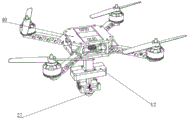
图1是本发明整体结构示意图;Fig. 1 is a schematic diagram of the overall structure of the present invention;
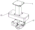
图2是本发明测绘数据采集设备结构示意图;Fig. 2 is a schematic structural diagram of surveying and mapping data acquisition equipment of the present invention;
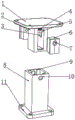
图3是本发明定位板组件拆分结构示意图;Fig. 3 is a schematic diagram of the disassembled structure of the positioning plate assembly of the present invention;
图4是本发明顶盖组件拆分结构示意图;Fig. 4 is a schematic diagram of the disassembled structure of the top cover assembly of the present invention;
图5是本发明的连接座和连接柱组件拆分结构示意图;Fig. 5 is a schematic diagram of the disassembled structure of the connecting seat and connecting column assembly of the present invention;
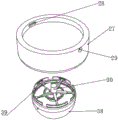
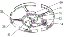
图6是本发明连接柱组件结构示意图。Fig. 6 is a schematic diagram of the structure of the connecting column assembly of the present invention.
图中:1、定位板;2、连接架;3、限位槽;4、弹簧;5、橡胶垫;6、嵌块;7、贯通孔;8、套架;9、嵌槽;10、连通孔;11、底连接板;12、顶盖;13、安装盒;14、套座;15、连杆;16、联动马达;17、联动臂;18、转架;19、螺纹架;20、半弧形架;21、活动槽;22、包覆架;23、防脱块;24、套块;25、丝杆;26、驱动马达;27、连接座;28、卡槽;29、开孔;30、连接柱;31、连接臂;32、齿轮盘;33、连接盘;34、传动齿轮;35、防脱节;36、延伸杆;37、撑架;38、透明罩;39、撑槽;40、无人机。In the figure: 1. Positioning plate; 2. Connecting frame; 3. Limiting groove; 4. Spring; 5. Rubber pad; 6. Insert block; 7. Through hole; Connecting hole; 11, bottom connecting plate; 12, top cover; 13, installation box; 14, sleeve seat; 15, connecting rod; 16, linkage motor; 17, linkage arm; 18, turn frame; 19, thread frame; , semi-arc frame; 21, movable groove; 22, cladding frame; 23, anti-off block; 24, sleeve block; 25, screw rod; 26, drive motor; 27, connecting seat; Opening; 30, connecting column; 31, connecting arm; 32, gear plate; 33, connecting plate; 34, transmission gear; 35, anti-disconnection; 36, extension rod; Support slot; 40, unmanned aerial vehicle.
具体实施方式Detailed ways
下面将结合本发明实施例中的附图,对本发明实施例中的技术方案进行清楚、完整地描述,显然,所描述的实施例仅仅是本发明一部分实施例,而不是全部的实施例。基于本发明中的实施例,本领域普通技术人员在没有作出创造性劳动前提下所获得的所有其它实施例,都属于本发明保护的范围。The following will clearly and completely describe the technical solutions in the embodiments of the present invention with reference to the accompanying drawings in the embodiments of the present invention. Obviously, the described embodiments are only some, not all, embodiments of the present invention. Based on the embodiments of the present invention, all other embodiments obtained by persons of ordinary skill in the art without creative efforts fall within the protection scope of the present invention.
请参阅图1-6所示,本发明为一种无人机测绘数据采集装置,包括定位板1,定位板1的底端固定连接有顶盖12,顶盖12的底端固定连接有连接座27,连接座27的底端表面焊接固定有连接柱30;Please refer to shown in Fig. 1-6, the present invention is a kind of unmanned aerial vehicle surveying and mapping data acquisition device, comprises
定位板1的底端表面焊接固定有连接架2,连接架2的表面设有开槽,开槽的内侧靠近顶端设有限位槽3,开槽内部的顶端表面固定连接有弹簧4,弹簧4的底端表面固定连接有橡胶垫5,开槽内部的底端表面固定连接有乳胶垫,开槽的表面嵌入连接有嵌块6,嵌块6的外侧表面套设连接有套架8,在此无人机测绘数据采集装置运作过程中,其在遇到气流等情况时,不可避免地会遇到气流等会引起震动的情况,与无人机连接的定位板1在将震动通过连接架2传递到套架的过程中,每当嵌块6因惯性与橡胶垫5接触时,弹簧4将收到压缩,从而可以起到一定的缓震效果,而当重力平衡之后,压靠在乳胶垫表面,也能缓冲一定的震动;The bottom surface of the
嵌块6的表面设有贯通孔7,套架8的内侧表面位于顶端处设有嵌槽9,套架8的侧表面位于嵌槽9处设有连通孔10,套架8的底端表面焊接固定有底连接板11,定位板1的顶端表面固定连接有无人机40,在连接架2和套架8进行组装连接时,可先将两组嵌块6由两侧往连接架2表面并拢,然后将套架8由下往上移动,使得嵌块6插入嵌槽9中,并使贯通孔7与连通孔10对接,此时可完成对接;The surface of the
顶盖12的顶端表面设有组装槽,顶盖12的底端表面固定连接有安装盒13,顶盖12的底端表面固定安装有套座14,套座14的数量设置为三个,两个套座14的表面转动连接有连杆15,另一个套座14的表面固定安装有联动马达16,连杆15的表面和联动马达16的输出端卡接有连接齿轮,连杆15的表面夹持固定有联动臂17,当需要使摄像设备朝着一平行轴进行调整方向时,可启动联动马达16,使得连接齿轮的联动作用下,位于套座14表面的连杆15能够朝指定时针方向转动,并带动联动臂17进行转动;The top surface of the
联动臂17的底端表面焊接固定有转架18,转架18的弧形表面固定连接有螺纹架19,转架18的两端焊接固定有半弧形架20,半弧形架20的表面设有活动槽21,半弧形架20的底端表面滑动连接有包覆架22,当需要使摄像设备朝另一平行轴方向调整方向时,可使得丝杆25配合螺纹架19进行转动,过程中,位于转架18两端的半弧形架20将配合包覆架22表面的弧度进行转动,并在防脱块23和活动槽21的作用下保持运动稳定;The bottom surface of the
包覆架22的顶端位于两短侧边处固定连接有防脱块23,包覆架22的表面位于长侧边处固定安装有套块24,套块24的表面转动连接有丝杆25,套块24的表面固定安装有驱动马达26,驱动马达26的输出端与丝杆25固定连接,包覆架22的底端表面固定安装有凸块,凸块的侧表面设有卡块,凸块的侧表面与卡块相对位置处设有螺孔,驱动丝杆25转动时,可电控启动驱动马达26,然后使得丝杆25配合其输出端朝指定方向转动;The top of the
连接座27的顶端表面设有凹槽,凹槽的表面设有卡槽28,凹槽的表面与卡槽28相对位置处设有开孔29,凸块和凹槽卡接,连接座27的底端表面固定连接有连接柱30,拆装连接座27时,也只需要使得连接座27表面的卡槽28先与卡块对接,然后等螺孔与开孔29对其之后,便可以使用螺栓进行固定;The top surface of the connecting
连接柱30的底端表面焊接固定有连接臂31,连接臂31的内侧设有延伸槽,连接臂31的底端表面固定连接有齿轮盘32,连接臂31的侧表面固定连接有连接盘33,连接盘33的内部固定安装有驱动器,驱动器的输出端固定安装有传动齿轮34,齿轮盘32的表面设有轨迹槽,轨迹槽的内部设有对接杆,对接杆的底端表面固定连接有防脱节35,对接杆的顶端表面固定连接有延伸杆36,延伸杆36表面焊接固定有撑架37,撑架37的表面卡接有透明罩38,透明罩38的内侧靠近顶端处设有撑槽39,等摄像设备安装进透明罩38中之后,可电控启动连接盘33中的驱动器,然后使传动齿轮34带动齿轮盘32转动,过程中,对接杆也将在轨迹槽的限制作用下向外移动,同时与其连接的延伸杆36也将从连接臂31中伸出,焊接在其表面的撑架37也将抵靠在透明罩38的撑槽39中,从而完成对其的锁定,操作简单方便,可快速拆装摄像头,节省时间。The bottom surface of the connecting
本发明的工作原理:等摄像设备安装进透明罩38中之后,可电控启动连接盘33中的驱动器,然后使传动齿轮34带动齿轮盘32转动,过程中,对接杆也将在轨迹槽的限制作用下向外移动,同时与其连接的延伸杆36也将从连接臂31中伸出,焊接在其表面的撑架37也将抵靠在透明罩38的撑槽39中,从而完成对其的锁定,操作简单方便,可快速拆装摄像头,节省时间,在无人机测绘数据采集过程中,当需要使摄像设备朝着一平行轴进行调整方向时,可启动联动马达16,使得连接齿轮的联动作用下,位于套座14表面的连杆15能够朝指定时针方向转动,并带动联动臂17进行转动,当需要使摄像设备朝另一平行轴方向调整方向时,可使得丝杆25配合螺纹架19进行转动,过程中,位于转架18两端的半弧形架20将配合包覆架22表面的弧度进行转动,并在防脱块23和活动槽21的作用下保持运动稳定,而在其在遇到气流等情况时,不可避免地会遇到气流等会引起震动的情况,与无人机连接的定位板1在将震动通过连接架2传递到套架的过程中,每当嵌块6因惯性与橡胶垫5接触时,弹簧4将收到压缩,从而可以起到一定的缓震效果,而当重力平衡之后,压靠在乳胶垫表面,也能缓冲一定的震动。Working principle of the present invention: After the camera equipment is installed in the
以上对本发明的一个实施例进行了详细说明,但内容仅为本发明的较佳实施例,不能被认为用于限定本发明的实施范围。凡依本发明申请范围所作的均等变化与改进等,均应仍归属于本发明的专利涵盖范围之内。An embodiment of the present invention has been described in detail above, but the content is only a preferred embodiment of the present invention, and cannot be considered as limiting the implementation scope of the present invention. All equivalent changes and improvements made according to the application scope of the present invention shall still belong to the scope covered by the patent of the present invention.
Claims (4)
Priority Applications (1)
| Application Number | Priority Date | Filing Date | Title |
|---|---|---|---|
| CN202310278277.XA CN115973473B (en) | 2023-03-21 | 2023-03-21 | Unmanned aerial vehicle survey and drawing data acquisition device |
Applications Claiming Priority (1)
| Application Number | Priority Date | Filing Date | Title |
|---|---|---|---|
| CN202310278277.XA CN115973473B (en) | 2023-03-21 | 2023-03-21 | Unmanned aerial vehicle survey and drawing data acquisition device |
Publications (2)
| Publication Number | Publication Date |
|---|---|
| CN115973473A CN115973473A (en) | 2023-04-18 |
| CN115973473B true CN115973473B (en) | 2023-06-27 |
Family
ID=85976529
Family Applications (1)
| Application Number | Title | Priority Date | Filing Date |
|---|---|---|---|
| CN202310278277.XA Expired - Fee Related CN115973473B (en) | 2023-03-21 | 2023-03-21 | Unmanned aerial vehicle survey and drawing data acquisition device |
Country Status (1)
| Country | Link |
|---|---|
| CN (1) | CN115973473B (en) |
Citations (2)
| Publication number | Priority date | Publication date | Assignee | Title |
|---|---|---|---|---|
| CN207991529U (en) * | 2017-05-27 | 2018-10-19 | 广西万维空间科技有限公司 | A kind of unmanned plane surveying and mapping data harvester |
| CN212829121U (en) * | 2020-09-17 | 2021-03-30 | 周晓东 | Data acquisition equipment for channel surveying and mapping |
Family Cites Families (6)
| Publication number | Priority date | Publication date | Assignee | Title |
|---|---|---|---|---|
| WO2017128051A1 (en) * | 2016-01-26 | 2017-08-03 | 深圳市大疆灵眸科技有限公司 | Pan-tilt, unmanned aerial vehicle, photographing device, and movable device |
| KR101942832B1 (en) * | 2018-10-19 | 2019-01-30 | (주)뉴비전네트웍스 | Spatial image compensation system for various data editing |
| EP3942246A4 (en) * | 2019-03-18 | 2023-03-08 | Daniel Baumgartner | Drone-assisted systems and methods of calculating a ballistic solution for a projectile |
| CN214383415U (en) * | 2021-03-19 | 2021-10-12 | 信小伟 | Unmanned aerial vehicle survey and drawing data acquisition device |
| CN114261527A (en) * | 2022-01-07 | 2022-04-01 | 闫丽丽 | Intelligent unmanned aerial vehicle mapping system |
| CN115806068A (en) * | 2022-12-01 | 2023-03-17 | 江苏城建校建筑规划设计院有限公司 | City is updated with survey and drawing unmanned aerial vehicle device |
-
2023
- 2023-03-21 CN CN202310278277.XA patent/CN115973473B/en not_active Expired - Fee Related
Patent Citations (2)
| Publication number | Priority date | Publication date | Assignee | Title |
|---|---|---|---|---|
| CN207991529U (en) * | 2017-05-27 | 2018-10-19 | 广西万维空间科技有限公司 | A kind of unmanned plane surveying and mapping data harvester |
| CN212829121U (en) * | 2020-09-17 | 2021-03-30 | 周晓东 | Data acquisition equipment for channel surveying and mapping |
Also Published As
| Publication number | Publication date |
|---|---|
| CN115973473A (en) | 2023-04-18 |
Similar Documents
| Publication | Publication Date | Title |
|---|---|---|
| CN211136631U (en) | Automobile parts processing is with mechanical arm that polishes | |
| CN115973473B (en) | Unmanned aerial vehicle survey and drawing data acquisition device | |
| CN116276488A (en) | A lithium battery shell processing equipment | |
| CN219599325U (en) | Positioning and clamping device for processing automobile outer rearview mirror | |
| CN111913844A (en) | Computer hardware testing platform convenient to adjust | |
| CN111828791A (en) | A multimedia projection digital all-in-one machine | |
| CN221056013U (en) | Impact test fixture | |
| CN209102977U (en) | Multi-core fiber multi-function fixture | |
| CN208432825U (en) | A kind of pre- pressure actuator of accurate rotation contraposition of bonding machines | |
| CN218057375U (en) | Automatic mud base pile up neatly device of robot | |
| CN105681785A (en) | Anti-shake test device for camera module and test method thereof | |
| CN216313102U (en) | Two-dimensional direct-drive tracking mechanism based on quantum communication | |
| CN221665707U (en) | Angle regulation type intelligent cloth ball control machine | |
| CN222914096U (en) | A controller detection device | |
| CN222393694U (en) | Torque detection mechanism | |
| CN210879046U (en) | Automatic grinding device of outer lane roller slot | |
| CN209385945U (en) | Image modalities | |
| CN114425754A (en) | A stable encoder and its component parts assembly tooling table | |
| CN209598966U (en) | A grinding wheel modification device for a screw | |
| CN220718733U (en) | Burr removing device for battery cell shell | |
| CN221135938U (en) | Robot vision letter sorting camera | |
| CN223035448U (en) | Double-station lens coupling machine | |
| CN220806726U (en) | Foundry goods grinding device | |
| CN111752343A (en) | Computer software and hardware detection device convenient to remove and adjust | |
| CN221849665U (en) | Polishing equipment for lenses |
Legal Events
| Date | Code | Title | Description |
|---|---|---|---|
| PB01 | Publication | ||
| PB01 | Publication | ||
| SE01 | Entry into force of request for substantive examination | ||
| SE01 | Entry into force of request for substantive examination | ||
| GR01 | Patent grant | ||
| GR01 | Patent grant | ||
| CF01 | Termination of patent right due to non-payment of annual fee | ||
| CF01 | Termination of patent right due to non-payment of annual fee |
Granted publication date: 20230627 |