CN115991402A - A self-adhesive trademark die-cutting machine - Google Patents
A self-adhesive trademark die-cutting machine Download PDFInfo
- Publication number
- CN115991402A CN115991402A CN202310094679.4A CN202310094679A CN115991402A CN 115991402 A CN115991402 A CN 115991402A CN 202310094679 A CN202310094679 A CN 202310094679A CN 115991402 A CN115991402 A CN 115991402A
- Authority
- CN
- China
- Prior art keywords
- self
- die
- fixedly connected
- driving
- cutting machine
- Prior art date
- Legal status (The legal status is an assumption and is not a legal conclusion. Google has not performed a legal analysis and makes no representation as to the accuracy of the status listed.)
- Withdrawn
Links
Images




Classifications
-
- Y—GENERAL TAGGING OF NEW TECHNOLOGICAL DEVELOPMENTS; GENERAL TAGGING OF CROSS-SECTIONAL TECHNOLOGIES SPANNING OVER SEVERAL SECTIONS OF THE IPC; TECHNICAL SUBJECTS COVERED BY FORMER USPC CROSS-REFERENCE ART COLLECTIONS [XRACs] AND DIGESTS
- Y02—TECHNOLOGIES OR APPLICATIONS FOR MITIGATION OR ADAPTATION AGAINST CLIMATE CHANGE
- Y02P—CLIMATE CHANGE MITIGATION TECHNOLOGIES IN THE PRODUCTION OR PROCESSING OF GOODS
- Y02P70/00—Climate change mitigation technologies in the production process for final industrial or consumer products
- Y02P70/10—Greenhouse gas [GHG] capture, material saving, heat recovery or other energy efficient measures, e.g. motor control, characterised by manufacturing processes, e.g. for rolling metal or metal working
Landscapes
- Perforating, Stamping-Out Or Severing By Means Other Than Cutting (AREA)
Abstract
Description
技术领域technical field
本发明涉及模切机的技术领域,尤其是涉及一种不干胶商标模切机。The invention relates to the technical field of die-cutting machines, in particular to a self-adhesive trademark die-cutting machine.
背景技术Background technique
不干胶商标以纸张、薄膜等材料为面料,背面涂有胶粘剂,以涂硅保护纸为底纸的一种复合材料,经印刷、模切等工序后成为成品商标,常用于产品外包装上。不干胶商标模切机又称数控模切机,可以自动完成不干胶商标的模切和收废工作,十分方便。Self-adhesive trademarks are made of paper, film and other materials, with adhesive on the back and silicon-coated protective paper as a composite material. After printing, die-cutting and other processes, they become finished trademarks and are often used on product packaging. . Self-adhesive label die-cutting machine, also known as CNC die-cutting machine, can automatically complete the die-cutting and waste collection of self-adhesive labels, which is very convenient.
相关技术中,公开了一种自动高速不干胶商标模切机及模切工艺,模切机包括机架,在机架上设置有放料机构、牵引机构、模切机构以及收卷机构;模切机构包括上模板、下模板,上模板与下模板之间通过导向机构连接,在上模板与下模板之间还设置有缓冲机构,在上模板的下端设置有刀模板,在上模板的下端设置插块,在刀模板上设有插槽,刀模板可通过插槽卡入到插块上,并锁紧。工艺包括放料、模切、主料废料分离以及收卷。In the related art, an automatic high-speed self-adhesive trademark die-cutting machine and die-cutting process are disclosed. The die-cutting machine includes a frame, and a feeding mechanism, a traction mechanism, a die-cutting mechanism and a winding mechanism are arranged on the frame; The die-cutting mechanism includes an upper template and a lower template. The upper template and the lower template are connected by a guide mechanism. There is also a buffer mechanism between the upper template and the lower template. The lower end is provided with an insert block, and a slot is arranged on the knife template, and the knife template can be inserted into the insert block through the slot and locked. The process includes unwinding, die cutting, main material waste separation and winding.
针对上述中的相关技术,发明人认为在收卷成品商标的过程中,缠绕在收卷机构上的成品商标的厚度会不断增加,因此,收卷同等长度的成品商标时收卷机构需要转动的角度在不断改变,如果收卷机构转动的角度过大或过小,均会导致收卷工作出现错误,干扰模切机正常工作。In view of the related technologies mentioned above, the inventor believes that during the process of winding the finished trademark, the thickness of the finished trademark wound on the winding mechanism will continue to increase. Therefore, the winding mechanism needs to rotate when winding a finished trademark of the same length. The angle is constantly changing. If the angle of the winding mechanism is too large or too small, it will cause errors in the winding work and interfere with the normal operation of the die-cutting machine.
发明内容Contents of the invention
为了提高模切机的收卷机构转动的角度更加精准,本申请提供一种不干胶商标模切机。In order to improve the precision of the rotation angle of the winding mechanism of the die-cutting machine, the application provides a self-adhesive trademark die-cutting machine.
本申请提供一种不干胶商标模切机,采用如下的技术方案:This application provides a self-adhesive trademark die-cutting machine, which adopts the following technical scheme:
一种不干胶商标模切机,包括机架、放料机构、牵引机构、模切机构以及收卷机构,还包括转角控制组件,所述放料机构、牵引机构、模切机构和收卷机构均设于机架上,所述转角控制组件包括传输件、定位装置和感应件,所述传输件和感应件均安装在机架上,所述传输件位于模切机构一侧,若干个所述定位装置依次均匀设于在传输件上,所述感应件位于传输件一端,所述感应件与定位装置相对。A self-adhesive trademark die-cutting machine includes a frame, a feeding mechanism, a traction mechanism, a die-cutting mechanism and a winding mechanism, and also includes a corner control assembly. The discharging mechanism, the pulling mechanism, the die-cutting mechanism and the winding mechanism The mechanisms are all arranged on the frame, and the corner control assembly includes a transmission part, a positioning device and an induction part. The transmission part and the induction part are installed on the frame. The positioning device is evenly arranged on the transmission part in turn, the induction part is located at one end of the transmission part, and the induction part is opposite to the positioning device.
通过采用上述技术方案,在收卷商标之前,先操作一个定位装置锁定模切机构内的商标的一处位置,在收卷商标的同时,启动传输件,使得定位装置跟随商标同步移动,当感应件感应到定位装置移动的距离与模切机构完成模切的长度相等时,操作放料机构、牵引机构和收卷机构同步停止转动。因此,可以更加精准的控制收卷机构的转动角度,减少收卷过程中的误差。而且,由于设置了若干个定位装置,因此可以重复上述操作,使得整个收卷过程都可以更加精准的控制收卷机构的转动角度。By adopting the above-mentioned technical scheme, before winding up the trademark, first operate a positioning device to lock a position of the trademark in the die-cutting mechanism, and start the transmission part while winding up the trademark, so that the positioning device moves synchronously with the trademark. When the piece senses that the moving distance of the positioning device is equal to the length of the die-cutting mechanism completed, the unwinding mechanism, the traction mechanism and the winding mechanism are operated to stop rotating synchronously. Therefore, the rotation angle of the winding mechanism can be controlled more precisely, and errors in the winding process can be reduced. Moreover, since several positioning devices are provided, the above operations can be repeated, so that the rotation angle of the winding mechanism can be controlled more precisely during the entire winding process.
在一个具体的可实施方案中,所述定位装置包括伸缩按压件、转台和用于驱动转台转动的驱转件,所述转台和驱转件均安装在传输件上,所述伸缩按压件安装在转台上,所述驱转件与转台相连接,所述感应件与伸缩按压件相对。In a specific possible implementation, the positioning device includes a telescopic pressing part, a turntable, and a driving part for driving the turntable to rotate. Both the turntable and the driving part are installed on the transmission part, and the telescopic pressing part is installed On the turntable, the driving part is connected with the turntable, and the induction part is opposite to the telescopic pressing part.
通过采用上述技术方案,伸缩按压件缩短,可以将商标按紧在模切机构上,从而既可以锁定商标的一处位置,又可以减少商标在模切时晃动。当伸缩按压件伸长时,伸缩按压件与商标脱离接触,此时驱转件驱动转台转动,即可将伸缩按压件转动至传输件正上方,减少传输过程中伸缩按压件与商标或模切机构发生刮蹭的问题。By adopting the above technical solution, the telescopic pressing part is shortened, and the trademark can be pressed tightly on the die-cutting mechanism, thereby not only locking a position of the trademark, but also reducing the shaking of the trademark during die-cutting. When the telescopic pressing part is extended, the telescopic pressing part is out of contact with the trademark. At this time, the driving part drives the turntable to rotate, and the telescopic pressing part can be rotated directly above the transmission part, reducing the contact between the telescopic pressing part and the trademark or die-cutting during the transmission process. Institutional scratching issues.
在一个具体的可实施方案中,所述伸缩按压件包括气缸和按压块,所述气缸固定连接在转台上,所述按压块固定连接在气缸的伸缩端,所述感应件与按压块相对。In a specific possible embodiment, the telescopic pressing member includes a cylinder and a pressing block, the cylinder is fixedly connected to the turntable, the pressing block is fixedly connected to the telescopic end of the cylinder, and the induction member is opposite to the pressing block.
通过采用上述技术方案,气缸驱动按压块上升,可以将按压块与商标脱离接触,气缸驱动按压块下降,可以将按压块抵紧商标,从而顺利定位商标并减少商标晃动。By adopting the above technical solution, the cylinder drives the pressing block to rise, which can disengage the pressing block from the trademark, and the cylinder drives the pressing block to descend, so that the pressing block can be pressed against the trademark, thereby smoothly positioning the trademark and reducing the shaking of the trademark.
在一个具体的可实施方案中,所述驱转件包括驱动电机和驱动齿轮,所述驱动电机固定连接在传输件上,所述驱动齿轮固定连接在驱动电机的电机轴上,所述转台包括转轴和安装台,所述转轴固定连接在传输件上,所述安装台转动连接在转轴上,所述驱动齿轮与安装台啮合,所述气缸固定连接在安装台上。In a specific possible embodiment, the driving member includes a driving motor and a driving gear, the driving motor is fixedly connected to the transmission member, the driving gear is fixedly connected to the motor shaft of the driving motor, and the turntable includes A rotating shaft and a mounting table, the rotating shaft is fixedly connected to the transmission member, the mounting table is rotatably connected to the rotating shaft, the driving gear is meshed with the mounting table, and the cylinder is fixedly connected to the mounting table.
通过采用上述技术方案,驱动电机通过驱动齿轮驱动安装台转动,气缸和按压块即可跟随安装台同步转动,从而将按压块转动至传输件正上方,减少按压块在传输过程中刮蹭商标。By adopting the above technical solution, the drive motor drives the mounting table to rotate through the driving gear, and the cylinder and the pressing block can rotate synchronously with the mounting table, thereby turning the pressing block directly above the transmission part, reducing the pressure block from scratching the trademark during the transmission process.
在一个具体的可实施方案中,所述传输件包括支撑台、环形带、驱动辊、驱转电机和连接件,所述支撑台固定连接在机架上,所述环形带套设与支撑台外侧,所述驱转电机固定连接在支撑台上,所述驱动辊插设于环形带内,所述驱动辊与环形带的内周壁抵接,所述驱动辊与驱转电机的电机轴同轴连接,所述连接件安装在环形带的外周壁上,所述定位装置与连接件相连。In a specific possible embodiment, the transmission member includes a support table, an endless belt, a driving roller, a driving motor and a connecting piece, the support table is fixedly connected to the frame, and the endless belt is sheathed on the support table On the outside, the driving motor is fixedly connected to the support platform, the driving roller is inserted in the endless belt, the driving roller is in contact with the inner peripheral wall of the endless belt, and the motor shaft of the driving roller is the same as that of the driving motor. The shaft is connected, the connecting piece is installed on the outer peripheral wall of the annular belt, and the positioning device is connected with the connecting piece.
通过采用上述技术方案,驱转电机通过驱动辊驱动环形带移动,环形带带动连接件和定位装置移动,使得定位装置能够跟随商标同步移动。支撑台可以对环形带形成支撑,使得环形带在移动过程中更稳定,减少定位装置晃动。By adopting the above technical solution, the driving motor drives the endless belt to move through the driving roller, and the endless belt drives the connecting piece and the positioning device to move, so that the positioning device can move synchronously with the trademark. The support table can form support for the endless belt, so that the endless belt is more stable during the moving process, and the shaking of the positioning device is reduced.
在一个具体的可实施方案中,所述连接件包括连接台和柔性块,所述连接台和柔性块均固定连接在环形带的外周壁上,所述连接台朝向环形带的侧壁上设有凹槽,所述柔性块插设于凹槽内,所述柔性块与凹槽的槽壁固定连接,所述定位装置安装在连接台上。In a specific possible embodiment, the connecting piece includes a connecting platform and a flexible block, and the connecting platform and the flexible block are both fixedly connected on the outer peripheral wall of the endless belt, and the connecting platform is provided on the side wall facing the endless belt. There is a groove, the flexible block is inserted in the groove, the flexible block is fixedly connected with the groove wall, and the positioning device is installed on the connecting platform.
通过采用上述技术方案,当连接台移动至驱动辊处时,环形带会发生弧形弯曲,此时由于柔性块具有柔性,可以发生弹性形变并形成弧形弯曲,因此,连接台可以顺利通过驱动辊处,使得定位装置可以顺利完成循环,便于重复进行定位操作。By adopting the above technical solution, when the connecting table moves to the driving roller, the endless belt will bend in an arc shape. At this time, due to the flexibility of the flexible block, it can undergo elastic deformation and form an arc bending. Therefore, the connecting table can pass through the drive smoothly. Roller, so that the positioning device can smoothly complete the cycle, easy to repeat the positioning operation.
在一个具体的可实施方案中,所述感应件包括安装箱、传感器、抵杆和自回复件,所述安装箱固定连接在机架上,所述传感器和自回复件均位于安装箱内,所述传感器固定连接在安装箱的内壁上,所述安装箱上设有杆孔,所述抵杆穿设于杆孔内,所述抵杆设于定位装置和传感器之间,所述自回复件的一端与抵杆相连,所述自回复件的另一端与安装箱的内壁相连。In a specific possible embodiment, the sensing element includes an installation box, a sensor, a pole and a self-returning part, the installation box is fixedly connected to the frame, and the sensor and the self-returning part are located in the installation box, The sensor is fixedly connected to the inner wall of the installation box, the installation box is provided with a rod hole, and the abutment rod is penetrated in the rod hole, the abutment rod is arranged between the positioning device and the sensor, and the self-returning One end of the self-returning part is connected with the resisting rod, and the other end of the self-returning part is connected with the inner wall of the installation box.
通过采用上述技术方案,在定位装置移动时,定位装置与抵杆接触并推动抵杆向靠近传感器的方向移动,当抵杆与传感器接触时,传感器感应到抵杆并发出信号,从而判断定位装置移动的距离与模切机构完成模切的长度相等,然后即可关闭收卷机构和传输件,使得整个收卷过程都可以更加精准的控制收卷机构的转动角度。自回复件在抵杆移动的过程中会发生弹性形变,当定位装置与抵杆脱离接触时,自回复件即可推动抵杆自动向远离传感器的方向移动,便于进行下一次操作。By adopting the above technical solution, when the positioning device moves, the positioning device contacts the abutment rod and pushes the abutment rod to move towards the sensor. When the abutment rod contacts the sensor, the sensor senses the abutment rod and sends a signal, thereby judging the The moving distance is equal to the length of the die-cutting mechanism completed by the die-cutting mechanism, and then the winding mechanism and the transmission member can be closed, so that the rotation angle of the winding mechanism can be controlled more precisely during the entire winding process. The self-returning part will elastically deform during the movement of the resisting rod. When the positioning device is out of contact with the resisting rod, the self-recovering part can push the resisting rod to automatically move away from the sensor, which is convenient for the next operation.
在一个具体的可实施方案中,所述自回复件包括回复弹簧和固定片,所述固定片固定连接在抵杆上,所述回复弹簧的一端与安装箱的箱壁固定连接,所述回复弹簧的另一端与固定片固定连接。In a specific possible implementation, the self-returning member includes a return spring and a fixed piece, the fixed piece is fixedly connected to the contact rod, one end of the return spring is fixedly connected to the box wall of the installation box, and the return The other end of the spring is fixedly connected with the fixed piece.
通过采用上述技术方案,固定片跟随抵杆同步移动,回复弹簧发生弹性形变后,在回复原状态的过程中,会推动抵杆向远离传感器的方向移动,从而将抵杆推回至原位置。By adopting the above technical solution, the fixed piece moves synchronously with the contact rod, and after the elastic deformation of the return spring, it will push the contact rod to move away from the sensor in the process of returning to the original state, thereby pushing the contact rod back to its original position.
综上所述,本申请包括以下至少一种有益技术效果:In summary, the present application includes at least one of the following beneficial technical effects:
1.本申请通过设置传输件、定位装置和感应件,当感应件感应到定位装置移动的距离与模切机构完成模切的长度相等时,操作放料机构、牵引机构和收卷机构同步停止转动,可以更加精准的控制收卷机构的转动角度,减少收卷过程中的误差;1. This application sets the transmission part, the positioning device and the sensing part. When the sensing part senses that the moving distance of the positioning device is equal to the length of the die-cutting completed by the die-cutting mechanism, the operation of the unwinding mechanism, the traction mechanism and the winding mechanism will stop synchronously. Rotation can control the rotation angle of the winding mechanism more accurately and reduce the error in the winding process;
2.本申请通过伸缩按压件、转台和驱转件之间的联动配合,既可以锁定商标的一处位置,又可以减少商标在模切时晃动,还能减少传输过程中伸缩按压件与商标或模切机构发生刮蹭的问题;2. Through the linkage between the telescopic pressing part, the turntable and the driving part, this application can not only lock a position of the trademark, but also reduce the shaking of the trademark during die-cutting, and reduce the tension between the telescopic pressing part and the trademark during the transmission process. Or the scratching of the die-cutting mechanism;
3.本申请通过安装箱、传感器、抵杆和自回复件之间的联动配合,可以更加精准的判断定位装置移动的距离,还可以推动抵杆自动向远离传感器的方向移动,便于进行下一次操作。3. This application can more accurately judge the moving distance of the positioning device through the linkage between the installation box, the sensor, the abutment rod and the self-returning part, and can also push the abutment rod to automatically move away from the sensor, which is convenient for the next time operate.
附图说明Description of drawings
图1是本申请实施例中不干胶商标模切机的结构示意图。Fig. 1 is a structural schematic diagram of a self-adhesive trademark die-cutting machine in an embodiment of the present application.
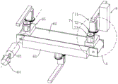
图2是本申请实施例中转角控制组件的结构示意图。Fig. 2 is a schematic structural diagram of the steering angle control assembly in the embodiment of the present application.
图3是本申请实施例中转角控制组件的爆炸图。Fig. 3 is an exploded view of the steering angle control assembly in the embodiment of the present application.
图4是图3中A处的放大图。Fig. 4 is an enlarged view at point A in Fig. 3 .
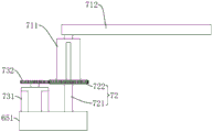
图5是本申请实施例中定位装置的结构示意图。Fig. 5 is a schematic structural diagram of a positioning device in an embodiment of the present application.
图6是本申请实施例中感应件的剖视图。Fig. 6 is a cross-sectional view of the sensing element in the embodiment of the present application.
附图标记说明:Explanation of reference signs:
1、机架;2、放料机构;21、放卷轴;22、导辊;3、牵引机构;31、第一牵引机构;32、压力调节辊;33、第二牵引机构;4、模切机构;41、模切支架;42、上模板;43、下模板;44、冲压头;5、收卷机构;51、安装架;52、废料收卷轴;53、废料收卷电机;54、主料收卷轴;55、主料收卷电机;6、传输件;61、支撑台;62、环形带;63、驱动辊;64、驱转电机;65、连接件;651、连接台;6511、凹槽;652、柔性块;7、定位装置;71、伸缩按压件;711、气缸;712、按压块;72、转台;721、转轴;722、安装台;73、驱转件;731、驱动电机;732、驱动齿轮;8、感应件;81、安装箱;811、杆孔;82、传感器;83、抵杆;84、自回复件;841、回复弹簧;842、固定片。1. Rack; 2. Unwinding mechanism; 21. Unwinding shaft; 22. Guide roller; 3. Traction mechanism; 31. First traction mechanism; 32. Pressure regulating roller; 33. Second traction mechanism; 4. Die-cutting Mechanism; 41, die-cutting support; 42, upper template; 43, lower template; 44, stamping head; 5, winding mechanism; 51, installation frame; 52, waste rewinding shaft; Material winding shaft; 55, main material winding motor; 6, transmission part; 61, supporting platform; 62, endless belt; 63, driving roller; 64, driving motor; 65, connecting piece; Groove; 652, flexible block; 7, positioning device; 71, telescopic pressing piece; 711, cylinder; 712, pressing block; 72, turntable; 721, rotating shaft; Motor; 732, driving gear; 8, induction part; 81, installation box; 811, rod hole; 82, sensor;
具体实施方式Detailed ways
以下结合附图1-6对本申请作进一步详细说明。The present application will be described in further detail below in conjunction with accompanying drawings 1-6.
在本发明的描述中,需要理解的是,术语“中心”、“纵向”、“横向”、“长度”、“宽度”、“厚度”、“上”、“下”、“前”、“后”、“左”、“右”、“竖直”、“水平”、“顶”、“底”、“内”、“外”、“顺时针”、“逆时针”等指示的方位或位置关系为基于附图所示的方位或位置关系,仅是为了便于描述本发明和简化描述,而不是指示或暗示所指的设备或元件必须具有特定的方位、以特定的方位构造和操作,因此不能理解为对本发明的限制。In describing the present invention, it should be understood that the terms "center", "longitudinal", "transverse", "length", "width", "thickness", "upper", "lower", "front", " Orientation indicated by rear, left, right, vertical, horizontal, top, bottom, inside, outside, clockwise, counterclockwise, etc. The positional relationship is based on the orientation or positional relationship shown in the drawings, and is only for the convenience of describing the present invention and simplifying the description, rather than indicating or implying that the referred device or element must have a specific orientation, be constructed and operated in a specific orientation, Therefore, it should not be construed as limiting the invention.
本申请实施例公开一种不干胶商标模切机。The embodiment of the present application discloses a self-adhesive trademark die-cutting machine.
参照图1,不干胶商标模切机包括机架1、放料机构2、牵引机构3、模切机构4、收卷机构5以及转角控制组件。机架1放置在地面上,放料机构2、牵引机构3、模切机构4、收卷机构5和转角控制组件均设置在机架1上,转角控制组件位于模切机构4一侧。Referring to Figure 1, the self-adhesive trademark die-cutting machine includes a frame 1, a feeding mechanism 2, a traction mechanism 3, a die-cutting mechanism 4, a winding mechanism 5 and a corner control assembly. The frame 1 is placed on the ground, and the feeding mechanism 2, the traction mechanism 3, the die-cutting mechanism 4, the winding mechanism 5 and the corner control assembly are all arranged on the frame 1, and the corner control assembly is located at one side of the die-cutting mechanism 4.
商标原料卷放置在放料机构2上,放料机构2将商标输送至模切机构4内,模切机构4对商标进行模切,牵引机构3牵引模切后的商标向收卷机构5移动,同时转角控制机构控制收卷机构5的在转动角度,使得收卷机构5收卷的商标长度与模切机构4完成模切的商标的长度相同。The trademark raw material roll is placed on the unwinding mechanism 2, the unwinding mechanism 2 transports the trademark to the die-cutting mechanism 4, the die-cutting mechanism 4 die-cuts the trademark, and the traction mechanism 3 pulls the die-cut trademark to move to the winding mechanism 5 At the same time, the angle control mechanism controls the rotation angle of the winding mechanism 5, so that the length of the trademark rolled up by the winding mechanism 5 is the same as the length of the trademark that the die-cutting mechanism 4 finishes die-cutting.
放料机构2包括放卷轴21和若干个导辊22,放卷轴21通过放卷盘固定在机架1的左端,本实施例中放卷轴21是气胀轴。若干个导辊22沿机架1的长度方向依次固定在基架上,导辊22的轴向与放卷轴21的轴向相同。The unwinding mechanism 2 includes an unwinding
商标原料卷缠绕在放卷轴21上,商标原料依次绕过若干个导辊22后插入模切机构4内。The trademark raw material roll is wound on the unwinding
模切机构4包括模切支架41、上模板42、下模板43和冲压头44,模切支架41铆接在机架1上,导辊22位于模切支架41和放卷轴21之间,上模板42和下模板43均位于模切支架41内,下模板43与模切支架41固定连接,上模板42位于下模板43正上方,冲压头44安装在模切支架41上,冲压头44位于上模板42上方,冲压头44的底端与上模板42铆接。上模板42的下表面固定连接有刀模板。Die-cutting mechanism 4 comprises die-cutting
商标原料插入上模板42和下模板43之间,商标原料平铺在下模板43上,冲压头44推动上模板42向下移动,当刀模板按压在商标原料上时,刀模板即完成对商标原料的模切。The trademark raw material is inserted between the
参照图1和图2,牵引机构3包括第一牵引机构31、压力调节辊32和第二牵引机构33,第一牵引机构31、压力调节辊32和第二牵引机构33依次安装在机架1上,模切支架41位于第一牵引机构31和导辊22之间。Referring to Fig. 1 and Fig. 2, the traction mechanism 3 comprises a
第一牵引机构31牵引模切后的商标移动至压力调节辊32,压力调节辊32调节模切后商标的张力,第二牵引机构33牵引模切后商标的主料移动,收卷机构5将模切后商标的废料和主料分别进行收卷。The
收卷机构5包括废料收卷机构和主料收卷机构。废料收卷机构包括安装架51、废料收卷轴52和废料收卷电机53,安装架51固定在机架1上,安装架51位于第二牵引机构33右侧,废料收卷轴52和收卷电机均设于安装架51上,收卷电机带动废料收卷轴52转动。主料收卷机构包括主料收卷轴54和主料收卷电机55,主料收卷轴54通过轴承座安装在机架1上,主料收卷电机55带动主料收卷轴54转动,废料收卷轴52位于主料收卷轴54上方。The winding mechanism 5 includes a waste material winding mechanism and a main material winding mechanism. The waste rewinding mechanism comprises a mounting
模切后的商标在经过压力调节辊32后分离成废料和主料,废料缠绕在废料收卷轴52上,主料通过第二牵引机构33的牵引缠绕在主料收卷轴54上,主料收卷电机55驱动主料收卷轴54转动,即可将主料收卷在主料收卷轴54上。同时,废料收卷电机53驱动废料收卷轴52转动,将废料收卷在废料收卷轴52上。The trademark after die cutting is separated into waste material and main material after passing through the pressure regulating roller 32, the waste material is wound on the waste
参照图1和图2,转角控制组件包括传输件6、定位装置7和感应件8。传输件6和感应件8均安装在机架1上,传输件6和感应件8均位于模切支架41的同一侧。定位装置7可以有三个、四个或五个等,本实施例的定位装置7有三个,三个定位装置7均安装在传输件6上,三个定位装置7之间的环形带62的长度相等。Referring to FIG. 1 and FIG. 2 , the steering angle control assembly includes a transmission part 6 , a positioning device 7 and a
先操作一个定位装置7锁定模切机构4中商标原料的某一处,当模切机构4完成模切后,传输件6带动定位装置7与商标同步移动,当感应件8感应到定位装置7移动的距离与密切机构完成模切的长度相等时,感应件8发出信号,收卷机构5和传输件6即停止工作,完成收卷。First operate a positioning device 7 to lock a certain part of the trademark raw material in the die-cutting mechanism 4. After the die-cutting mechanism 4 completes the die-cutting, the transmission part 6 drives the positioning device 7 to move synchronously with the trademark. When the
参照图2和图3,传输件6包括支撑台61、环形带62、驱动辊63、驱转电机64和连接件65,支撑台61焊接在机架1上,环形带62是环形传输带,环形带62套设在支撑台61上,环形带62的内壁与支撑台61的上表面和下表面抵接。驱转电机64铆接在支撑台61上,驱动辊63的一端同轴连接在驱转电机64的电机轴上,驱动辊63的另一端插设于环形带62内并与环形带62的内周壁抵接。With reference to Fig. 2 and Fig. 3, transmission member 6 comprises support table 61,
连接件65安装在环形带62的外周壁上,连接件65的数量与定位装置7的数量相同,相邻的两个连接件65之间的环形带62的长度相等,每个连接件65上安装一个定位装置7。
参照图3和图4,连接件65包括连接台651和柔性块652,连接台651和柔性块652均粘接在环形带62的外周壁上,连接台651朝向环形带62的表面上设有凹槽6511,凹槽6511的长度方向与环形带62的宽度方向相同,凹槽6511长度方向的两端贯穿连接台651的侧壁,柔性块652位于凹槽6511内,且柔性块652与凹槽6511的槽壁粘接。Referring to Fig. 3 and Fig. 4,
参照图4和图5,定位装置7包括伸缩按压件71、转台72和驱转件73,转台72和驱转件73均安装在连接台651上,伸缩按压件71安装在转台72上。转台72包括转轴721和安装台722,转轴721焊接在连接台651上,转轴721沿竖直方向设置。安装台722转动连接在转轴721的顶端。Referring to Fig. 4 and Fig. 5, the positioning device 7 includes a telescopic
驱转件73包括驱动电机731和驱动齿轮732,驱动电机731铆接在连接台651上,驱动电机731的电机轴与转轴721的轴线平行。驱动齿轮732同轴连接在驱动电机731的电机轴上,驱动齿轮732与安装台722的周壁啮合。The driving
伸缩按压件71包括气缸711和按压块712,气缸711沿竖直方向固定连接在安装台722上,按压块712的一端与气缸711的顶端焊接,按压块712沿水平方向设置。The telescopic pressing
启动驱动电机731,驱动齿轮732和安装台722转动,气缸711和按压块712同步转动,当按压块712远离气缸711的一端插入上模板42和下模板43之间时,关闭驱动电机731,然后操作气缸711收缩,按压块712即向下移动并将商标抵紧在下模板43上。Start the driving
参照图4和图6,感应件8包括安装箱81、传感器82、抵杆83和自回复件84。安装箱81铆接在机架1上,安装箱81位于支撑台61的右端。传感器82和自回复件84均位于安装箱81内,传感器82铆接在安装箱81右侧的内箱壁上,安装箱81的左箱壁上设有杆孔811,抵杆83插设于杆孔811内,抵杆83沿水平方向设置。当按压块712将商标抵紧在下模板43上时,抵杆83的左端与按压块712相对,抵杆83的右端与传感器82相对。Referring to FIG. 4 and FIG. 6 , the
自回复件84包括回复弹簧841和固定片842,固定片842焊接在抵杆83上,回复弹簧841可以有一个、两个、三个或四个等,本实施例的回复弹簧841有四个,四个回复弹簧841均与固定片842焊接,回复弹簧841远离固定片842的一端均与安装箱81的右内箱壁焊接,传感器82位于四个回复弹簧841之间。The self-returning
当按压块712与商标同步移动时,按压块712向靠近抵杆83的方向移动,当按压块712与抵杆83接触时,按压块712推动抵杆83向靠近传感器82的方向移动,当抵杆83与传感器82接触时,按压块712移动的距离与模切机构4完成模切的长度相等,此时,传感器82发出信号,传输件6和收卷机构5停止工作,按压块712即停止移动,模切好的商标完成收卷。When the
本申请实施例一种不干胶商标模切机的实施原理为:先将商标原料卷放置在放料轴上,然后将商标插入模切机构4内,然后商标依次穿过第一牵引机构31、压力调节辊32,分离成废料和主料,废料缠绕在废料收卷轴52上,主料穿过第二收卷机构5后缠绕在主料收卷轴54上。The implementation principle of a self-adhesive trademark die-cutting machine in the embodiment of the present application is: first place the trademark raw material roll on the discharge shaft, then insert the trademark into the die-cutting mechanism 4, and then the trademark passes through the
启动驱动电机731,驱动齿轮732驱动安装台722转动,当按压块712插入上模板42和下模板43之间时,关闭驱动电机731。然后启动驱转电机64,驱动辊63驱动环形带62移动,当按压块712移动至支撑台61的左端时,关闭驱转电机64。Start the driving
再操作气缸711收缩,按压块712向下移动并将商标原料按紧在下模板43上。然后操作冲压头44驱动上模板42向下移动,刀模板按压在商标原料上并完成对商标原料的模切。Operate the
然后启动主料收卷电机55、废料收卷电机53和驱转电机64,按压块712与商标同步移动,当按压块712与抵杆83接触后即推动抵杆83移动,同时弹簧发生弹性形变。当抵杆83的右端与传感器82接触时,传感器82发出信号,主料收卷电机55、废料收卷电机53和驱转电机64同时停止转动,模切后的商标即分离成废料和主料分别收卷在废料收卷轴52和主料收卷轴54上。Then start the main
再操作气缸711伸长,按压块712向上移动并与商标脱离接触,启动驱动电机731反向转动,将按压块712转回环形带62的正上方。然后操作左侧相邻的定位装置7按紧商标,重复上述操作,即可完成商标的模切和收卷工作。The
以上均为本申请的较佳实施例,并非依此限制本申请的保护范围,故:凡依本申请的结构、形状、原理所做的等效变化,均应涵盖于本申请的保护范围之内。All of the above are preferred embodiments of the application, and are not intended to limit the protection scope of the application. Therefore, all equivalent changes made according to the structure, shape, and principle of the application should be covered by the protection scope of the application. Inside.
Claims (8)
Priority Applications (1)
| Application Number | Priority Date | Filing Date | Title |
|---|---|---|---|
| CN202310094679.4A CN115991402A (en) | 2023-01-30 | 2023-01-30 | A self-adhesive trademark die-cutting machine |
Applications Claiming Priority (1)
| Application Number | Priority Date | Filing Date | Title |
|---|---|---|---|
| CN202310094679.4A CN115991402A (en) | 2023-01-30 | 2023-01-30 | A self-adhesive trademark die-cutting machine |
Publications (1)
| Publication Number | Publication Date |
|---|---|
| CN115991402A true CN115991402A (en) | 2023-04-21 |
Family
ID=85993375
Family Applications (1)
| Application Number | Title | Priority Date | Filing Date |
|---|---|---|---|
| CN202310094679.4A Withdrawn CN115991402A (en) | 2023-01-30 | 2023-01-30 | A self-adhesive trademark die-cutting machine |
Country Status (1)
| Country | Link |
|---|---|
| CN (1) | CN115991402A (en) |
-
2023
- 2023-01-30 CN CN202310094679.4A patent/CN115991402A/en not_active Withdrawn
Similar Documents
| Publication | Publication Date | Title |
|---|---|---|
| CN201183687Y (en) | Reeled paper non-stop automatic contraposition joint device | |
| US20060185796A1 (en) | Laminating apparatus | |
| JPH0822638B2 (en) | Progressive plotter that moves paper in a fixed direction | |
| CN207243105U (en) | Fully automatic high-speed electronic tag composite mold cutting all-in-one machine | |
| US7533844B2 (en) | Paper splicing apparatus | |
| CN210011333U (en) | Multi-station label laminating device | |
| CN115991402A (en) | A self-adhesive trademark die-cutting machine | |
| CN217102326U (en) | A cutting mechanism for wrapping film production | |
| CN219217123U (en) | A collection reel structure for label production | |
| CN213833883U (en) | Web material adjusting device | |
| CN110884930B (en) | Trademark die-cutting machine | |
| CN113184577A (en) | Children's book production line of visiting | |
| CN103753950A (en) | Digital hot stamping machine | |
| CN116620907B (en) | Adhesive tape laser lithography machine | |
| CN111716405A (en) | Rubberized fabric half-cutting equipment for FFC wire processing | |
| JP2005308225A (en) | Winding foil material support and drive module for a machine for processing the winding foil material | |
| CN213769126U (en) | Die-cutting machine | |
| CN203637329U (en) | Digital hot stamping machine | |
| CN223280342U (en) | Automatic label die-cutting machine | |
| CN115156344A (en) | High-machining-precision numerical control bending machine for metal plates | |
| CN210655466U (en) | Intelligent control printing and die cutting integrated machine | |
| CN215156430U (en) | Automatic labeling device | |
| CN116374359B (en) | Medicine bottle labeling device and labeling method | |
| KR20030008443A (en) | An apparatus for guiding and transforming the top strip of coil | |
| CN222249419U (en) | A tension control device for a rewinding machine |
Legal Events
| Date | Code | Title | Description |
|---|---|---|---|
| PB01 | Publication | ||
| PB01 | Publication | ||
| SE01 | Entry into force of request for substantive examination | ||
| SE01 | Entry into force of request for substantive examination | ||
| WW01 | Invention patent application withdrawn after publication |
Application publication date: 20230421 |
|
| WW01 | Invention patent application withdrawn after publication |