CN116013169A - Curved surface display module and display device - Google Patents
Curved surface display module and display device Download PDFInfo
- Publication number
- CN116013169A CN116013169A CN202310129362.XA CN202310129362A CN116013169A CN 116013169 A CN116013169 A CN 116013169A CN 202310129362 A CN202310129362 A CN 202310129362A CN 116013169 A CN116013169 A CN 116013169A
- Authority
- CN
- China
- Prior art keywords
- support plate
- display panel
- groove
- display module
- grooves
- Prior art date
- Legal status (The legal status is an assumption and is not a legal conclusion. Google has not performed a legal analysis and makes no representation as to the accuracy of the status listed.)
- Pending
Links
Images


Landscapes
- Devices For Indicating Variable Information By Combining Individual Elements (AREA)
Abstract
本申请实施例提供了一种曲面显示模组及显示装置,曲面显示模组包括显示面板和支撑板,显示面板和支撑板之间设有导热胶,显示面板和支撑板的粘接面为弧形,曲面显示模组包括用于加强支撑板与显示面板连接的加强部,加强部为设于支撑板上的凹槽或者加强部为设于支撑板背离显示面板一侧的连接件。显示面板与支撑板之间导热胶粘接,导热胶将显示面板与支撑板相互固定,保持支撑板的弧形状态,凹槽用于降低支撑板的厚度,以降低支撑板的弹性应力,从而降低支撑板与显示面板剥离的风险。或者,加强部为设于支撑板背离显示面板一侧的连接件,连接件用于固定支撑板,连接件用于提供反作用力以抵消支撑板远离显示面板方向的弹性应力。
The embodiment of the present application provides a curved surface display module and a display device. The curved surface display module includes a display panel and a support plate. A heat-conducting adhesive is provided between the display panel and the support plate. The bonding surface of the display panel and the support plate is an arc. The curved surface display module includes a reinforcing part for strengthening the connection between the support plate and the display panel. The reinforcing part is a groove provided on the support plate or a connecting piece provided on the side of the support plate away from the display panel. The display panel and the support plate are bonded with heat-conducting glue, and the heat-conducting glue fixes the display panel and the support plate to each other to maintain the arc-shaped state of the support plate. The groove is used to reduce the thickness of the support plate to reduce the elastic stress of the support plate, thereby Reduces the risk of delamination of the support plate from the display panel. Alternatively, the reinforcing part is a connecting piece provided on the side of the supporting plate away from the display panel, the connecting piece is used to fix the supporting plate, and the connecting piece is used to provide a reaction force to offset the elastic stress of the supporting plate away from the display panel.
Description
技术领域technical field
本申请涉及显示面板技术领域,特别是涉及一种曲面显示模组及显示装置。The present application relates to the technical field of display panels, in particular to a curved display module and a display device.
背景技术Background technique
近年来,由于OLED(Organic Light-Emitting Diode,有机发光二极管)显示器件具有轻薄、柔性可弯曲和对比度较高等优点,其在汽车车载显示领域逐渐开始得到应用,车载显示运行环境较为严苛,信赖性要求更高。OLED显示器件的主要部件为曲面显示模组,曲面显示模组包括显示面板和支撑板,由于曲面显示模组的曲面结构是由支撑板通过弯曲贴合在曲面形的显示面板的背面而形成,弯曲后的支撑板会产生一个与变形方向相反的力,即反弹力,该反弹力的存在容易导致曲面显示模组的显示面板和支撑板产生剥离。In recent years, due to the advantages of OLED (Organic Light-Emitting Diode, organic light-emitting diode) display devices, such as thinness, flexibility and bendability, and high contrast, it has gradually been applied in the field of automotive display, and the operating environment of automotive display is relatively harsh. Sex is more demanding. The main component of the OLED display device is a curved display module. The curved display module includes a display panel and a support plate. Since the curved structure of the curved display module is formed by bending the support plate on the back of the curved display panel, The bent support plate will generate a force opposite to the deformation direction, that is, the rebound force. The existence of the rebound force will easily cause the display panel and the support plate of the curved display module to peel off.
发明内容Contents of the invention
本申请实施例的目的在于提供一种曲面显示模组及显示装置,以减少曲面显示模组的显示面板和支撑板之间容易发生剥离的问题。具体技术方案如下:The purpose of the embodiments of the present application is to provide a curved display module and a display device to reduce the problem of easy peeling between the display panel and the support plate of the curved display module. The specific technical scheme is as follows:
本申请第一方面提出了一种曲面显示模组,包括显示面板和支撑板,所述显示面板和所述支撑板之间设有导热胶,所述显示面板和所述支撑板的粘接面为弧形,所述曲面显示模组包括用于加强所述支撑板与所述显示面板连接的加强部,所述加强部为设于所述支撑板上的凹槽或者所述加强部为设于所述支撑板背离所述显示面板一侧的连接件。The first aspect of the present application proposes a curved display module, including a display panel and a support plate, a thermally conductive adhesive is provided between the display panel and the support plate, and the bonding surface of the display panel and the support plate It is arc-shaped, and the curved surface display module includes a reinforcement part for strengthening the connection between the support plate and the display panel. The reinforcement part is a groove provided on the support plate or the reinforcement part is a A connecting piece on a side of the support plate away from the display panel.
在本申请的一些实施例中,所述凹槽为设于所述支撑板且朝向所述显示面板一侧的第一凹槽,所述第一凹槽的至少部分填充有所述导热胶。In some embodiments of the present application, the groove is a first groove provided on the support plate and facing the side of the display panel, at least a part of the first groove is filled with the thermal conductive glue.
在本申请的一些实施例中,所述第一凹槽中填充有EAA垫块,所述EAA垫块与所述第一凹槽之间填充有所述导热胶。In some embodiments of the present application, the first groove is filled with an EAA pad, and the thermal conductive glue is filled between the EAA pad and the first groove.
在本申请的一些实施例中,所述显示面板的出光面为凸面,所述第一凹槽设于所述支撑板的中部,或者,所述第一凹槽设于所述支撑板的中部及所述支撑板的两侧;所述显示面板的出光面为凹面,所述第一凹槽设于所述支撑板的两侧,或者,所述第一凹槽设于所述支撑板的两侧及中部。In some embodiments of the present application, the light-emitting surface of the display panel is a convex surface, the first groove is set in the middle of the support plate, or the first groove is set in the middle of the support plate and both sides of the support plate; the light-emitting surface of the display panel is a concave surface, the first groove is provided on both sides of the support plate, or the first groove is provided on the support plate sides and middle.
在本申请的一些实施例中,沿所述支撑板的长度方向,位于所述支撑板中部的所述第一凹槽的尺寸为所述支撑板长度的1/3-1/2;沿所述支撑板的宽度方向,所述第一凹槽与所述支撑板的侧边之间的第一间距大于10mm。In some embodiments of the present application, along the length direction of the support plate, the size of the first groove located in the middle of the support plate is 1/3-1/2 of the length of the support plate; In the width direction of the support plate, the first distance between the first groove and the side of the support plate is greater than 10mm.
在本申请的一些实施例中,沿所述支撑板的长度方向,位于所述支撑板两侧的所述第一凹槽的尺寸为所述支撑板的尺寸的1/5-1/4,沿所述支撑板的宽度方向,所述第一凹槽与所述支撑板的侧边之间的第一间距大于10mm。In some embodiments of the present application, along the length direction of the support plate, the size of the first grooves located on both sides of the support plate is 1/5-1/4 of the size of the support plate, Along the width direction of the support plate, a first distance between the first groove and the side of the support plate is greater than 10mm.
在本申请的一些实施例中,所述凹槽为设于所述支撑板且背离所述显示面板一侧的多个阵列排布的第二凹槽。In some embodiments of the present application, the groove is a plurality of second grooves arranged in an array on a side of the support plate and away from the display panel.
在本申请的一些实施例中,所述显示面板的出光面为凸面,阵列排布的所述第二凹槽设于所述支撑板的中部,或者阵列排布所述第二凹槽设于所述支撑板的中部及所述支撑板的两侧;所述显示面板的出光面为凹面,阵列排布的所述第二凹槽设于所述支撑板的两侧,或者,阵列排布的所述第二凹槽设于所述支撑板的两侧及中部。In some embodiments of the present application, the light-emitting surface of the display panel is a convex surface, and the second grooves arranged in an array are arranged in the middle of the support plate, or the second grooves arranged in an array are arranged in a The middle part of the support plate and both sides of the support plate; the light emitting surface of the display panel is a concave surface, and the second grooves arranged in an array are arranged on both sides of the support plate, or arranged in an array The second groove is provided on both sides and the middle of the support plate.
在本申请的一些实施例中,所述第二凹槽具有相互垂直的长轴和短轴,沿所述支撑板的长度方向,所述第二凹槽沿所述短轴排列成列;沿所述支撑板的宽度方向,所述第二凹槽沿所述长轴排列成行,相邻两行所述第二凹槽错位排布。In some embodiments of the present application, the second grooves have a major axis and a minor axis perpendicular to each other, and along the length direction of the support plate, the second grooves are arranged in a row along the minor axis; In the width direction of the support plate, the second grooves are arranged in rows along the long axis, and the second grooves in two adjacent rows are staggered.
在本申请的一些实施例中,所述连接件与所述支撑板具有仿形结构,所述连接件的两侧与所述支撑板可拆卸连接,所述连接件中部设有与所述客户端连接的凸起部。In some embodiments of the present application, the connecting piece and the supporting plate have a profiling structure, both sides of the connecting piece are detachably connected to the supporting plate, and the middle part of the connecting piece is provided with a The raised part of the end connection.
在本申请的一些实施例中,所述显示面板朝向所述支撑板的一侧设有背膜,所述导热胶设于所述背膜和所述支撑板之间。In some embodiments of the present application, a back film is provided on a side of the display panel facing the support plate, and the thermally conductive adhesive is provided between the back film and the support plate.
本申请第二方面提出一种显示装置,所述显示装置包括上述第一方面中任一项所述的曲面显示模组。A second aspect of the present application proposes a display device, the display device comprising the curved display module described in any one of the above first aspects.
本申请实施例提供的曲面显示模组,显示面板与支撑板之间导热胶粘接,导热胶一方面是将显示面板与支撑板相互固定,保持支撑板的弧形状态,另一方面,导热胶起导热作用,将显示面板发出的热量通过导热胶传输至支撑板,通过支撑板将热量散出。曲面显示模组包括加强部,加强部用于加强支撑板与显示面板的连接,也就是说,加强部用于使支撑板的结构与显示面板的弧形结构相适应,降低支撑板由于弯曲存在弹性应力导致其与显示面板剥离的风险。In the curved display module provided by the embodiment of the present application, the thermal conductive adhesive is bonded between the display panel and the support plate. The glue plays a role of heat conduction, and transmits the heat emitted by the display panel to the support plate through the heat conduction glue, and dissipates the heat through the support plate. The curved surface display module includes a reinforcement part, which is used to strengthen the connection between the support plate and the display panel, that is, the reinforcement part is used to adapt the structure of the support plate to the arc structure of the display panel, and reduce the bending of the support plate. Elastic stress leads to the risk of delamination from the display panel.
加强部为设于支撑板上的凹槽,设置凹槽用于降低支撑板的厚度,以降低支撑板的弹性应力,从而降低支撑板与显示面板剥离的风险。凹槽结构不贯穿支撑板,能够保证支撑板的表面积不变,即不损失导热胶的涂布面积,保证导热胶的粘接强度,降低支撑板与显示面板剥离的风险,也不会损失支撑板的散热面积,有助于显示模组的散热。或者,加强部为设于支撑板背离显示面板一侧的连接件,连接件用于固定支撑板,连接件用于提供反作用力以抵消支撑板远离显示面板方向的弹性应力。The reinforcing part is a groove provided on the support plate, and the groove is used to reduce the thickness of the support plate, so as to reduce the elastic stress of the support plate, thereby reducing the risk of peeling off the support plate and the display panel. The groove structure does not penetrate the support plate, which can ensure that the surface area of the support plate remains unchanged, that is, the coating area of the thermally conductive adhesive will not be lost, the bonding strength of the thermally conductive adhesive will be guaranteed, and the risk of peeling off the support plate from the display panel will be reduced, and the support will not be lost. The heat dissipation area of the board is helpful to display the heat dissipation of the module. Alternatively, the reinforcement part is a connecting piece provided on the side of the supporting plate away from the display panel, the connecting piece is used to fix the supporting plate, and the connecting piece is used to provide a reaction force to offset the elastic stress of the supporting plate away from the display panel.
附图说明Description of drawings
为了更清楚地说明本申请实施例或现有技术中的技术方案,下面将对实施例或现有技术描述中所需要使用的附图作简单地介绍,显而易见地,下面描述中的附图仅仅是本申请的一些实施例,对于本领域普通技术人员来讲,还可以根据这些附图获得其他的实施例。In order to more clearly illustrate the technical solutions in the embodiments of the present application or the prior art, the following will briefly introduce the drawings that need to be used in the description of the embodiments or the prior art. Obviously, the accompanying drawings in the following description are only These are some embodiments of the present application, and those skilled in the art can also obtain other embodiments according to these drawings.
图1为一种支撑板弹性应力示意图;Fig. 1 is a schematic diagram of elastic stress of a support plate;
图2为另一种支撑板弹性应力示意图;Fig. 2 is another schematic diagram of supporting plate elastic stress;
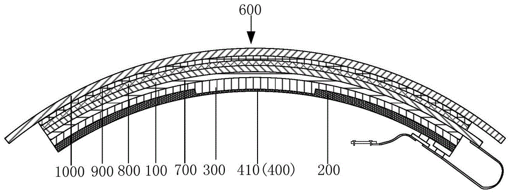
图3为本申请实施例曲面显示模组凸面显示的第一种结构示意图;FIG. 3 is a schematic diagram of the first structure of the convex surface display of the curved surface display module of the embodiment of the present application;
图4为图3中支撑板主视图;Fig. 4 is a front view of the support plate in Fig. 3;
图5为图4中AA’处截面图;Fig. 5 is a sectional view at AA' in Fig. 4;
图6a为支撑板与连接件装配图;Figure 6a is an assembly drawing of the support plate and the connector;
图6b为支撑板上设置第二螺孔的主视图;Fig. 6b is a front view of setting a second screw hole on the support plate;
图7为本申请实施例曲面显示模组凹面显示的第一种结构示意图;Fig. 7 is a schematic diagram of the first structure of the concave surface display of the curved surface display module according to the embodiment of the present application;
图8为图7中支撑板主视图;Figure 8 is a front view of the support plate in Figure 7;
图9为图8中BB’处截面图;Fig. 9 is a sectional view at BB' in Fig. 8;
图10为本申请实施例曲面显示模组凸面显示的第二种结构示意图;FIG. 10 is a schematic diagram of the second structure of the convex display of the curved display module of the embodiment of the present application;
图11为本申请实施例曲面显示模组凹面显示的第二种结构示意图;Fig. 11 is a schematic diagram of the second structure of the concave surface display of the curved surface display module of the embodiment of the present application;
图12为图10和图11中支撑板主视图;Fig. 12 is a front view of the support plate in Fig. 10 and Fig. 11;
图13为本申请实施例曲面显示模组凹面显示的第三种结构示意图;Fig. 13 is a schematic diagram of the third structure of the concave surface display of the curved surface display module according to the embodiment of the present application;
图14为图13中支撑板主视图;Figure 14 is a front view of the support plate in Figure 13;
图15为图14中CC’处截面图;Fig. 15 is a sectional view at CC' in Fig. 14;
图16为第二凹槽结构示意图;Fig. 16 is a schematic diagram of the structure of the second groove;
图17为支撑板设置第二凹槽的另一种主视图;Fig. 17 is another front view in which the support plate is provided with a second groove;
图18为支撑板设置第二凹槽的又一种主视图。Fig. 18 is another front view of the support plate provided with the second groove.
附图标记如下:The reference signs are as follows:
显示面板100,支撑板200,导热胶300,凹槽400,第一凹槽410,EAA垫块420,第二凹槽430,连接件500,凸起部510,螺栓520,第二螺孔530,弧形垫片540,出光面600,背膜700,偏光片800,光学胶层900,玻璃盖板1000,长轴a,短轴b,弹性应力F,长度方向x,宽度方向y,第一间距d1,第二间距d2。
具体实施方式Detailed ways
下面将结合本申请实施例中的附图,对本申请实施例中的技术方案进行清楚、完整地描述,显然,所描述的实施例仅仅是本申请一部分实施例,而不是全部的实施例。基于本申请中的实施例,本领域普通技术人员基于本申请所获得的所有其他实施例,都属于本申请保护的范围。The following will clearly and completely describe the technical solutions in the embodiments of the application with reference to the drawings in the embodiments of the application. Apparently, the described embodiments are only some of the embodiments of the application, not all of them. Based on the embodiments in this application, all other embodiments obtained by persons of ordinary skill in the art based on this application belong to the scope of protection of this application.
相关技术中,如图1和图2所示,由于自身具备可弯折性的支撑板200具有贴合后贴合间隙小,且曲面轮廓度好等优点,一般在曲面显示模组中会使用自带可弯折性的支撑板200。曲面显示模组中的支撑板200具有可弯折特性,可以贴合显示面板100而逐渐弯曲,但是由于其弯曲是由弹性变形引起的,在产生弹性变形后,材料会产生一个与变形方向相反的力,称之为弹性应力F,此弹性应力F的存在可能导致支撑板与显示面板之间发生剥离导致模组无法显示。In the related art, as shown in Fig. 1 and Fig. 2, since the
本申请第一方面提出一种曲面显示模组,如图3至图6a所示,包括显示面板100和支撑板200,显示面板100和支撑板200之间设有导热胶300,显示面板100和支撑板200的粘接面为弧形,曲面显示模组包括用于加强支撑板200与显示面板100连接的加强部,加强部为设于支撑板200上的凹槽400或者加强部为设于支撑板200背离显示面板100一侧的连接件500。The first aspect of the present application proposes a curved display module, as shown in FIG. 3 to FIG. The bonding surface of the
在本实施例中,显示面板100与支撑板200之间导热胶300粘接,导热胶300一方面是将显示面板100与支撑板200相互固定,保持支撑板200的弧形状态,另一方面,导热胶300具有较好的导热、电绝缘性能,显示面板100与支撑板200通过导热胶300粘接,能够加快显示面板100发出的热量向支撑板200的传递,通过支撑板200将热量散出,降低曲面显示模组运行过程中的温度。曲面显示模组包括加强部,加强部用于加强支撑板200与显示面板100的连接,也就是说,加强部用于使支撑板200的结构与显示面板100的弧形结构相适应,降低支撑板200由于弯曲存在弹性应力导致其与显示面板100剥离的风险,进而提升曲面车载显示模组的良率,稳定性等。对于显示模组高温测试,振动测试等信赖性测试方面,较传统技术方案而言,其有利于提高曲面显示模组的结构可靠性,从而促进更高规格信赖性条件的达成。In this embodiment, the thermally
由图3至图6a所示可知,本申请至少有两类具体实施方式:第一类是在支撑板200上设置的凹槽400作为加强部;第二类是在支撑板200背离显示面板100一侧设置连接件500作为加强部。From Figure 3 to Figure 6a, it can be seen that there are at least two types of specific implementations in this application: the first type is the
第一类实施方式:在支撑板200上设置的凹槽400作为加强部。The first type of implementation manner: the
在实际应用中,曲面显示模组至少有两种弯曲方式:一种是出光面600为凸面,另一种是出光面600为凹面。In practical applications, there are at least two ways of bending the curved display module: one is that the light-emitting
如图3、图7、图10、图11所示,不论是出光面600是凸面还是凹面,加强部都可以为设于支撑板200上的凹槽400,设置凹槽400用于降低支撑板200的厚度,以降低支撑板200的弹性应力,从而降低支撑板200与显示面板100剥离的风险。凹槽400结构可降低支撑板200的弹性应力,并且凹槽结构为槽结构,即凹槽400不贯穿支撑板,能够保证支撑板200的支撑强度。As shown in Figure 3, Figure 7, Figure 10, and Figure 11, no matter whether the light-emitting
第二类实施方式:在支撑板200背离显示面板100一侧设置连接件500作为加强部。The second type of implementation manner: on the side of the
如图6a所示,在出光面600为凹面的情况下,加强部为设于支撑板200背离显示面板100一侧的连接件500,连接件500用于固定支撑板200,连接件500用于提供反作用力以抵消支撑板200远离显示面板100方向的弹性应力。另外,在出光面600为为凸面的情况下,与图6a所示方式相似,区别仅在于弯曲的方向。As shown in Figure 6a, when the light-emitting
在上述两类实施方式中,支撑板200的材质都可以优选金属板,具体可以为铝板,金属板具有良好的可弯折特性和韧性,并且金属板散热性能较好,有助于模组散热。In the above two types of implementations, the material of the
在一些实施例中,如图3至图5、图7至图12所示,凹槽400为设于支撑板200且朝向显示面板100一侧的第一凹槽410,第一凹槽410的至少部分填充有导热胶300。In some embodiments, as shown in FIG. 3 to FIG. 5 and FIG. 7 to FIG. 12 , the
在图3至图5、图7至图12所示的实施例中,第一凹槽410设置于支撑板200朝向显示面板100一侧,第一凹槽410的设置减薄了支撑板200部分区域的厚度,也就降低了支撑板200的弹性应力。支撑板200与显示面板100相贴合设置,第一凹槽410的底部与显示面板100之间具有一定的间隔,导热胶300在第一凹槽410处的胶层厚度更大,相对于不设置第一凹槽410的显示模组来说,第一凹槽410处粘接强度更高,有利于降低支撑板200的剥离风险。凹槽结构与通孔相比,能够保证支撑板200的涂胶面积不变,即不损失导热胶300的涂布面积,降低支撑板200与显示面板100剥离的风险。In the embodiment shown in FIG. 3 to FIG. 5 and FIG. 7 to FIG. 12 , the
在一些实施例中,如图10和图11所示,第一凹槽410中填充有EAA(EthyleneAcrylic Acid,乙烯丙烯酸共聚物)垫块420,EAA垫块420与第一凹槽410之间填充有导热胶300。In some embodiments, as shown in FIG. 10 and FIG. 11 , the
在本实施例中,EAA材料具有粘结特性好,韧性高的特点。支撑板200上包括弹性应力的方向朝向远离显示面板100的第一区域,还包括弹性应力的方向朝向显示面板100的第二区域。第一凹槽410可以开设在第一区域,由于EAA垫块420粘接特性好,将EAA垫块420设置在第一凹槽410中,相对于显示面板100和支撑板200直接粘接的方式来说,EAA垫块420与显示面板100之间的粘接强度以及EAA垫块420与第一凹槽410之间的粘接强度均大于显示面板100与支撑板200直接粘接的粘接强度,降低支撑板200与显示面板100的剥离风险;第一凹槽410可以开设在第二区域,由于第二区域处支撑板200的弹性应力朝向显示面板100,由于EAA垫块420韧性较高,EAA垫块420受到第一凹槽410和显示面板100的挤压时可以起到缓冲减震作用,防止朝向显示面板方向的弹性应力对显示面板100挤压导致封装层破裂进而引起异常显示等不良。In this embodiment, the EAA material has the characteristics of good bonding properties and high toughness. The
具体的,位于第一区域的EAA垫块厚度优选0.2-0.5mm,位于第二区域的EAA垫块厚度优选0.3-0.6mm。EAA垫块与支撑板200之间的导热胶300的厚度大于50微米。Specifically, the thickness of the EAA pad located in the first area is preferably 0.2-0.5 mm, and the thickness of the EAA pad located in the second area is preferably 0.3-0.6 mm. The thickness of the thermally conductive adhesive 300 between the EAA block and the
在一些实施例中,如图3所示,显示面板100的出光面600为凸面,第一凹槽410设于支撑板200的中部,或者,如图10和图12所示,第一凹槽410设于支撑板200的中部及支撑板200的两侧。如图7所示,显示面板100的出光面600为凹面,第一凹槽410设于支撑板200的两侧,或者,如图11至图12所示,第一凹槽410设于支撑板200的两侧及中部。In some embodiments, as shown in FIG. 3 , the light-emitting
在本实施例中,显示面板100的出光面600位于显示面板100背离支撑板200一侧。出光面600为凸面时,支撑板200与显示面板100粘合后,支撑板200中部产生远离显示面板100表面方向的弹性应力,在支撑板200中部设置第一凹槽410,减薄支撑板200中间位置的厚度,减小支撑板200中部远离显示面板100表面方向的弹性应力,避免产生支撑板200中部与显示面板100相互剥离的现象。当显示模组的出光面600为凹面时,支撑板200与显示面板100粘合后,支撑板200两侧产生远离显示面板100表面方向的弹性应力,在支撑板200两侧分别设置第一凹槽410,减薄支撑板200两侧位置的厚度,减小支撑板200两侧远离显示面板100表面方向的弹性应力,避免产生支撑板200两侧与显示面板100相互剥离的现象。In this embodiment, the
进一步的,当显示模组的出光面600为凸面时,支撑板200与显示面板100粘合后,支撑板200中部产生远离显示面板100表面方向的弹性应力,支撑板200两侧产生压向显示面板100方向的弹性应力,或者当显示模组的出光面600为凹面时,支撑板200与显示面板100粘合后,支撑板200两侧产生远离显示面板100表面方向的弹性应力,支撑板200中部产生压向显示面板100方向的弹性应力。在出光面600为凸面时,通过在支撑板200两侧也设置第一凹槽410,减小支撑板200两侧压向显示面板100方向的弹性应力,防止支撑板200对显示面板100产生挤压导致封装层破裂进而引起异常显示等不良,能够减小支撑板200两侧的朝向显示面板方向的弹性应力对支撑板200中部产生的反作用力,从而可以减小支撑板200中部远离显示面板100的反弹力的大小,降低支撑板200中部与显示面板发生剥离的风险。在出光面600为凹面时,通过在支撑板200中部设置第一凹槽410,减薄支撑板200中间位置的厚度,减小支撑板200中部压向显示面板100方向的弹性应力,并且能够减小支撑板200中部的朝向显示面板100方向的弹性应力对支撑板200两侧产生的反作用力,从而可以减小支撑板200两侧远离显示面板100的反弹力的大小,降低支撑板200两侧与显示面板发生剥离的风险。Furthermore, when the light-emitting
并且,无论显示面板100的出光面600是凸面还是凹面,第一凹槽410设于支撑板200的中部及支撑板200的两侧,均有利于增强显示面板100和支撑板200之间的涂胶厚度,增强粘接强度,有利于防止剥离。Moreover, regardless of whether the light-emitting
在一些实施例中,如图4所示,沿支撑板200的长度方向,位于支撑板200中部的第一凹槽410的尺寸为支撑板200长度的1/3-1/2;沿支撑板200的宽度方向,第一凹槽410与支撑板200的侧边之间的第一间距d1大于10mm。In some embodiments, as shown in FIG. 4, along the length direction of the
在本实施例中,如图4所示,x为支撑板200的长度方向,位于支撑板200中部的第一凹槽410的尺寸为支撑板200长度的1/3-1/2。图中y为支撑板200的宽度方向,沿支撑板200的宽度方向y,第一凹槽410与支撑板200的侧边之间的第一间距d1大于10mm,目的在于为支撑板200边缘留有一定的厚度,第一凹槽410沿宽度方向y不贯穿支撑板200,能够提高支撑板200的整体强度。具体地,第一凹槽410与侧边之间的第一间距d1可以为10mm、15mm、20mm、25mm、30mm等,第一凹槽410与侧边之间的第一间距d1具体可以根据支撑板200的弹性应力大小来确定,当支撑板200存在的弹性应力越大,则将第一凹槽410与侧边之间的第一间距d1设置的越小;当支撑板200存在的弹性应力越小,则将第一凹槽410与侧边之间的第一间距d1设置的越大。In this embodiment, as shown in FIG. 4 , x is the length direction of the
在一些实施例中,如图8所示,沿支撑板200的长度方向,位于支撑板200两侧的第一凹槽410的尺寸为支撑板200的尺寸的1/5-1/4,沿支撑板200的宽度方向y,第一凹槽410与支撑板200的侧边之间的第一间距d1大于10mm。In some embodiments, as shown in FIG. 8 , along the length direction of the
在本实施例中,沿支撑板200的长度方向x,位于支撑板200两侧的第一凹槽410的尺寸为支撑板200的尺寸的1/5-1/4。沿支撑板200的宽度方向y,第一凹槽410与支撑板200的侧边之间的第一间距d1大于10mm,目的在于为支撑板200边缘留有一定的厚度,第一凹槽410与侧边之间的第一间距d1可以为10mm、15mm、20mm、25mm、30mm等,第一凹槽410与侧边之间的第一间距d1具体可以根据支撑板200的弹性应力大小来确定,当支撑板200存在的弹性应力越大,则将第一凹槽410与侧边之间的第一间距d1设置的越小;当支撑板200存在的弹性应力越小,则将第一凹槽410与侧边之间的第一间距d1设置的越大。In this embodiment, along the length direction x of the
在一些实施例中,如图8所示,沿支撑板200的长度方向,第一凹槽410位于支撑板200两侧,第一凹槽410与支撑板200的侧边之间的第二间距d2大于10mm。In some embodiments, as shown in FIG. 8 , along the length direction of the
在本实施例中,第一凹槽410与支撑板200的侧边之间的间距包括第一凹槽410沿支撑板200长度方向与支撑板200侧边之间的第二间距d2,第一凹槽410与支撑板200的侧边之间的间距还包括第一凹槽410沿支撑板200宽度方向与支撑板200侧边之间的第一间距d1。第一凹槽410与支撑板200的侧边之间的第二间距d2大于10mm,目的在于为支撑板200边缘留有一定的厚度,第一凹槽410与侧边之间的第二间距d2可以为10mm、15mm、20mm、25mm、30mm等,第一凹槽410与侧边之间的第二间距d2具体可以根据支撑板200的弹性应力大小来确定,当支撑板200存在的弹性应力越大,则将第一凹槽410与侧边之间的第二间距d2设置的越小;当支撑板200存在的弹性应力越小,则将第一凹槽410与侧边之间的第二间距d2设置的越大。In this embodiment, the distance between the
在一些实施例中,如图13至图15所示,凹槽400为设于支撑板200且背离显示面板100一侧的多个阵列排布的第二凹槽430。In some embodiments, as shown in FIGS. 13 to 15 , the
在本实施例中,第二凹槽430位于支撑板200背离显示面板100一侧,第二凹槽430为槽结构,也就是第二凹槽430不贯穿支撑板200,保证支撑板200靠近显示面板100一侧为平面,不损失支撑板200与显示面板100的接触面积,也就不损失导热胶300的涂布面积,保证支撑板200与显示面板100之间的粘接强度,降低支撑板200与显示面板100的剥离风险。并且,还能保证支撑板200较大的散热面积,有助于曲面显示模组散热。In this embodiment, the
多个第二凹槽430位于支撑板200背离显示面板100一侧,并且,第二凹槽430为阵列排布,有利于支撑板200在弯曲成型过程中弹性应力的释放,第二凹槽430在一定范围内产生形变。在显示面板100和支撑板200进行成型工艺时,第二凹槽430可随着支撑板200弯曲过程产生形变,使得支撑板200的形状随着显示面板100的形状而改变,避免支撑板200与显示面板100出现剥离现象。A plurality of
在一些实施例中,如图13至图18,显示面板100的出光面600为凸面,阵列排布的第二凹槽430设于支撑板200的中部,或者阵列排布第二凹槽430设于支撑板200的中部及支撑板200的两侧;显示面板100的出光面600为凹面,阵列排布的第二凹槽430设于支撑板200的两侧,或者,阵列排布的第二凹槽430设于支撑板200的两侧及中部。In some embodiments, as shown in FIG. 13 to FIG. 18 , the light-emitting
在本实施例中,显示面板100的出光面600位于显示面板100背离支撑板200一侧。出光面600为凸面时,支撑板200中部产生远离显示面板100表面方向的弹性应力,在支撑板200中部设置第二凹槽430,减薄支撑板200中间位置的厚度,减小支撑板200中部远离显示面板100的弹性应力,避免产生支撑板200中部与显示面板100相互剥离的现象。当显示模组的出光面600为凹面时,支撑板200两侧产生远离显示面板100表面方向的弹性应力,在支撑板200两侧分别设置第二凹槽430,减薄支撑板200两侧位置的厚度,减小支撑板200两侧远离显示面板100表面方向的弹性应力,避免产生支撑板200两侧与显示面板100相互剥离的现象。In this embodiment, the
进一步的,当显示模组的出光面600为凸面时,支撑板200两侧由于弯曲而产生压向显示面板100方向的弹性应力,或者当显示模组的出光面600为凹面时,支撑板200中部由于弯曲而产生压向显示面板100方向的弹性应力,并且能够减小支撑板200中部的朝向显示面板100方向的弹性应力对支撑板200两侧产生的反作用力。在出光面600为凹面时,通过在支撑板200中部设置第二凹槽430,减薄支撑板200中间位置的厚度,减小支撑板200中部压向显示面板100方向的弹性应力;在出光面600为凸面时,通过在支撑板200两侧设置第二凹槽430,减小支撑板200两侧压向显示面板100方向的弹性应力,并且能够减小支撑板200两侧的朝向显示面板100方向的弹性应力对支撑板200中部产生的反作用力。防止支撑板200对显示面板100产生挤压导致封装层破裂进而引起异常显示等不良。且阵列排布的第二凹槽430,相比于阵列排布的通孔,对于支撑板200的自身强度的削弱更小,在弯曲后减小反弹力的同时,有助于提高支撑板200的强度。Further, when the light-emitting
在一些实施例中,如图16至图17所示,第二凹槽430具有相互垂直的长轴a和短轴b,沿支撑板200的长度方向,第二凹槽430沿短轴b排列成列;沿支撑板200的宽度方向,第二凹槽430沿长轴a排列成行,相邻两行第二凹槽430错位排布。In some embodiments, as shown in FIGS. 16 to 17 , the
在本实施例中,相邻两列第二凹槽430错位分布,错位分布的第二凹槽430可使形成的凹槽400结构力学特性更加均匀,从而更有利于弹性应力的释放。在此需说明的是,相邻两行的第二凹槽430在进行错位排布时,错位排布具体方式不受限制,只要相邻两行第二凹槽430在排布时不完全正对即可。优选地,其中一行的第二凹槽430的短轴b位于相邻一行的两个第二凹槽430之间。In this embodiment, two adjacent rows of
在一些实施例中,如图6a所示,连接件500与支撑板200具有仿形结构,连接件500的两侧与支撑板200可拆卸连接,连接件500中部设有与客户端连接的凸起部510。In some embodiments, as shown in Figure 6a, the
在本实施例中,连接件500与支撑板200具有仿形结构,也就是连接件500与支撑板200相贴合的一面形状相同,具体的,连接件500与支撑板200相贴合的一面均为弧形,且弧度相同。连接件500的两侧与支撑板200可拆卸连接,也就是连接件500与支撑板200相互固定,防止连接件500与固定板相互剥离。In this embodiment, the connecting
具体的,当出光面600为凸面时,支撑板200中部向显示面板100方向弯曲,支撑板200中部产生远离显示面板100表面方向的弹性应力,也就是支撑板200中部产生朝向连接件500方向的压力,连接件500则与此压力相抵,防止支撑板200中部向远离显示面板100的方向运动,避免产生支撑板200中部与显示面板100相互剥离的现象。当出光面600为凹面时,支撑板200两侧向显示面板100方向弯曲,支撑板200两侧产生远离显示面板100表面方向的弹性应力,也就是支撑板200两侧产生朝向连接件500方向的压力,连接件500则与此压力相抵,防止支撑板200两侧向远离显示面板100的方向运动,避免产生支撑板200两侧与显示面板100相互剥离的现象。Specifically, when the light-emitting
连接件500中部设有与客户端连接的凸起部510,凸起部510与连接件500在客户端的安装位置相适配,也就是连接件500通过凸起部510安装于客户端,进一步的,在凸起部510可以设置有控制器、电路板以及数据接口等部件用于与客户端进行交互。The middle part of the connecting
在一些实施例中,如图6a和图6b所示,连接件500两侧设置有第一螺孔以及在第一螺孔中的螺栓520,支撑板200靠近连接件500一侧与第一螺孔对应位置设置有第二螺孔530,螺栓520端部位于第二螺孔530用于将支撑板200与连接件500固定。In some embodiments, as shown in Figure 6a and Figure 6b, first screw holes and
在本实施例中,螺栓520包括头部和螺杆,螺杆一部分位于第一螺孔,螺杆另一部分位于第二螺孔530,头部位于连接件500远离支撑板200一侧,头部与支撑板200之间设置有弧形垫片540。In this embodiment, the
在一些实施例中,如图3所示,显示面板100朝向支撑板200的一侧设有背膜700,导热胶300设于背膜700和支撑板200之间。In some embodiments, as shown in FIG. 3 , a
在本实施例中,背膜700可以为透明的绝缘材质,例如涤纶树脂,用于起到保护和支撑显示面板100的作用。In this embodiment, the
在一些实施例中,如图3所示,显示面板的出光面600一侧沿远离100方向依次设置有偏光片800、光学胶层900以及玻璃盖板1000。In some embodiments, as shown in FIG. 3 , a
本申请第二方面提出一种显示装置,显示装置包括上述第一方面中任一实施例中的曲面显示模组。The second aspect of the present application provides a display device, which includes the curved display module in any one of the embodiments of the first aspect above.
在本实施例中,显示装置采用的曲面显示模组中,显示面板100与支撑板200之间导热胶300粘接,导热胶300一方面是将显示面板100与支撑板200相互固定,保持支撑板200的弧形状态,另一方面,导热胶300起导热作用,将显示面板100发出的热量通过导热胶300传输至支撑板200,通过支撑板200将热量散出。曲面显示模组包括加强部,加强部用于加强支撑板200与显示面板100的连接,也就是说,加强部用于使支撑板200的结构与显示面板100的弧形结构相适应,降低支撑板200由于弯曲存在弹性应力导致其与显示面板100剥离的风险。In this embodiment, in the curved display module used in the display device, the thermally
加强部为设于支撑板200上的凹槽400,设置凹槽400用于降低支撑板200的厚度,以降低支撑板200的弹性应力,从而降低支撑板200与显示面板100剥离的风险。凹槽400结构在降低弹性应力的同时,又能够保证支撑板200的支撑强度。The reinforcing part is a
或者,加强部为设于支撑板200背离显示面板100一侧的连接件500,连接件500用于固定支撑板200,连接件500用于提供反作用力以抵消支撑板200远离显示面板100方向的弹性应力。Alternatively, the reinforcing part is a connecting
需要说明的是,在本文中,诸如第一和第二等之类的关系术语仅仅用来将一个实体或者操作与另一个实体或操作区分开来,而不一定要求或者暗示这些实体或操作之间存在任何这种实际的关系或者顺序。而且,术语“包括”、“包含”或者其任何其他变体意在涵盖非排他性的包含,从而使得包括一系列要素的过程、方法、物品或者设备不仅包括那些要素,而且还包括没有明确列出的其他要素,或者是还包括为这种过程、方法、物品或者设备所固有的要素。在没有更多限制的情况下,由语句“包括一个……”限定的要素,并不排除在包括要素的过程、方法、物品或者设备中还存在另外的相同要素。It should be noted that in this article, relational terms such as first and second are only used to distinguish one entity or operation from another entity or operation, and do not necessarily require or imply that there is a relationship between these entities or operations. There is no such actual relationship or order between them. Furthermore, the term "comprises", "comprises" or any other variation thereof is intended to cover a non-exclusive inclusion such that a process, method, article, or apparatus comprising a set of elements includes not only those elements, but also includes elements not expressly listed. other elements of or also include elements inherent in such a process, method, article, or device. Without further limitations, an element defined by the phrase "comprising a ..." does not preclude the presence of additional identical elements in the process, method, article, or apparatus that includes the element.
本说明书中的各个实施例均采用相关的方式描述,各个实施例之间相同相似的部分互相参见即可,每个实施例重点说明的都是与其他实施例的不同之处。Each embodiment in this specification is described in a related manner, the same and similar parts of each embodiment can be referred to each other, and each embodiment focuses on the differences from other embodiments.
以上仅为本申请的较佳实施例,并非用于限定本申请的保护范围。凡在本申请的精神和原则之内所作的任何修改、等同替换、改进等,均包含在本申请的保护范围内。The above are only preferred embodiments of the present application, and are not intended to limit the protection scope of the present application. Any modifications, equivalent replacements, improvements, etc. made within the spirit and principles of this application are included within the protection scope of this application.
Claims (12)
Priority Applications (1)
| Application Number | Priority Date | Filing Date | Title |
|---|---|---|---|
| CN202310129362.XA CN116013169A (en) | 2023-02-16 | 2023-02-16 | Curved surface display module and display device |
Applications Claiming Priority (1)
| Application Number | Priority Date | Filing Date | Title |
|---|---|---|---|
| CN202310129362.XA CN116013169A (en) | 2023-02-16 | 2023-02-16 | Curved surface display module and display device |
Publications (1)
| Publication Number | Publication Date |
|---|---|
| CN116013169A true CN116013169A (en) | 2023-04-25 |
Family
ID=86023229
Family Applications (1)
| Application Number | Title | Priority Date | Filing Date |
|---|---|---|---|
| CN202310129362.XA Pending CN116013169A (en) | 2023-02-16 | 2023-02-16 | Curved surface display module and display device |
Country Status (1)
| Country | Link |
|---|---|
| CN (1) | CN116013169A (en) |
Citations (8)
| Publication number | Priority date | Publication date | Assignee | Title |
|---|---|---|---|---|
| US6927344B1 (en) * | 2004-02-27 | 2005-08-09 | Motorola, Inc. | Flexible circuit board assembly |
| US20070117418A1 (en) * | 2005-11-21 | 2007-05-24 | Yuji Azuma | Display apparatus |
| CN104464520A (en) * | 2014-12-02 | 2015-03-25 | 青岛海信电器股份有限公司 | Curved-surface display equipment |
| CN204516279U (en) * | 2014-11-10 | 2015-07-29 | 友达光电股份有限公司 | Curved surface display |
| CN104916227A (en) * | 2015-06-18 | 2015-09-16 | 奥英光电(苏州)有限公司 | Back plate assembly of curved surface displayer |
| CN113287159A (en) * | 2019-12-20 | 2021-08-20 | 京东方科技集团股份有限公司 | Curved surface display device and vehicle |
| CN113744630A (en) * | 2020-05-28 | 2021-12-03 | 云谷(固安)科技有限公司 | Display module, manufacturing method of display module and display device |
| CN216450311U (en) * | 2021-06-29 | 2022-05-06 | 惠科股份有限公司 | Curved surface display module |
-
2023
- 2023-02-16 CN CN202310129362.XA patent/CN116013169A/en active Pending
Patent Citations (8)
| Publication number | Priority date | Publication date | Assignee | Title |
|---|---|---|---|---|
| US6927344B1 (en) * | 2004-02-27 | 2005-08-09 | Motorola, Inc. | Flexible circuit board assembly |
| US20070117418A1 (en) * | 2005-11-21 | 2007-05-24 | Yuji Azuma | Display apparatus |
| CN204516279U (en) * | 2014-11-10 | 2015-07-29 | 友达光电股份有限公司 | Curved surface display |
| CN104464520A (en) * | 2014-12-02 | 2015-03-25 | 青岛海信电器股份有限公司 | Curved-surface display equipment |
| CN104916227A (en) * | 2015-06-18 | 2015-09-16 | 奥英光电(苏州)有限公司 | Back plate assembly of curved surface displayer |
| CN113287159A (en) * | 2019-12-20 | 2021-08-20 | 京东方科技集团股份有限公司 | Curved surface display device and vehicle |
| CN113744630A (en) * | 2020-05-28 | 2021-12-03 | 云谷(固安)科技有限公司 | Display module, manufacturing method of display module and display device |
| CN216450311U (en) * | 2021-06-29 | 2022-05-06 | 惠科股份有限公司 | Curved surface display module |
Similar Documents
| Publication | Publication Date | Title |
|---|---|---|
| US7443678B2 (en) | Flexible circuit board with heat sink | |
| JP5881860B2 (en) | Power module | |
| US7462880B2 (en) | Semiconductor light-emitting element assembly | |
| KR20200104770A (en) | Circuit board module and heat-dissipating board structure thereof | |
| CN102230588B (en) | Backlight module and liquid crystal display | |
| CN112908180B (en) | Flexible Display Module | |
| CN114420865B (en) | OLED display module and OLED display device | |
| CN112802807A (en) | Chip heat dissipation device and manufacturing method | |
| JP2010238540A (en) | Light emitting module and manufacturing method thereof | |
| CN116013169A (en) | Curved surface display module and display device | |
| CN113795079A (en) | Power semiconductor device mounting structure and modular manufacturing method | |
| CN101441357A (en) | Light-emitting module, forming method of light-emitting module and application of light-emitting module | |
| JP2022125612A (en) | power module | |
| CN114630571B (en) | Side heat radiation structure of optical module | |
| CN217445695U (en) | Optical module side heat radiation structure | |
| JP2014135374A (en) | Heat transfer substrate | |
| JP3680349B2 (en) | Heat dissipation structure | |
| JP4466692B2 (en) | Semiconductor device | |
| CN102606903A (en) | Light source module | |
| CN223488603U (en) | Heat dissipating device and display module | |
| WO2009012726A1 (en) | A non-insulating led | |
| CN223829820U (en) | Heat dissipation structure and chip components | |
| JP2016178237A (en) | Cooling device | |
| CN116679483B (en) | Backlight module and display device | |
| KR101294505B1 (en) | The radiant heat circuit board and the chassis structure having the same |
Legal Events
| Date | Code | Title | Description |
|---|---|---|---|
| PB01 | Publication | ||
| PB01 | Publication | ||
| SE01 | Entry into force of request for substantive examination | ||
| SE01 | Entry into force of request for substantive examination |