CN116018174A - Flexible Shafts for Medical Device Delivery Systems - Google Patents
Flexible Shafts for Medical Device Delivery Systems Download PDFInfo
- Publication number
- CN116018174A CN116018174A CN202180054343.4A CN202180054343A CN116018174A CN 116018174 A CN116018174 A CN 116018174A CN 202180054343 A CN202180054343 A CN 202180054343A CN 116018174 A CN116018174 A CN 116018174A
- Authority
- CN
- China
- Prior art keywords
- segments
- catheter
- leg
- ball
- socket
- Prior art date
- Legal status (The legal status is an assumption and is not a legal conclusion. Google has not performed a legal analysis and makes no representation as to the accuracy of the status listed.)
- Pending
Links
Images



Classifications
-
- A—HUMAN NECESSITIES
- A61—MEDICAL OR VETERINARY SCIENCE; HYGIENE
- A61F—FILTERS IMPLANTABLE INTO BLOOD VESSELS; PROSTHESES; DEVICES PROVIDING PATENCY TO, OR PREVENTING COLLAPSING OF, TUBULAR STRUCTURES OF THE BODY, e.g. STENTS; ORTHOPAEDIC, NURSING OR CONTRACEPTIVE DEVICES; FOMENTATION; TREATMENT OR PROTECTION OF EYES OR EARS; BANDAGES, DRESSINGS OR ABSORBENT PADS; FIRST-AID KITS
- A61F2/00—Filters implantable into blood vessels; Prostheses, i.e. artificial substitutes or replacements for parts of the body; Appliances for connecting them with the body; Devices providing patency to, or preventing collapsing of, tubular structures of the body, e.g. stents
- A61F2/02—Prostheses implantable into the body
- A61F2/24—Heart valves ; Vascular valves, e.g. venous valves; Heart implants, e.g. passive devices for improving the function of the native valve or the heart muscle; Transmyocardial revascularisation [TMR] devices; Valves implantable in the body
- A61F2/2427—Devices for manipulating or deploying heart valves during implantation
-
- A—HUMAN NECESSITIES
- A61—MEDICAL OR VETERINARY SCIENCE; HYGIENE
- A61F—FILTERS IMPLANTABLE INTO BLOOD VESSELS; PROSTHESES; DEVICES PROVIDING PATENCY TO, OR PREVENTING COLLAPSING OF, TUBULAR STRUCTURES OF THE BODY, e.g. STENTS; ORTHOPAEDIC, NURSING OR CONTRACEPTIVE DEVICES; FOMENTATION; TREATMENT OR PROTECTION OF EYES OR EARS; BANDAGES, DRESSINGS OR ABSORBENT PADS; FIRST-AID KITS
- A61F2/00—Filters implantable into blood vessels; Prostheses, i.e. artificial substitutes or replacements for parts of the body; Appliances for connecting them with the body; Devices providing patency to, or preventing collapsing of, tubular structures of the body, e.g. stents
- A61F2/95—Instruments specially adapted for placement or removal of stents or stent-grafts
- A61F2/9517—Instruments specially adapted for placement or removal of stents or stent-grafts handle assemblies therefor
-
- A—HUMAN NECESSITIES
- A61—MEDICAL OR VETERINARY SCIENCE; HYGIENE
- A61M—DEVICES FOR INTRODUCING MEDIA INTO, OR ONTO, THE BODY; DEVICES FOR TRANSDUCING BODY MEDIA OR FOR TAKING MEDIA FROM THE BODY; DEVICES FOR PRODUCING OR ENDING SLEEP OR STUPOR
- A61M25/00—Catheters; Hollow probes
- A61M25/01—Introducing, guiding, advancing, emplacing or holding catheters
- A61M25/0105—Steering means as part of the catheter or advancing means; Markers for positioning
- A61M25/0133—Tip steering devices
- A61M25/0138—Tip steering devices having flexible regions as a result of weakened outer material, e.g. slots, slits, cuts, joints or coils
-
- A—HUMAN NECESSITIES
- A61—MEDICAL OR VETERINARY SCIENCE; HYGIENE
- A61F—FILTERS IMPLANTABLE INTO BLOOD VESSELS; PROSTHESES; DEVICES PROVIDING PATENCY TO, OR PREVENTING COLLAPSING OF, TUBULAR STRUCTURES OF THE BODY, e.g. STENTS; ORTHOPAEDIC, NURSING OR CONTRACEPTIVE DEVICES; FOMENTATION; TREATMENT OR PROTECTION OF EYES OR EARS; BANDAGES, DRESSINGS OR ABSORBENT PADS; FIRST-AID KITS
- A61F2/00—Filters implantable into blood vessels; Prostheses, i.e. artificial substitutes or replacements for parts of the body; Appliances for connecting them with the body; Devices providing patency to, or preventing collapsing of, tubular structures of the body, e.g. stents
- A61F2/02—Prostheses implantable into the body
- A61F2/24—Heart valves ; Vascular valves, e.g. venous valves; Heart implants, e.g. passive devices for improving the function of the native valve or the heart muscle; Transmyocardial revascularisation [TMR] devices; Valves implantable in the body
- A61F2/2427—Devices for manipulating or deploying heart valves during implantation
- A61F2/2436—Deployment by retracting a sheath
-
- A—HUMAN NECESSITIES
- A61—MEDICAL OR VETERINARY SCIENCE; HYGIENE
- A61F—FILTERS IMPLANTABLE INTO BLOOD VESSELS; PROSTHESES; DEVICES PROVIDING PATENCY TO, OR PREVENTING COLLAPSING OF, TUBULAR STRUCTURES OF THE BODY, e.g. STENTS; ORTHOPAEDIC, NURSING OR CONTRACEPTIVE DEVICES; FOMENTATION; TREATMENT OR PROTECTION OF EYES OR EARS; BANDAGES, DRESSINGS OR ABSORBENT PADS; FIRST-AID KITS
- A61F2/00—Filters implantable into blood vessels; Prostheses, i.e. artificial substitutes or replacements for parts of the body; Appliances for connecting them with the body; Devices providing patency to, or preventing collapsing of, tubular structures of the body, e.g. stents
- A61F2/95—Instruments specially adapted for placement or removal of stents or stent-grafts
- A61F2/962—Instruments specially adapted for placement or removal of stents or stent-grafts having an outer sleeve
- A61F2/966—Instruments specially adapted for placement or removal of stents or stent-grafts having an outer sleeve with relative longitudinal movement between outer sleeve and prosthesis, e.g. using a push rod
Landscapes
- Health & Medical Sciences (AREA)
- Biomedical Technology (AREA)
- Engineering & Computer Science (AREA)
- Cardiology (AREA)
- Life Sciences & Earth Sciences (AREA)
- Veterinary Medicine (AREA)
- Heart & Thoracic Surgery (AREA)
- Animal Behavior & Ethology (AREA)
- General Health & Medical Sciences (AREA)
- Public Health (AREA)
- Oral & Maxillofacial Surgery (AREA)
- Transplantation (AREA)
- Vascular Medicine (AREA)
- Anesthesiology (AREA)
- Hematology (AREA)
- Pulmonology (AREA)
- Biophysics (AREA)
- Prostheses (AREA)
Abstract
The system includes a control handle portion and a catheter portion coupled to the control handle portion at a proximal end of the catheter portion. The catheter section includes an outer shaft. The outer shaft includes a plurality of segments arranged in an axial direction to form the outer shaft of the catheter portion, each of the plurality of segments configured to move relative to one another. The system also includes a distal portion coupled to a distal end of the outer shaft, the distal portion configured to receive the implantable medical device.
Description
Technical Field
The present technology relates generally to medical devices. And more particularly to delivery systems for stents, prosthetic heart valves, and other implantable medical devices.
Background
Patients suffering from various medical conditions or diseases may require surgery to install an implantable medical device. For example, prosthetic heart valves may be used to treat regurgitation of valves or stenotic calcification of heart valve leaflets. Traditional surgical procedures for implanting prosthetic heart valves require sternotomy and cardiopulmonary bypass procedures, which can cause serious trauma and discomfort to the patient. Traditional surgery may also require long recovery and may lead to life threatening complications.
An alternative to traditional surgical procedures is the use of minimally invasive techniques to deliver implantable medical devices. For example, prosthetic heart valves can be delivered percutaneously and transluminally to the implantation site. In such methods, the prosthetic heart valve may be compressed or crimped onto or into a delivery catheter of a delivery system for insertion into the vasculature of a patient; advancing to an implantation site; and re-expanding for deployment at the implantation site.
The delivery catheter of the delivery system typically includes a shaft that provides structural support for the delivery catheter. In some current devices, the shaft of the delivery system contains two spinal wires that run along the length of both the intima and media that provide structural support. Due to the stiffness and arrangement of the spinal cord, the shaft can only bend or flex in one plane. This limited range of motion can cause problems when tracking an implantable medical device through tortuous anatomy. For example, when tracking an implantable medical device through an anatomical structure that bends or flexes in different planes, it may be necessary to rotate or reposition the delivery catheter in order to align the motion aspect of the shaft with the bending or flexing of the anatomical structure. These additional manipulations may increase the duration of the surgical procedure and the risk of vessel dissection.
Disclosure of Invention
The technology of the present disclosure generally relates to a shaft of a delivery system for delivering an implantable medical device to an implantation site.
In one aspect, the present disclosure provides a system for delivering an implantable medical device to an implantation site. The system includes a control handle portion and a catheter portion coupled to the control handle portion at a proximal end of the catheter portion. The catheter section includes an outer shaft. The outer shaft includes a plurality of segments arranged in an axial direction to form the outer shaft of the catheter portion, each of the plurality of segments configured to move relative to one another. The system also includes a distal portion coupled to a distal end of the outer shaft, the distal portion configured to receive the implantable medical device.
In another aspect, the present disclosure provides a catheter for a delivery system for delivering an implantable medical device to an implantation site. The catheter includes an outer shaft including a plurality of segments arranged in an axial direction from a control handle portion of the delivery system to a distal portion of the delivery system, each of the plurality of segments configured to move relative to one another. The catheter also includes an inner shaft extending from the control handle portion through the interior of the plurality of segments to the distal portion.
The details of one or more aspects of the disclosure are set forth in the accompanying drawings and the description below. Other features, objects, and advantages of the technology described in this disclosure will be apparent from the description and drawings, and from the claims.
Drawings
The foregoing and other features and advantages of the disclosure will be apparent from the following description of the embodiments illustrated in the accompanying drawings. The accompanying drawings, which are incorporated herein and form a part of the specification, further serve to explain the principles of the disclosure and to enable a person skilled in the pertinent art to make and use embodiments of the disclosure. The figures are not drawn to scale.
Fig. 1A-1C depict illustrations of a delivery system that may include an outer shaft according to one embodiment of the invention.
Fig. 2 depicts a schematic representation of an outer shaft with segments for use with a delivery system according to one embodiment of the present invention.
Fig. 3A-3G depict several illustrations of segments for use with the outer shaft shown in fig. 2, according to one embodiment of the invention.
Fig. 4A-4G depict several illustrations of other segments for use with the outer shaft shown in fig. 2, according to one embodiment of the invention.
Fig. 5A-5E depict several illustrations of another outer shaft for use with a delivery system according to one embodiment of the invention.
Fig. 6A and 6B depict several illustrations of implantable medical devices that may be used with a delivery system according to one embodiment of the invention.
Detailed Description
Specific embodiments of the present disclosure will now be described with reference to the accompanying drawings. The following detailed description describes examples of embodiments and is not intended to limit the technology or the application and uses of the technology. Although the description of embodiments of the present invention is in the context of a delivery system that may be used with an implantable medical device, the present technology may also be used with other devices. Furthermore, there is no intention to be bound by any expressed or implied theory presented in the preceding technical field, background, brief summary or the following detailed description.
The terms "distal" and "proximal", when used in the following description to refer to a delivery system or catheter, relate to a position or orientation relative to a treating clinician. Thus, "distal" and "distally" refer to locations away from or in a direction away from the treating clinician, while the terms "proximal" and "proximally" refer to locations closer to or in a direction toward the clinician.
Embodiments disclosed herein relate to a shaft for a delivery system of an implantable medical device. In an embodiment, the outer shaft of the catheter portion of the delivery system includes a repeating segment and an interlocking segment positioned from the control handle portion to the distal end of the delivery system. The repeating segments are configured to move independently relative to each other, thereby allowing the catheter portion to bend or flex in multiple planes of motion relative to a central axis of the catheter portion. The delivery system, by being able to bend or flex in multiple planes of motion, enables a physician to guide a catheter portion without having to re-evaluate and re-position the implantable medical device when tracking to the implantation site. Because operation of the delivery system can be a lengthy procedure, the ability to guide the catheter portion without repositioning the delivery system can increase the efficiency of the delivery system and can prove beneficial to the patient during recovery. In addition, the increased flexibility of the catheter portion may reduce the force required during tracking and guiding, thereby reducing the risk of vessel dissection.
In some embodiments, the repeated segments of the catheter sections are configured as interlocking ball and socket (or cup) joints that allow flexibility in all directions. That is, each of the repeating segments includes a ball and socket or cup. The ball of one repeating segment is configured to engage a socket or cup of an adjacent repeating segment. The ball portion is configured to move within the socket or cup portion to allow adjacent repeating segments to move relative to one another. Replacement of the outer shaft of the catheter section with the interconnected ball and socket/cup repetition facilitates uniformity and increased flexibility in the outer shaft, which improves tracking and guidance of the catheter section through tortuous anatomy.
In some embodiments, the repeating segments are configured to interconnect the funnel segments. Each interconnecting funnel section is formed with an inner cavity that receives an end portion of an adjacent interconnecting funnel section. The interconnected funnel segments are coupled by an inner shaft passing through the interior of the interconnected funnel segments. Thus, the interconnecting segments form a discontinuous backbone that is freely rotatable about the inner shaft and bendable or bendable in multiple planes of motion. Thus, replacing the outer shaft of the catheter portion with the interconnecting funnel segments may promote uniformity and increased flexibility in the outer shaft, which improves tracking and guiding of the catheter portion through tortuous anatomy.
In embodiments described herein, the shaft is configured to operate in conjunction with a delivery system that operates to deliver an implantable medical device to an implantation site. Fig. 1A-1C illustrate examples of delivery systems 100 according to embodiments of the present invention. Those skilled in the art will appreciate that fig. 1A-1C illustrate one example of a delivery system, and that existing components illustrated in fig. 1A-1C may be removed, and/or additional components may be added to delivery system 100.
As shown in fig. 1A, the delivery system 100 generally includes a catheter portion 102 having a distal portion 104. The catheter portion 102 is coupled to a control handle portion 106 by which the catheter portion 102 is maneuvered to deliver an implantable medical device (not shown) (e.g., a prosthetic heart valve including a prosthetic valve structure and a stent) to an implantation site and deploy the implantable medical device at the implantation site. In embodiments, as shown, the implantable medical device may be contained in a capsule 114.
The catheter portion 102 is preferably of a length and size so as to allow for controlled delivery of the distal portion 104 to an implantation site (e.g., the heart of a patient). In embodiments, the catheter portion 102 includes an outer shaft 108 formed from interconnecting segments to enhance the maneuverability, introducability, and advancement of the distal portion 104 to the implantation site, as discussed below. The distal portion 104 provides a means by which an implantable medical device may be mounted for delivery to an implantation site, and further enables the implantable medical device to expand for its effective deployment. The control handle portion 106 preferably controls movement transferred through the elongate structure of the catheter portion 102 to the distal portion 104. Controlled functionality from the control handle portion 106 is preferably provided to allow the implantable medical device to be expanded and deployed at a desired location, such as a heart valve annulus, and to facilitate delivery and extraction of the delivery system through the patient's vasculature.
As shown in fig. 1A, the catheter portion 102 of the delivery system 100 preferably further includes an outer shaft 108 that is operably connected to the control handle portion 106. The outer shaft 108 forms an axial lumen extending along a central longitudinal axis CLA from the control handle portion 106 to the distal portion 104. The axial lumen of the outer shaft 108 surrounds one or more inner shafts, such as inner shaft 110 (shown in phantom), over at least a portion of its length. The catheter portion 102 may also include an outer stabilizing shaft 109 that covers a portion of the outer shaft 108 at the proximal end of the catheter portion 102. The inner shaft 110 is operatively connected to the control handle portion 106 so as to be movable by operation of the control handle portion 106. In embodiments, the implantable medical device can be coupled to the inner shaft 110 in a compressed (non-expanded) state for delivery to an implantation site. The capsule 114 is removably placed over a portion of the implantable medical device. The capsule 114 operates to protect the implantable medical device during delivery to the implantation site through the patient's vasculature. The control handle portion 106 can include an adjustable handle member 112 that can be manipulated (e.g., rotated) to deflect the outer shaft 108, the inner shaft 110, or a combination thereof.
Once the implantable medical device is positioned at the implantation site, the capsule 114 may be removed from the implantable medical device, and the implantable medical device may transition from a compressed state to an uncompressed (expanded) state to engage the native anatomy at the implantation site. For example, the implantable medical device may be loaded over a shaft assembly (not shown) of the distal portion 104 coupled to the inner shaft 110. The implantable medical device is compressibly retained within the capsule 114. As shown in fig. 1B, fig. 1B is an enlarged view of the distal portion 104, and the delivery system 100 includes a nose cone 118 connected to the distal end of the inner shaft 110. The delivery system 100 can include an implantable medical device 150 coupled to the inner shaft 110. The inner shaft 110 can include a retaining member 120 (e.g., a mandrel) configured to selectively receive a corresponding feature (e.g., a paddle, post, or eyelet) of the implantable medical device 150. In some embodiments, the capsule 114 may be removed proximally, for example, by an outer shaft 108 that is attached to the catheter portion 102 that may be withdrawn. That is, the outer shaft 108 can be coupled to an actuator (e.g., an adjustable handle control 112) that controls the handle portion 106. When the actuator is actuated, the outer shaft 108 and the capsule 114 are retracted proximally relative to the inner shaft 110, thereby exposing the implantable medical device to allow the implantable medical device to expand.
In some embodiments, the implantable medical device may be self-expanding. For example, the implantable medical device may be constructed of a material that transitions from a compressed state to an uncompressed state when the capsule 114 is removed and the implantable medical device is separated from the shaft assembly of the inner shaft 110. For example, the stent or frame of the implantable medical device may be formed of a shape memory material, such as a nickel titanium alloy (e.g., nitinol), that self-expands from a compressed state to an expanded state, such as by application of heat, energy, or the like, or by removal of an external force (e.g., a compressive force). In some embodiments, the implantable medical device may be expanded using an expansion device, such as a balloon, coupled to the shaft assembly of the distal portion 104.
The catheter portion 102 may include other components for operating the delivery system. In some embodiments, as shown in fig. 1B, the inner shaft 110 can further include an axial lumen 124 extending completely through at least the inner shaft 110 for receiving a guidewire 122 for guiding the delivery system 100 along the vasculature of a patient to an implantation site. In some embodiments, the guidewire 122 may be back-loaded into the axial lumen 124 via an opening in the nose cone 124. In some embodiments, a guidewire may be introduced into the axial lumen 124 via a guidewire port located on the control handle portion 106. A guidewire (not shown) may be used in a conventional manner to guide the delivery system therealong and its distal end is guided to its desired implantation location.
In an embodiment, the outer shaft 108 extends from the control handle portion 106 to facilitate advancement and guidance of the delivery system 102 through the vasculature of a patient. As shown in fig. 1C, fig. 1C is a cross-sectional view of a portion of the outer shaft 108, the outer shaft 108 being formed from a segment 160 that is repeated from the control handle portion 106 to the distal portion 104 along a central longitudinal axis of the catheter portion 102. Each of the segments 160 is coupled to or interlocked with an adjacent segment 160 such that each of the segments 160 moves independently relative to each other. That is, the adjacent segments 160 are movably coupled such that the outer shaft 108 is movable in a plurality of planes of motion relative to the central longitudinal axis CLA. In some embodiments, the segments 160 can tilt or rotate relative to one another, thereby allowing the outer shaft 108 to flex or bend in multiple directions relative to the central longitudinal axis CLA. In some embodiments, the segments 160 can be moved proximally or distally along the central longitudinal axis CLA, thereby allowing the outer shaft 108 to stretch or compress along the central longitudinal axis CLA. In some embodiments, the segment 160 is rotatable about a central longitudinal axis CLA. Because the outer shaft 108 is capable of bending or flexing in multiple planes of motion relative to the central longitudinal axis CLA, the delivery system 100 enables a physician to guide the catheter portion 102 without having to re-evaluate and re-position the implantable medical device when tracking the implantation location.
As shown in fig. 1C, the segment 160 can form an axial lumen 162 through which one or more inner shafts (e.g., inner shaft 110) can be positioned from the control handle portion 106 to the distal portion 104. In some embodiments, the outer shaft 108 may include an outer layer 164 surrounding the segment 160. The outer layer 162 may operate as a cover or protective layer for the interlocking segments 160. For example, the outer layer 162 may be constructed of a flexible polymer such as Pebax7233, nylon 12, or the like.
Fig. 2 shows an example of an outer shaft 200 with segments according to an embodiment of the invention. Those skilled in the art will appreciate that fig. 2 illustrates one example of a shaft, and that existing components illustrated in fig. 2 may be removed, and/or additional components may be added to the outer shaft 200.
As shown, the outer shaft 200 includes a plurality of interlocking segments 202 disposed along a central longitudinal axis of a catheter of the delivery system (e.g., the catheter portion 102 of the delivery system 100). The outer shaft 200 may also include an outer layer 204 surrounding the interlocking section 202. In embodiments, the outer layer 204 may operate as a cover or protective layer for the interlocking segments 202. For example, the outer layer 204 may be constructed of a flexible material, such as a flexible polymer. Each of the interlock segments 202 includes a hollow central portion 214 extending along a central longitudinal axis CLA from a proximal end to a distal end of each interlock segment 202. When the interlocking segments are coupled together, the hollow central portion 214 forms an axial lumen 206 that extends from the proximal end to the distal end of the outer shaft 200. The axial lumen 206 may be configured to receive one or more inner shafts, such as the inner shaft 110 of the delivery system 100.
In an embodiment, the interlocking section 202 of the outer shaft 200 is configured as an interlocking ball and socket or cup section that allows the outer shaft 200 to flex or bend in any direction relative to the central longitudinal axis CLA. Each of the interlocking segments 202 includes a ball portion 210 and a socket (or cup) portion 212. The ball portion 210 of one interlocking segment 200 engages the socket portion 212 of an adjacent interlocking segment 202, thereby creating a repeat length of the interlocking segment 202. In an embodiment, the ball portion 210 fits within the interior cavity formed by the socket portion 212 of an adjacent interlocking segment 202. The ball portion 210 of one interlocking segment 202 is movably coupled within the socket portion 212 of an adjacent interlocking segment 202 such that the ball portion 210 is movable within the interior cavity 216 of the socket portion 212. Thus, the interlocking segments 202 may move relative to each other, e.g., tilt relative to each other and/or rotate relative to each other about a central longitudinal axis. In any embodiment, the outer shaft 200 formed by the interconnecting segments 202 may promote uniformity and increased flexibility in the outer shaft 200, which improves tracking and guidance of a catheter (e.g., the catheter portion 102 of the delivery system 100) through tortuous anatomy.
Fig. 3A-3G illustrate one example of an interlocking section 300 that may be used with the outer shaft 200 according to embodiments of the present invention. Those skilled in the art will appreciate that fig. 3A-3G illustrate one example of an interlocking segment, and that existing components illustrated in fig. 3A-3G may be removed, and/or additional components may be added to the interlocking segment 300.
As shown in fig. 3A, fig. 3A is a perspective view of an interlocking segment 300, the interlocking segment 300 including a socket (or cup) 302 and a ball 304. The socket 302 is coupled to the ball 304 by a neck 306. In embodiments, the interlocking segments 300 may be configured as solid bodies with channels 310. A channel 310 is formed along the Longitudinal Axis (LA) of the interlock segment 300 from the first end 303 to the second end 305 of the interlock segment 300. The socket 302 includes windows 311 formed on opposite sides of the socket 302. In an embodiment, the window 311 is formed as a cutout or open space in the opposite side of the socket 302. The windows 311 operate to allow adjacent interlocking segments 300 to be movably coupled, as described below. In embodiments, the window 311 may be configured in any shape and size having a width that tapers from the distal end 305 toward the proximal end 303, as shown. For example, the window 311 may be configured to have a triangular shape with straight or curved sides.
In some embodiments, when installed on a delivery system (e.g., delivery system 100), the outer shaft 200 can be oriented such that the first end 303 of each interlock segment 300 is oriented toward the proximal end of the delivery system 100. In some embodiments, when installed on a delivery system (e.g., delivery system 100), the outer shaft 200 can be oriented such that the second end 305 of each interlock segment 300 is oriented toward the proximal end of the delivery system 100. In embodiments, the socket 302, ball 304, and neck 306 may be constructed of any material that provides structural support to an outer shaft, such as the outer shaft 200. For example, the socket 302, ball 304, and neck 306 may be formed from a metal, metal alloy, polymeric material, or the like.
As shown in fig. 3B, fig. 3B is a view of the first end 303 of the interlocking segment 300, the ball 304 including an opening 312 positioned at the first end 303 of the interlocking segment 300. The opening 312 is coupled to the proximal end of the channel 310, thereby defining a first opening of the channel 310. As shown in fig. 3C, fig. 3C is a view of the second end 305 of the interlock segment 300, the socket 302 including an opening 314 positioned at the second end 305 of the interlock segment 300. The opening 314 is coupled to a second end of the channel 310, thereby defining a second opening of the channel 310.
Fig. 3D shows a cross-sectional view of the interlocking segment 300 taken along the longitudinal axis LA of the interlocking segment 300. As shown, the socket 302 may be configured to have a hollow spherical shape, thereby defining a socket cavity 356, including a first portion 350 and a second portion 352. The socket cavity 356 includes an opening 314 formed at the distal end 305 of the socket 302. In embodiments, the socket cavity 356 may form a distal portion of the channel 310. In embodiments, the socket 302 may be configured to have a maximum inner diameter d 1 (e.g., the outer diameter of the socket cavity 356) that allows the ball 304 of the other interlocking segment 300 to fit within the socket cavity 356. For example, diameter d 1 May be a diameter that allows for coupling with the ball 304 of another interlocking segment 300 to fit within the socket cavity 356. The socket 302 may be configured to have a distal inner diameter d 5 (e.g., the outer diameter of opening 314) that allows the ball 304 and socket cavity 356 of adjacent interlocking segments 300 to be held together. For example, the socket 302 may be configured to have a distal inner diameter d 5 The distal inner diameter is greater than the diameter of neck 306. In embodiments, the diameter of opening 314 may be smaller than diameter d 1 。
As shown in fig. 3E, the interlocking segments 300 may be coupled together in a repeating pattern (e.g., the balls 304 of one interlocking segment 300 are positioned within the sockets 302 of an adjacent interlocking segment 300) to form the shaft 200 (e.g., the outer shaft 108 of the delivery system 100). Although fig. 3E shows the shaft 200 without the outer layer 204, one skilled in the art will appreciate that the shaft 200 including the interlocking segments 300 may include the outer layer 204. When coupled together in a repeating arrangement, the channels 310 of the interlocking segments 300 may form the axial lumen 206. As described above, the axial lumen 206 can receive one or more inner shafts, such as the inner shaft 110, as shown in fig. 3E.
In some embodiments, as shown in fig. 3F, the interlocking segments 300 (e.g., interlocking segment 300A and interlocking segment 300B) may be configured to couple to an adjacent interlocking segment 300 by a snap fit. As shown in fig. 3F, to couple the interlocking segment 300A and the interlocking segment 300B, the ball 304A of the interlocking segment 300A may be inserted into the socket 302B of the interlocking segment 300B. Because the outer diameter of ball 304A is greater than the diameter of opening 314B, ball 304A exerts a force on the sides of socket 302B on either side of window 311B as ball 304A is inserted through opening 314B. This force causes the sides of the socket 302B to move outwardly at the pivot point of the window 311B, thereby expanding the opening 314B. Thus, the ball 304A may be inserted into the socket cavity 356B. Once the ball 304A enters the socket cavity 356B, the force is removed and the sides of the socket 302B move inward, thereby reducing the diameter of the opening 314B. Thus, the ball 304A of the interlock segment 300A is received within the socket cavity 356B. Further, as discussed below, the ball 304 may move within the socket cavity 356B because the socket cavity 356B has a diameter and volume that is greater than the ball 304A.
In some embodiments, as shown in fig. 3G, each of the interlocking segments 300 (e.g., interlocking segment 300A and interlocking segment 300B) may be configured as two separate pieces 390 and 392 that may be separated for coupling to adjacent interlocking segments 300. For example, the interlocking segment 300B can include a first piece 390B and a second piece 392B that are removably coupled and separable along a longitudinal axis. In embodiments, the first piece 390B and the second piece 392B can be removably coupled using any type of mechanical connection (e.g., snap fit, friction fit, etc.) or non-removable non-mechanical connection (such as adhesive, welding, etc.). To couple the interlocking segment 300A to the interlocking segment 300B, the first piece 390B can be separated from the second piece 392B, thereby opening the socket cavity 356B. The ball 304A may then be aligned in the socket cavity 356B between the first piece 390B and the second piece 392B. The first piece 390B and the second piece 392B can be reengaged thereby receiving the ball 304A of the interlocking segment 300A within the socket cavity 356B. The ball 304 is movable within the socket cavity 356B because the socket cavity 356B has a diameter and volume that is greater than the ball 304A.
In an embodiment, when coupled, the ball 304 of one interlocking segment 300 can move (e.g., tilt and rotate) within the socket cavity 356 of the socket 302 of an adjacent interlocking segment 300. Thus, each interlocking segment 300 is movable relative to each other in multiple planes of motion. For example, as shown in FIG. 3E, interlocking segment 300A May be tilted with respect to the interlocking section 300B. Because ball 304A is spherical and opening 314B is circular, interlock segment 300A may be tilted in any direction relative to the longitudinal axis of interlock segment 300. The interlock segment 300A can be tilted until the neck portion 306A contacts the second end 305 of the interlock segment 300B (e.g., the edge of the socket cavity 356 of the socket 302 that forms the opening 314). Thus, the interlocking segment 302A may be inclined to a maximum angle θ relative to the central longitudinal axis 1 . In an embodiment, the maximum angle θ 1 May depend on the size of the interlocking segments (e.g., the aperture of the opening 314, the diameter of the neck 306, etc.), and may be selected based on the requirements of the outer shaft (e.g., the bend radius, the inner lumen diameter, etc.). For example, the maximum angle θ 1 May range between about 10 degrees and about 45 degrees. Additionally, because the ball 304A is free to move within the socket cavity 356 of the socket 302B, the interlock segment 300A can rotate about the longitudinal axis of the interlock segment 300A. Although the above motions are discussed with reference to interlocking segments 300A and 300B, those skilled in the art will appreciate that similar relative motions may occur in any of the interlocking segments 300.
Fig. 4A-4G illustrate another example of an interlocking section 400 that may be used with the outer shaft 200 according to an embodiment of the present invention. Those skilled in the art will appreciate that fig. 4A-4G illustrate one example of an interlocking section, and that existing components illustrated in fig. 4A-4G may be removed, and/or additional components may be added to the interlocking section 400.
As shown in fig. 4A, fig. 4A is a perspective view of an interlock segment 400, the interlock segment 400 including a socket 402 and a ball 404. The socket 402 is coupled to the ball 404 by a neck 406. The socket 402 includes a leg 408 and a leg 410 positioned on opposite sides of the socket 402. The legs 408 and 410 define a socket cavity 411 having a second opening 414 at the second end 405 of the interlocking segment 400. The legs 408 and 410 extend outwardly from the neck 406 toward the second end 405 of the interlocking section 400 in a direction along the Longitudinal Axis (LA). In addition, the legs 408 and 410 curve outwardly away from the longitudinal axis from the connection with the neck 410 to a Midpoint (MP) of the socket 402 and inwardly from the midpoint toward the longitudinal axis back to the second end 405. That is, the leg 406 and the leg 410 form opposing arcs from the junction of the socket 402 to the second end 405. Thus, the legs 408 and 410 define a socket cavity 411 having an open and hollow spherical shape.
In an embodiment, as shown in fig. 4B and 4C, fig. 4B and 4C are perspective views of an interlocking segment 400 with legs 408 and 410 removed, the ball 404 and neck 406 of the interlocking segment 400 may be configured as a unitary solid body with a channel 415 formed therein. A channel 415 is formed along the Longitudinal Axis (LA) of the ball of the interlock segment 400 from the first end 403 of the interlock segment 400 to the distal end of the neck 406. Ball 404 includes a first opening 412 that forms a first opening of channel 415. The neck 406 includes a second opening 416 that forms a second opening for the passage 415 into the socket cavity 411. In some embodiments, when installed on a delivery system (e.g., delivery system 100), the outer shaft 200 can be oriented such that the first end 403 of each interlock segment 400 is oriented toward the proximal end of the delivery system 100. In some embodiments, when installed on a delivery system (e.g., delivery system 100), the outer shaft 200 can be oriented such that the second end 405 of each interlock segment 400 is oriented toward the proximal end of the delivery system 100. In embodiments, the socket 402, the ball 404, and the neck 406 may be constructed of any material that provides structural support for an outer shaft, such as the outer shaft 200. For example, the socket 402, the ball 404, and the neck 406 may be formed from a metal, a metal alloy, a polymeric material, or the like.
Fig. 4D shows a cross-sectional view of the interlocking section 400 taken along the longitudinal axis of the interlocking section 400. As shown, the legs 408 and 410 of the socket 402 may be configured to have a distal inner diameter d 10 (e.g., the outside diameter of socket cavity 411 at second opening 414). Additionally, the legs 408 and 410 of the socket 402 may be configured to have a midpoint diameter d 11 (e.g., the maximum outer diameter of socket cavity 411 at the midpoint). Midpoint diameter d 11 May be formed to a diameter that allows the ball 404 of the other interlocking segment 400 to fit within the socket cavity 411. As shown in fig. 4D, the legs 408 and 410 extend circumferentially (e.g., in a plane perpendicular to the longitudinal axis LA of the interlocking segment 400). Thus, leg 408 and leg 410 form spherical dimples 490 and 492, respectively.When the ball 404 of an adjacent interlocking segment 400 is inserted into the socket cavity 411, the dimples 490 and 492 (e.g., circumferential extensions of the legs 408 and 410) create an overlap between the ball 404 of an adjacent interlocking segment 400 and the legs 408 and 410, thereby retaining the ball 404 within the partially open socket cavity 411. Additionally, the legs 408 and 410 of the socket 402 may be configured to have an inner diameter d 12 (e.g., the outside diameter of socket cavity 411 at the junction with neck 416).
As shown in fig. 4E and 4F (fig. 4E and 4F are cross-sectional views), the interlocking segments 400 may be coupled together in a repeating pattern (e.g., the balls 404 of one interlocking segment 400 are positioned within the sockets 402 of an adjacent interlocking segment 400) to form the shaft 200 (e.g., the outer shaft 108 of the delivery system 100). While fig. 4E and 4F illustrate the shaft 200 without the outer layer 204, those skilled in the art will appreciate that the shaft 200 including the interlocking segments 400 may include the outer layer 204. In some embodiments, the interlocking segments 400 (e.g., interlocking segments 400A and 400B) may be configured to couple to an adjacent interlocking segment 400 by a snap fit. For example, similar to that described above with reference to fig. 3F, to couple the interlocking segment 400A and the interlocking segment 400B, the ball 404A of the interlocking segment 400A may be inserted into the socket 402B of the interlocking segment 400B. Because the outer diameter of ball 404A is greater than the diameter of opening 414B, ball 404A exerts a force on leg 408B and leg 410B as ball 404A is inserted through opening 414B. This force causes the legs 408B and 410B of the socket 402B to move outwardly, thereby expanding the opening 414B. Thus, the ball 404A may be inserted into the socket cavity 411B. Once the ball 404A enters the socket cavity 411B, the force is removed and the legs 408B and 410B of the socket 402B move inward, thereby reducing the diameter of the opening 414B. Thus, the ball 404A of the interlocking segment 400A is received within the socket cavity 411B, such as within the recesses 490 and 492. Further, as discussed below, the ball 404 is movable within the socket cavity 411B because the socket cavity 411B has a diameter and volume that is greater than the ball 404A.
When coupled together in a repeating arrangement, the channels 415 of the interlocking segments 400 may form the axial lumen 206. As discussed above, the axial lumen 206 can receive one or more inner shafts, such as the inner shaft 110, as shown in fig. 4F. When coupled, the ball 404 of one interlocking segment 400 can move (e.g., tilt and rotate) within the socket 402 of an adjacent interlocking segment 400. Thus, each interlocking segment 400 is movable relative to each other in multiple planes of motion. For example, as shown in fig. 4F, the interlocking section 400A may be inclined relative to the interlocking section 400B. Due to the ball404A are spherical in shape, so that the interlocking section 400A can be tilted in any direction relative to the longitudinal axis of the interlocking section 400B (and/or the central longitudinal axis of the outer shaft 200). As discussed above, the first opening 412 at the first end 403 and the second opening 416 at the neck 406 may include diameters that are enlarged relative to the smallest diameter of the passage 415. As shown in fig. 4F, as the interlocking section 400A is tilted relative to the interlocking section 400B, a portion of the first opening 412A is blocked by one of the legs (e.g., leg 410A or leg 410B). In an embodiment, the first opening 412 may be configured to have a diameter d 13 Such that when interlock segment 400B is tilted to a maximum tilt angle θ relative to interlock segment 400A 2 When the first opening 412 remains open to allow access to the passage 415. Thus, the channels 415A and 415B remain coupled, thereby maintaining the axial lumen 206. That is, when the interlock segment 400A is tilted, the first opening 412A of the interlock segment 400A and the second opening 416B of the interlock segment 400B do not interfere (e.g., bind, crimp, etc.) with the inner shaft 110.
In an embodiment, the interlock segment 400A may be tilted until the neck portion 406A contacts the distal end 450 of the interlock segment 400B (e.g., the skewed end 456 of the leg 408A). That is, as shown in fig. 4G, fig. 4G is an enlarged view of the distal end 450 of the leg 408A, the leg 408A may include a skewed end 456 formed between the outer surface 452 and the inner surface 454 of the leg 408A. The skewed end 456 may be angled with respect to the longitudinal axis LA of the interlocking section 400 Skew (as shown in fig. 4D), such as skew between the
 inner surface 454 and the outer surface 452 (as shown in fig. 4G). Angle of skew end 456> Defining the maximum tilt angle θ of the interlocking
 section 400A 2 As shown in fig. 4F. If skew end 456 is constructed to have a greater angle +> The
The neck 406A of the interlocking segment 400A is longitudinal with respect to the interlocking segment 400BThe axis being inclined at a smaller angle theta 2 Contacting the skewed end 456. Additionally, because the ball 404A is free to move within the socket 402B, the interlock segment 400A can rotate about the longitudinal axis of the interlock segment 400A. In an embodiment, the maximum angle θ 2 May depend on the size of the interlocking section (e.g., inclination angle +.> The diameter of
 neck 406, etc.), and may be selected based on the requirements of the outer shaft (e.g., bend radius, inner lumen diameter, etc.). For example, the maximum angle θ 2 May range between about 10 degrees and about 45 degrees. Although the above motions are discussed with reference to interlocking segments 400A and 400B, one skilled in the art will appreciate that similar relative motions may occur in any of the interlocking segments 300.
Fig. 5A-5E illustrate another example of an outer shaft 500 that may be used with the delivery system 100 according to embodiments of the present invention. Those skilled in the art will appreciate that fig. 5A-5E illustrate one example of a shaft, and that existing components illustrated in fig. 5A-5E may be removed, and/or additional components may be added to the outer shaft 500.
As shown in fig. 5A and 5B, fig. 5A and 5B are perspective views of an outer shaft 500, the outer shaft 500 including a repeated arrangement of funnel segments 502. The repeated arrangement of funnel segments 502 forms a discontinuous backbone that allows flexibility in multiple planes of motion. The outer shaft 500 further includes an inner shaft 503 that extends through the center of the funnel section 502 along a central longitudinal axis CLA. The inner shaft 503 may form a lumen through which one or more additional inner shafts, e.g., the inner shaft 110 of the delivery system 100, may be placed. In some embodiments, the inner shaft 503 may be formed from a braided material. In embodiments, the funnel section 502 can be constructed of any material that provides structural support for the outer shaft 500. For example, the funnel section 502 may be formed from metals, metal alloys, polymeric materials, and the like.
The outer shaft 500 also includes washers 504 positioned between adjacent funnel segments 502. A washer 504 is secured to and surrounds the inner shaft 503 between adjacent funnel segments 502 and operates as a shock absorber when the adjacent funnel segments 502 are compressed. The funnel section 502 may be movably coupled to the inner shaft 503, thereby allowing the funnel section 502 to rotate about the inner shaft. Likewise, the funnel section 502 is movable along the inner shaft 503 in the direction of the central longitudinal axis, wherein the washers 504 act as stops for the funnel section 502. Thus, the funnel section 502 can move longitudinally along the inner shaft 503 within the limits set by the washers 504, thereby providing strength when the washers 504 are set closer to each other, and flexibility when the washers 504 are more separated from each other. In embodiments, the gasket 504 may be constructed of any material that provides support and shock absorption to the funnel section 502. For example, gasket 504 may be formed from a metal, metal alloy, polymeric material, or the like. In some embodiments, the inner shaft 503 may be coated with a lubricious coating to reduce friction between the funnel section 502 and the inner shaft 503 as the funnel section 502 moves relative to the inner shaft 503.
As shown in fig. 5C, fig. 5C is a cross-sectional view of the outer shaft 500 taken along a central longitudinal axis, the inner shaft 503 defining an axial lumen 505 extending from a first end 507 to a second end 509 of the outer shaft 500. The axial lumen 505 may be configured to receive one or more inner shafts, such as the inner shaft 110 of the delivery system 100. The outer shaft 500 may also include an outer layer (not shown) that surrounds the funnel section 502. In embodiments, the outer layer may operate as a cover or protective layer for the funnel section 502. For example, the outer layer may be constructed of a flexible material, such as a flexible polymer.
Fig. 5D shows a cross-sectional view of the funnel section 502 taken along the longitudinal axis of the funnel section 502. Funnel section 502 may be configured as a solid body with channel 510 formed therein. The channel 510 is formed along the longitudinal axis of the funnel section 502 from a first end 515 to a second end 517 of the funnel section 502. The funnel section 502 includes a first opening 514 positioned at a first end 515 of the funnel section 502. The first opening 514 is coupled to a first end of the channel 510, thereby defining a first opening of the channel 510. The funnel section 502 includes a second opening 512 positioned at a second end 517 of the funnel section 502. The second opening 512 is coupled to the second end of the channel 510, thereby defining a second opening of the channel 510.
In an embodiment, the channel 510 includes a first portion 511 formed by a first inner sidewall 524 of the funnel section 502. The channel 510 further includes a first portion 511 formed by a second inner sidewall 520 of the funnel section 502. The first portion 511 of the channel 510 is positioned proximate to the first end of the funnel section 502 and is coupled to the first opening 514. The first portion 511 of the channel 510 may be configured to have a hollow cylindrical shape. In embodiments, the first inner sidewall 524 forming the first portion 511 of the channel 510 may be configured with an inner diameter d of the funnel section 502 moving along the inner shaft 503 23 . For example, diameter d 23 May be a diameter slightly larger than the outer diameter of the inner shaft 503.
A second portion 513 of the channel 510 is positioned proximate to a second end 517 of the funnel section 502 and is coupled to the second opening 512. The second portion 515 of the channel 510 may be configured to have a hollow frustoconical shape, e.g., decreasing in diameter from the second opening 512 to the junction with the first portion 511 of the channel 510. In embodiments, the second inner sidewall 520 forming the distal portion 511 of the channel 510 may be configured to have a first inner diameter d 21 (e.g., the largest outer diameter of the distal portion 511 of the channel 510) and has a second inner diameter d at the junction with the first inner sidewall 524 22 (e.g., the smallest outer diameter of distal portion 511 of channel 510). In an embodiment, the second inner diameter d 22 Can be approximately equal to the diameter d 23 。
In an embodiment, the funnel section 502 includes a second outer sidewall 516 positioned proximate to the second end 517. The funnel section 502 further includes a first outer sidewall 518 positioned proximate the first end 515. The second outer sidewall 516 may be configured to have a cylindrical shape with a circular cross-section. In an embodiment, the second outer sidewall 516 may be configured to have an outer diameter d 31 . The first outer sidewall 518 may be configured to have a frustoconical shape, e.g., decreasing in diameter from the junction with the second outer sidewall 516 to the first end 515 of the funnel section 502. In embodiments, the first outer sidewall 518 may be configured to have a first outer diameter d 32 And has a second outer diameter d at the junction at the first end 515 33 . In practiceIn embodiments, outer diameter d 31 Can be approximately equal to the first outer diameter d 32 . In an embodiment, the second outer diameter d of the proximal sidewall 518 33 Can be smaller than the first inner diameter d 21 So that adjacent funnel segments 502 can interlock as shown in fig. 5A-5C.
As shown in fig. 5E, when coupled, the funnel sections 502 of the outer shaft 500 can move (e.g., tilt and rotate) relative to each other. Thus, each funnel segment 502 is movable relative to each other in multiple planes of motion. For example, one funnel section 502 may be inclined relative to an adjacent funnel section 502. In addition, since the funnel section 502 is not fixed to the inner shaft 503, the funnel section 502 is rotatable about the central longitudinal axis of the shaft 500. Likewise, the funnel section 502 is movable along the inner shaft 503 in the direction of the central longitudinal axis CLA, wherein the washers 504 act as stops for the funnel section 502. Thus, the funnel section 502 can move longitudinally along the inner shaft 503 within the limits set by the washers 504, thereby providing strength when the washers 504 are set closer to each other, and flexibility when the washers are more separated from each other.
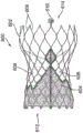
In embodiments, implantable medical devices useful in the present disclosure may be available under the trade name from Medtronic, inc Prosthetic valves are sold under the trade name evolout available from meiton force corporation TM Pro+ sold prosthetic valves, and the like. Non-limiting examples of implantable medical devices (e.g., implantable medical device 150) that may be used with the systems, devices, and methods of the present disclosure are shown in fig. 6A and 6B. In particular, fig. 6A shows a side view of a
 prosthetic heart valve 600 in a normal or expanded (uncompressed) arrangement. Fig. 6B shows the prosthetic heart valve 600 in a compressed arrangement (e.g., when held in compression within a delivery system, such as the distal portion 104 of the delivery system 100). Prosthetic heart valve 600 includes a stent or frame 602 and a valve structure 604. The stent 602 may take any of the forms described above, and is generally configured to be expandable from a compressed arrangement (fig. 6B) to an uncompressed arrangement (fig. 6A). In some embodiments, the stent 602 is self-expanding. In which it is arrangedIn other embodiments, the stent 602 is designed to be expanded to an expanded arrangement by a separate device (e.g., a balloon positioned inside the stent 602). The valve structure 604 is assembled to the stent 602 and provides two or more (typically three) leaflets 606. The valve structure 604 may be assembled to the stent 602 in various ways, such as by suturing the valve structure 604 to one or more of a wire segment or commissure posts defined by the stent 602.
The prosthetic heart valve 600 of fig. 6A and 6B may be configured to replace or repair an aortic valve. Alternatively, other shapes are also contemplated that are adapted to the particular anatomy of the valve to be repaired (e.g., a stented prosthetic heart valve according to the present disclosure may be shaped and/or sized for replacement of a native mitral valve, a pulmonary valve, or a tricuspid valve). In the example of fig. 6A and 6B, the valve structure 604 extends less than the entire length of the stent 602, but in other embodiments may extend along the entire length or nearly the entire length of the stent 602. A wide variety of other configurations are also acceptable and within the scope of the present disclosure. For example, the stent 602 may have a more cylindrical shape in a normal expanded arrangement.
The stent 602 includes a support structure that includes a plurality of struts or wire segments 608 that are arranged relative to one another to provide a desired compressibility and strength to the valve structure 604. The stent 602 may also include one or more paddles 610 that removably couple the prosthetic heart valve 600 to a delivery system (e.g., the delivery system 100). Although fig. 6A and 6B illustrate the blade 610, one skilled in the art will appreciate that the blade 610 may be replaced with other components such as a ferrule, ring, slot, or any other suitable coupling member. The paddle 610 (or other portion of the stent 602) may include one or more radiopaque markers that aid in the positioning and orientation of the prosthetic heart valve 600. The struts or wire portions 608 form a lumen having an inflow end 612 and an outflow end 614. The strut or wire portion 608 may be arranged such that the strut or wire portion 608 is capable of transitioning from a compressed arrangement to an uncompressed arrangement. The wires are arranged such that the scaffold 602 allows for folding or compressing or crimping into a compressed arrangement in which the inner diameter is smaller than when in an uncompressed arrangement. In the compressed configuration, such a stent 602 with attached valve structure 604 may be mounted to a delivery system, such as the distal portion 104 of the delivery system 100. The stents 602 are configured such that they can be changed to an uncompressed arrangement when desired, such as by relative movement of one or more sheaths relative to the length of the stent 602.
In embodiments, the strut or wire portion 608 of the stent 602 may be formed of a metal or other material that is expandable from a compressed arrangement to an uncompressed arrangement by an expansion device (e.g., balloon). In some embodiments, the wires of the support structure of the stent 602 in embodiments of the present disclosure may be formed from a shape memory material such as a nitinol (e.g., nitinol). With such materials, the support structure self-expands from the compressed arrangement to the normally expanded arrangement, such as by application of heat, energy, or the like, or by removal of an external force (e.g., a compressive force). The stent 602 may also be compressed and re-expanded multiple times without significantly damaging the structure of the stent 602. In addition, the stent 602 of this embodiment may be laser cut from a single piece of material, or may be assembled from a plurality of different components, or manufactured by various other methods known in the art.
In embodiments, the stent 602 may include an interior region in which the leaflets 606 may be secured. The leaflets 606 can be formed of a variety of materials, such as autologous tissue, xenograft material, or synthetic material as known in the art. In some embodiments, the leaflets 606 can be provided as a homogenous biological valve structure, such as a porcine valve, a bovine valve, or a equine valve. In some embodiments, the leaflets 606 can be provided independently of each other and subsequently assembled to the support structure of the stent 602. In some embodiments, the stent 602 and leaflet 606 can be fabricated simultaneously, such as can be accomplished using high strength nanofabricated NiTi films produced, for example, on advanced bioprosthetic surfaces (ABPS). The stent 602 may be configured to accommodate at least two (typically three) leaflets 606, but may incorporate more or less than three leaflets 606.
It should be understood that the various embodiments disclosed herein may be combined in different combinations than specifically presented in the specification and drawings. It should also be appreciated that certain acts or events of any of the processes or methods described herein can be performed in a different order, may be added, combined, or omitted entirely, depending on the example (e.g., not all of the described acts or events may be required to perform the techniques). Additionally, although certain aspects of the present disclosure are described as being performed by a single device or component for clarity, it should be understood that the techniques of the present disclosure may be performed by a combination of devices or components associated with, for example, medical devices.
Claims (21)
1. A system for delivering an implantable medical device to an implantation site, the system comprising:
a control handle portion;
a catheter portion coupled to the control handle portion at a proximal end of the catheter portion, the catheter portion comprising an outer shaft, wherein the outer shaft comprises:
a plurality of segments arranged in an axial direction to form the outer shaft of the catheter portion, each segment of the plurality of segments configured to move relative to one another; and
A distal portion coupled to a distal end of the outer shaft, the distal portion configured to receive the implantable medical device.
2. The system of claim 1, wherein the catheter section further comprises:
an inner shaft extending from the control handle portion through an interior of the plurality of segments to the distal portion.
3. The system of claim 2, wherein each of the plurality of segments comprises:
a ball portion having a spherical shape; and
a socket portion coupled to the ball portion by a neck portion, wherein the ball portion of one of the plurality of segments is configured to engage a socket portion of an adjacent segment of the plurality of segments.
4. The system of claim 3, wherein the neck portion and the ball portion define an inner channel, and wherein the inner channel of each of the plurality of segments forms an axial lumen for receiving the inner shaft when the plurality of segments are mated.
5. The system of claim 4, wherein a proximal opening of the inner channel formed in the ball portion has a larger cross-sectional area relative to a distal opening formed in the neck portion.
6. A system according to claim 3, wherein the socket portion comprises:
a first leg extending distally from the neck portion; and
a second leg extending distally from the neck portion, wherein:
the first leg and the second leg are formed on opposite sides of each of the plurality of segments,
the first leg and the second leg are curved inward and
the first and second legs movably secure the ball portion of one of the plurality of segments when engaged with the socket portion of an adjacent one of the plurality of segments.
7. The system of claim 5, wherein the first leg comprises a skewed distal end and the second leg comprises a skewed distal end, and wherein the skewed distal end of the first leg and the skewed distal end of the second leg operate as a stop when one of the plurality of segments moves relative to an adjacent segment of the plurality of segments.
8. The system of claim 2, wherein each of the plurality of segments comprises:
a body portion having a proximal end and a distal end and forming a lumen therebetween, wherein the lumen of one of the plurality of segments is configured to receive the proximal end of an adjacent segment of the plurality of segments.
9. The system of claim 8, wherein the body portion includes a lip portion formed at the distal end, and wherein an outer surface of the body portion tapers from the lip portion to the proximal end.
10. The system of claim 9, wherein the inner cavity has a frustoconical shape and the lip portion has a circular cross-section.
11. The system of claim 8, wherein the catheter section further comprises:
a plurality of washers coupled to the inner shaft, wherein a washer of the plurality of washers is coupled between adjacent segments of the plurality of segments.
12. A catheter of a delivery system for delivering an implantable medical device to an implantation site, the catheter comprising:
an outer shaft comprising a plurality of segments arranged in an axial direction from a control handle portion of the delivery system to a distal portion of the delivery system, each of the plurality of segments configured to move relative to one another; and
an inner shaft extending from the control handle portion through an interior of the plurality of segments to the distal portion.
13. The catheter of claim 12, wherein each segment of the plurality of segments comprises:
A ball portion having a spherical shape; and
a socket portion coupled to the ball portion by a neck portion, wherein the ball portion of one of the plurality of segments is configured to engage a socket portion of an adjacent segment of the plurality of segments.
14. The catheter of claim 13, wherein the neck portion and the ball portion define an inner channel, and wherein the inner channel of each of the plurality of segments forms a lumen for the inner shaft when the plurality of segments are mated.
15. The catheter of claim 14, wherein a proximal opening of the inner channel formed in the ball portion has a larger cross-sectional area relative to a distal opening formed in the neck portion.
16. The catheter of claim 13, wherein the socket portion comprises:
a first leg extending from the neck portion away from the ball portion; and
a second leg extending from the neck portion away from the ball portion, wherein:
the first leg and the second leg are formed on opposite sides of each of the plurality of segments,
The first leg and the second leg are curved inward and
the first and second legs movably secure the ball portion of one of the plurality of segments when engaged with the socket portion of an adjacent one of the plurality of segments.
17. The catheter of claim 15, wherein the first leg comprises a skewed distal end and the second leg comprises a skewed distal end, and wherein the skewed distal end of the first leg and the skewed distal end of the second leg operate as a stop when one of the plurality of segments moves relative to an adjacent segment of the plurality of segments.
18. The catheter of claim 12, wherein each segment of the plurality of segments comprises:
a body portion having a proximal end and a distal end and forming a lumen therebetween, wherein the lumen of one of the plurality of segments is configured to receive the proximal end of an adjacent segment of the plurality of segments.
19. The catheter of claim 18, wherein the body portion includes a lip portion formed at the distal end, and wherein an outer surface of the body portion tapers from the lip portion to the proximal end.
20. The catheter of claim 19, wherein the lumen has a frustoconical shape and the lip portion has a circular cross-section.
21. The catheter of claim 18, wherein the catheter portion further comprises:
a plurality of washers coupled to the inner shaft, wherein a washer of the plurality of washers is coupled between adjacent segments of the plurality of segments.
Applications Claiming Priority (3)
| Application Number | Priority Date | Filing Date | Title |
|---|---|---|---|
| US202063080357P | 2020-09-18 | 2020-09-18 | |
| US63/080,357 | 2020-09-18 | ||
| PCT/US2021/049985 WO2022060645A1 (en) | 2020-09-18 | 2021-09-13 | Flexible shafts for medical device delivery systems |
Publications (1)
| Publication Number | Publication Date |
|---|---|
| CN116018174A true CN116018174A (en) | 2023-04-25 |
Family
ID=78080518
Family Applications (1)
| Application Number | Title | Priority Date | Filing Date |
|---|---|---|---|
| CN202180054343.4A Pending CN116018174A (en) | 2020-09-18 | 2021-09-13 | Flexible Shafts for Medical Device Delivery Systems |
Country Status (4)
| Country | Link |
|---|---|
| US (1) | US20230355385A1 (en) |
| EP (1) | EP4213773A1 (en) |
| CN (1) | CN116018174A (en) |
| WO (1) | WO2022060645A1 (en) |
Families Citing this family (3)
| Publication number | Priority date | Publication date | Assignee | Title |
|---|---|---|---|---|
| KR20220150321A (en) * | 2020-03-06 | 2022-11-10 | 에드워즈 라이프사이언시스 코포레이션 | Transmission device with nose cone with ball joint |
| WO2025160120A1 (en) * | 2024-01-23 | 2025-07-31 | Boston Scientific Scimed, Inc. | Replacement heart valve system, implant delivery system, and method of deploying a replacement heart valve implant |
| US20260002617A1 (en) * | 2024-07-01 | 2026-01-01 | Fortimedix Assets Ii B.V. | Method of manufacturing a tube with a playless hinge and device comprising such a tube |
Family Cites Families (4)
| Publication number | Priority date | Publication date | Assignee | Title |
|---|---|---|---|---|
| WO2007149841A2 (en) * | 2006-06-20 | 2007-12-27 | Aortx, Inc. | Torque shaft and torque drive |
| EP2474287A1 (en) * | 2011-01-11 | 2012-07-11 | Symetis Sa | Delivery catheter for stent-valve, and sub-assembly therefor |
| WO2018098015A1 (en) * | 2016-11-22 | 2018-05-31 | Boston Scientific Scimed, Inc. | Medical device shaft resistant to compression and/or tension |
| WO2019147504A1 (en) * | 2018-01-25 | 2019-08-01 | Cephea Valve Technologies, Inc. | Cardiac valve delivery devices and systems |
-
2021
- 2021-09-13 CN CN202180054343.4A patent/CN116018174A/en active Pending
- 2021-09-13 WO PCT/US2021/049985 patent/WO2022060645A1/en not_active Ceased
- 2021-09-13 US US18/245,890 patent/US20230355385A1/en active Pending
- 2021-09-13 EP EP21787184.7A patent/EP4213773A1/en active Pending
Also Published As
| Publication number | Publication date |
|---|---|
| EP4213773A1 (en) | 2023-07-26 |
| US20230355385A1 (en) | 2023-11-09 |
| WO2022060645A1 (en) | 2022-03-24 |
Similar Documents
| Publication | Publication Date | Title |
|---|---|---|
| EP3583918B1 (en) | System for retrograde pericardial release of a prosthetic heart valve | |
| EP2480167B1 (en) | Stented transcatheter prosthetic heart valve delivery system | |
| US8070800B2 (en) | Transcatheter heart valve prostheses | |
| EP3009103A1 (en) | Flexible catheters and methods of forming same | |
| CN116018174A (en) | Flexible Shafts for Medical Device Delivery Systems | |
| US12023246B2 (en) | Stented prosthesis delivery devices having steering capabilities and methods | |
| EP4114310B1 (en) | Delivery apparatus having nosecone with a ball joint | |
| US20240299164A1 (en) | Prosthetic valve delivery apparatus with strain relief nosecone | |
| US20240398555A1 (en) | Valve prosthesis and transcatheter delivery system | |
| EP4397280B1 (en) | Transfer sleeve for use with a medical device delivery system | |
| WO2022040118A1 (en) | Implantable frame and frame retaining mechanism | |
| US20250295490A1 (en) | Transcatheter delivery device having flexible capsule | |
| CN118251195A (en) | Valve prostheses and transcatheter delivery systems | |
| US20230338142A1 (en) | Steerable delivery devices and systems for a stented prosthesis | |
| HK40086299B (en) | Delivery apparatus having nosecone with a ball joint | |
| HK40086299A (en) | Delivery apparatus having nosecone with a ball joint | |
| CN115734770A (en) | Delivery system for a prosthetic heart valve |
Legal Events
| Date | Code | Title | Description |
|---|---|---|---|
| PB01 | Publication | ||
| PB01 | Publication | ||
| SE01 | Entry into force of request for substantive examination | ||
| SE01 | Entry into force of request for substantive examination |