CN116122169A - Steel plate composite beam and construction method - Google Patents
Steel plate composite beam and construction method Download PDFInfo
- Publication number
- CN116122169A CN116122169A CN202310149094.8A CN202310149094A CN116122169A CN 116122169 A CN116122169 A CN 116122169A CN 202310149094 A CN202310149094 A CN 202310149094A CN 116122169 A CN116122169 A CN 116122169A
- Authority
- CN
- China
- Prior art keywords
- plate
- steel
- tire frame
- epoxy mortar
- bridge deck
- Prior art date
- Legal status (The legal status is an assumption and is not a legal conclusion. Google has not performed a legal analysis and makes no representation as to the accuracy of the status listed.)
- Granted
Links
Images


Classifications
-
- E—FIXED CONSTRUCTIONS
- E01—CONSTRUCTION OF ROADS, RAILWAYS, OR BRIDGES
- E01D—CONSTRUCTION OF BRIDGES, ELEVATED ROADWAYS OR VIADUCTS; ASSEMBLY OF BRIDGES
- E01D21/00—Methods or apparatus specially adapted for erecting or assembling bridges
-
- E—FIXED CONSTRUCTIONS
- E01—CONSTRUCTION OF ROADS, RAILWAYS, OR BRIDGES
- E01D—CONSTRUCTION OF BRIDGES, ELEVATED ROADWAYS OR VIADUCTS; ASSEMBLY OF BRIDGES
- E01D19/00—Structural or constructional details of bridges
- E01D19/06—Arrangement, construction or bridging of expansion joints
- E01D19/065—Joints having sliding plates
-
- E—FIXED CONSTRUCTIONS
- E01—CONSTRUCTION OF ROADS, RAILWAYS, OR BRIDGES
- E01D—CONSTRUCTION OF BRIDGES, ELEVATED ROADWAYS OR VIADUCTS; ASSEMBLY OF BRIDGES
- E01D19/00—Structural or constructional details of bridges
- E01D19/12—Grating or flooring for bridges; Fastening railway sleepers or tracks to bridges
- E01D19/125—Grating or flooring for bridges
-
- Y—GENERAL TAGGING OF NEW TECHNOLOGICAL DEVELOPMENTS; GENERAL TAGGING OF CROSS-SECTIONAL TECHNOLOGIES SPANNING OVER SEVERAL SECTIONS OF THE IPC; TECHNICAL SUBJECTS COVERED BY FORMER USPC CROSS-REFERENCE ART COLLECTIONS [XRACs] AND DIGESTS
- Y02—TECHNOLOGIES OR APPLICATIONS FOR MITIGATION OR ADAPTATION AGAINST CLIMATE CHANGE
- Y02A—TECHNOLOGIES FOR ADAPTATION TO CLIMATE CHANGE
- Y02A30/00—Adapting or protecting infrastructure or their operation
- Y02A30/60—Planning or developing urban green infrastructure
Landscapes
- Engineering & Computer Science (AREA)
- Architecture (AREA)
- Civil Engineering (AREA)
- Structural Engineering (AREA)
- Bridges Or Land Bridges (AREA)
- Conveying And Assembling Of Building Elements In Situ (AREA)
Abstract
本发明涉及一种钢板组合梁及施工方法,主梁拼接利用组拼式钢梁拼装胎架;预制桥面板钢筋绑扎利用组拼式钢筋胎架;采用可拆卸式桥面板快速支模体系;设置预制桥面板精确落位辅助装置;湿接缝钢筋设置定位装置;设置环氧砂浆精确铺设装置;采用自制的环氧砂浆刮平刀快速涂抹。本发明的有益效果是:本发明设置组拼式钢梁拼装胎架,现场拼装方便,将主梁间隔布置在侧向限位柱的钢梁限位槽内,提高了钢梁的组拼效率和组拼精度;利用横向梳齿板和纵向梳齿板对钢筋间距进行定位,有效降低了预制桥面板钢筋绑扎难度;设置预制桥面板落位辅助装置提高了预制桥面板的落位精度;设置环氧砂浆铺设装置,有效提高了环氧砂浆铺设精度和效率。

The invention relates to a steel plate composite girder and a construction method. The splicing of the main girder utilizes assembled steel beams to assemble tire frames; the binding of prefabricated bridge deck steel bars utilizes assembled type steel tire frames; a detachable bridge deck rapid formwork system is adopted; Prefabricated bridge deck accurate placement auxiliary device; wet joint reinforcement setting and positioning device; epoxy mortar precise laying device; self-made epoxy mortar scraper for quick application. The beneficial effects of the present invention are: the present invention is provided with assembled steel beams to assemble the tire frame, which is convenient for on-site assembly, and the main beams are arranged at intervals in the steel beam limit grooves of the lateral limit columns, which improves the assembly efficiency of steel beams and assembly accuracy; use horizontal and vertical combs to position the spacing of steel bars, which effectively reduces the difficulty of binding prefabricated bridge deck reinforcement; setting up prefabricated bridge deck positioning auxiliary devices improves the positioning accuracy of prefabricated bridge decks; setting The epoxy mortar laying device effectively improves the accuracy and efficiency of epoxy mortar laying.
Description
技术领域technical field
本发明涉及一种桥梁施工体系,尤其是涉及一种钢板组合梁及施工方法。The invention relates to a bridge construction system, in particular to a steel plate composite beam and a construction method.
背景技术Background technique
随着社会和经济的发展基于标准化、装配化以及信息化的建造技术已成为人们在进行民用建筑与交通设施建设时的首选。对于桥梁领域,采用基于预制拼装技术的桥梁快速建造技术是中小跨径桥梁建造的一种施工方法。钢板组合梁是使用预制桥面板和工字型钢梁组合形成的组合梁。钢板组合梁结构有助于节约工期,提升生产的机械化和工厂化,加快施工进度。但是,钢板组合梁在施工过程中也存在着许多难点,比如钢梁拼接难度大、湿接缝钢筋定位难、预制桥面模板体系重复利用率低及预制桥面板落位精度低等问题,需对钢板组合梁施工过程进行严格控制和提高。With the development of society and economy, construction technology based on standardization, assembly and informationization has become the first choice for people in the construction of civil buildings and transportation facilities. For the bridge field, the rapid construction technology of bridges based on prefabricated assembly technology is a construction method for small and medium-span bridges. Steel plate composite beam is a composite beam formed by combining prefabricated bridge deck and I-shaped steel beam. The steel plate composite beam structure helps to save the construction period, improve the mechanization and factoryization of production, and speed up the construction progress. However, there are many difficulties in the construction process of steel plate composite girders, such as the difficulty of splicing steel girders, the difficulty of positioning wet joint reinforcement, the low reuse rate of prefabricated bridge deck formwork systems, and the low positioning accuracy of prefabricated bridge decks. Strictly control and improve the construction process of steel plate composite beams.
综上所述,目前针对钢板组合梁施工体系,一种施工速度快、支模体系重复利用率高、预制桥面板落位精度高的钢板组合梁及施工方法显得十分重要。To sum up, for the steel plate composite girder construction system, a steel plate composite girder and construction method with fast construction speed, high reuse rate of the formwork system, and high positioning accuracy of the prefabricated bridge deck are very important.
发明内容Contents of the invention
本发明的目的是克服现有技术中的不足,提供一种钢板组合梁及施工方法。The purpose of the present invention is to overcome the deficiencies in the prior art, and provide a steel plate composite beam and a construction method.
这种钢板组合梁,包括:组拼式钢梁拼装胎架、组拼式钢筋胎架、可拆卸式桥面板快速支模体系、预制桥面板精确落位辅助装置、湿接缝钢筋设置定位装置、环氧砂浆精确铺设装置和环氧砂浆刮平刀;This kind of steel plate composite beam includes: assembled steel beam assembled tire frame, assembled steel tire frame, detachable bridge deck rapid formwork system, prefabricated bridge deck accurate positioning auxiliary device, wet joint steel bar setting and positioning device , Epoxy mortar precise laying device and epoxy mortar scraping knife;
组拼式钢梁拼装胎架包括侧向限位柱;侧向限位柱设于组拼式钢梁拼装胎架两侧,侧向限位柱上设有钢梁限位槽;The assembled steel beam assembled tire frame includes lateral limit columns; the lateral limit columns are arranged on both sides of the assembled steel beam assembled tire frame, and the lateral limit columns are provided with steel beam limit grooves;
组拼式钢筋胎架包括横向梳齿板和纵向梳齿板,横向梳齿板设有钢筋限位槽;横向梳齿板之间设有纵向梳齿板,纵向梳齿板上也设有钢筋限位槽;The assembled steel tire frame includes horizontal comb plates and longitudinal comb plates, and the horizontal comb plates are provided with steel bar limit grooves; between the horizontal comb plates, there are longitudinal comb plates, and the longitudinal comb plates are also provided with steel bars limit slot;
可拆卸式桥面板快速支模体系包括横向梳齿板、平板底膜、端模和楔形调节块,横向梳齿板和端模设于平板底膜四周,平板底膜上方焊接有楔形调节块;The detachable bridge deck rapid formwork system includes a transverse comb plate, a flat base film, an end form and a wedge-shaped adjustment block. The transverse comb plate and end form are arranged around the plate base film, and a wedge-shaped adjustment block is welded above the plate base film;
预制桥面板精确落位辅助装置包括限位槽和导向槽钢,限位槽与主梁固定连接;预制桥面板上固定连接导向槽钢;Prefabricated bridge deck accurate positioning auxiliary device includes limit groove and guide channel steel, the limit groove is fixedly connected with the main girder; the prefabricated bridge deck is fixedly connected with guide channel steel;
湿接缝钢筋设置定位装置包括上下开槽连接板;上下开槽连接板通过临时固定挂钩连接有压板;上下开槽连接板设有上层钢筋限位孔和底层钢筋限位孔。The setting and positioning device for the wet joint reinforcement includes an upper and lower slotted connecting plate; the upper and lower slotted connecting plate is connected with a pressure plate through a temporary fixing hook; the upper and lower slotted connecting plate is provided with upper and lower reinforcing bar limit holes.
作为优选:所述的组拼式钢梁拼装胎架,还包括胎架竖向支撑、胎架横向支撑、胎架斜支撑、直角连接件、斜撑固定板、托臂底架和固定螺栓;胎架竖向支撑底部焊接托臂底架,托臂底架通过固定螺栓与地面连接;胎架竖向支撑与胎架横向支撑通过直角连接件固定,直角连接件上设有固定螺栓;胎架竖向支撑与胎架横向支撑间还设有胎架斜支撑加强连接,胎架斜支撑两端分别通过斜撑固定板与胎架竖向支撑及胎架横向支撑固定;侧向限位柱与胎架横向支撑通过直角连接件固定。As a preference: the assembled steel beam assembled tire frame also includes tire frame vertical supports, tire frame lateral supports, tire frame diagonal supports, right-angle connectors, diagonal brace fixing plates, bracket arm bases and fixing bolts; The bottom of the vertical support of the tire frame is welded to the support arm base frame, and the support arm base frame is connected to the ground through fixing bolts; the vertical support of the tire frame and the horizontal support of the tire frame are fixed through right-angle connectors, and the right-angle connectors are equipped with fixing bolts; tire frame There is also a reinforced connection between the vertical support and the horizontal support of the tire frame, and the two ends of the diagonal support of the tire frame are respectively fixed by the diagonal brace fixing plate, the vertical support of the tire frame and the horizontal support of the tire frame; The lateral supports of the tire frame are fixed by right-angle connectors.
作为优选:所述的组拼式钢筋胎架,还包括支撑立柱、纵向梳齿板固定槽、横向支撑、胎架底板、纵向固定板和卡槽;胎架底板左右对称布置,胎架底板之间通过横向支撑加强连接;胎架底板与横向梳齿板间设有支撑立柱,支撑立柱通过直角连接件固定,直角连接件上设有固定螺栓;横向梳齿板上设有纵向梳齿板固定槽,左右两侧横向梳齿板上的纵向梳齿板固定槽对称布置,左右两侧横向梳齿板之间通过纵向固定板连接;纵向梳齿板上还设有卡槽,纵向梳齿板利用卡槽与纵向梳齿板固定槽固定连接。As a preference: the assembled steel tire frame also includes support columns, longitudinal comb-tooth plate fixing grooves, lateral supports, tire frame bottom plates, longitudinal fixing plates and card grooves; the tire frame bottom plates are symmetrically arranged left and right, The connection is strengthened by transverse support; there is a support column between the bottom plate of the tire frame and the transverse comb plate, and the support column is fixed by a right-angle connector, and a fixing bolt is arranged on the right-angle connector; a longitudinal comb plate is fixed on the transverse comb plate Slots, the fixed grooves of the longitudinal comb plates on the horizontal comb plates on the left and right sides are symmetrically arranged, and the horizontal comb plates on the left and right sides are connected by vertical fixing plates; there are also card slots on the longitudinal comb plates. Utilize the draw-in groove to be fixedly connected with the fixing groove of the longitudinal comb tooth plate.
作为优选:所述的可拆卸式桥面板快速支模体系,还包括斜撑固定板、固定螺栓、底模竖向支撑、底膜侧向支撑和底膜斜撑;平板底膜下方通过底模竖向支撑与地面固定,横向梳齿板底部通过固定螺栓与平板底膜连接固定;端模底部通过固定螺栓与平板底膜连接固定;横向梳齿板与平板底膜间通过底膜侧向支撑和底膜斜撑加强连接,底膜斜撑两端分别焊接有斜撑固定板,斜撑固定板通过固定螺栓连接横向梳齿板或底膜侧向支撑。As a preference: the detachable bridge deck rapid formwork support system also includes a diagonal brace fixing plate, a fixing bolt, a bottom mold vertical support, a bottom film lateral support and a bottom film diagonal brace; the bottom film passes through the bottom mold The vertical support is fixed to the ground, the bottom of the horizontal comb plate is connected and fixed with the flat bottom film by fixing bolts; the bottom of the end mold is connected and fixed with the flat bottom film by fixing bolts; the horizontal comb plate and the flat bottom film are laterally supported by the bottom film It is connected with the diagonal brace of the bottom film, and the two ends of the diagonal brace of the bottom film are respectively welded with a diagonal brace fixing plate, and the diagonal brace fixing plate is connected to the horizontal comb plate or the lateral support of the bottom membrane through fixing bolts.
作为优选:所述的预制桥面板精确落位辅助装置,还包括固定螺栓、竖向限位板、固定连接板和横向限位板组成;竖向限位板左右对称设于横向限位板两端,横向限位板中间设有限位槽;竖向限位板一侧焊接有固定连接板,固定连接板通过固定螺栓与主梁连接;预制桥面板上通过固定螺栓固定连接导向槽钢,导向槽钢落位于限位槽中。As a preference: the prefabricated bridge deck accurate positioning auxiliary device also includes fixing bolts, vertical limiting plates, fixed connecting plates and transverse limiting plates; the vertical limiting plates are symmetrically arranged on both sides of the horizontal limiting plates There is a limit groove in the middle of the horizontal limit plate; a fixed connection plate is welded on one side of the vertical limit plate, and the fixed connection plate is connected to the main beam through fixing bolts; The channel steel falls in the limiting groove.
作为优选:所述的湿接缝钢筋设置定位装置,还包括预留挂钩孔;上下开槽连接板上通过预留挂钩孔安装有临时固定挂钩,临时固定挂钩上端与压板连接;上下开槽连接板顶部和底部分别设有上层钢筋限位孔和底层钢筋限位孔。As a preference: the positioning device for setting the wet joint steel bar also includes a reserved hook hole; a temporary fixing hook is installed on the upper and lower slotted connecting plate through the reserved hook hole, and the upper end of the temporary fixing hook is connected with the pressure plate; the upper and lower slotting connection The top and the bottom of the plate are respectively provided with upper-layer steel bar limit holes and bottom-layer steel bar limit holes.
作为优选:所述的环氧砂浆精确铺设装置,包括位移调节轴、滑轨、滑块、滑轨支撑柱、槽钢直角连接件、环氧砂浆和滑轨固定板;滑轨支撑柱左右两侧对称布置,滑轨支撑柱下端设有槽钢直角连接件,槽钢直角连接件通过固定螺栓与横梁连接;滑轨固定板与滑轨支撑柱通过螺栓固定,滑轨固定板上设有滑轨;滑轨上间隔布置有位移调节轴,位移调节轴通过滑块与滑轨连接。As a preference: the epoxy mortar precise laying device includes a displacement adjustment shaft, a slide rail, a slider, a slide rail support column, a channel steel right-angle connector, epoxy mortar and a slide rail fixing plate; the left and right sides of the slide rail support column The side is symmetrically arranged, the lower end of the slide rail support column is provided with a channel steel right-angle connector, and the channel steel right-angle connector is connected to the beam through fixing bolts; the slide rail fixing plate and the slide rail support column are fixed by bolts, and the slide rail fixing plate is provided with a slide Rails; displacement adjustment shafts are arranged at intervals on the slide rails, and the displacement adjustment shafts are connected to the slide rails through sliders.
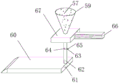
作为优选:所述的环氧砂浆刮平刀,包括环氧砂浆储存槽、刀片、环氧砂浆输出口、环氧砂浆输送管、阀门连接杆、阀门开闭板、阀门、把手和支撑板;支撑板一侧焊接有把手,支撑板上方设有环氧砂浆储存槽,环氧砂浆储存槽内存放有环氧砂浆;环氧砂浆输送管上端与环氧砂浆储存槽底部连接,下端与刀片平齐;环氧砂浆输送管内部设有阀门开闭板,阀门开闭板利用阀门连接杆与阀门连接,阀门转动时调节阀门开闭板的角度随之变化。As a preference: the epoxy mortar scraper includes an epoxy mortar storage tank, a blade, an epoxy mortar output port, an epoxy mortar delivery pipe, a valve connecting rod, a valve opening and closing plate, a valve, a handle and a support plate; There is a handle welded on one side of the support plate, and there is an epoxy mortar storage tank above the support plate, and epoxy mortar is stored in the epoxy mortar storage tank; the upper end of the epoxy mortar delivery pipe is connected with the bottom of the epoxy mortar storage tank, and the lower end is flat with the blade. Qi; The epoxy mortar conveying pipe is equipped with a valve opening and closing plate inside, and the valve opening and closing plate is connected with the valve by a valve connecting rod. When the valve rotates, the angle of the valve opening and closing plate is adjusted to change accordingly.
这种钢板组合梁的施工方法,包括以下步骤:The construction method of this steel plate composite beam comprises the following steps:
步骤一、利用组拼式钢梁拼装胎架进行钢板组合梁拼装:安装组拼式钢梁拼装胎架,主梁间隔布置在侧向限位柱的钢梁限位槽内;在相邻主梁之间焊接横梁,拼装钢板组合梁;
步骤二、钢板组合梁吊装施工:采用单根纵梁整跨逐个吊装法,利用汽车吊进行吊装,钢板组合梁纵梁吊装次序为:内边梁、中梁、中梁、外边梁;
步骤三、钢筋绑扎:安装组拼式钢筋胎架,利用横向梳齿板和纵向梳齿板对钢筋间距进行定位,进行预制桥面板的钢筋绑扎;
步骤四、钢筋骨架入模及桥面板浇筑:安装可拆卸式桥面板支模体系后,将横向钢筋和横向梳齿板对准下放,使钢筋骨架入模;浇筑预制桥面板;Step 4: Molding of the reinforcement skeleton and pouring of the bridge deck: After installing the detachable bridge deck formwork system, align and lower the horizontal reinforcement and the horizontal comb plate to make the reinforcement skeleton into the mold; pour the prefabricated bridge deck;
步骤五、环氧砂浆铺设:安装环氧砂浆铺设装置,利用滑块调节位移调节轴的位置,实现环氧砂浆的精确铺设;并采用环氧砂浆刮平刀辅助摊铺;通过阀门调节环氧砂浆的输送;
步骤六、桥面板精确落位:利用预制桥面板精确落位辅助装置,通过吊装桥面板使导向槽钢落位限位槽;
步骤七、湿接缝施工:安装湿接缝钢筋设置定位装置,湿接缝钢筋定位后,湿接缝模板采用钢索和压板固定后,进行混凝土的浇注。
作为优选,步骤七中:采用竹胶板作为湿接缝的底模,钢索上设有塑料套筒,压板两端设有固定连接板;预制桥面板上设有预埋定位板,预埋定位板上设有预埋插杆,预埋定位板通过固定螺栓与固定连接板连接;钢筋和模板验收合格后进行混凝土的浇注;混凝土采用汽车吊配合料斗进行浇筑,使用插入式振捣器,先四周后中部、快插慢拔地进行振捣,混凝土施工完毕后,覆盖塑料薄膜。Preferably, in step seven: use bamboo plywood as the bottom mold of the wet joint, plastic sleeves are provided on the steel cables, fixed connecting plates are provided at both ends of the pressing plate; prefabricated bridge decks are provided with pre-embedded positioning plates, There is a pre-embedded insertion rod on the positioning plate, and the pre-embedded positioning plate is connected to the fixed connecting plate through fixing bolts; the concrete is poured after the steel bars and formwork are accepted; the concrete is poured with a truck crane and a hopper, and a plug-in vibrator is used Vibrate first four weeks and then in the middle, with quick insertion and slow removal. After the concrete construction is completed, cover it with plastic film.
本发明的有益效果是:The beneficial effects of the present invention are:
1)本发明设置组拼式钢梁拼装胎架,现场拼装方便,将主梁间隔布置在侧向限位柱的钢梁限位槽内,提高了钢梁的组拼效率和组拼精度。1) The present invention is equipped with assembled steel beams to assemble the tire frame, which is convenient for on-site assembly, and the main beams are arranged at intervals in the steel beam limit grooves of the lateral limit columns, which improves the assembly efficiency and accuracy of the steel beams.
2)本发明设置组拼式钢筋胎架,利用横向梳齿板和纵向梳齿板对钢筋间距进行定位,有效降低了预制桥面板钢筋绑扎难度。2) The present invention is provided with assembled steel tire frames, and utilizes transverse and longitudinal combs to position the distance between the steel bars, which effectively reduces the difficulty of binding the steel bars on the prefabricated bridge deck.
3)本发明采用可拆卸式桥面板快速支模体系,在平板底膜四周设置横向梳齿板和端模,平板底膜上方焊接有楔形调节块,提高了变截面桥面板的预制效率。3) The present invention adopts a detachable rapid formwork system for bridge decks. Horizontal comb plates and end molds are arranged around the flat bottom membrane, and wedge-shaped adjustment blocks are welded above the flat bottom membrane, which improves the prefabrication efficiency of variable-section bridge decks.
4)本发明设置预制桥面板落位辅助装置,设有匹配的导向槽钢和限位槽,提高了预制桥面板的落位精度。4) The present invention is equipped with a prefabricated bridge deck placement auxiliary device, and is equipped with a matching guide channel steel and a limit groove, which improves the placement accuracy of the prefabricated bridge deck.
5)本发明设置湿接缝钢筋定位装置,通过在上下端分别开有上层钢筋限位孔和底层钢筋限位孔的上下开槽连接板,有效降低了湿接缝钢筋安装的难度。5) The present invention is equipped with a wet joint reinforcing bar positioning device, and effectively reduces the difficulty of wet joint reinforcing bar installation through upper and lower slotted connecting plates with upper and lower reinforcing bar limit holes respectively opened at the upper and lower ends.
6)本发明设置环氧砂浆铺设装置,利用滑块调节位移调节轴的位置,实现环氧砂浆的精确铺设,有效提高了环氧砂浆铺设精度和效率。6) The present invention is equipped with an epoxy mortar laying device, and uses a slider to adjust the position of the displacement adjustment axis to realize precise laying of epoxy mortar, effectively improving the precision and efficiency of epoxy mortar laying.
7)本发明采用自制的环氧砂浆刮平刀,通过阀门调节环氧砂浆的输送,并设有与环氧砂浆输送管下端平齐的刀片,可大幅提升环氧砂浆涂抹速度。7) The present invention adopts a self-made epoxy mortar scraper, adjusts the transmission of epoxy mortar through a valve, and is equipped with a blade flush with the lower end of the epoxy mortar delivery pipe, which can greatly increase the speed of epoxy mortar application.
附图说明Description of drawings
图1是组拼式钢梁拼装胎架结构示意图;Fig. 1 is a structural schematic diagram of assembled steel beam assembled tire frame;
图2是钢梁组拼结构示意图;Fig. 2 is a structural schematic diagram of steel beam assembly;
图3是钢梁拼装完成结构示意图;Fig. 3 is a structural schematic diagram of steel girder assembly;
图4是组拼式钢筋胎架结构示意图;Fig. 4 is a structural schematic diagram of assembled type reinforced tire frame;
图5是纵向梳齿板结构示意图;Fig. 5 is a structural schematic diagram of a longitudinal comb tooth plate;
图6是可拆卸式桥面板快速支模体系结构示意图;Figure 6 is a schematic diagram of the detachable bridge deck quick formwork system;
图7是预制桥面板安装结构示意图;Figure 7 is a schematic diagram of the installation structure of the prefabricated bridge deck;
图8是可预制桥面板落位辅助装置结构示意图;Fig. 8 is a structural schematic diagram of a prefabricated bridge deck placement auxiliary device;
图9是湿接缝施工结构示意图;Fig. 9 is a schematic diagram of wet joint construction structure;
图10是湿接缝钢筋定位装置结构示意图;Fig. 10 is a structural schematic diagram of a wet joint reinforcing bar positioning device;
图11是钢索结构示意图;Fig. 11 is a schematic diagram of a steel cable structure;
图12是预埋定位板与固定连接件锚固示意图;Figure 12 is a schematic diagram of the anchoring of the embedded positioning plate and the fixed connector;
图13是环氧砂浆铺设装置结构示意图;Fig. 13 is the structural representation of epoxy mortar laying device;
图14是自制的环氧砂浆刮平刀结构示意图。Figure 14 is a schematic diagram of the structure of a self-made epoxy mortar scraper.
图中:1-组拼式钢梁拼装胎架,2-胎架竖向支撑,3-胎架横向支撑,4-胎架斜支撑,5-钢梁限位槽,6-直角连接件,7-斜撑固定板,8-托臂底架,9-固定螺栓,10-侧向限位柱,11-剪力钉,12-竖向加劲肋,13-主梁,14-横梁,15-组拼式钢筋胎架,16-支撑立柱,17-横向梳齿板,18-纵向梳齿板固定槽,19-横向支撑,20-钢筋限位槽,21-胎架底板,22-纵向固定板,23-纵向梳齿板,24-卡槽,25-平板底膜,26-底模竖向支撑,27-底膜侧向支撑,28-底膜斜撑,29-端模,30-楔形调节块,31-竖向限位板,32-限位槽,33-固定连接板,34-横向限位板,35-导向槽钢,36-预制桥面板,37-预埋湿接缝钢筋,38-压板,39-钢索,40-临时固定钢挂钩,41-底层钢筋,42-上层钢筋,43-塑料套筒,44-湿接缝底面模板,45-上下开槽连接板,46-固定连接板,47-上层钢筋限位孔,48-预留挂钩孔,49-底层钢筋限位孔,50-,预埋定位板,51-预埋插杆,52-位移调节轴,53-滑轨,54-滑块,55-滑轨支撑柱,56-槽钢直角连接件,57-环氧砂浆,58-滑轨固定板,59-环氧砂浆储存槽,60-刀片,61-环氧砂浆输出口,62-环氧砂浆输送管,63-阀门连接杆,64-阀门开闭板,65-阀门,66-把手,67-支撑板。In the figure: 1-assembled steel beam assembled tire frame, 2-vertical support of tire frame, 3-horizontal support of tire frame, 4-oblique support of tire frame, 5-limiting groove of steel beam, 6-right-angle connector, 7-Slant bracing fixing plate, 8-Bracket base frame, 9-Fixing bolt, 10-Lateral limit column, 11-Shear nail, 12-Vertical stiffener, 13-Main beam, 14-Beam, 15 - Assembled steel tire frame, 16-support column, 17-horizontal comb plate, 18-longitudinal comb plate fixing groove, 19-horizontal support, 20-rebar limit groove, 21-frame base plate, 22-longitudinal Fixed plate, 23-longitudinal comb plate, 24-card slot, 25-flat bottom film, 26-bottom mold vertical support, 27-bottom film lateral support, 28-bottom film diagonal brace, 29-end mold, 30 -Wedge-shaped adjustment block, 31-vertical limit plate, 32-limit slot, 33-fixed connecting plate, 34-transverse limit plate, 35-guiding channel steel, 36-prefabricated bridge deck, 37-embedded wet joint Seam reinforcement, 38-pressure plate, 39-steel cable, 40-temporary fixed steel hook, 41-bottom reinforcement, 42-upper reinforcement, 43-plastic sleeve, 44-wet joint bottom formwork, 45-up and down grooved connecting plate ,46-fixed connecting plate,47-limiting hole for upper steel bar, 48-reserved hook hole, 49-limiting hole for bottom steel bar, 50-, embedded positioning plate, 51-embedded insertion rod, 52-displacement adjustment shaft ,53-Slide rail,54-Slider block,55-Slide rail support column,56-Channel steel right-angle connector,57-Epoxy mortar,58-Slide rail fixing plate,59-Epoxy mortar storage tank,60-Blade , 61-epoxy mortar output port, 62-epoxy mortar delivery pipe, 63-valve connecting rod, 64-valve opening and closing plate, 65-valve, 66-handle, 67-support plate.
具体实施方式Detailed ways
下面结合实施例对本发明做进一步描述。下述实施例的说明只是用于帮助理解本发明。应当指出,对于本技术领域的普通人员来说,在不脱离本发明原理的前提下,还可以对本发明进行若干修饰,这些改进和修饰也落入本发明权利要求的保护范围内。The present invention will be further described below in conjunction with the examples. The description of the following examples is provided only to aid the understanding of the present invention. It should be pointed out that for those skilled in the art, some modifications can be made to the present invention without departing from the principles of the present invention, and these improvements and modifications also fall within the protection scope of the claims of the present invention.
实施例一Embodiment one
作为一种实施例,如图1至图14所示,这种钢板组合梁体系,包括组拼式钢梁拼装胎架1、胎架竖向支撑2、胎架横向支撑3、胎架斜支撑4、钢梁限位槽5、直角连接件6、斜撑固定板7、托臂底架8、固定螺栓9、侧向限位柱10、剪力钉11,竖向加劲肋12、主梁13、横梁14、组拼式钢筋胎架15,支撑立柱16,横向梳齿板17,纵向梳齿板固定槽18,横向支撑19,钢筋限位槽20、胎架底板21、纵向固定板22、纵向梳齿板23,卡槽24、平板底膜25、底模竖向支撑26,底膜侧向支撑27、底膜斜撑28、端模29、楔形调节块30、竖向限位板31、限位槽32、固定连接板33,横向限位板34,导向槽钢35,预制桥面板36,预埋湿接缝钢筋37,压板38,钢索39,临时固定钢挂钩40,底层钢筋41、上层钢筋42、塑料套筒43、湿接缝底面模板44、上下开槽连接板45,固定连接板46,上层钢筋限位孔47、预留挂钩孔48、底层钢筋限位孔49、预埋定位板50、预埋插杆51、位移调节轴52,滑轨53,滑块54,滑轨支撑柱55,槽钢直角连接件56,环氧砂浆57,滑轨固定板58、环氧砂浆储存槽59、刀片60、环氧砂浆输出口61、环氧砂浆输送管62,阀门连接杆63、阀门开闭板64、阀门65、把手66、支撑板67;主梁13拼接利用组拼式钢梁拼装胎架1;预制桥面板36钢筋绑扎利用组拼式钢筋胎架15;采用可拆卸式桥面板快速支模体系;设置预制桥面板36精确落位辅助装置;湿接缝钢筋设置定位装置;设置环氧砂浆57精确铺设装置;采用自制的环氧砂浆刮平刀快速涂抹。As an example, as shown in Figure 1 to Figure 14, this steel plate composite beam system includes assembled steel beam assembled
所述的组拼式钢梁拼装胎架1,由胎架竖向支撑2、胎架横向支撑3、胎架斜支撑4、钢梁限位槽5、直角连接件6、斜撑固定板7、托臂底架8、固定螺栓9和侧向限位柱10组成;胎架竖向支撑2底部焊接托臂底架8,设置固定螺栓9与地面连接;胎架竖向支撑2与胎架横向支撑3通过直角连接件6固定,直角连接件6上设有固定螺栓9;胎架竖向支撑2与胎架横向支撑3间还设置胎架斜支撑4加强连接,胎架斜支撑4两端分别焊接斜撑固定板7与胎架竖向支撑2及胎架横向支撑3固定;侧向限位柱10上设置钢梁限位槽5,与胎架横向支撑3通过直角连接件6固定。The assembled steel beam assembled
所述的组拼式钢筋胎架15,由支撑立柱16、横向梳齿板17、纵向梳齿板固定槽18、横向支撑19、钢筋限位槽20、胎架底板21、纵向固定板22、纵向梳齿板23和卡槽24组成;胎架底板21左右对称布置,通过横向支撑19加强连接;横向梳齿板17上设置钢筋限位槽20;胎架底板21与横向梳齿板17间设置支撑立柱16,通过直角连接件6固定,直角连接件6上设有固定螺栓9;横向梳齿板17上设置纵向梳齿板固定槽18,左右两侧对称布置,通过纵向固定板22加强连接;纵向梳齿板23上设置钢筋限位槽20和卡槽24,利用卡槽24与纵向梳齿板固定槽18固定连接。The assembled
所述的可拆卸式桥面板快速支模体系,由斜撑固定板7、固定螺栓9、横向梳齿板17、平板底膜25、底模竖向支撑26、底膜侧向支撑27、底膜斜撑28、端模29和楔形调节块30组成;平板底膜25下方设置底模竖向支撑26与地面固定,上方焊接楔形调节块30;通过横向梳齿板17底部固定螺栓9与平板底膜25连接固定;端模29底部固定螺栓9与平板底膜25连接固定;横向梳齿板17与平板底膜25间设置底膜侧向支撑27和底膜斜撑28加强连接,底膜斜撑28两端分别焊接斜撑固定板7,通过固定螺栓9与横向梳齿板17和底膜侧向支撑27连接。The detachable bridge deck rapid formwork support system consists of a diagonal
所述的预制桥面板精确落位辅助装置,由固定螺栓9、竖向限位板31、限位槽32、固定连接板33、横向限位板34和导向槽钢35组成;竖向限位板31和横向限位板34通过焊接加工而成,左右对称设置,中间设置限位槽32;竖向限位板31一侧焊接固定连接板33,通过固定螺栓9与主梁13连接;预制桥面板36上通过固定螺栓9固定连接导向槽钢35,通过导向槽钢35落位限位槽32实现预制桥面板36精确定位。The prefabricated bridge deck accurate placement auxiliary device is composed of a fixing
所述的湿接缝钢筋设置定位装置,由临时固定挂钩40、上下开槽连接板45、上层钢筋限位孔47、预留挂钩孔48和底层钢筋限位孔49组成;上下开槽连接板45上设置预留挂钩孔48安装临时固定挂钩40,通过临时固定挂钩40与压板38连接;上下开槽连接板45顶部和底部分别设置上层钢筋限位孔47及底层钢筋限位孔49,实现湿接缝钢筋精确定位。The positioning device for the wet joint reinforcing bar is composed of a
所述的环氧砂浆57精确铺设装置,由位移调节轴52、滑轨53、滑块54、滑轨支撑柱55、槽钢直角连接件56、环氧砂浆57和滑轨固定板58组成;滑轨支撑柱55左右两侧对称布置,下端设置槽钢直角连接件56通过固定螺栓9与横梁14连接;滑轨固定板58与滑轨支撑柱55通过螺栓固定,其上设置滑轨53;滑轨上间隔布置位移调节轴52,通过滑块54与滑轨53连接,利用滑块54调节位移调节轴52的位置,实现环氧砂浆57的精确铺设。The
所述的环氧砂浆刮平刀,由环氧砂浆储存槽59、刀片60、环氧砂浆输出口61、环氧砂浆输送管62、阀门连接杆63、阀门开闭板64、阀门65、把手66和支撑板67组成;支撑板67右侧焊接把手66,上方设置环氧砂浆储存槽59存放环氧砂浆57;环氧砂浆输送管62上端与环氧砂浆储存槽59底部连接,下端与刀片60平齐;环氧砂浆输送管62内部设置阀门开闭板64,利用阀门连接杆63与阀门65连接,通过转动阀门65调节阀门开闭板64的角度,实现环氧砂浆57的输送。The epoxy mortar scraping knife is composed of epoxy
实施例二Embodiment two
作为另一种实施例,本实施例中给出了实施例一所述的钢板组合梁的施工方法,其主要施工步骤如下:As another embodiment, the construction method of the steel plate composite beam described in
步骤一、钢梁运输:钢结构单元件厂内制作完毕后,采用公路运输至桥位架设场地,在组拼式钢梁拼装胎架1上进行钢梁的拼装接长及安装架设。
组拼式钢梁拼装胎架安装:组拼式钢梁拼装胎架1由胎架竖向支撑2、胎架横向支撑3、胎架斜支撑4、钢梁限位槽5、直角连接件6、斜撑固定板7、托臂底架8、固定螺栓9和侧向限位柱10组成;胎架竖向支撑2底部焊接托臂底架8,设置固定螺栓9与地面连接;胎架竖向支撑2与胎架横向支撑3通过直角连接件6固定,直角连接件6上设有固定螺栓9;胎架竖向支撑2与胎架横向支撑3间还设置胎架斜支撑4加强连接,胎架斜支撑4两端分别焊接斜撑固定板7与胎架竖向支撑2及胎架横向支撑3固定;侧向限位柱10上设置钢梁限位槽5,与胎架横向支撑3通过直角连接件6固定。预制的主梁13上设有竖向加劲肋12和剪力钉11,主梁13间隔布置在侧向限位柱10的钢梁限位槽5内;在相邻主梁13之间焊接横梁14。Assembled steel beam assembled tire frame installation: Assembled steel beam assembled
步骤二、钢板组合梁吊装施工:钢板组合梁现场拼装完成后,采用单根纵梁整跨逐个吊装法,利用汽车吊进行吊装,钢板组合梁纵梁吊装次序为:内边梁→中梁→中梁→外边梁。
步骤三、组拼式钢筋胎架安装:组拼式钢筋胎架15由支撑立柱16、横向梳齿板17、纵向梳齿板固定槽18、横向支撑19、钢筋限位槽20、胎架底板21、纵向固定板22、纵向梳齿板23和卡槽24组成;胎架底板21左右对称布置,通过横向支撑19加强连接;横向梳齿板17上设置钢筋限位槽20;胎架底板21与横向梳齿板17间设置支撑立柱16,通过直角连接件6固定,直角连接件6上设有固定螺栓9;横向梳齿板17上设置纵向梳齿板固定槽18,左右两侧对称布置,通过纵向固定板22加强连接;纵向梳齿板23上设置钢筋限位槽20和卡槽24,利用卡槽24与纵向梳齿板固定槽18固定连接。Step 3: Installation of assembled steel bar frame: assembled
钢筋绑扎:组拼式钢筋胎架15安装完成后,利用梳齿板对钢筋间距进行定位,进行预制桥面板36的钢筋绑扎,钢筋的绑扎要满足桥梁的施工要求。Reinforcement binding: After the assembly-
步骤四、可拆卸式桥面板支模体系制作与安装:可拆卸式桥面板快速支模体系为平板底模25+楔形调节块30+梳齿板、端模29的组合体系,只按照图纸调整楔形调节块30、端模29的位置来改变预制桥面板36的尺寸。可拆卸式桥面板快速支模体系平板底膜25下方设置底模竖向支撑26与地面固定,上方焊接楔形调节块30;通过横向梳齿板17底部固定螺栓9与平板底膜25连接固定;端模29底部固定螺栓9与平板底膜25连接固定;横向梳齿板17与平板底膜25间设置底膜侧向支撑27和底膜斜撑28加强连接,底膜斜撑28两端分别焊接斜撑固定板7,通过固定螺栓9与横向梳齿板17和底膜侧向支撑27连接。
钢筋骨架入模:钢筋绑扎完成后,采用专用钢筋吊装吊具,缓慢吊至模板上方,通过位置调整对其横向钢筋和梳齿板的空隙对准,再缓慢下放钢筋,使钢筋骨架缓慢入模,入模过程中如有钢筋与模板存在冲突位置,应及时调整部分钢筋间距,使其顺利入模,再恢复;入模完成后,安装横向预应力管道。Reinforcement skeleton into the mold: After the reinforcement is bound, use a special reinforcement hoisting sling to slowly lift it to the top of the formwork, adjust the position to align the horizontal reinforcement and the gap between the comb plate, and then slowly lower the reinforcement to make the reinforcement skeleton slowly enter the mold , If there is a conflict between the steel bar and the formwork during the mold entry process, the spacing of some steel bars should be adjusted in time to make it enter the mold smoothly, and then restore it; after the mold entry is completed, install the transverse prestressed pipe.
桥面板混凝土浇筑及养护:为保证预制桥面板36混凝土内在及外观质量,波纹管以下先以Φ30振捣棒振捣,波纹管以上用Φ50振捣棒振捣。振捣器不得碰撞模板、波纹管和其他预埋件。混凝土养护采用表面覆膜洒水保湿养护方式。Concrete pouring and maintenance of the bridge deck: In order to ensure the inner and appearance quality of the
张拉与压浆:钢束采用单端交错张拉,依次交错张拉钢束,单端张拉,分级逐步加载;压浆前使用空压机对孔道进行清洁处理,采用智能压浆设备进行压浆,同一管道的压浆应连续进行,一次完成。Tensioning and grouting: the steel strands are stretched in a single-end staggered manner, and the steel strands are staggered in turn, single-end tensioned, and loaded step by step; before the grouting, the air compressor is used to clean the tunnels, and the intelligent grouting equipment is used for cleaning. Grouting, the grouting of the same pipeline should be carried out continuously and completed at one time.
步骤五、环氧砂浆铺设:环氧砂浆57铺设时安装环氧砂浆铺设装置装置,由位移调节轴52、滑轨53、滑块54、滑轨支撑柱55、槽钢直角连接件56、环氧砂浆57和滑轨固定板58组成;滑轨支撑柱55左右两侧对称布置,下端设置槽钢直角连接件56通过固定螺栓9与横梁14连接;滑轨固定板58与滑轨支撑柱55通过螺栓固定,其上设置滑轨53;滑轨上间隔布置位移调节轴52,通过滑块54与滑轨53连接,利用滑块54调节位移调节轴52的位置,实现环氧砂浆57的精确铺设;环氧砂浆57铺设时,采用自制的环氧砂浆刮平刀摊铺均匀;通过转动环氧砂浆刮平刀上设置的阀门65调节阀门开闭板64的角度,实现环氧砂浆57的输送。
步骤六、预制桥面板安装:桥面板36安装利用预制桥面板精确落位辅助装置,由固定螺栓9、竖向限位板31、限位槽32、固定连接板33、横向限位板34和导向槽钢35组成;竖向限位板31和横向限位板34通过焊接加工而成,左右对称设置,中间设置限位槽32;竖向限位板31一侧焊接固定连接板33,通过固定螺栓9与主梁13连接;预制桥面板36上通过固定螺栓9固定连接导向槽钢35,通过导向槽钢35落位限位槽32,利用吊车吊装桥面板36,实现预制桥面板36精确定位。
步骤七、湿接缝施工:桥面板36就位完成后,开始进行湿接缝施工,湿接缝钢筋绑扎时设置定位装置,由临时固定挂钩40、上下开槽连接板45、上层钢筋限位孔47、预留挂钩孔48和底层钢筋限位孔49组成;上下开槽连接板45上设置预留挂钩孔48安装临时固定挂钩40,通过临时固定挂钩40与压板38连接;上下开槽连接板45顶部和底部分别设置上层钢筋限位孔47及底层钢筋限位孔49,实现湿接缝钢筋精确定位。湿接缝模板采用竹胶板作为底模,采用钢索39和压板38进行固定,钢索39上设有塑料套筒43,压板38两端设置固定连接板46;预制桥面板36上设置预埋定位板50,预埋定位板50上设置预埋插杆51,通过固定螺栓9与固定连接板46连接。钢筋和模板验收合格后即可进行混凝土的浇注。混凝土采用汽车吊配合料斗进行浇筑,插入式振捣器,先四周后中部,做到快插慢拔,避免过振和漏振现象。混凝土施工完毕后,即覆盖塑料薄膜,锁住水分防止早期收缩出现裂缝。
Claims (10)
Priority Applications (1)
| Application Number | Priority Date | Filing Date | Title |
|---|---|---|---|
| CN202310149094.8A CN116122169B (en) | 2023-02-16 | 2023-02-16 | Steel plate composite beams and construction methods |
Applications Claiming Priority (1)
| Application Number | Priority Date | Filing Date | Title |
|---|---|---|---|
| CN202310149094.8A CN116122169B (en) | 2023-02-16 | 2023-02-16 | Steel plate composite beams and construction methods |
Publications (2)
| Publication Number | Publication Date |
|---|---|
| CN116122169A true CN116122169A (en) | 2023-05-16 |
| CN116122169B CN116122169B (en) | 2026-03-13 |
Family
ID=86297305
Family Applications (1)
| Application Number | Title | Priority Date | Filing Date |
|---|---|---|---|
| CN202310149094.8A Active CN116122169B (en) | 2023-02-16 | 2023-02-16 | Steel plate composite beams and construction methods |
Country Status (1)
| Country | Link |
|---|---|
| CN (1) | CN116122169B (en) |
Cited By (3)
| Publication number | Priority date | Publication date | Assignee | Title |
|---|---|---|---|---|
| CN116876365A (en) * | 2023-07-14 | 2023-10-13 | 上海建工集团股份有限公司 | Positioning, mounting and controlling device and method for multiple prefabricated upright posts |
| CN117090128A (en) * | 2023-09-27 | 2023-11-21 | 中国十七冶集团有限公司 | A segmented prefabricated steel-concrete composite beam and its construction method |
| CN117620566A (en) * | 2023-12-08 | 2024-03-01 | 中铁四局集团有限公司 | A tire frame and prefabrication method for automatic welding of box girder steel cages |
Citations (6)
| Publication number | Priority date | Publication date | Assignee | Title |
|---|---|---|---|---|
| DE19600006A1 (en) * | 1996-01-02 | 1997-07-03 | Frey Kurt Dipl Ing Fh | Automatic brick laying wall-building machine |
| RU2375531C1 (en) * | 2008-07-22 | 2009-12-10 | Владимир Сергеевич Брянцев | Device for manufacturing cement and sand lining for tile laying |
| CN106835996A (en) * | 2017-03-20 | 2017-06-13 | 浙江省衢州市交通建设集团有限公司 | The reinforcing bar moulding bed and construction method of construction bridges T beams |
| CN209755640U (en) * | 2018-11-06 | 2019-12-10 | 中交第二航务工程局有限公司 | A prefabricated beam tooth plate and flange plate reinforcement positioning device |
| CN114277686A (en) * | 2021-12-21 | 2022-04-05 | 中铁二十五局集团第二工程有限公司 | Construction process of large-span steel plate combination beam |
| CN217518074U (en) * | 2022-02-11 | 2022-09-30 | 浙江翊博建筑装饰工程有限公司 | Building mortar is with paining device |
-
2023
- 2023-02-16 CN CN202310149094.8A patent/CN116122169B/en active Active
Patent Citations (6)
| Publication number | Priority date | Publication date | Assignee | Title |
|---|---|---|---|---|
| DE19600006A1 (en) * | 1996-01-02 | 1997-07-03 | Frey Kurt Dipl Ing Fh | Automatic brick laying wall-building machine |
| RU2375531C1 (en) * | 2008-07-22 | 2009-12-10 | Владимир Сергеевич Брянцев | Device for manufacturing cement and sand lining for tile laying |
| CN106835996A (en) * | 2017-03-20 | 2017-06-13 | 浙江省衢州市交通建设集团有限公司 | The reinforcing bar moulding bed and construction method of construction bridges T beams |
| CN209755640U (en) * | 2018-11-06 | 2019-12-10 | 中交第二航务工程局有限公司 | A prefabricated beam tooth plate and flange plate reinforcement positioning device |
| CN114277686A (en) * | 2021-12-21 | 2022-04-05 | 中铁二十五局集团第二工程有限公司 | Construction process of large-span steel plate combination beam |
| CN217518074U (en) * | 2022-02-11 | 2022-09-30 | 浙江翊博建筑装饰工程有限公司 | Building mortar is with paining device |
Cited By (3)
| Publication number | Priority date | Publication date | Assignee | Title |
|---|---|---|---|---|
| CN116876365A (en) * | 2023-07-14 | 2023-10-13 | 上海建工集团股份有限公司 | Positioning, mounting and controlling device and method for multiple prefabricated upright posts |
| CN117090128A (en) * | 2023-09-27 | 2023-11-21 | 中国十七冶集团有限公司 | A segmented prefabricated steel-concrete composite beam and its construction method |
| CN117620566A (en) * | 2023-12-08 | 2024-03-01 | 中铁四局集团有限公司 | A tire frame and prefabrication method for automatic welding of box girder steel cages |
Also Published As
| Publication number | Publication date |
|---|---|
| CN116122169B (en) | 2026-03-13 |
Similar Documents
| Publication | Publication Date | Title |
|---|---|---|
| CN116122169A (en) | Steel plate composite beam and construction method | |
| CN108824220A (en) | A kind of cast-in-place support and construction method of the rigid structure of cantilever T-type | |
| CN106702910A (en) | Main girder construction process for extradosed cable-stayed bridge with double towers and double cable planes | |
| CN110700105A (en) | Synchronous construction method for high pier column and tie beam and template used in same | |
| CN108677962B (en) | Subway entrance and exit segment foundation pit formwork installing and dismantling method | |
| CN112554077B (en) | Construction system and method of steel tube concrete assembled truss composite beam | |
| CN113638304B (en) | Concrete beam type bridge hidden cover beam structure system and construction method thereof | |
| CN106906841A (en) | One kind is used for lateral wall form bracing system construction | |
| CN106013233A (en) | Slip system and construction method for cast-in-place construction of underground pipe gallery | |
| CN117306861B (en) | Construction method of prefabricated canopy at tunnel entrance based on BIM technology | |
| CN114438896A (en) | Assembling construction method for assembled segmental beam of 100t span-pier gantry crane | |
| CN110409318A (en) | A kind of large span freely-supported steel reinforced concrete bondbeam assembling method | |
| CN110847039A (en) | Full cantilever installation method of segmental precast concrete box girder | |
| CN217734853U (en) | Overload small clear distance beam adjustable disc buckle formwork support frame | |
| CN108360722A (en) | A kind of half welding overlapping contignation of the big module of the assembled with plane girder temporary support | |
| CN107905115A (en) | Through Steel pipe concrete truss combination beamss bridge construction method | |
| CN108867392A (en) | Precast beam adjustable type tire construction method | |
| CN103422443B (en) | The multidirectional coupling precasting process of frame culvert segment long line method and frame culvert segment template system | |
| CN110905074B (en) | Independent node assembled frame structure and construction method | |
| CN115162165B (en) | Construction method for closing middle tower column of highway-railway dual-purpose river-crossing A-type cable-stayed bridge | |
| CN109629447B (en) | Variable cross-section cast-in-situ box girder construction and concrete pouring method | |
| CN114263275B (en) | Construction method for same-layer construction of high-rise assembled steel structure-core tube | |
| CN214168790U (en) | Concrete-filled steel tube assembled truss composite beam construction system | |
| CN218779542U (en) | A support-free structure for post-cast belt part hanging mold | |
| CN106087753A (en) | A kind of Cast-in-situ Beam beam-type support is without Temporary Piers construction |
Legal Events
| Date | Code | Title | Description |
|---|---|---|---|
| PB01 | Publication | ||
| PB01 | Publication | ||
| SE01 | Entry into force of request for substantive examination | ||
| SE01 | Entry into force of request for substantive examination | ||
| GR01 | Patent grant | ||
| GR01 | Patent grant | ||
| CP03 | Change of name, title or address |
Address after: 230031 no.445 Huangshan Road, Shushan District, Hefei City, Anhui Province Patentee after: Anhui Construction Engineering Highway and Bridge Construction Group Co.,Ltd. Country or region after: China Address before: 230071 Anhui Province, Hefei City, Shushan District, Huangshan Road No. 445 Patentee before: ANHUI ROAD & BRIDGE ENGINEERING Co.,Ltd. Country or region before: China |