CN116123726A - Temperature control method, device, ventilation apparatus, and readable storage medium - Google Patents
Temperature control method, device, ventilation apparatus, and readable storage medium Download PDFInfo
- Publication number
- CN116123726A CN116123726A CN202211609122.1A CN202211609122A CN116123726A CN 116123726 A CN116123726 A CN 116123726A CN 202211609122 A CN202211609122 A CN 202211609122A CN 116123726 A CN116123726 A CN 116123726A
- Authority
- CN
- China
- Prior art keywords
- temperature
- heating
- gas
- heating pipeline
- parameter
- Prior art date
- Legal status (The legal status is an assumption and is not a legal conclusion. Google has not performed a legal analysis and makes no representation as to the accuracy of the status listed.)
- Granted
Links
Images


Classifications
-
- A—HUMAN NECESSITIES
- A61—MEDICAL OR VETERINARY SCIENCE; HYGIENE
- A61M—DEVICES FOR INTRODUCING MEDIA INTO, OR ONTO, THE BODY; DEVICES FOR TRANSDUCING BODY MEDIA OR FOR TAKING MEDIA FROM THE BODY; DEVICES FOR PRODUCING OR ENDING SLEEP OR STUPOR
- A61M16/00—Devices for influencing the respiratory system of patients by gas treatment, e.g. ventilators; Tracheal tubes
- A61M16/10—Preparation of respiratory gases or vapours
- A61M16/1075—Preparation of respiratory gases or vapours by influencing the temperature
-
- F—MECHANICAL ENGINEERING; LIGHTING; HEATING; WEAPONS; BLASTING
- F24—HEATING; RANGES; VENTILATING
- F24H—FLUID HEATERS, e.g. WATER OR AIR HEATERS, HAVING HEAT-GENERATING MEANS, e.g. HEAT PUMPS, IN GENERAL
- F24H15/00—Control of fluid heaters
- F24H15/20—Control of fluid heaters characterised by control inputs
- F24H15/208—Temperature of the air after heating
-
- F—MECHANICAL ENGINEERING; LIGHTING; HEATING; WEAPONS; BLASTING
- F24—HEATING; RANGES; VENTILATING
- F24H—FLUID HEATERS, e.g. WATER OR AIR HEATERS, HAVING HEAT-GENERATING MEANS, e.g. HEAT PUMPS, IN GENERAL
- F24H15/00—Control of fluid heaters
- F24H15/30—Control of fluid heaters characterised by control outputs; characterised by the components to be controlled
- F24H15/355—Control of heat-generating means in heaters
-
- F—MECHANICAL ENGINEERING; LIGHTING; HEATING; WEAPONS; BLASTING
- F24—HEATING; RANGES; VENTILATING
- F24H—FLUID HEATERS, e.g. WATER OR AIR HEATERS, HAVING HEAT-GENERATING MEANS, e.g. HEAT PUMPS, IN GENERAL
- F24H3/00—Air heaters
- F24H3/02—Air heaters with forced circulation
- F24H3/06—Air heaters with forced circulation the air being kept separate from the heating medium, e.g. using forced circulation of air over radiators
- F24H3/08—Air heaters with forced circulation the air being kept separate from the heating medium, e.g. using forced circulation of air over radiators by tubes
-
- F—MECHANICAL ENGINEERING; LIGHTING; HEATING; WEAPONS; BLASTING
- F24—HEATING; RANGES; VENTILATING
- F24H—FLUID HEATERS, e.g. WATER OR AIR HEATERS, HAVING HEAT-GENERATING MEANS, e.g. HEAT PUMPS, IN GENERAL
- F24H9/00—Details
- F24H9/18—Arrangement or mounting of grates or heating means
- F24H9/1854—Arrangement or mounting of grates or heating means for air heaters
-
- F—MECHANICAL ENGINEERING; LIGHTING; HEATING; WEAPONS; BLASTING
- F24—HEATING; RANGES; VENTILATING
- F24H—FLUID HEATERS, e.g. WATER OR AIR HEATERS, HAVING HEAT-GENERATING MEANS, e.g. HEAT PUMPS, IN GENERAL
- F24H9/00—Details
- F24H9/20—Arrangement or mounting of control or safety devices
- F24H9/2064—Arrangement or mounting of control or safety devices for air heaters
-
- Y—GENERAL TAGGING OF NEW TECHNOLOGICAL DEVELOPMENTS; GENERAL TAGGING OF CROSS-SECTIONAL TECHNOLOGIES SPANNING OVER SEVERAL SECTIONS OF THE IPC; TECHNICAL SUBJECTS COVERED BY FORMER USPC CROSS-REFERENCE ART COLLECTIONS [XRACs] AND DIGESTS
- Y02—TECHNOLOGIES OR APPLICATIONS FOR MITIGATION OR ADAPTATION AGAINST CLIMATE CHANGE
- Y02B—CLIMATE CHANGE MITIGATION TECHNOLOGIES RELATED TO BUILDINGS, e.g. HOUSING, HOUSE APPLIANCES OR RELATED END-USER APPLICATIONS
- Y02B30/00—Energy efficient heating, ventilation or air conditioning [HVAC]
- Y02B30/70—Efficient control or regulation technologies, e.g. for control of refrigerant flow, motor or heating
Landscapes
- Engineering & Computer Science (AREA)
- Physics & Mathematics (AREA)
- Thermal Sciences (AREA)
- Chemical & Material Sciences (AREA)
- Combustion & Propulsion (AREA)
- Mechanical Engineering (AREA)
- General Engineering & Computer Science (AREA)
- Health & Medical Sciences (AREA)
- Anesthesiology (AREA)
- Pulmonology (AREA)
- Emergency Medicine (AREA)
- Biomedical Technology (AREA)
- Heart & Thoracic Surgery (AREA)
- Hematology (AREA)
- Life Sciences & Earth Sciences (AREA)
- Animal Behavior & Ethology (AREA)
- General Health & Medical Sciences (AREA)
- Public Health (AREA)
- Veterinary Medicine (AREA)
- Pipe Accessories (AREA)
- Control Of Temperature (AREA)
Abstract
本发明实施例提供了一种温度控制方法、装置、通气设备及可读存储介质,该温度控制方法应用于通气设备,所述通气设备包括测温装置、设备本体和加热管路,所述方法包括:获取所述测温装置检测到的所述加热管路进气端的气体温度,作为所述加热管路的进气温度;所述测温装置设置于所述通气设备的指定位置,所述指定位置与所述加热管路进气端的距离小于所述加热管路出气端与所述加热管路进气端的距离;根据所述进气温度和所述通气设备输出端的目标温度,确定所述加热管路的加热功率;根据所述加热功率对所述加热管路中的气体进行加热,以使所述通气设备输出端提供所述目标温度的气体。这样,可以降低加热管路的制造成本。
Embodiments of the present invention provide a temperature control method, device, ventilation equipment, and readable storage medium. The temperature control method is applied to ventilation equipment, and the ventilation equipment includes a temperature measuring device, a device body, and a heating pipeline. The method It includes: obtaining the gas temperature at the inlet end of the heating pipeline detected by the temperature measuring device as the inlet temperature of the heating pipeline; the temperature measuring device is set at a designated position of the ventilation equipment, and the The distance between the designated position and the inlet end of the heating pipeline is smaller than the distance between the outlet end of the heating pipeline and the inlet end of the heating pipeline; The heating power of the heating pipeline; according to the heating power, the gas in the heating pipeline is heated, so that the output end of the ventilation device provides gas at the target temperature. In this way, the manufacturing cost of the heating line can be reduced.
Description
技术领域technical field
本发明涉及通气设备领域,特别涉及一种温度控制方法、装置、通气设备及可读存储介质。The invention relates to the field of ventilation equipment, in particular to a temperature control method, device, ventilation equipment and a readable storage medium.
背景技术Background technique
通气设备是对气体进行加热并输出满足要求的气体的一类设备,现有的通气设备通常包括用于输送待加热气体的主机、接口装置以及连接主机和接口装置的加热管路。Ventilation equipment is a type of equipment that heats gas and outputs gas that meets requirements. Existing ventilation equipment usually includes a host for delivering the gas to be heated, an interface device, and a heating pipeline connecting the host and the interface device.
现有技术中,通常在加热管路中设置加热装置,并在加热管路的出气端安装用于测量气体温度的测温装置,基于检测到的出气温度控制加热管路末端输出气体的温度。加热管路具有一定的长度,将测温装置设置在管路的出气端的情况下,测温装置还需要连接与加热管路长度相同或更长的线缆来传输测量数据。但是,线缆的成本会提高加热管路整体的制造成本。因此,现有的加热管路存在制造成本高的问题。In the prior art, a heating device is usually installed in the heating pipeline, and a temperature measuring device for measuring the gas temperature is installed at the gas outlet end of the heating pipeline, and the temperature of the output gas at the end of the heating pipeline is controlled based on the detected gas outlet temperature. The heating pipeline has a certain length. If the temperature measuring device is installed at the gas outlet end of the pipeline, the temperature measuring device needs to be connected with a cable with the same or longer length as the heating pipeline to transmit measurement data. However, the cost of the cables increases the overall manufacturing cost of the heating circuit. Therefore, the existing heating pipeline has the problem of high manufacturing cost.
发明内容Contents of the invention
本发明提供一种温度控制方法、装置、通气设备及可读存储介质,以便解决现有的加热管路制造成本高的问题。The invention provides a temperature control method, device, ventilation equipment and readable storage medium to solve the problem of high manufacturing cost of the existing heating pipeline.
为了解决上述技术问题,本发明是这样实现的:In order to solve the problems of the technologies described above, the present invention is achieved in that:
第一方面,本发明提供一种温度控制方法,应用于通气设备,所述通气设备包括测温装置、设备本体和加热管路,所述方法包括::In the first aspect, the present invention provides a temperature control method, which is applied to ventilation equipment, and the ventilation equipment includes a temperature measuring device, a device body and a heating pipeline, and the method includes:
获取所述测温装置检测到的所述加热管路进气端的气体温度,作为所述加热管路的进气温度;所述测温装置设置与所述通气设备的指定位置,所述指定位置与所述加热管路进气端的距离小于所述加热管路出气端与所述加热管路进气端的距离;Obtain the gas temperature at the inlet end of the heating pipeline detected by the temperature measuring device as the inlet temperature of the heating pipeline; the temperature measuring device is set at a designated position of the ventilation equipment, and the designated position The distance from the inlet end of the heating pipeline is smaller than the distance between the outlet end of the heating pipeline and the inlet end of the heating pipeline;
根据所述进气温度和所述通气设备输出端的目标温度,,确定所述加热管路的加热功率;determining the heating power of the heating pipeline according to the intake air temperature and the target temperature at the output end of the ventilation device;
根据所述加热功率对所述加热管路中的气体进行加热,,以使所述通气设备输出端提供所述目标温度的气体。The gas in the heating pipeline is heated according to the heating power, so that the output end of the ventilation device provides gas at the target temperature.
可选的,所述根据所述进气温度和所述通气设备输出端的目标温度,确定所述加热管路的加热功率之前,所述方法还包括:Optionally, before determining the heating power of the heating pipeline according to the intake air temperature and the target temperature at the output end of the ventilation device, the method further includes:
获取气体通过所述加热管路所需的时长,作为气体加热时长;Obtain the time required for the gas to pass through the heating pipeline as the gas heating time;
所述根据所述进气温度和所述通气设备输出端的目标温度,确定所述加热管路的加热功率,包括:The determining the heating power of the heating pipeline according to the intake air temperature and the target temperature at the output end of the ventilation device includes:
根据所述进气温度和所述气体加热时长,确定所述加热管路的温度损失值,得到第一损失值;determining the temperature loss value of the heating pipeline according to the intake air temperature and the gas heating duration, to obtain a first loss value;
根据所述进气温度、所述目标温度和所述第一损失值,计算所述加热管路中气体的温度上升值;calculating the temperature rise value of the gas in the heating pipeline according to the intake air temperature, the target temperature and the first loss value;
根据所述温度上升值和所述气体加热时长,确定所述加热管路的加热功率。The heating power of the heating pipeline is determined according to the temperature rise value and the gas heating time.
可选的,所述根据所述进气温度和所述气体加热时长,确定所述加热管路的温度损失值之前,所述方法还包括:Optionally, before determining the temperature loss value of the heating pipeline according to the intake air temperature and the gas heating duration, the method further includes:
获取所述通气设备所处的环境温度;Obtain the ambient temperature where the ventilation equipment is located;
所述根据所述进气温度和所述气体加热时长,确定所述加热管路的温度损失值,得到第一损失值,包括:The determining the temperature loss value of the heating pipeline according to the intake air temperature and the gas heating time to obtain a first loss value includes:
根据所述气体加热时长确定所述加热管路的温度损失参数;determining the temperature loss parameter of the heating pipeline according to the gas heating duration;
根据所述进气温度、所述环境温度和所述温度损失参数,计算所述温度损失值,得到第一损失值。Calculate the temperature loss value according to the intake air temperature, the ambient temperature and the temperature loss parameter to obtain a first loss value.
可选的,所述根据所述温度上升值和所述气体加热时长,确定所述加热管路的加热功率,包括:Optionally, the determining the heating power of the heating pipeline according to the temperature rise value and the gas heating duration includes:
根据所述气体加热时长确定所述加热管路的温度上升参数;determining the temperature rise parameter of the heating pipeline according to the heating time of the gas;
根据所述温度上升值和所述温度上升参数,计算所述加热管路的加热功率。The heating power of the heating pipeline is calculated according to the temperature rise value and the temperature rise parameter.
可选的,所述根据所述气体加热时长确定所述加热管路的温度损失参数,包括:Optionally, the determining the temperature loss parameter of the heating pipeline according to the gas heating time includes:
获取所述加热管路的热量损失参数和管路保温参数,以及所述加热管路中气体的气体保温参数;Obtaining heat loss parameters and pipeline insulation parameters of the heating pipeline, and gas insulation parameters of the gas in the heating pipeline;
根据所述气体加热时长、所述加热管路的热量损失参数和管路保温参数,以及所述加热管路中气体的气体保温参数,计算所述加热管路的温度损失参数;其中,所述温度损失参数与所述气体加热时长和所述热量损失参数正相关,以及所述温度损失参数与所述管路保温参数和所述气体保温参数负相关。Calculate the temperature loss parameter of the heating pipeline according to the heating time of the gas, the heat loss parameter of the heating pipeline, the pipeline insulation parameter, and the gas insulation parameter of the gas in the heating pipeline; wherein, the The temperature loss parameter is positively correlated with the gas heating time and the heat loss parameter, and the temperature loss parameter is negatively correlated with the pipeline insulation parameter and the gas insulation parameter.
可选的,所述根据所述气体加热时长确定所述加热管路的温度上升参数,包括:Optionally, the determining the temperature rise parameter of the heating pipeline according to the gas heating duration includes:
获取所述加热管路中气体的内能增加参数和对外做功参数;Acquiring internal energy increase parameters and external work parameters of the gas in the heating pipeline;
根据所述气体加热时长以及所述加热管路中气体的内能增加参数和对外做功参数,计算所述加热管路的温度上升参数;其中,所述温度上升参数与所述气体加热时长和所述内能增加参数正相关,所述温度上升参数与所述对外做功参数负相关。Calculate the temperature rise parameter of the heating pipeline according to the gas heating time, the internal energy increase parameter and the external work parameter of the gas in the heating pipeline; wherein, the temperature rise parameter is related to the gas heating time and the The internal energy increase parameter is positively correlated, and the temperature rise parameter is negatively correlated with the external work parameter.
可选的,在所述通气设备还包括接口装置的情况下,所述方法还包括:Optionally, in the case where the ventilation device further includes an interface device, the method further includes:
根据所述气体加热时长确定所述接口装置的温度损失参数;determining the temperature loss parameter of the interface device according to the gas heating duration;
根据所述进气温度、所述环境温度和所述接口装置的温度损失参数,计算所述接口装置的温度损失值,得到第二损失值;calculating a temperature loss value of the interface device according to the intake air temperature, the ambient temperature, and a temperature loss parameter of the interface device, to obtain a second loss value;
所述根据所述进气温度、所述目标温度和所述第一温度损失值,计算所述加热管路中气体的温度上升值,包括:The calculating the temperature rise value of the gas in the heating pipeline according to the intake air temperature, the target temperature and the first temperature loss value includes:
根据所述进气温度、所述目标温度、所述第一温度损失值以及所述第二损失值,计算所述加热管路中气体的温度上升值。The temperature rise value of the gas in the heating pipeline is calculated according to the intake air temperature, the target temperature, the first temperature loss value and the second loss value.
第二方面,本发明提供一种温度控制装置,应用于通气设备,所述通气设备包括测温装置、设备本体和加热管路,所述装置包括::In the second aspect, the present invention provides a temperature control device, which is applied to ventilation equipment, and the ventilation equipment includes a temperature measuring device, a device body and a heating pipeline, and the device includes:
第一获取模块,用于获取所述测温装置检测到的所述加热管路进气端的气体温度,作为所述加热管路的进气温度;所述测温装置设置于所述通气设备的指定位置,所述指定位置与所述加热管路进气端的距离小于所述加热管路出气端与所述加热管路进气端的距离;The first acquisition module is used to acquire the gas temperature at the inlet end of the heating pipeline detected by the temperature measuring device as the intake air temperature of the heating pipeline; the temperature measuring device is arranged on the ventilation device A designated position, the distance between the designated position and the inlet end of the heating pipeline is smaller than the distance between the outlet end of the heating pipeline and the inlet end of the heating pipeline;
第一确定模块,用于根据所述进气温度和所述通气设备输出端的目标温度,确定所述加热管路的加热功率;A first determination module, configured to determine the heating power of the heating pipeline according to the intake air temperature and the target temperature at the output end of the ventilation device;
控制模块,用于根据所述加热功率对所述加热管路中的气体进行加热,以使所述通气设备输出端提供所述目标温度的气体。A control module, configured to heat the gas in the heating pipeline according to the heating power, so that the output end of the ventilation device provides gas at the target temperature.
可选的,所述装置还包括:Optionally, the device also includes:
第二获取模块,用于所述第一确定模块根据所述进气温度和所述通气设备输出端的目标温度,确定所述加热管路的加热功率之前,获取气体通过所述加热管路所需的时长,作为气体加热时长;The second acquisition module is used for the first determination module to obtain the gas required to pass through the heating pipeline before the first determination module determines the heating power of the heating pipeline according to the intake air temperature and the target temperature at the output end of the ventilation device. The length of time, as the length of gas heating;
所述第一确定模块具体用于:根据所述进气温度和所述气体加热时长,确定所述加热管路的温度损失值,得到第一损失值;根据所述进气温度、所述目标温度和所述第一损失值,计算所述加热管路中气体的温度上升值;根据所述温度上升值和所述气体加热时长,确定所述加热管路的加热功率。The first determination module is specifically used to: determine the temperature loss value of the heating pipeline according to the intake air temperature and the gas heating time to obtain a first loss value; according to the intake air temperature, the target temperature and the first loss value, calculate the temperature rise value of the gas in the heating pipeline; determine the heating power of the heating pipeline according to the temperature rise value and the gas heating time.
可选的,所述根据所述进气温度和所述气体加热时长,确定所述加热管路的温度损失值之前,所述装置还包括:Optionally, before determining the temperature loss value of the heating pipeline according to the intake air temperature and the gas heating time, the device further includes:
第三获取模块,用于所述第一确定模块根据所述进气温度和所述气体加热时长,确定所述加热管路的温度损失值之前,获取所述通气设备所处的环境温度;The third obtaining module is used for the first determining module to obtain the ambient temperature where the ventilation device is located before determining the temperature loss value of the heating pipeline according to the intake air temperature and the gas heating duration;
所述第一确定模块具体还用于:根据所述气体加热时长确定所述加热管路的温度损失参数;根据所述进气温度、所述环境温度和所述温度损失参数,计算所述温度损失值,得到第一损失值。The first determination module is specifically further configured to: determine the temperature loss parameter of the heating pipeline according to the gas heating duration; calculate the temperature according to the intake air temperature, the ambient temperature and the temperature loss parameter Loss value, get the first loss value.
可选的,所述第一确定模块具体还用于:根据所述气体加热时长确定所述加热管路的温度上升参数;根据所述温度上升值和所述温度上升参数,计算所述加热管路的加热功率。Optionally, the first determining module is specifically further configured to: determine the temperature rise parameter of the heating pipeline according to the gas heating duration; calculate the temperature rise parameter of the heating pipe according to the temperature rise value and the temperature rise parameter. The heating power of the road.
可选的,所述第一确定模块具体还用于:获取所述加热管路的热量损失参数和管路保温参数,以及所述加热管路中气体的气体保温参数;根据所述气体加热时长、所述加热管路的热量损失参数和管路保温参数,以及所述加热管路中气体的气体保温参数,计算所述加热管路的温度损失参数;其中,所述温度损失参数与所述气体加热时长和所述热量损失参数正相关,以及所述温度损失参数与所述管路保温参数和所述气体保温参数负相关。Optionally, the first determination module is specifically further configured to: acquire heat loss parameters and pipeline insulation parameters of the heating pipeline, and gas insulation parameters of the gas in the heating pipeline; , the heat loss parameter and pipeline insulation parameter of the heating pipeline, and the gas insulation parameter of the gas in the heating pipeline, and calculate the temperature loss parameter of the heating pipeline; wherein, the temperature loss parameter and the The gas heating time is positively correlated with the heat loss parameter, and the temperature loss parameter is negatively correlated with the pipeline insulation parameter and the gas insulation parameter.
可选的,所述第一确定模块具体还用于:获取所述加热管路中气体的内能增加参数和对外做功参数;根据所述气体加热时长以及所述加热管路中气体的内能增加参数和对外做功参数,计算所述加热管路的温度上升参数;其中,所述温度上升参数与所述气体加热时长和所述内能增加参数正相关,所述温度上升参数与所述对外做功参数负相关。Optionally, the first determination module is specifically further configured to: obtain internal energy increase parameters and external work parameters of the gas in the heating pipeline; increase parameters and external work parameters, and calculate the temperature rise parameter of the heating pipeline; wherein, the temperature rise parameter is positively correlated with the gas heating time and the internal energy increase parameter, and the temperature rise parameter is related to the external Work parameters are negatively correlated.
可选的,所述装置还包括:Optionally, the device also includes:
第二确定模块,用于在所述通气设备还包括接口装置的情况下,根据所述气体加热时长确定所述接口装置的温度损失参数;The second determination module is used to determine the temperature loss parameter of the interface device according to the gas heating time when the ventilation device further includes an interface device;
计算模块,用于根据所述进气温度、所述环境温度和所述接口装置的温度损失参数,计算所述接口装置的温度损失值,得到第二损失值;A calculation module, configured to calculate the temperature loss value of the interface device according to the intake air temperature, the ambient temperature, and the temperature loss parameter of the interface device, to obtain a second loss value;
所述第一确定模块具体还用于:根据所述进气温度、所述目标温度、所述第一温度损失值以及所述第二损失值,计算所述加热管路中气体的温度上升值。The first determination module is specifically further configured to: calculate the temperature rise value of the gas in the heating pipeline according to the intake air temperature, the target temperature, the first temperature loss value, and the second loss value .
第三方面,本发明提供一种通气设备,所述通气设备安装有如上述任一所述的温度控制装置,用于执行如上述任一所述的温度控制方法。In a third aspect, the present invention provides an aeration device, which is equipped with the temperature control device as described above, and is used to execute the temperature control method as described above.
第四方面,本发明提供一种可读存储介质,所述可读存储介质上存储程序或指令,所述程序或指令被通气设备执行时实现如上任一所述的温度控制方法的步骤。In a fourth aspect, the present invention provides a readable storage medium, on which a program or instruction is stored, and when the program or instruction is executed by the ventilation device, the steps of any one of the above temperature control methods are implemented.
在本发明实施例中,通过获取测温装置检测到的所述加热管路进气端的气体温度,作为所述加热管路的进气温度;所述测温装置设置于所述通气设备的指定位置,所述指定位置与所述加热管路进气端的距离小于所述加热管路出气端与所述加热管路进气端的距离;根据所述进气温度和所述通气设备输出端的目标温度,确定所述加热管路的加热功率;根据所述加热功率对所述加热管路中的气体进行加热,以使所述通气设备输出端提供所述目标温度的气体。这样,通过将测温装置设置于靠近加热管路进气端的指定位置,并通过测温装置对加热管路进气端的气体温度进行检测,相比于现有技术中将测温装置设置于加热管路的出气端,可以减少测温装置连接的线缆的长度。因此,可以减少测温装置的线缆的制造成本,一定程度上,可以降低加热管路的制造成本。In the embodiment of the present invention, the gas temperature at the inlet end of the heating pipeline detected by the temperature measuring device is used as the intake air temperature of the heating pipeline; position, the distance between the specified position and the inlet end of the heating pipeline is smaller than the distance between the outlet end of the heating pipeline and the inlet end of the heating pipeline; according to the inlet temperature and the target temperature at the output end of the ventilation device , determining the heating power of the heating pipeline; heating the gas in the heating pipeline according to the heating power, so that the output end of the ventilation device provides gas at the target temperature. In this way, by setting the temperature measuring device at a designated position close to the inlet end of the heating pipeline, and detecting the temperature of the gas at the inlet end of the heating pipeline through the temperature measuring device, compared with the prior art where the temperature measuring device is set at the heating The gas outlet end of the pipeline can reduce the length of the cable connected to the temperature measuring device. Therefore, the manufacturing cost of the cable of the temperature measuring device can be reduced, and to a certain extent, the manufacturing cost of the heating pipeline can be reduced.
附图说明Description of drawings
为了更清楚地说明本发明实施例或现有技术中的技术方案,下面将对实施例或现有技术描述中所需要使用的附图作一简单地介绍,,显而易见地,下面描述中的附图是本发明的一些实施例,对于本领域普通技术人员来讲,在不付出创造性劳动的前提下,还可以根据这些附图获得其他的附图。In order to more clearly illustrate the embodiments of the present invention or the technical solutions in the prior art, the following will briefly introduce the drawings that need to be used in the description of the embodiments or the prior art. Obviously, the accompanying drawings in the following description The drawings are some embodiments of the present invention, and those skilled in the art can also obtain other drawings according to these drawings without creative work.
图1为本发明实施例所述的一种温度控制方法的步骤流程图;Fig. 1 is a flow chart of the steps of a temperature control method described in an embodiment of the present invention;
图2为现有技术中加热管路在管路的出口设置测温点的示意图;Fig. 2 is the schematic diagram of setting the temperature measuring point at the outlet of the heating pipeline in the prior art;
图3为本发明实施例所述的温度控制方法的应用场景示意图;3 is a schematic diagram of an application scenario of the temperature control method described in the embodiment of the present invention;
图4为本发明实施例所述的加热管路的温度损失参数矩阵的示意图;Fig. 4 is a schematic diagram of the temperature loss parameter matrix of the heating pipeline described in the embodiment of the present invention;
图5为本发明实施例所述的加热管路的温度上升参数矩阵的示意图;Fig. 5 is a schematic diagram of the temperature rise parameter matrix of the heating pipeline described in the embodiment of the present invention;
图6为本发明实施例所述的温度控制模型的组成示意图;6 is a schematic diagram of the composition of the temperature control model described in the embodiment of the present invention;
图7为本发明实施例所述的鼻氧管的温度损失参数矩阵的示意图;7 is a schematic diagram of the temperature loss parameter matrix of the nasal oxygen tube described in the embodiment of the present invention;
图8为本发明实施例所述的温度控制方法的另一应用场景示意图;Fig. 8 is a schematic diagram of another application scenario of the temperature control method described in the embodiment of the present invention;
图9为本发明实施例所述的另一温度控制模型的组成示意图;Fig. 9 is a schematic composition diagram of another temperature control model described in the embodiment of the present invention;
图10为本发明实施例所述的一种温度控制装置的框图。Fig. 10 is a block diagram of a temperature control device according to an embodiment of the present invention.
具体实施方式Detailed ways
下面将结合本发明实施例中的附图,对本发明实施例中的技术方案进行清楚、完整地描述,显然,所描述的实施例是本发明一部分实施例,而不是全部的实施例。基于本发明中的实施例,本领域普通技术人员在没有作出创造性劳动前提下所获得的所有其他实施例,都属于本发明保护的范围。The following will clearly and completely describe the technical solutions in the embodiments of the present invention with reference to the accompanying drawings in the embodiments of the present invention. Obviously, the described embodiments are some of the embodiments of the present invention, but not all of them. Based on the embodiments of the present invention, all other embodiments obtained by persons of ordinary skill in the art without creative efforts fall within the protection scope of the present invention.
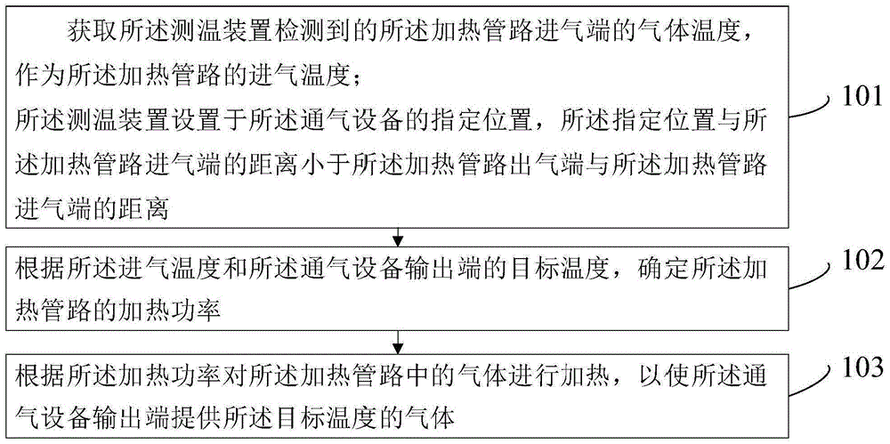
图1是本发明实施例提供的一种温度控制方法的步骤流程图,如图1所示,该温度控制方法应用于通气设备,所述通气设备包括测温装置、设备本体和加热管路,该方法可以包括:Fig. 1 is a flow chart of the steps of a temperature control method provided by an embodiment of the present invention. As shown in Fig. 1, the temperature control method is applied to ventilation equipment, and the ventilation equipment includes a temperature measuring device, a device body and a heating pipeline. The method can include:
步骤101、获取所述测温装置检测到的所述加热管路进气端的气体温度,作为所述加热管路的进气温度;所述测温装置设置于所述通气设备的指定位置,所述指定位置与所述加热管路进气端的距离小于所述加热管路出气端与所述加热管路进气端的距离。
本发明实施例的温度控制方法应用于通气设备,通气设备可以包括测温装置、设备本体和加热管路。其中,通气设备可以通过加热管路对气体进行加热。本发明实施例的设备本体可以提供待加热的气体,加热管路连接在设备本体上,用于加热来自设备本体输送的气体。其中,待加热的气体可以是氮气、氧气或者氦气,本发明实施例对此不作限制。The temperature control method of the embodiment of the present invention is applied to the ventilation equipment, and the ventilation equipment may include a temperature measuring device, a device body and a heating pipeline. Wherein, the ventilation equipment can heat the gas through the heating pipeline. The device body in the embodiment of the present invention can provide the gas to be heated, and the heating pipeline is connected to the device body for heating the gas delivered from the device body. Wherein, the gas to be heated may be nitrogen, oxygen or helium, which is not limited in this embodiment of the present invention.
本发明实施例中,测温装置可以设置于通气设备的指定位置,用于检测设备本体提供的气体的温度。其中,指定位置可以是加热管路进气端附近的预设位置,具体的,可以是设备本体侧的预设位置或者加热管路侧的预设位置,本发明实施例对此不做限制。指定位置与加热管路进气端的距离小于加热管路出气端与加热管路进气端的距离。其中,指定位置可以是加热管路上的预设位置,例如设置在加热管路的用于连接设备本体的接口处,接口处距离加热管路进气端的距离一般在厘米数量级,而加热管路的长度一般在米数量级,因此,接口处距离加热管路进气端的距离小于加热管路出气端与加热管路进气端的距离。或者,指定位置可以是设备本体上靠近加热管路的预设位置,例如,可以是距离加热管路接口2cm的设备本体内部的管路上,使得设备本体上的预设位置离加热管路进气端的距离小于加热管路出气端与加热管路进气端的距离。In the embodiment of the present invention, the temperature measuring device can be arranged at a designated position of the ventilating device, and is used to detect the temperature of the gas provided by the device body. Wherein, the specified position may be a preset position near the inlet end of the heating pipeline, specifically, it may be a preset position on the side of the device body or a preset position on the side of the heating pipeline, which is not limited in the embodiment of the present invention. The distance between the designated position and the inlet end of the heating pipeline is smaller than the distance between the outlet end of the heating pipeline and the inlet end of the heating pipeline. Wherein, the specified position can be a preset position on the heating pipeline, for example, it is set at the interface of the heating pipeline for connecting the device body, the distance between the interface and the inlet end of the heating pipeline is generally on the order of centimeters, and the distance of the heating pipeline is generally on the order of centimeters. The length is generally on the order of meters. Therefore, the distance between the interface and the inlet end of the heating pipeline is smaller than the distance between the outlet end of the heating pipeline and the inlet end of the heating pipeline. Alternatively, the specified position may be a preset position on the device body close to the heating pipeline, for example, it may be on the pipeline inside the device body 2 cm away from the heating pipeline interface, so that the preset position on the device body is far from the heating pipeline inlet The distance between the ends is less than the distance between the outlet end of the heating pipeline and the inlet end of the heating pipeline.
本发明实施例中,测温装置设置于加热管路的用于连接设备本体的接口处或者设备本体上靠近加热管路的预设位置,可以使得测温装置检测到的气体温度与加热管路始端实际的气体温度的温差不高于1摄氏度,例如,在本发明实施例的实际测试中,可以将温差控制在零点几度的量级。其中,测温装置可以是热敏电阻或气体温度传感器,此处仅是举例说明,本发明实施例对此不作限制。In the embodiment of the present invention, the temperature measuring device is arranged at the interface of the heating pipeline for connecting to the equipment body or at a preset position on the equipment body close to the heating pipeline, so that the temperature of the gas detected by the temperature measuring device can be compared with that of the heating pipeline. The actual gas temperature difference at the start end is not higher than 1 degree Celsius. For example, in the actual test of the embodiment of the present invention, the temperature difference can be controlled at the order of a few tenths of a degree. Wherein, the temperature measuring device may be a thermistor or a gas temperature sensor, which is only an example here, and is not limited in the embodiment of the present invention.
本发明实施例中,通气设备的控制装置可以获取测温装置的测量数据并对测量数据进行处理,其中,测量数据可以包括测温装置在一个时刻检测到的气体温度,或者在一段时间内检测到的一组气体温度。可以将一个时刻检测到的气体温度作为加热管路在该时刻的进气温度,也可以求一段时间内的一组气体温度的均值,作为加热管路在该时间段内工作时的平均进气温度,此处仅是举例说明,本发明实施例对此不作限制。其中,气体温度是设备本体产生的气体经过测温装置时被检测到的温度,进气温度用于表征气体进入加热管路时的温度,本发明实施例将测温装置检测到的气体温度作为加热管路的进气温度。In the embodiment of the present invention, the control device of the ventilation equipment can acquire the measurement data of the temperature measurement device and process the measurement data, wherein the measurement data can include the gas temperature detected by the temperature measurement device at a moment, or the gas temperature detected within a period of time to a set of gas temperatures. The gas temperature detected at a moment can be used as the intake air temperature of the heating pipeline at that moment, or the average value of a group of gas temperatures within a period of time can be calculated as the average intake air of the heating pipeline during the working period The temperature is just an example here, and the embodiment of the present invention does not limit it. Among them, the gas temperature is the temperature detected when the gas generated by the equipment body passes through the temperature measuring device, and the intake air temperature is used to represent the temperature when the gas enters the heating pipeline. In the embodiment of the present invention, the gas temperature detected by the temperature measuring device is used as The inlet temperature of the heating circuit.
步骤102、根据所述进气温度和所述通气设备输出端的目标温度,确定所述加热管路的加热功率。Step 102: Determine the heating power of the heating pipeline according to the intake air temperature and the target temperature at the output end of the ventilation device.
本发明实施例中,通气设备输出端可以是加热管路的末端,也可以是加热管路连接的接口装置的输出端,本发明实施例对此不做限制。目标温度可以通过响应用户对通气设置的温度设置操作,将用户设置的温度作为通气设备输出端的目标温度。本发明实施例的加热管路包括加热装置,其中加热装置可以是加热丝,加热丝可以嵌在管路壁上,也可以设置在管路内部,本发明实施例对此不作限制。In the embodiment of the present invention, the output end of the ventilation device may be the end of the heating pipeline, or the output end of the interface device connected to the heating pipeline, which is not limited in the embodiment of the present invention. The target temperature may be the temperature set by the user as the target temperature at the output end of the ventilation device by responding to the user's temperature setting operation on the ventilation setting. The heating pipeline in the embodiment of the present invention includes a heating device, wherein the heating device may be a heating wire, and the heating wire may be embedded in the pipeline wall or arranged inside the pipeline, which is not limited in the embodiment of the present invention.
本发明实施例中,可以根据进气温度和通气设备输出端的目标温度之间的差异,例如计算进气温度和目标温度的差值,可以根据进气温度和目标温度的差值获得加热管路中的气体所需上升的温度值。进一步地,可以根据气体所需上升的温度值以及气体本身的特性,确定加热管路中的加热装置所需的加热功率。其中,加热功率用于表征加热管路中的加热装置运行时的工作功率。In the embodiment of the present invention, according to the difference between the intake air temperature and the target temperature at the output end of the ventilation device, for example, the difference between the intake air temperature and the target temperature can be calculated, and the heating pipeline can be obtained according to the difference between the intake air temperature and the target temperature The temperature value that the gas in the gas needs to rise. Further, the heating power required by the heating device in the heating pipeline can be determined according to the required temperature rise of the gas and the characteristics of the gas itself. Among them, the heating power is used to characterize the working power of the heating device in the heating pipeline when it is running.
步骤103、根据所述加热功率对所述加热管路中的气体进行加热,以使所述通气设备输出端提供所述目标温度的气体。
本发明实施例中,通气设备的控制装置可以根据加热功率,控制加热管路中的加热装置产生相应的热能提供给加热管路中的气体,,加热管路中的气体吸收热能后温度升高,可以使得通气设备输出端的气体的温度达到目标温度。其中,加热管路可以通过电加热的方式,例如在加热管路中设置加热丝,当然也可以采用光波加热、磁场加热的方式对管路中的气体进行加热,此处仅是举例说明,本发明实施例对此不做限制。In the embodiment of the present invention, the control device of the ventilation equipment can control the heating device in the heating pipeline to generate corresponding heat energy for the gas in the heating pipeline according to the heating power, and the temperature of the gas in the heating pipeline rises after absorbing heat energy , the temperature of the gas at the output of the aerator can be brought to the target temperature. Among them, the heating pipeline can be heated by electricity, for example, a heating wire is arranged in the heating pipeline. Of course, the gas in the pipeline can also be heated by light wave heating or magnetic field heating. This is just an example. The embodiments of the invention do not limit this.
现有技术中,如图2所示,现有技术的加热管路通过在管路的出口设置测温点,例如通过热敏电阻或温度传感器检测气体的温度,进一步地通过比例积分微分控制(proportional-integral-derivative control,PID)控制模型控制加热功率,以对管路中的气体加热,实现对加热管路输出气体的温度控制。测温装置上连接的一定长度的线缆存在制造成本,这提高了现有技术的加热管路的制造成本。相比于现有技术,本发明实施例通过测温装置对加热管路进气端的气体温度进行检测,并通过通气设备的温度控制,实现对加热管路中气体的温度控制,从而使得通气设备输出端可以提供目标温度的气体。In the prior art, as shown in Figure 2, the heating pipeline of the prior art is provided with a temperature measuring point at the outlet of the pipeline, for example, the temperature of the gas is detected by a thermistor or a temperature sensor, and further controlled by proportional integral differential ( The proportional-integral-derivative control (PID) control model controls the heating power to heat the gas in the pipeline and realize the temperature control of the output gas of the heating pipeline. The cable of a certain length connected to the temperature measuring device has manufacturing cost, which increases the manufacturing cost of the heating pipeline in the prior art. Compared with the prior art, the embodiment of the present invention detects the gas temperature at the inlet end of the heating pipeline through the temperature measuring device, and realizes the temperature control of the gas in the heating pipeline through the temperature control of the ventilation equipment, so that the ventilation equipment The output can provide gas at the target temperature.
综上所述,本发明实施例提供的一种温度控制方法,通过获取测温装置检测到的所述加热管路进气端的气体温度,作为所述加热管路的进气温度;所述测温装置设置于所述通气设备的指定位置,所述指定位置与所述加热管路进气端的距离小于所述加热管路出气端与所述加热管路进气端的距离;根据所述进气温度和所述通气设备输出端的目标温度,确定所述加热管路的加热功率;根据所述加热功率对所述加热管路中的气体进行加热,以使所述通气设备输出端提供所述目标温度的气体。这样,通过将测温装置设置于靠近加热管路进气端的指定位置,并通过测温装置对加热管路进气端的气体温度进行检测,相比于现有技术中将测温装置设置于加热管路的出气端,可以减少测温装置连接的线缆的长度。因此,可以减少测温装置的线缆的制造成本,进而一定程度上可以降低加热管路的制造成本。To sum up, in the temperature control method provided by the embodiment of the present invention, the gas temperature at the inlet end of the heating pipeline detected by the temperature measuring device is obtained as the inlet temperature of the heating pipeline; The temperature device is set at a designated position of the ventilation equipment, and the distance between the designated position and the inlet end of the heating pipeline is smaller than the distance between the outlet end of the heating pipeline and the inlet end of the heating pipeline; temperature and the target temperature at the output end of the aeration device, determine the heating power of the heating pipeline; heat the gas in the heating pipeline according to the heating power, so that the output end of the aeration device provides the target temperature of the gas. In this way, by setting the temperature measuring device at a designated position close to the inlet end of the heating pipeline, and detecting the temperature of the gas at the inlet end of the heating pipeline through the temperature measuring device, compared with the prior art where the temperature measuring device is set at the heating The gas outlet end of the pipeline can reduce the length of the cable connected to the temperature measuring device. Therefore, the manufacturing cost of the cable of the temperature measuring device can be reduced, and thus the manufacturing cost of the heating pipeline can be reduced to a certain extent.
需要说明的是,本发明实施例的温度控制方法可以应用于普通工业领域的气体加热设备,例如涉及空压机或各类自带风源的设备上。可选的,该方法还可以应用于风道暖通行业内的气体加热设备,可以在涉及风道、空调箱补充热、仓库恒温系统等场景。It should be noted that the temperature control method of the embodiment of the present invention can be applied to gas heating equipment in the general industrial field, for example, involving air compressors or various equipment with its own air source. Optionally, this method can also be applied to gas heating equipment in the air duct HVAC industry, and can be used in scenarios involving air ducts, supplementary heat for air conditioning boxes, and warehouse constant temperature systems.
可选的,本发明实施例的温度控制方法可以应用于医疗设备领域的呼吸机等通气设备。示例性地,图3是本发明实施例的温度控制方法的应用场景示意图,如图3所示,通气设备为呼吸机,呼吸机包括设备本体、加热管路和面罩,其中,面罩是接口装置,由于面罩的结构特点,呼吸机输出端即加热管路的末端。测温装置安装在设备本体上,加热管路通过管路接头与设备本体连接。获取测温装置检测到的气体温度,作为加热管路的进气温度;根据进气温度T和呼吸机输出端,也即加热管路末端的目标温度,确定加热管路的加热功率;根据加热功率对加热管路中的气体进行加热,以使加热管路末端提供目标温度的气体。通气设备例如呼吸机,通常设置的目标温度在18~30摄氏度℃范围内,通气设备例如经鼻高流量湿化氧疗仪通常设置的目标温度在29~37摄氏度℃范围内。需要说明的是,实际应用场景中,呼吸机或经鼻高流量湿化氧疗仪的加热管路需要经常更换。因此,降低加热管路的制造成本,可以降低呼吸机或经鼻高流量湿化氧疗仪的使用成本,提高产品的市场竞争力。Optionally, the temperature control method in the embodiment of the present invention may be applied to ventilation equipment such as a ventilator in the field of medical equipment. Exemplarily, FIG. 3 is a schematic diagram of an application scenario of a temperature control method according to an embodiment of the present invention. As shown in FIG. 3 , the ventilator is a ventilator, and the ventilator includes a device body, a heating circuit, and a mask, wherein the mask is an interface device , due to the structural characteristics of the mask, the output end of the ventilator is the end of the heating circuit. The temperature measuring device is installed on the equipment body, and the heating pipeline is connected to the equipment body through the pipeline joint. Obtain the gas temperature detected by the temperature measuring device as the inlet temperature of the heating pipeline; determine the heating power of the heating pipeline according to the inlet temperature T and the output end of the ventilator, that is, the target temperature at the end of the heating pipeline; The power heats the gas in the heating line so that the end of the heating line provides gas at the target temperature. Ventilation equipment, such as a ventilator, usually sets the target temperature within the range of 18-30 degrees Celsius, and ventilation equipment such as a nasal high-flow humidified oxygen therapy device usually sets the target temperature within the range of 29-37 degrees Celsius. It should be noted that in actual application scenarios, the heating circuit of the ventilator or nasal high-flow humidified oxygen therapy device needs to be replaced frequently. Therefore, reducing the manufacturing cost of the heating circuit can reduce the use cost of the ventilator or the nasal high-flow humidified oxygen therapy device, and improve the market competitiveness of the product.
可选的,所述根据所述进气温度和所述通气设备输出端的目标温度,确定所述加热管路的加热功率之前,所述方法还包括:Optionally, before determining the heating power of the heating pipeline according to the intake air temperature and the target temperature at the output end of the ventilation device, the method further includes:
步骤104、获取气体通过所述加热管路所需的时长,作为气体加热时长。Step 104, obtaining the time required for the gas to pass through the heating pipeline as the gas heating time.
本发明实施例中,气体通过加热管路所需的时长可以根据通气设备输出的气体的流量、加热管路的长度和横截面积确定。其中,本发明实施例的通气设备可以在运行过程中以固定的流量输出气体,例如50升每分钟。根据气体的流量和加热管路的横截面积可以计算出加热管路中气体的流速,具体的,可以根据体积流量公式Q=VS,其中,Q代表气体的体积流量,V代表气体的平均流速单位是米每秒,S代表加热管路的横截面积单位是平方米。进一步地,根据气体流速和加热管路的长度,可以计算出气体通过加热管路所需的时长,可以将计算出的时长作为气体加热时长。In the embodiment of the present invention, the time required for the gas to pass through the heating pipeline can be determined according to the flow rate of the gas output by the ventilation device, the length and the cross-sectional area of the heating pipeline. Wherein, the ventilation device in the embodiment of the present invention can output gas at a fixed flow rate during operation, for example, 50 liters per minute. According to the gas flow rate and the cross-sectional area of the heating pipeline, the flow rate of the gas in the heating pipeline can be calculated. Specifically, the volume flow formula Q=VS can be used, where Q represents the volume flow rate of the gas, and V represents the average flow rate of the gas. The unit is meter per second, S represents the cross-sectional area of the heating pipeline and the unit is square meter. Further, according to the gas flow rate and the length of the heating pipeline, the time required for the gas to pass through the heating pipeline can be calculated, and the calculated time can be used as the gas heating time.
步骤1021、根据所述进气温度和所述气体加热时长,确定所述加热管路的温度损失值,得到第一损失值。Step 1021 : Determine the temperature loss value of the heating pipeline according to the intake air temperature and the gas heating time to obtain a first loss value.
本发明实施例中,在通过加热管路的过程中,气体被加热的同时也在对外做功,由于气体和加热管路各自的特性,例如加热管路的材质和厚度以及气体的比热容等,气体的热量会损失一部分,热量损失表现在气体温度上是温度值降低。气体的热量损失如以下公式所示:In the embodiment of the present invention, in the process of passing through the heating pipeline, the gas is heated and also works externally. Due to the respective characteristics of the gas and the heating pipeline, such as the material and thickness of the heating pipeline and the specific heat capacity of the gas, the gas Part of the heat will be lost, and the heat loss is manifested in the decrease of the temperature value of the gas temperature. The heat loss of the gas is given by the following formula:

ΔT=(T-Ta0ΔT=(T-Ta0
其中,QΔ为气体的热量损失,单位为焦耳J,ΔT为进气温度T和环境温度Ta的温差,单位为开尔文K,Δt为气体从加热管路始端到末端的时间单位为秒s,R1为加热管路的热阻,单位为开尔文每瓦特K/W。其中,加热管路的热阻可以根据如下公式计算:Among them, Q Δ is the heat loss of the gas, the unit is Joule J, ΔT is the temperature difference between the inlet temperature T and the ambient temperature Ta, the unit is Kelvin K, Δt is the time for the gas from the beginning to the end of the heating pipeline, and the unit is s, R 1 is the thermal resistance of the heating pipeline in Kelvin per watt K/W. Among them, the thermal resistance of the heating pipeline can be calculated according to the following formula:

其中,L为加热管路的厚度,单位为米m,λ为加热管路的导热系数,单位为瓦/米·开尔文W/(m.K),S为表面积单位为平方米。根据热量与比热容公式可以得到如下公式:Among them, L is the thickness of the heating pipeline, the unit is m, λ is the thermal conductivity of the heating pipeline, the unit is W/m Kelvin W/(m.K), and S is the surface area in square meters. According to the formula of heat and specific heat capacity, the following formula can be obtained:
QΔ=c×m(Ty″-Tx″)Q Δ =c×m(T y ″-T x ″)
其中,c为气体比热容,m为气体质量,Ty″为加热管路始端的气体温度也即进气温度,Tx″为管路末端气体温度。Wherein, c is the specific heat capacity of the gas, m is the mass of the gas, Ty ″ is the gas temperature at the beginning of the heating pipeline, that is, the inlet temperature, and T x ″ is the gas temperature at the end of the pipeline.
本发明实施例中,根据气体进入加热管路时的进气温度和气体加热时长,以及气体和管路的相关热损参数,可以计算出一定体积的气体通过加热管路后损失的热量。进一步地,根据计算获得的热量损失值,确定加热管路的温度损失值,作为第一损失值。其中,温度损失值用于表征气体损失的热量对应的气体温度降低的数值。In the embodiment of the present invention, the heat loss of a certain volume of gas passing through the heating pipeline can be calculated according to the intake temperature and the heating time of the gas when the gas enters the heating pipeline, and the related heat loss parameters of the gas and the pipeline. Further, according to the calculated heat loss value, the temperature loss value of the heating pipeline is determined as the first loss value. Wherein, the temperature loss value is used to represent the gas temperature reduction value corresponding to the heat lost by the gas.
步骤1022、根据所述进气温度、所述目标温度和所述第一损失值,计算所述加热管路中气体的温度上升值。Step 1022: Calculate the temperature rise value of the gas in the heating pipeline according to the intake air temperature, the target temperature and the first loss value.
本发明实施例中,根据气体进入加热管路的进气温度、用户对通气设置的目标温度和第一损失值也即一定体积的气体经过加热管路后的温度损失值,按照如下公式:温度上升值=进气温度–目标温度+第一损失值,计算一定体积的气体经过加热管路后所需的温度上升值。In the embodiment of the present invention, according to the intake temperature of the gas entering the heating pipeline, the target temperature set by the user for ventilation, and the first loss value, that is, the temperature loss value of a certain volume of gas after passing through the heating pipeline, the following formula is used: temperature Rise value = intake air temperature - target temperature + first loss value, calculate the temperature rise value required after a certain volume of gas passes through the heating pipeline.
步骤1023、根据所述温度上升值和所述气体加热时长,,确定所述加热管路的加热功率。Step 1023: Determine the heating power of the heating pipeline according to the temperature rise value and the gas heating time.
本发明实施例中,根据热力学第一定律:外界传给系统的热量,一部分用于增加系统内能,另外一部分用于系统对外做功。热力学系统在状态发生变化过程时,例如本实施例的加热管路对气体加热时,其物质系统的压强始终保持恒定。系统的压强始终保持不变的过程被称为等压过程,等压过程能量转化的特点是系统吸收的热量等于系统内能的增量和系统对外所做功之和,也即:系统从外界吸收的热量=内能增加+系统对外做功。本发明实施例中,系统可以认为是加热管路内的气体,外界可以认为是加热管路。管路内气体的内能增加可以认为是气体被加热带来气体温度上升。具体如以下公式所示:In the embodiment of the present invention, according to the first law of thermodynamics: part of the heat transmitted to the system from the outside is used to increase the internal energy of the system, and the other part is used for the external work of the system. When the state of the thermodynamic system changes, for example, when the heating pipeline in this embodiment heats the gas, the pressure of the material system remains constant. The process in which the pressure of the system remains constant is called an isobaric process. The characteristic of energy conversion in an isobaric process is that the heat absorbed by the system is equal to the sum of the increase in internal energy of the system and the work done by the system to the outside, that is, the system receives energy from the outside Absorbed heat = internal energy increase + external work done by the system. In the embodiment of the present invention, the system can be regarded as the gas in the heating pipeline, and the outside world can be regarded as the heating pipeline. The increase in the internal energy of the gas in the pipeline can be considered as the gas is heated and the temperature of the gas rises. The details are shown in the following formula:


其中,Qp为系统从外界吸收的热量,ΔE为气体内能增加值,W为气体对外做功值,M为气体质量,μ为气体摩尔质量,Cv是气体摩尔热容,摩尔气体常数R=8.31J/mol.K)单位焦耳每摩尔开尔文,Tx′为加热管路末端的气体温度,Ty′为加热管路始端的气体温度,(Tx′-y′)是气体经过加热管路后的温度上升值,i为气体自由度,待加热气体例如空气主要是氧气和氮气组成的双原子气体,i等于5。可选的,待加热气体还可以是氦气,氢气H2、氧气O2、氮气N2都是双原子分子,理想气体中双原子分子有五个自由度,既有3个平动自由度,又有2个转动自由度,总共有5个自由度,因此i等于5。Among them, Q p is the heat absorbed by the system from the outside world, ΔE is the value of gas internal energy increase, W is the external work value of gas, M is the mass of gas, μ is the molar mass of gas, C v is the molar heat capacity of gas, and the molar gas constant R =8.31J/mol.K) unit Joule per mole Kelvin, T x ′ is the gas temperature at the end of the heating pipeline, Ty ′ is the gas temperature at the beginning of the heating pipeline, (T x ′- y ′) is the gas after heating The temperature rise value behind the pipeline, i is the degree of freedom of the gas, the gas to be heated, such as air, is mainly a diatomic gas composed of oxygen and nitrogen, and i is equal to 5. Optionally, the gas to be heated can also be helium. Hydrogen H2, oxygen O2, and nitrogen N2 are all diatomic molecules. Diatomic molecules in an ideal gas have five degrees of freedom, including three translational degrees of freedom and two degrees of freedom. 2 rotational degrees of freedom, there are 5 degrees of freedom in total, so i equals 5.
本发明实施例中,加热管路的加热装置在一定时间内的产生的热量如以下公式所示:In the embodiment of the present invention, the heat generated by the heating device of the heating pipeline within a certain period of time is shown in the following formula:
Qp=P×Δt Qp = P× Δt
其中,P为加热管路的加热装置工作时的加热功率,Δt为气体加热时长。根据气体经过加热管路后所需的温度上升值和气体加热时长,可以计算出加热管路的加热装置在气体加热时长对应的时间段内所需产生的热量,进一步地,计算获得加热管路的加热装置工作时的加热功率P。Among them, P is the heating power of the heating device of the heating pipeline, and Δt is the gas heating time. According to the temperature rise value and gas heating time required for the gas passing through the heating pipeline, the heat required to be generated by the heating device of the heating pipeline in the time period corresponding to the gas heating time can be calculated, and further, the heating pipeline is obtained by calculation The heating power P when the heating device is working.
本发明实施例中,获取气体通过加热管路所需的时长,作为气体加热时长;根据进气温度和所述气体加热时长,确定加热管路的温度损失值,得到第一损失值;根据进气温度、目标温度和第一损失值,计算加热管路中气体的温度上升值;根据温度上升值和气体加热时长,确定加热管路的加热功率。这样,充分考虑气体在加热管路中的温度损失,通过计算温度损失值,可以使得根据温度损失值计算获得的气体所需的温度上升值更加准确。进一步地,根据温度上升值和气体加热时长确定的加热功率也更加准确,从而可以降低实际获得的温度上升值的误差,实现对气体的精确温度控制。In the embodiment of the present invention, the time required for the gas to pass through the heating pipeline is obtained as the gas heating time; according to the intake air temperature and the gas heating time, the temperature loss value of the heating pipeline is determined to obtain the first loss value; according to the Calculate the temperature rise value of the gas in the heating pipeline based on the gas temperature, target temperature and first loss value; determine the heating power of the heating pipeline according to the temperature rise value and the gas heating time. In this way, fully considering the temperature loss of the gas in the heating pipeline, by calculating the temperature loss value, the required temperature rise value of the gas calculated according to the temperature loss value can be more accurate. Furthermore, the heating power determined according to the temperature rise value and the gas heating time is also more accurate, so that the error of the actually obtained temperature rise value can be reduced, and precise temperature control of the gas can be realized.
可选的,所述根据所述进气温度和所述气体加热时长,确定所述加热管路的温度损失值之前,所述方法还包括:Optionally, before determining the temperature loss value of the heating pipeline according to the intake air temperature and the gas heating duration, the method further includes:
步骤105、获取所述通气设备所处的环境温度。Step 105, acquiring the ambient temperature where the ventilation device is located.
本发明实施例中,可以通过在通气设备中设置环境测温装置例如室温计等,获取通气设备所处的环境温度。其中,环境温度用于表征设备工作时所处的环境当前的气温。示例性的,通气设备通常具有规定的工作环境温度范围,例如呼吸机的工作环境温度在为5~35摄氏度℃温度范围内,经鼻高流量湿化氧疗仪的工作环境温度在18~28℃范围内。当然,也可以采用其他方式获取通气设备所处的环境温度,此处仅是举例说明,本发明实施例对此不做限制。In the embodiment of the present invention, the ambient temperature of the ventilation equipment can be obtained by setting an environmental temperature measuring device such as a room temperature meter in the ventilation equipment. Wherein, the ambient temperature is used to represent the current air temperature of the environment where the device is working. Exemplarily, ventilation equipment usually has a specified working environment temperature range, for example, the working environment temperature of the ventilator is in the temperature range of 5-35 degrees Celsius, and the working environment temperature of the nasal high-flow humidified oxygen therapy instrument is 18-28 degrees Celsius within range. Of course, other methods may also be used to acquire the ambient temperature where the ventilator is located, which is only used for illustration, and is not limited in this embodiment of the present invention.
可选的,步骤1021可以包括以下步骤:Optionally, step 1021 may include the following steps:
步骤10211、根据所述气体加热时长确定所述加热管路的温度损失参数。Step 10211. Determine the temperature loss parameter of the heating pipeline according to the gas heating time.
本发明实施例中,可以建立温降模型,温降模型用于表征温度损失值与气体的特性、加热管路的特性、进气温度、环境温度以及气体加热时长之间的关系。温度损失参数可以作为温降模型的模型系数,可以根据气体的特性、加热管路的特性和气体加热时长确定,且与气体加热时长正相关。In the embodiment of the present invention, a temperature drop model can be established, and the temperature drop model is used to characterize the relationship between the temperature loss value and the characteristics of the gas, the characteristics of the heating pipeline, the intake air temperature, the ambient temperature, and the heating time of the gas. The temperature loss parameter can be used as the model coefficient of the temperature drop model, which can be determined according to the characteristics of the gas, the characteristics of the heating pipeline and the gas heating time, and is positively correlated with the gas heating time.
步骤10212、根据所述进气温度、所述环境温度和所述温度损失参数,计算所述温度损失值,得到第一损失值。Step 10212: Calculate the temperature loss value according to the intake air temperature, the ambient temperature and the temperature loss parameter to obtain a first loss value.
本发明实施例中,基于温降模型,可以根据气体进入加热管路时的进气温度、通气设备所处的环境温度和温降模型的温度损失参数,按照如下公式:第一损失值=温度损失参数×(进气温度-环境温度),计算气体经过加热管路热量损失对应的温度损失值,得到第一损失值。本发明实施例中,气体经过加热管路被加热装置加热的过程,也是加热管路依靠自身材质、厚度对管路中的气体进行保温的过程,其中,管路热阻越大,气体的温降幅度越小,管路末端的气体温度越接近管路始端的气体温度。In the embodiment of the present invention, based on the temperature drop model, the intake temperature when the gas enters the heating pipeline, the ambient temperature where the ventilation equipment is located, and the temperature loss parameters of the temperature drop model can be used according to the following formula: first loss value=temperature Loss parameter × (intake temperature - ambient temperature), calculate the temperature loss value corresponding to the heat loss of the gas passing through the heating pipeline, and obtain the first loss value. In the embodiment of the present invention, the process of the gas passing through the heating pipeline and being heated by the heating device is also the process of the heating pipeline relying on its own material and thickness to keep the gas in the pipeline warm. The smaller the drop, the closer the gas temperature at the end of the pipeline is to the gas temperature at the beginning of the pipeline.
本发明实施例中,通过获取通气设备所处的环境温度;;根据气体加热时长确定加热管路的温度损失参数;根据进气温度、环境温度和温度损失参数,计算温度损失值,得到第一损失值。这样,根据气体加热时长确定加热管路的温度损失参数,可以简化温度损失值的计算步骤,可以根据进气温度、环境温度和温度损失参数,方便地计算温度损失值,得到第一损失值。In the embodiment of the present invention, by obtaining the ambient temperature of the ventilation equipment; determining the temperature loss parameter of the heating pipeline according to the gas heating time; calculating the temperature loss value according to the intake air temperature, ambient temperature and temperature loss parameters, and obtaining the first loss value. In this way, determining the temperature loss parameter of the heating pipeline according to the gas heating time can simplify the calculation steps of the temperature loss value, and can conveniently calculate the temperature loss value according to the intake air temperature, ambient temperature and temperature loss parameters to obtain the first loss value.
可选的,步骤1023可以包括以下步骤:Optionally, step 1023 may include the following steps:
步骤10231、根据所述气体加热时长确定所述加热管路的温度上升参数。Step 10231. Determine the temperature rise parameter of the heating pipeline according to the gas heating duration.
本发明实施例中,可以建立升温模型,升温模型用于表征温度上升值与气体的特性、气体加热时长和加热管路的加热功率之间的关系。加热管路的加热装置对气体加热的过程是热传导的过程,热传导是指当不同物体之间或同一物体内部存在温度差时,就会通过物体内部分子、原子和电子的微观振动、位移和相互碰撞而发生能量传递现象。热传导的效果与气体本身的特性有关,气体被加热,接收热量从而气体内能增加,表现为气体的温度上升。温度上升参数可以作为升温模型的模型系数,可以根据气体的特性和气体加热时长确定,且与气体加热时长正相关。In the embodiment of the present invention, a temperature rise model can be established, and the temperature rise model is used to characterize the relationship between the temperature rise value and the characteristics of the gas, the gas heating time, and the heating power of the heating pipeline. The process of heating the gas by the heating device of the heating pipeline is the process of heat conduction. Heat conduction means that when there is a temperature difference between different objects or inside the same object, it will pass through the microscopic vibration, displacement and mutual collision of molecules, atoms and electrons inside the object. energy transfer occurs. The effect of heat conduction is related to the characteristics of the gas itself. The gas is heated and receives heat so that the internal energy of the gas increases, which is expressed as the temperature of the gas rises. The temperature rise parameter can be used as the model coefficient of the temperature rise model, which can be determined according to the characteristics of the gas and the gas heating time, and is positively correlated with the gas heating time.
步骤10232、根据所述温度上升值和所述温度上升参数,计算所述加热管路的加热功率。Step 10232: Calculate the heating power of the heating pipeline according to the temperature rise value and the temperature rise parameter.
本发明实施例中,基于升温模型,可以根据气体通过加热管路后所需的温度上升值,升温模型的温度上升参数,按照如下公式:加热功率=温度上升值/温度上升参数,计算气体的温度变化满足温度上升值,,需要加热管路的加热装置提供的热量对应的加热装置的加热工作功率。In the embodiment of the present invention, based on the temperature rise model, the temperature rise parameter of the temperature rise model can be calculated according to the following formula: heating power=temperature rise value/temperature rise parameter according to the required temperature rise value after the gas passes through the heating pipeline. The temperature change meets the temperature rise value, and the heating power of the heating device corresponding to the heat provided by the heating device of the heating pipeline is required.
本发明实施例中,通过根据气体加热时长确定加热管路的温度上升参数;根据温度上升值和温度上升参数,计算所述加热管路的加热功率。这样,根据气体加热时长确定加热管路的温度上升参数,可以简化加热功率的计算步骤,可以根据温度上升值和温度上升参数,方便地计算加热管路的加热功率。In the embodiment of the present invention, the temperature rise parameter of the heating pipeline is determined according to the gas heating time; and the heating power of the heating pipeline is calculated according to the temperature rise value and the temperature rise parameter. In this way, determining the temperature rise parameter of the heating pipeline according to the gas heating time can simplify the calculation steps of the heating power, and can conveniently calculate the heating power of the heating pipeline according to the temperature rise value and the temperature rise parameter.
可选的,步骤10211可以包括以下步骤:Optionally, step 10211 may include the following steps:
步骤10211a、获取所述加热管路的热量损失参数和管路保温参数,以及所述加热管路中气体的气体保温参数。Step 10211a, acquire the heat loss parameter and pipeline insulation parameter of the heating pipeline, and the gas insulation parameter of the gas in the heating pipeline.
本发明实施例中,加热管路的热量损失参数用于表征与加热管路的热量损失有关的加热管路的特性,例如可以是加热管路的导热系数和表面积。加热管路的管路保温参数用于表征与加热管路的保温效果有关的加热管路的特性,例如可以是管路的厚度。加热管路中气体的气体保温参数用于表征与气体的保温效果有关的气体的特性,例如气体的比热容、气体的质量,此处仅是举例说明,本发明实施例对此不做限制。In the embodiment of the present invention, the heat loss parameter of the heating pipeline is used to characterize the characteristics of the heating pipeline related to the heat loss of the heating pipeline, such as the thermal conductivity and surface area of the heating pipeline. The pipeline insulation parameter of the heating pipeline is used to characterize the characteristics of the heating pipeline related to the insulation effect of the heating pipeline, for example, it may be the thickness of the pipeline. The gas heat preservation parameters of the gas in the heating pipeline are used to characterize the properties of the gas related to the heat preservation effect of the gas, such as the specific heat capacity of the gas and the quality of the gas. This is only an example and is not limited by the embodiment of the present invention.
步骤10211b、根据所述气体加热时长、所述加热管路的热量损失参数和管路保温参数,以及所述加热管路中气体的气体保温参数,计算所述加热管路的温度损失参数;其中,所述温度损失参数与所述气体加热时长和所述热量损失参数正相关,以及所述温度损失参数与所述管路保温参数和所述气体保温参数负相关。Step 10211b: Calculate the temperature loss parameter of the heating pipeline according to the heating time of the gas, the heat loss parameter of the heating pipeline, the pipeline insulation parameter, and the gas insulation parameter of the gas in the heating pipeline; wherein , the temperature loss parameter is positively correlated with the gas heating time and the heat loss parameter, and the temperature loss parameter is negatively correlated with the pipeline insulation parameter and the gas insulation parameter.
本发明实施例中,温降模型的公式如以下所示:In the embodiment of the present invention, the formula of the temperature drop model is as follows:

其中,Ty″为加热管路始端的气体温度也即进气温度,Tx″为加热管路末端气体温度,Ty″-Tx″表示气体的温度损失值,λ为加热管路的导热系数,S为表面积,Δt为气体加热时长,T为进气温度,Ta为环境温度,c为气体比热容,m为气体质量,L为加热管路的厚度。则可以根据气体加热时长、加热管路的热量损失参数和管路保温参数,以及加热管路中气体的气体保温参数,按照如下公式:
计算加热管路的温度损失参数T损。其中,温度损失参数T损与加热管路导热系数λ、管路表面积S和气体加热时长正相关Δt,与气体的比热容c、气体的质量m和管路的厚度L负相关。Calculate the temperature loss parameter T loss of the heating pipeline. Among them, the temperature loss parameter Tloss is positively correlated with the thermal conductivity λ of the heating pipeline, the surface area of the pipeline S and the gas heating time Δt , and negatively correlated with the specific heat capacity c of the gas, the mass m of the gas and the thickness L of the pipeline.
示例性的,呼吸机的工作温度范围为5~35℃,气体流量范围是20~200升每分钟,可以通过试验获取5、10、15、20、25、30、35摄氏度的温度损失参数,将温度损失参数做成矩阵列表,如图4所示,其中,H-N分别对应5、10、15、20、25、30、35摄氏度,1-10分别对应流量20、40、60、80、100、120、140、160、180、200升每分钟流量。其中,H1表示呼吸机在5℃环境温度,和20升每分钟流量的情况下对应的温度损失参数,此处仅是举例说明,本发明实施例对此不做限制。在呼吸机实际运行的过程中,可以快速地通过查询温度损失参数矩阵的方式,方便地获得相应情况下的温度损失参数。Exemplarily, the operating temperature range of the ventilator is 5-35°C, the gas flow range is 20-200 liters per minute, and the temperature loss parameters of 5, 10, 15, 20, 25, 30, and 35°C can be obtained through experiments, Make the temperature loss parameters into a matrix list, as shown in Figure 4, where H-N corresponds to 5, 10, 15, 20, 25, 30, and 35 degrees Celsius, and 1-10 corresponds to flow rates of 20, 40, 60, 80, and 100 , 120, 140, 160, 180, 200 liters per minute flow. Wherein, H1 represents the corresponding temperature loss parameter of the ventilator at an ambient temperature of 5° C. and a flow rate of 20 liters per minute. This is only an example for illustration, and is not limited in this embodiment of the present invention. During the actual operation of the ventilator, the temperature loss parameters in corresponding situations can be obtained conveniently by quickly querying the temperature loss parameter matrix.
本发明实施例中,通过获取加热管路的热量损失参数和管路保温参数,以及加热管路中气体的气体保温参数;根据气体加热时长、加热管路的热量损失参数和管路保温参数,以及加热管路中气体的气体保温参数,计算加热管路的温度损失参数;其中,温度损失参数与气体加热时长、进气温度、环境温度和热量损失参数正相关,以及温度损失参数与管路保温参数和气体保温参数负相关。这样,预先计算获得温度损失参数,可以方便根据温度损失参数进行相关计算。In the embodiment of the present invention, by obtaining the heat loss parameter and pipeline insulation parameter of the heating pipeline, and the gas insulation parameter of the gas in the heating pipeline; according to the gas heating time, the heat loss parameter of the heating pipeline and the pipeline insulation parameter, As well as the gas insulation parameters of the gas in the heating pipeline, the temperature loss parameters of the heating pipeline are calculated; among them, the temperature loss parameter is positively related to the gas heating time, inlet temperature, ambient temperature and heat loss parameters, and the temperature loss parameter is related to the pipeline The insulation parameters are negatively correlated with the gas insulation parameters. In this way, the temperature loss parameters are obtained through pre-calculation, which can facilitate related calculations based on the temperature loss parameters.
可选的,步骤10231可以包括以下步骤:Optionally, step 10231 may include the following steps:
步骤10231a、获取所述加热管路中气体的内能增加参数和对外做功参数。Step 10231a, acquire the internal energy increase parameters and external work parameters of the gas in the heating pipeline.
本发明实施例中,加热管路中气体的内能增加参数用于表征与气体的内能增加有关的气体的特性,例如气体摩尔质量。加热管路中气体的对外做功参数用于表征与气体对外做功有关的气体的特性,例如气体摩尔热容和气体质量M,此处仅是举例说明,本发明实施例对此不做限制。In the embodiment of the present invention, the internal energy increase parameter of the gas in the heating pipeline is used to characterize the characteristics of the gas related to the internal energy increase of the gas, such as the molar mass of the gas. The external work parameters of the gas in the heating pipeline are used to characterize the characteristics of the gas related to the external work of the gas, such as the gas molar heat capacity and the gas mass M, which are just examples here and are not limited in the embodiment of the present invention.
步骤10231b、根据所述气体加热时长以及所述加热管路中气体的内能增加参数和对外做功参数,计算所述加热管路的温度上升参数;其中,所述温度上升参数与所述气体加热时长和所述内能增加参数正相关,所述温度上升参数与所述对外做功参数负相关。Step 10231b: Calculate the temperature rise parameter of the heating pipeline according to the heating time of the gas, the internal energy increase parameter and the external work parameter of the gas in the heating pipeline; wherein, the temperature rise parameter and the gas heating The duration is positively correlated with the internal energy increase parameter, and the temperature rise parameter is negatively correlated with the external work parameter.
本发明实施例中,升温模型的公式如以下所示:In the embodiment of the present invention, the formula of the heating model is as follows:

其中,Tx′为管路末端气体温度,Ty′为管路始端气体温度,(Tx′-y′)为气体的温度上升值,μ为气体摩尔质量,Δt为气体加热时长,Cv为气体摩尔热容,M为气体质量,P为加热功率。则可以根据气体加热时长以及加热管路中气体的内能增加参数和对外做功参数,按照如下公式:Among them, T x ′ is the gas temperature at the end of the pipeline, Ty ′ is the gas temperature at the beginning of the pipeline, (T x ′- y ′) is the temperature rise of the gas, μ is the molar mass of the gas, Δ t is the heating time of the gas, C v is the gas molar heat capacity, M is the gas mass, and P is the heating power. Then you can increase the parameters and external work parameters according to the gas heating time and the internal energy of the gas in the heating pipeline, according to the following formula:

计算所述加热管路的温度上升参数T升。其中,温度上升参数T升与气体加热时长Δt和气体摩尔质量μ正相关,温度上升参数T升与气体摩尔热容Cv、气体质量M负相关。Calculate the temperature rise parameter T liter of the heating pipeline. Among them, the temperature rise parameter T liter is positively correlated with the gas heating time Δ t and the gas molar mass μ, and the temperature rise parameter T liter is negatively correlated with the gas molar heat capacity C v and the gas mass M.
示例性的,呼吸机的工作温度范围为5~35℃,气体流量范围是20~200升每分钟,可以通过试验获取5、10、15、20、25、30、35摄氏度的温度上升参数,将温度上升参数做成矩阵列表,如图5所示,其中,A-G分别对应5、10、15、20、25、30、35摄氏度,1-10分别对应流量20、40、60、80、100、120、140、160、180、200升每分钟流量。其中,A1表示呼吸机在5℃环境温度,和20升每分钟流量的情况下对应的温度上升参数,此处仅是举例说明,本发明实施例对此不做限制。需要说明的是,在呼吸机实际运行的过程中,流量一般是计算平均流量,因此温度上升参数为平均温度上升参数,可以快速地通过查询温度上升参数矩阵的方式,方便地获得相应情况下的温度上升参数。Exemplarily, the operating temperature range of the ventilator is 5-35°C, the gas flow range is 20-200 liters per minute, and the temperature rise parameters of 5, 10, 15, 20, 25, 30, and 35°C can be obtained through experiments, Make the temperature rise parameters into a matrix list, as shown in Figure 5, where A-G corresponds to 5, 10, 15, 20, 25, 30, and 35 degrees Celsius, and 1-10 corresponds to flow rates of 20, 40, 60, 80, and 100 , 120, 140, 160, 180, 200 liters per minute flow. Wherein, A1 represents the corresponding temperature rise parameter of the ventilator at an ambient temperature of 5° C. and a flow rate of 20 liters per minute. This is only an example and is not limited in this embodiment of the present invention. It should be noted that during the actual operation of the ventilator, the flow rate is generally calculated as the average flow rate, so the temperature rise parameter is the average temperature rise parameter, and the temperature rise parameter matrix can be quickly obtained by querying the temperature rise parameter matrix. temperature rise parameter.
本发明实施例中,通过获取加热管路中气体的内能增加参数和对外做功参数;根据气体加热时长以及加热管路中气体的内能增加参数和对外做功参数,计算加热管路的温度上升参数;其中,温度上升参数与气体加热时长和内能增加参数正相关,温度上升参数与所述对外做功参数负相关。这样,预先计算获得温度上升参数,可以方便根据温度上升参数进行相关计算。In the embodiment of the present invention, by obtaining the internal energy increase parameters and external work parameters of the gas in the heating pipeline; according to the gas heating time and the internal energy increase parameters and external work parameters of the gas in the heating pipeline, the temperature rise of the heating pipeline is calculated Parameters; wherein, the temperature rise parameter is positively correlated with the gas heating duration and the internal energy increase parameter, and the temperature rise parameter is negatively correlated with the external work parameter. In this way, the temperature rise parameter is obtained through pre-calculation, which can facilitate related calculations based on the temperature rise parameter.
可选的,如图6所示,可以为本发明实施例的温度控制方法建立温度控制模型,在通气设备的输出端就是加热管路的末端的情况下,例如呼吸机中加热管路连接面罩的情况下,温度控制模型可以包括加热管路升温模型和加热管路温降模型。可以根据温度控制模型实现对加热管路中气体的精确温度控制。Optionally, as shown in Figure 6, a temperature control model can be established for the temperature control method of the embodiment of the present invention. In the case where the output end of the ventilator is the end of the heating circuit, for example, the heating circuit in the ventilator is connected to the mask In the case of , the temperature control model can include a heating pipeline temperature rise model and a heating pipeline temperature drop model. The precise temperature control of the gas in the heating pipeline can be realized according to the temperature control model.
可选的,在所述通气设备还包括接口装置的情况下,所述方法还包括:Optionally, in the case where the ventilation device further includes an interface device, the method further includes:
步骤201、根据所述气体加热时长确定所述接口装置的温度损失参数。Step 201. Determine the temperature loss parameter of the interface device according to the gas heating duration.
本发明实施例中,可以建立接口装置温降模型,接口装置温降模型用于表征接口装置温度损失值与气体的特性、接口装置的特性、进气温度、环境温度以及气体加热时长之间的关系。接口装置温度损失参数可以作为接口装置温降模型的模型系数,可以根据气体的特性、接口装置的特性和气体加热时长确定,且与气体加热时长正相关。In the embodiment of the present invention, the temperature drop model of the interface device can be established, and the temperature drop model of the interface device is used to characterize the relationship between the temperature loss value of the interface device and the characteristics of the gas, the characteristics of the interface device, the intake air temperature, the ambient temperature, and the heating time of the gas. relation. The temperature loss parameter of the interface device can be used as the model coefficient of the temperature drop model of the interface device, which can be determined according to the characteristics of the gas, the characteristics of the interface device and the gas heating time, and is positively correlated with the gas heating time.
示例性的,经鼻高流量湿化氧疗仪的工作温度范围为18~28℃,气体流量范围是20~200升每分钟,可以通过试验获取18、20、22、24、26、28摄氏度的温度损失参数,将温度损失参数做成矩阵列表,如图7所示,其中,h-m分别对应18、20、22、24、26、28摄氏度,1-10分别对应流量20、40、60、80、100、120、140、160、180、200升每分钟流量。其中,h1表示经鼻高流量湿化氧疗仪在5℃环境温度,和20升每分钟流量的情况下对应的鼻氧管温度损失参数,此处仅是举例说明,本发明实施例对此不做限制。在经鼻高流量湿化氧疗仪实际运行的过程中,可以快速地通过查询鼻氧管温度损失参数矩阵的方式,方便地获得相应情况下的鼻氧管温度损失参数。Exemplarily, the operating temperature range of the nasal high-flow humidified oxygen therapy instrument is 18-28°C, the gas flow range is 20-200 liters per minute, and the temperature range of 18, 20, 22, 24, 26, and 28°C can be obtained through experiments. Temperature loss parameters, the temperature loss parameters are made into a matrix list, as shown in Figure 7, where h-m corresponds to 18, 20, 22, 24, 26, and 28 degrees Celsius, and 1-10 corresponds to flow rates of 20, 40, 60, and 80 , 100, 120, 140, 160, 180, 200 liters per minute flow. Among them, h1 represents the temperature loss parameter of the nasal oxygen tube corresponding to the ambient temperature of 5°C and the flow rate of 20 liters per minute of the nasal high-flow humidified oxygen therapy instrument. Do limit. During the actual operation of the nasal high-flow humidified oxygen therapy device, the temperature loss parameters of the nasal oxygen tube can be quickly and conveniently obtained by querying the temperature loss parameter matrix of the nasal oxygen tube.
步骤202、根据所述进气温度、所述环境温度和所述接口装置的温度损失参数,计算所述接口装置的温度损失值,得到第二损失值;Step 202. Calculate the temperature loss value of the interface device according to the intake air temperature, the ambient temperature, and the temperature loss parameter of the interface device to obtain a second loss value;
本发明实施例中,基于接口装置温降模型,可以根据气体进入接口装置时的进气温度、通气设备所处的环境温度和接口装置温降模型的温度损失参数,按照如下公式:第二损失值=接口装置温度损失参数×(装置进气温度-环境温度),计算气体经过接口装置热量损失对应的温度损失值,得到第二损失值。本发明实施例中,气体经过接口装置的过程,也是接口装置依靠自身材质、厚度对接口装置中的气体进行保温的过程,其中,接口装置热阻越大,气体的温降幅度越小,接口装置末端的气体温度越接近接口装置始端的气体温度。In the embodiment of the present invention, based on the temperature drop model of the interface device, the following formula can be used according to the intake temperature when the gas enters the interface device, the ambient temperature of the ventilation equipment, and the temperature loss parameters of the temperature drop model of the interface device: the second loss Value = interface device temperature loss parameter × (device intake temperature - ambient temperature), calculate the temperature loss value corresponding to the heat loss of the gas passing through the interface device, and obtain the second loss value. In the embodiment of the present invention, the process of gas passing through the interface device is also the process of the interface device relying on its own material and thickness to keep the gas in the interface device warm. The greater the thermal resistance of the interface device, the smaller the temperature drop of the gas, and the interface The gas temperature at the end of the device is closer to the gas temperature at the beginning of the interface device.
示例性地,图8是本发明实施例的另一温度控制方法的应用场景示意图,如图8所示,通气设备为经鼻高流量湿化氧疗仪,经鼻高流量湿化氧疗仪包括设备本体、加热管路和鼻氧管,其中,鼻氧管是接口装置,由于鼻氧管的结构特点,经鼻高流量湿化氧疗仪输出端是鼻氧管的末端。测温装置安装在设备本体上,加热管路通过管路接头与设备本体连接。获取测温装置检测到的气体温度,作为加热管路的进气温度;根据进气温度T和经鼻高流量湿化氧疗仪输出端,也即鼻氧管末端的目标温度,确定加热管路的加热功率;根据加热功率对加热管路中的气体进行加热,以使鼻氧管末端提供目标温度的气体。Exemplarily, FIG. 8 is a schematic diagram of an application scenario of another temperature control method according to an embodiment of the present invention. As shown in FIG. 8 , the ventilation device is a nasal high-flow humidified oxygen therapy device, and the nasal high-flow humidified oxygen therapy device includes equipment The main body, the heating pipeline and the nasal oxygen tube. The nasal oxygen tube is the interface device. Due to the structural characteristics of the nasal oxygen tube, the output end of the nasal high-flow humidified oxygen therapy instrument is the end of the nasal oxygen tube. The temperature measuring device is installed on the equipment body, and the heating pipeline is connected to the equipment body through the pipeline joint. Obtain the gas temperature detected by the temperature measuring device as the inlet temperature of the heating pipeline; determine the heating pipeline according to the inlet temperature T and the output end of the nasal high-flow humidified oxygen therapy device, that is, the target temperature at the end of the nasal oxygen tube The heating power; according to the heating power, the gas in the heating pipeline is heated so that the end of the nasal oxygen tube can provide the gas at the target temperature.
可选的,步骤1022可以包括以下步骤:Optionally, step 1022 may include the following steps:
步骤10221、根据所述进气温度、所述目标温度、所述第一温度损失值以及所述第二损失值,计算所述加热管路中气体的温度上升值。Step 10221: Calculate the temperature rise value of the gas in the heating pipeline according to the intake air temperature, the target temperature, the first temperature loss value and the second loss value.
本发明实施例中,根据气体进入加热管路的进气温度、用户对通气设置的目标温度和第一损失值也即一定体积的气体经过加热管路后的温度损失值,以及第二损失值也即一定体积的气体经过接口装置后的温度损失值,按照如下公式:温度上升值=进气温度–目标温度+第一损失值+第二损失值,计算一定体积的气体经过加热管路后所需的温度上升值。In the embodiment of the present invention, according to the intake temperature of the gas entering the heating pipeline, the target temperature set by the user for ventilation, the first loss value, that is, the temperature loss value of a certain volume of gas passing through the heating pipeline, and the second loss value That is, the temperature loss value of a certain volume of gas after passing through the interface device, according to the following formula: temperature rise value = intake air temperature - target temperature + first loss value + second loss value, calculate a certain volume of gas after passing through the heating pipeline The desired temperature rise value.
可选的,如图9所示,可以为本发明实施例的温度控制方法建立温度控制模型,在通气设备的输出端就是接口装置的末端的情况下,例如经鼻高流量湿化氧疗仪中加热管路连接鼻氧管的情况下,温度控制模型可以包括加热管路升温模型、加热管路温降模型和接口装置温降模型。需要说明的是接口装置例如鼻氧管属于无源管路,不带电,因此只有相应的温降模型。接口装置温降模型与加热管路温降模型的不同点是接口装置例如鼻氧管,鼻氧管的材料、形状、厚度与加热管路都有区别,因此,相应的鼻氧管温度损失参数也有所差异。Optionally, as shown in FIG. 9, a temperature control model can be established for the temperature control method of the embodiment of the present invention. In the case where the output end of the ventilation device is the end of the interface device, for example, in a nasal high-flow humidified oxygen therapy instrument When the heating pipeline is connected to the nasal oxygen tube, the temperature control model may include a heating pipeline temperature rise model, a heating pipeline temperature drop model, and an interface device temperature drop model. It should be noted that interface devices such as nasal oxygen tubes are passive pipelines and are not charged, so there is only a corresponding temperature drop model. The difference between the temperature drop model of the interface device and the temperature drop model of the heating pipeline is that the material, shape, thickness of the interface device such as the nasal oxygen tube and the heating pipeline are different. Therefore, the corresponding temperature loss parameters of the nasal oxygen tube There are also differences.
本发明实施例中,通过根据气体加热时长确定接口装置的温度损失参数;根据进气温度、环境温度和接口装置的温度损失参数,计算接口装置的温度损失值,得到第二损失值;根据进气温度、目标温度、第一温度损失值以及第二损失值,计算加热管路中气体的温度上升值。这样,可以将接口装置的温度损失考虑在内,使得计算加热管路中气体的温度上升值更加准确,从而实现对加热管路中气体的精确温度控制,进一步地,可以减小通气设备的输出端即接口装置末端的气体目标温度的误差。In the embodiment of the present invention, the temperature loss parameter of the interface device is determined according to the gas heating time; the temperature loss value of the interface device is calculated according to the intake air temperature, the ambient temperature and the temperature loss parameter of the interface device, and the second loss value is obtained; Calculate the temperature rise value of the gas in the heating pipeline based on the gas temperature, the target temperature, the first temperature loss value and the second loss value. In this way, the temperature loss of the interface device can be taken into account, making the calculation of the temperature rise of the gas in the heating pipeline more accurate, thereby realizing precise temperature control of the gas in the heating pipeline, and further reducing the output of the ventilation equipment The error in the target temperature of the gas at the end, that is, the end of the interface device.
图10为本发明实施例所述的一种温度控制装置30的框图。如图10所示,所述温度控制装置30应用于通气设备,所述通气设备包括测温装置、设备本体和加热管路,该装置30,可以包括:Fig. 10 is a block diagram of a temperature control device 30 according to an embodiment of the present invention. As shown in Figure 10, the temperature control device 30 is applied to ventilation equipment, and the ventilation equipment includes a temperature measuring device, a device body and a heating pipeline. The device 30 may include:
第一获取模块301,用于获取所述测温装置检测到的所述加热管路进气端的气体温度,作为所述加热管路的进气温度;所述测温装置设置于所述通气设备的指定位置,所述指定位置与所述加热管路进气端的距离小于所述加热管路出气端与所述加热管路进气端的距离;The first acquisition module 301 is used to acquire the gas temperature at the inlet end of the heating pipeline detected by the temperature measuring device as the intake air temperature of the heating pipeline; the temperature measuring device is arranged on the ventilation equipment The designated position, the distance between the designated position and the inlet end of the heating pipeline is smaller than the distance between the outlet end of the heating pipeline and the inlet end of the heating pipeline;
第一确定模块302,用于根据所述进气温度和所述通气设备输出端的目标温度,确定所述加热管路的加热功率;The first determination module 302 is configured to determine the heating power of the heating pipeline according to the intake air temperature and the target temperature at the output end of the ventilation device;
控制模块303,用于根据所述加热功率对所述加热管路中的气体进行加热,以使所述通气设备输出端提供所述目标温度的气体。The control module 303 is configured to heat the gas in the heating pipeline according to the heating power, so that the output end of the ventilation device provides gas at the target temperature.
可选的,所述装置30还包括:Optionally, the device 30 also includes:
第二获取模块,用于所述第一确定模块302根据所述进气温度和所述通气设备输出端的目标温度,确定所述加热管路的加热功率之前,获取气体通过所述加热管路所需的时长,作为气体加热时长;The second acquisition module is used for the first determination module 302 to obtain the temperature of the gas passing through the heating pipeline before determining the heating power of the heating pipeline according to the intake air temperature and the target temperature of the output end of the ventilation device. The required time is used as the gas heating time;
所述第一确定模块302具体用于:根据所述进气温度和所述气体加热时长,确定所述加热管路的温度损失值,得到第一损失值;根据所述进气温度、所述目标温度和所述第一损失值,计算所述加热管路中气体的温度上升值;根据所述温度上升值和所述气体加热时长,确定所述加热管路的加热功率。The first determination module 302 is specifically configured to: determine the temperature loss value of the heating pipeline according to the intake air temperature and the gas heating time to obtain a first loss value; according to the intake air temperature, the Calculate the temperature rise value of the gas in the heating pipeline according to the target temperature and the first loss value; determine the heating power of the heating pipeline according to the temperature rise value and the heating time of the gas.
可选的,所述根据所述进气温度和所述气体加热时长,确定所述加热管路的温度损失值之前,所述装置还包括:Optionally, before determining the temperature loss value of the heating pipeline according to the intake air temperature and the gas heating time, the device further includes:
第三获取模块,用于所述第一确定模块302根据所述进气温度和所述气体加热时长,确定所述加热管路的温度损失值之前,获取所述通气设备所处的环境温度;The third acquisition module is used for the first determination module 302 to acquire the ambient temperature of the ventilation device before determining the temperature loss value of the heating pipeline according to the intake air temperature and the gas heating time;
所述第一确定模块302具体还用于:根据所述气体加热时长确定所述加热管路的温度损失参数;根据所述进气温度、所述环境温度和所述温度损失参数,计算所述温度损失值,得到第一损失值。The first determination module 302 is specifically further configured to: determine the temperature loss parameter of the heating pipeline according to the gas heating duration; calculate the temperature loss value to obtain the first loss value.
可选的,所述第一确定模块302具体还用于:根据所述气体加热时长确定所述加热管路的温度上升参数;根据所述温度上升值和所述温度上升参数,计算所述加热管路的加热功率。Optionally, the first determining module 302 is further configured to: determine the temperature rise parameter of the heating pipeline according to the gas heating duration; calculate the heating value according to the temperature rise value and the temperature rise parameter. The heating power of the pipeline.
可选的,所述第一确定模块302具体还用于:获取所述加热管路的热量损失参数和管路保温参数,以及所述加热管路中气体的气体保温参数;根据所述气体加热时长、所述加热管路的热量损失参数和管路保温参数,以及所述加热管路中气体的气体保温参数,计算所述加热管路的温度损失参数;其中,所述温度损失参数与所述气体加热时长和所述热量损失参数正相关,以及所述温度损失参数与所述管路保温参数和所述气体保温参数负相关。Optionally, the first determining module 302 is specifically further configured to: acquire heat loss parameters and pipeline insulation parameters of the heating pipeline, and gas insulation parameters of the gas in the heating pipeline; duration, the heat loss parameter of the heating pipeline and the pipeline insulation parameter, and the gas insulation parameter of the gas in the heating pipeline, and calculate the temperature loss parameter of the heating pipeline; wherein, the temperature loss parameter and the The gas heating time is positively correlated with the heat loss parameter, and the temperature loss parameter is negatively correlated with the pipeline heat preservation parameter and the gas heat preservation parameter.
可选的,所述第一确定模块302具体还用于:获取所述加热管路中气体的内能增加参数和对外做功参数;根据所述气体加热时长以及所述加热管路中气体的内能增加参数和对外做功参数,计算所述加热管路的温度上升参数;其中,所述温度上升参数与所述气体加热时长和所述内能增加参数正相关,所述温度上升参数与所述对外做功参数负相关。Optionally, the first determination module 302 is specifically further configured to: acquire the internal energy increase parameters and external work parameters of the gas in the heating pipeline; It can increase parameters and external work parameters, and calculate the temperature rise parameter of the heating pipeline; wherein, the temperature rise parameter is positively correlated with the gas heating time and the internal energy increase parameter, and the temperature rise parameter is related to the External work parameters are negatively correlated.
可选的,所述装置30还包括:Optionally, the device 30 also includes:
第二确定模块,用于在所述通气设备还包括接口装置的情况下,根据所述气体加热时长确定所述接口装置的温度损失参数;The second determination module is used to determine the temperature loss parameter of the interface device according to the gas heating time when the ventilation device further includes an interface device;
计算模块,用于根据所述进气温度、所述环境温度和所述接口装置的温度损失参数,计算所述接口装置的温度损失值,得到第二损失值;A calculation module, configured to calculate the temperature loss value of the interface device according to the intake air temperature, the ambient temperature, and the temperature loss parameter of the interface device, to obtain a second loss value;
所述第一确定模块302具体还用于:根据所述进气温度、所述目标温度、所述第一温度损失值以及所述第二损失值,计算所述加热管路中气体的温度上升值。The first determination module 302 is further configured to: calculate the temperature of the gas in the heating pipeline according to the intake air temperature, the target temperature, the first temperature loss value, and the second loss value. appreciation.
本发明还提供了一种通气设备,所述通气设备安装有如上述任一所述的温度控制装置,用于执行如上述任一所述的温度控制方法。The present invention also provides a ventilator, which is equipped with the temperature control device as described above, and is used to implement the temperature control method as described above.
本发明提供一种可读存储介质,所述可读存储介质上存储程序或指令,所述程序或指令被通气设备执行时实现如上任一所述的温度控制方法的步骤。对于装置实施例而言,由于其与方法实施例基本相似,所以描述的比较简单,相关之处参见方法实施例的部分说明即可。The present invention provides a readable storage medium, on which a program or instruction is stored, and when the program or instruction is executed by the ventilation device, the steps of any one of the above temperature control methods are realized. As for the device embodiment, since it is basically similar to the method embodiment, the description is relatively simple, and for related parts, please refer to the part of the description of the method embodiment.
在此处所提供的说明书中,说明了大量具体细节。然而,能够理解,本发明的实施例可以在没有这些具体细节的情况下实践。在一些实例中,并未详细示出公知的方法、结构和技术,以便不模糊对本说明书的理解。In the description provided herein, numerous specific details are set forth. However, it is understood that embodiments of the invention may be practiced without these specific details. In some instances, well-known methods, structures and techniques have not been shown in detail in order not to obscure the understanding of this description.
类似地,应当理解,为了精简本发明并帮助理解各个发明方面中的一个或多个,在上面对本发明的示例性实施例的描述中,本发明的各个特征有时被一起分组到单个实施例、图,或者对其的描述中。然而,并不应将该公开的方法解释成反映如下意图:即所要求保护的本发明要求比在每个权利要求中所明确记载的特征更多的特征。更确切地说,如下面的权利要求书所反映的那样,发明方面在于少于前面公开的单个实施例的所有特征。因此,遵循具体实施方式的权利要求书由此明确地并入该具体实施方式,其中每个权利要求本身都作为本发明的单独实施例。Similarly, it should be appreciated that in the foregoing description of exemplary embodiments of the invention, in order to streamline the present disclosure and to facilitate an understanding of one or more of the various inventive aspects, various features of the invention are sometimes grouped together in a single embodiment, figure, or in its description. This method of disclosure, however, is not to be interpreted as reflecting an intention that the claimed invention requires more features than are expressly recited in each claim. Rather, as the following claims reflect, inventive aspects lie in less than all features of a single foregoing disclosed embodiment. Thus, the claims following the Detailed Description are hereby expressly incorporated into this Detailed Description, with each claim standing on its own as a separate embodiment of this invention.
本领域那些技术人员可以理解,可以对实施例中的设备中的模块进行自适应性地改变并且把它们设置在与该实施例不同的一个或多个设备中。可以把实施例中的模块或单元或组件组合成一个模块或单元或组件,以及此外可以把它们分成多个子模块或子单元或子组件。除了这样的特征和/或过程或者单元中的至少一些是相互排斥之外,可以采用任何组合对本说明书(包括伴随的权利要求、摘要和附图)中公开的所有特征以及如此公开的任何方法或者设备的所有过程或单元进行组合。除非另外明确陈述,本说明书(包括伴随的权利要求、摘要和附图)中公开的每个特征可以由提供相同、等同或相似目的的替代特征来代替。Those skilled in the art can understand that the modules in the device in the embodiment can be adaptively changed and arranged in one or more devices different from the embodiment. Modules or units or components in the embodiments may be combined into one module or unit or component, and furthermore may be divided into a plurality of sub-modules or sub-units or sub-assemblies. All features disclosed in this specification (including accompanying claims, abstract and drawings) and any method or method so disclosed may be used in any combination, except that at least some of such features and/or processes or units are mutually exclusive. All processes or units of equipment are combined. Each feature disclosed in this specification (including accompanying claims, abstract and drawings) may be replaced by alternative features serving the same, equivalent or similar purpose, unless expressly stated otherwise.
本发明的各个部件实施例可以以硬件实现,或者以在一个或者多个处理器上运行的软件模块实现,或者以它们的组合实现。本领域的技术人员应当理解,可以在实践中使用微处理器或者数字信号处理器来实现根据本发明的排序设备中的一些或者全部部件的一些或者全部功能。本发明还可以实现为用于执行这里所描述的方法的一部分或者全部的设备或者装置程序。这样的实现本发明的程序可以存储在计算机可读介质上,或者可以具有一个或者多个信号的形式。这样的信号可以从因特网网站上下载得到,或者在载体信号上提供,或者以任何其他形式提供。The various component embodiments of the present invention may be implemented in hardware, or in software modules running on one or more processors, or in a combination thereof. Those skilled in the art should understand that a microprocessor or a digital signal processor can be used in practice to realize some or all functions of some or all components in the sorting device according to the present invention. The present invention can also be realized as a device or an apparatus program for performing a part or all of the methods described herein. Such a program for realizing the present invention may be stored on a computer-readable medium, or may be in the form of one or more signals. Such a signal may be downloaded from an Internet site, or provided on a carrier signal, or provided in any other form.
应该注意的是上述实施例对本发明进行说明而不是对本发明进行限制,并且本领域技术人员在不脱离所附权利要求的范围的情况下可设计出替换实施例。在权利要求中,不应将位于括号之间的任何参考符号构造成对权利要求的限制。单词“包含”不排除存在未列在权利要求中的元件或步骤。位于元件之前的单词“一”或“一个”不排除存在多个这样的元件。本发明可以借助于包括有若干不同元件的硬件以及借助于适当编程的计算机来实现。在列举了若干装置的单元权利要求中,这些装置中的若干个可以是通过同一个硬件项来具体体现。单词第一、第二、以及第三等的使用不表示任何顺序。可将这些单词解释为名称。It should be noted that the above-mentioned embodiments illustrate rather than limit the invention, and that those skilled in the art will be able to design alternative embodiments without departing from the scope of the appended claims. In the claims, any reference signs placed between parentheses shall not be construed as limiting the claim. The word "comprising" does not exclude the presence of elements or steps not listed in a claim. The word "a" or "an" preceding an element does not exclude the presence of a plurality of such elements. The invention can be implemented by means of hardware comprising several distinct elements, and by means of a suitably programmed computer. In a unit claim enumerating several means, several of these means can be embodied by one and the same item of hardware. The use of the words first, second, and third, etc. does not indicate any order. These words can be interpreted as names.
所属领域的技术人员可以清楚地了解到,为描述的方便和简洁,上述描述的系统、装置和单元的具体工作过程,可以参考前述方法实施例中的对应过程,在此不再赘述。Those skilled in the art can clearly understand that for the convenience and brevity of the description, the specific working process of the above-described system, device and unit can refer to the corresponding process in the foregoing method embodiment, which will not be repeated here.
以上所述仅为本发明的较佳实施例而已,并不用以限制本发明,凡在本发明的精神和原则之内所做的任何修改、等同替换和改进等,均应包含在本发明的保护范围之内。The above descriptions are only preferred embodiments of the present invention, and are not intended to limit the present invention. Any modifications, equivalent replacements and improvements made within the spirit and principles of the present invention should be included in the scope of the present invention. within the scope of protection.
以上所述,仅为本发明的具体实施方式,但本发明的保护范围并不局限于此,任何熟悉本技术领域的技术人员在本发明揭露的技术范围内,可轻易想到变化或替换,都应涵盖在本发明的保护范围之内。因此,本发明的保护范围应以权利要求的保护范围为准。The above is only a specific embodiment of the present invention, but the scope of protection of the present invention is not limited thereto. Anyone skilled in the art can easily think of changes or substitutions within the technical scope disclosed in the present invention. Should be covered within the protection scope of the present invention. Therefore, the protection scope of the present invention should be based on the protection scope of the claims.
需要说明的是,本申请实施例中获取各种数据相关过程,都是在遵照所在地国家相应的数据保护法规政策的前提下,并获得由相应装置所有者给予授权的情况下进行的。It should be noted that the various data-related processes in this embodiment of the application are all carried out under the premise of complying with the corresponding data protection laws and policies of the country where the device is located, and with the authorization granted by the corresponding device owner.
Claims (10)
Priority Applications (2)
| Application Number | Priority Date | Filing Date | Title |
|---|---|---|---|
| CN202211609122.1A CN116123726B (en) | 2022-12-13 | 2022-12-13 | Temperature control methods, devices, ventilation equipment, and readable storage media |
| PCT/CN2023/134110 WO2024125270A1 (en) | 2022-12-13 | 2023-11-24 | Temperature control method and apparatus, ventilation device, and readable storage medium |
Applications Claiming Priority (1)
| Application Number | Priority Date | Filing Date | Title |
|---|---|---|---|
| CN202211609122.1A CN116123726B (en) | 2022-12-13 | 2022-12-13 | Temperature control methods, devices, ventilation equipment, and readable storage media |
Publications (2)
| Publication Number | Publication Date |
|---|---|
| CN116123726A true CN116123726A (en) | 2023-05-16 |
| CN116123726B CN116123726B (en) | 2026-03-17 |
Family
ID=86301964
Family Applications (1)
| Application Number | Title | Priority Date | Filing Date |
|---|---|---|---|
| CN202211609122.1A Active CN116123726B (en) | 2022-12-13 | 2022-12-13 | Temperature control methods, devices, ventilation equipment, and readable storage media |
Country Status (2)
| Country | Link |
|---|---|
| CN (1) | CN116123726B (en) |
| WO (1) | WO2024125270A1 (en) |
Cited By (3)
| Publication number | Priority date | Publication date | Assignee | Title |
|---|---|---|---|---|
| WO2024125270A1 (en) * | 2022-12-13 | 2024-06-20 | 天津怡和嘉业医疗科技有限公司 | Temperature control method and apparatus, ventilation device, and readable storage medium |
| WO2024125366A1 (en) * | 2022-12-13 | 2024-06-20 | 北京怡和嘉业医疗科技股份有限公司 | Ventilation treatment device |
| CN119778880A (en) * | 2025-03-10 | 2025-04-08 | 四川味滋美食品科技有限公司 | Pipeline heating control system and method thereof |
Citations (8)
| Publication number | Priority date | Publication date | Assignee | Title |
|---|---|---|---|---|
| EP1634614A2 (en) * | 1997-06-17 | 2006-03-15 | Fisher & Paykel Healthcare Limited | Respiratory humidification system |
| CN102933247A (en) * | 2010-06-04 | 2013-02-13 | 皇家飞利浦电子股份有限公司 | Automatic control of temperature in a patient circuit |
| CN104548295A (en) * | 2014-12-31 | 2015-04-29 | 东莞永胜医疗制品有限公司 | Respiratory system with self-adaptive control of temperature in respiratory pipeline and method thereof |
| CN208959066U (en) * | 2017-11-03 | 2019-06-11 | 北京怡和嘉业医疗科技股份有限公司 | Heating device and ventilation therapy equipment for pipeline |
| CN111110978A (en) * | 2019-12-31 | 2020-05-08 | 湖南明康中锦医疗科技发展有限公司 | System and method for controlling temperature of heating pipe of breathing support equipment and breathing support equipment |
| CN111150917A (en) * | 2019-12-31 | 2020-05-15 | 北京怡和嘉业医疗科技股份有限公司 | A humidification control system and method for ventilation therapy equipment |
| CN114271678A (en) * | 2021-12-29 | 2022-04-05 | 深圳市晨北科技有限公司 | Heating method, heating device, computer equipment and storage medium |
| CN114501698A (en) * | 2021-12-27 | 2022-05-13 | 深圳市晨北科技有限公司 | Heating control method and device, computer equipment and storage medium |
Family Cites Families (7)
| Publication number | Priority date | Publication date | Assignee | Title |
|---|---|---|---|---|
| AU2003258918B2 (en) * | 2002-08-30 | 2005-11-17 | Fisher & Paykel Healthcare Limited | Humidification system |
| CN103037928B (en) * | 2010-04-27 | 2016-10-12 | 费雪派克医疗保健有限公司 | device for supplying gas to a patient |
| WO2017036500A1 (en) * | 2015-08-28 | 2017-03-09 | Plastiflex Group | Breathing circuit for use in a respiratory system |
| CN106332322B (en) * | 2016-08-26 | 2019-04-16 | 上海理工大学 | Determine outlet temperature, pressure-type full-liquid type heater |
| JP7535287B2 (en) * | 2019-10-02 | 2024-08-16 | 株式会社Magos | Humidifier, breathing aid device |
| CN111939421A (en) * | 2020-07-24 | 2020-11-17 | 天津怡和嘉业医疗科技有限公司 | Ventilation therapy equipment |
| CN116123726B (en) * | 2022-12-13 | 2026-03-17 | 天津怡和嘉业医疗科技有限公司 | Temperature control methods, devices, ventilation equipment, and readable storage media |
-
2022
- 2022-12-13 CN CN202211609122.1A patent/CN116123726B/en active Active
-
2023
- 2023-11-24 WO PCT/CN2023/134110 patent/WO2024125270A1/en not_active Ceased
Patent Citations (8)
| Publication number | Priority date | Publication date | Assignee | Title |
|---|---|---|---|---|
| EP1634614A2 (en) * | 1997-06-17 | 2006-03-15 | Fisher & Paykel Healthcare Limited | Respiratory humidification system |
| CN102933247A (en) * | 2010-06-04 | 2013-02-13 | 皇家飞利浦电子股份有限公司 | Automatic control of temperature in a patient circuit |
| CN104548295A (en) * | 2014-12-31 | 2015-04-29 | 东莞永胜医疗制品有限公司 | Respiratory system with self-adaptive control of temperature in respiratory pipeline and method thereof |
| CN208959066U (en) * | 2017-11-03 | 2019-06-11 | 北京怡和嘉业医疗科技股份有限公司 | Heating device and ventilation therapy equipment for pipeline |
| CN111110978A (en) * | 2019-12-31 | 2020-05-08 | 湖南明康中锦医疗科技发展有限公司 | System and method for controlling temperature of heating pipe of breathing support equipment and breathing support equipment |
| CN111150917A (en) * | 2019-12-31 | 2020-05-15 | 北京怡和嘉业医疗科技股份有限公司 | A humidification control system and method for ventilation therapy equipment |
| CN114501698A (en) * | 2021-12-27 | 2022-05-13 | 深圳市晨北科技有限公司 | Heating control method and device, computer equipment and storage medium |
| CN114271678A (en) * | 2021-12-29 | 2022-04-05 | 深圳市晨北科技有限公司 | Heating method, heating device, computer equipment and storage medium |
Cited By (3)
| Publication number | Priority date | Publication date | Assignee | Title |
|---|---|---|---|---|
| WO2024125270A1 (en) * | 2022-12-13 | 2024-06-20 | 天津怡和嘉业医疗科技有限公司 | Temperature control method and apparatus, ventilation device, and readable storage medium |
| WO2024125366A1 (en) * | 2022-12-13 | 2024-06-20 | 北京怡和嘉业医疗科技股份有限公司 | Ventilation treatment device |
| CN119778880A (en) * | 2025-03-10 | 2025-04-08 | 四川味滋美食品科技有限公司 | Pipeline heating control system and method thereof |
Also Published As
| Publication number | Publication date |
|---|---|
| WO2024125270A1 (en) | 2024-06-20 |
| CN116123726B (en) | 2026-03-17 |
Similar Documents
| Publication | Publication Date | Title |
|---|---|---|
| CN116123726A (en) | Temperature control method, device, ventilation apparatus, and readable storage medium | |
| CN108736109B (en) | Battery thermal management system and battery temperature adjusting method | |
| CN103185420B (en) | Heat pump system and control method of heat pump apparatus | |
| JPWO2018179750A1 (en) | ENVIRONMENT CONTROL SYSTEM AND ENVIRONMENT CONTROL METHOD | |
| WO2014164788A1 (en) | Systems, methods and devices for measurement of rate of heat exchange of airflow systems | |
| CN109506505A (en) | A kind of heat pipe apart from optimization design | |
| CN104807183B (en) | Air source heat pump water heater and control method of electronic expansion valve thereof | |
| CN107131978B (en) | Calibration device and calibration method for commercial circulating heat pump water heater test device | |
| CN112923433A (en) | Heating control method and related device | |
| CN113686012A (en) | Temperature control method of gas water heater and gas water heater system applying same | |
| CN109855245B (en) | Multi-split air conditioning system and heat exchange amount calculation method thereof | |
| CN109373792A (en) | A kind of heat pipe of free end face angle optimization design | |
| CN104990248A (en) | Noise controlling system of air conditioner | |
| CN109506504A (en) | A kind of upper lower tube box heat pipe | |
| CN106401726B (en) | A kind of cooling system of internal combustion engine cylinder jacket water | |
| CN115789854B (en) | Method and system for measuring and adjusting effective coefficient of air flow organization of air-conditioning room | |
| CN109159792B (en) | A control system and method for an electric heater for plateau trains | |
| CN107743601A (en) | Heat Exchanger Control and Diagnostic Unit | |
| CN108592396B (en) | Heat storage boiler constant temperature and constant air outlet device and air outlet method thereof | |
| CN105628414A (en) | Radiator test bench suitable for highland high-altitude environment | |
| JP2020008338A (en) | Thermal flow meter | |
| CN109506506A (en) | A kind of heat pipe of diameter optimization | |
| CN205066116U (en) | Noise control system of air conditioner | |
| CN218865531U (en) | Performance testing device for vehicle radiator | |
| CN111998902A (en) | Method, device and system for measuring mass flow of refrigerant of air-conditioning heat pump system |
Legal Events
| Date | Code | Title | Description |
|---|---|---|---|
| PB01 | Publication | ||
| PB01 | Publication | ||
| SE01 | Entry into force of request for substantive examination | ||
| SE01 | Entry into force of request for substantive examination | ||
| GR01 | Patent grant | ||
| GR01 | Patent grant |