CN116123767A - Universal pneumatic control valve for refrigerant medium, high-precision automatic filling valve group and automatic filling equipment - Google Patents
Universal pneumatic control valve for refrigerant medium, high-precision automatic filling valve group and automatic filling equipment Download PDFInfo
- Publication number
- CN116123767A CN116123767A CN202310138591.8A CN202310138591A CN116123767A CN 116123767 A CN116123767 A CN 116123767A CN 202310138591 A CN202310138591 A CN 202310138591A CN 116123767 A CN116123767 A CN 116123767A
- Authority
- CN
- China
- Prior art keywords
- valve
- filling
- refrigerant
- cylinder
- positioning
- Prior art date
- Legal status (The legal status is an assumption and is not a legal conclusion. Google has not performed a legal analysis and makes no representation as to the accuracy of the status listed.)
- Pending
Links
Images



Classifications
-
- F—MECHANICAL ENGINEERING; LIGHTING; HEATING; WEAPONS; BLASTING
- F25—REFRIGERATION OR COOLING; COMBINED HEATING AND REFRIGERATION SYSTEMS; HEAT PUMP SYSTEMS; MANUFACTURE OR STORAGE OF ICE; LIQUEFACTION SOLIDIFICATION OF GASES
- F25B—REFRIGERATION MACHINES, PLANTS OR SYSTEMS; COMBINED HEATING AND REFRIGERATION SYSTEMS; HEAT PUMP SYSTEMS
- F25B45/00—Arrangements for charging or discharging refrigerant
Landscapes
- Engineering & Computer Science (AREA)
- Physics & Mathematics (AREA)
- Mechanical Engineering (AREA)
- Thermal Sciences (AREA)
- General Engineering & Computer Science (AREA)
- Valve Housings (AREA)
Abstract
Description
技术领域technical field
本发明涉及冷媒自动灌装及控制阀技术领域,具体涉及一种冷媒介质的通用气动控制阀以及高精度自动灌装阀组和自动灌装设备。The invention relates to the technical field of refrigerant automatic filling and control valves, in particular to a general pneumatic control valve for refrigerant media, a high-precision automatic filling valve group and automatic filling equipment.
背景技术Background technique
当前,随着我国制冷行业的迅速发展,制冷剂使用量也越来越大。但是,由于现有市场上的非重复充装制冷剂钢瓶种类规格多,加工精度低,其制冷剂充装还是以人工或半自动充装为主,劳动强度大,工作效率低,充装时计量精度不稳定,无法实现自动化灌装生产。At present, with the rapid development of my country's refrigeration industry, the amount of refrigerant used is also increasing. However, due to the many types and specifications of non-refillable refrigerant steel cylinders on the existing market and low processing accuracy, the refrigerant filling is still mainly manual or semi-automatic filling, which is labor-intensive and low in efficiency. The accuracy is unstable, and automatic filling production cannot be realized.
发明内容Contents of the invention
本发明的目的是提供一种结构设计合理、拆装方便、操作便捷、高效稳定、计量精度准确、安全可靠的冷媒介质的通用气动控制阀以及高精度自动灌装阀组和自动灌装设备。The purpose of the present invention is to provide a universal pneumatic control valve for cold medium medium, high-precision automatic filling valve group and automatic filling equipment with reasonable structure design, convenient disassembly and assembly, convenient operation, high efficiency and stability, accurate measurement accuracy, safety and reliability.
为了达到上述目的,本发明通过以下技术方案来实现:In order to achieve the above object, the present invention is achieved through the following technical solutions:
一种冷媒介质的通用气动控制阀,包括冷媒阀体、控制阀体以及冷媒阀体与控制阀体之间的密封组件,一阀杆依次贯穿冷媒阀体、密封组件和控制阀体,所述冷媒阀体前口穿接冷媒进口阀芯,冷媒阀体内且端部套接阀瓣组件的阀杆部分与冷媒进口阀芯可开合相连,所述冷媒阀体一侧设有冷媒出口管接头,另一侧设有堵头;所述控制阀体内阀杆部分端部套接控制阀活塞,控制阀体后口连接阀盖,阀盖内可活动穿接阀盖调节帽,阀盖调节帽可活动穿接行程调节螺杆,所述行程调节螺杆穿套压力调节弹簧,所述控制阀活塞带动阀杆与行程调节螺杆可开合相连,所述控制阀体一侧开设进气孔。A general-purpose pneumatic control valve for refrigerant medium, comprising a refrigerant valve body, a control valve body, and a sealing assembly between the refrigerant valve body and the control valve body, a valve stem sequentially runs through the refrigerant valve body, the sealing assembly, and the control valve body, the The front port of the refrigerant valve body is pierced with the refrigerant inlet spool. The valve stem part of the refrigerant valve body and the end sleeved valve disc assembly can be opened and closed to connect with the refrigerant inlet spool. A refrigerant outlet pipe joint is provided on one side of the refrigerant valve body , the other side is provided with a plug; the end of the valve rod in the control valve body is sleeved with the control valve piston, and the rear port of the control valve body is connected to the bonnet, and the bonnet can be movably connected to the bonnet adjustment cap, and the bonnet adjustment cap The stroke adjustment screw can be movably connected, and the stroke adjustment screw is covered with a pressure adjustment spring. The control valve piston drives the valve rod and the stroke adjustment screw can be opened and closed.
进一步地,包括阀座、冷媒灌装管以及真空阀、冷媒粗加阀、冷媒精加阀、压力传感器、冷媒回收阀,所述冷媒灌装管连通于阀座,所述阀座为可旋转五通阀座,所述真空阀、冷媒粗加阀、冷媒精加阀、冷媒回收阀分别与阀座相通并且分别通过二位三通电磁阀受控于远程PLC控制器,所述压力传感器与远程PLC控制器通讯连接,所述真空阀的另一端连接真空泵,所述冷媒粗加阀、冷媒精加阀的另一端分别通过四通管接头连接冷媒物料总管并且分别外接压缩空气源,所述冷媒回收阀通过回收增压气缸与二位五通电磁阀之间的调控连接于四通管接头及冷媒物料总管;Further, it includes a valve seat, a refrigerant filling pipe, a vacuum valve, a rough refrigerant addition valve, a fine refrigerant addition valve, a pressure sensor, and a refrigerant recovery valve. The refrigerant filling pipe is connected to the valve seat, and the valve seat is rotatable The five-way valve seat, the vacuum valve, the refrigerant rough addition valve, the refrigerant fine addition valve, and the refrigerant recovery valve are respectively connected to the valve seat and controlled by a remote PLC controller through a two-position three-way solenoid valve. The pressure sensor and Remote PLC controller communication connection, the other end of the vacuum valve is connected to the vacuum pump, the other ends of the refrigerant rough addition valve and the refrigerant fine addition valve are respectively connected to the refrigerant material main pipe through a four-way pipe joint and are respectively connected to a compressed air source. The refrigerant recovery valve is connected to the four-way pipe joint and the refrigerant material main pipe through the regulation between the recovery booster cylinder and the two-position five-way solenoid valve;
所述冷媒粗加阀、冷媒精加阀均采用权利要求1的通用气动控制阀。Both the rough refrigerant addition valve and the refrigerant fine addition valve adopt the general pneumatic control valve of
进一步地,包括台板一侧由下至上设置的称重系统、滑动底座机构、钢瓶充装定位机构、钢瓶充装嘴精定位机构、钢瓶阀门自动锁紧机构和台板对侧的控制系统、充装阀组系统以及充装机构,所述称重系统承载滑动底座机构以及支撑架,所述钢瓶充装定位机构可在滑动底座机构上来回滑动,所述钢瓶充装嘴精定位机构和钢瓶阀门自动锁紧机构通过支撑架悬设于待充装钢瓶的上方,钢瓶阀门自动锁紧机构位于钢瓶充装嘴精定位机构的上方, 所述充装机构一端与充装阀组系统连通,另一端可与待充装钢瓶的瓶嘴连通,所述控制系统操作控制称重系统、滑动底座机构、钢瓶充装定位机构、钢瓶充装嘴精定位机构、钢瓶阀门自动锁紧机构、充装机构和充装阀组系统;Further, it includes a weighing system arranged from bottom to top on one side of the table, a sliding base mechanism, a steel cylinder filling positioning mechanism, a steel cylinder filling nozzle fine positioning mechanism, a steel cylinder valve automatic locking mechanism and a control system on the opposite side of the table, The filling valve group system and the filling mechanism, the weighing system carries the sliding base mechanism and the support frame, the steel cylinder filling positioning mechanism can slide back and forth on the sliding base mechanism, the steel cylinder filling mouth fine positioning mechanism and the steel cylinder The automatic valve locking mechanism is suspended above the steel cylinder to be filled through the support frame. The automatic valve locking mechanism of the steel cylinder is located above the fine positioning mechanism of the filling nozzle of the steel cylinder. One end of the filling mechanism is connected with the filling valve group system, and the other is One end can be connected with the bottle mouth of the steel cylinder to be filled, and the control system operates and controls the weighing system, the sliding base mechanism, the cylinder filling positioning mechanism, the cylinder filling mouth fine positioning mechanism, the cylinder valve automatic locking mechanism, and the filling mechanism and filling valve group system;
所述充装阀组系统采用权利要求2的高精度自动灌装阀组。The filling valve group system adopts the high-precision automatic filling valve group according to
进一步地,所述滑动底座机构包括底座、滑动导轨和推动气缸,底座上排设成对的滑动导轨,滑动导轨之间设有推动气缸,所述推动气缸与所述钢瓶充装定位机构的底部驱动连接。Further, the sliding base mechanism includes a base, a sliding guide rail and a push cylinder, a pair of slide guide rails are arranged on the base, a push cylinder is arranged between the slide guide rails, and the push cylinder is connected to the bottom of the cylinder filling positioning mechanism. Driver connection.
进一步地,所述钢瓶充装定位机构包括双层底盘、升降气缸和夹紧定位气缸,升降气缸设于双层底盘中央,夹紧定位气缸为四个并且对称设于双层底盘周向。Further, the cylinder filling and positioning mechanism includes a double-layer chassis, a lifting cylinder and a clamping and positioning cylinder. The lifting cylinder is arranged in the center of the double-layer chassis, and the number of clamping and positioning cylinders is four and symmetrically arranged on the circumference of the double-layer chassis.
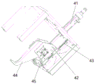
进一步地,所述钢瓶充装嘴精定位机构包括手抓升降气缸、滑动导向支架、滑轨、精定位手抓、手抓夹紧气缸,手抓升降气缸驱动连接滑动导向支架,滑动导向支架可在滑轨上滑动从而起到升降的作用,精定位手抓设于滑动导向支架的内部,精定位手抓端部呈镊子状并可开合夹接待充装钢瓶的瓶嘴,手抓夹紧气缸横向穿设于滑动导向支架和精定位手抓并可控制精定位手抓的开合。Further, the fine positioning mechanism for the filling nozzle of the steel cylinder includes a hand lifting cylinder, a sliding guide bracket, a slide rail, a fine positioning hand, and a hand clamping cylinder. The hand lifting cylinder is driven and connected to the sliding guide bracket, and the sliding guide bracket can be Sliding on the slide rail to play the role of lifting, the fine positioning hand grip is set inside the sliding guide bracket, the end of the fine positioning hand grip is in the shape of tweezers and can be opened and closed to clamp the mouth of the steel cylinder that is to be filled, and the grip is clamped The cylinder is transversely arranged on the sliding guide bracket and the fine positioning grip and can control the opening and closing of the fine positioning grip.
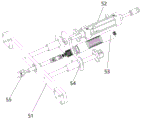
进一步地,所述钢瓶阀门自动锁紧机构包括支杆、锁紧升降气缸、锁紧电批、电批支架、锁紧手指,锁紧升降气缸设于支杆外侧,支杆外侧还设有电批支架,电批支架穿接锁紧电批,锁紧电批末端连接锁紧手指并可驱动其旋转,锁紧手指穿出支杆。Further, the cylinder valve automatic locking mechanism includes a support rod, a locking lifting cylinder, a locking electric screwdriver, an electric screwdriver bracket, and a locking finger. The batch bracket, the electric batch bracket is connected to the locking electric batch, the end of the locking electric batch is connected to the locking finger and can be driven to rotate, and the locking finger passes through the support rod.
进一步地,所述充装机构包括定位支架、充装管、推进气缸,所述推进气缸设于定位支架外侧,定位支架内侧设有充装管,充装管穿接于推进气缸并通过推进气缸驱动,充装管一端连接于所述充装阀座系统的阀管,另一端可对接待充装钢瓶的瓶嘴。Further, the filling mechanism includes a positioning bracket, a filling pipe, and a propelling cylinder. The propelling cylinder is arranged outside the positioning bracket, and a filling tube is provided inside the positioning bracket. The filling tube is connected to the propelling cylinder and passed through the propelling cylinder. Drive, one end of the filling pipe is connected to the valve pipe of the filling valve seat system, and the other end can be connected to the mouth of the steel cylinder to be filled.
本发明与现有技术相比,具有以下优点:Compared with the prior art, the present invention has the following advantages:
本发明一种冷媒介质的自动灌装设备,结构设计合理,组装拆卸方便,提高工作效率,运行稳定,安全可靠,准确化计量精度,适用于多种规格非重复充装制冷剂钢瓶的自动化充装。其高精度自动灌装阀组(充装阀组系统),冷媒粗加阀和冷媒精加阀的结合,可实现对不同规格制冷剂钢瓶的精准充装;压力传感器可对阀座内不同工作状态的压力进行监测,并实时发送给远程PLC控制器,对阀座的安全运行起到很好的保护作用;冷媒回收阀可对充装完成后的剩余冷媒进行回收,不仅节约冷媒,还可确保冷媒不外泄,避免环境污染。其通用气动控制阀,通过长期实践的检验,实现了多种规格冷媒介质的精确充装;具体地,所述阀盖调节帽的调整可用来适应不同规格冷媒介质的灌装压力;所述行程调节螺杆的设置可用来调节带有阀瓣组件的阀杆与冷媒进口阀芯之间的开合度;所述冷媒进口阀芯通过更换不同大小规格的孔口,来实现快速且高精度的冷媒介质灌装;所述冷媒阀体设有多个冷媒出口管接头,可实现对多个容器同时灌装。The invention is an automatic filling equipment for cold medium, which has reasonable structural design, convenient assembly and disassembly, improved work efficiency, stable operation, safety and reliability, accurate measurement accuracy, and is suitable for automatic filling of non-repeated refrigerant steel cylinders of various specifications. Pack. Its high-precision automatic filling valve group (filling valve group system), the combination of the refrigerant rough addition valve and the refrigerant fine addition valve can realize the precise filling of refrigerant steel cylinders of different specifications; The state pressure is monitored and sent to the remote PLC controller in real time, which plays a good role in protecting the safe operation of the valve seat; the refrigerant recovery valve can recover the remaining refrigerant after filling, which not only saves refrigerant, but also Ensure that the refrigerant does not leak out to avoid environmental pollution. Its universal pneumatic control valve, through long-term practice tests, has realized the accurate filling of various specifications of refrigerant media; specifically, the adjustment of the valve cover adjustment cap can be used to adapt to the filling pressure of different specifications of refrigerant media; the stroke The setting of the adjusting screw can be used to adjust the opening and closing degree between the valve stem with the disc assembly and the refrigerant inlet spool; the refrigerant inlet spool realizes fast and high-precision cooling of the refrigerant medium by replacing orifices of different sizes and specifications. Filling: The refrigerant valve body is provided with multiple refrigerant outlet pipe joints, which can realize simultaneous filling of multiple containers.
附图说明Description of drawings
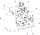
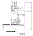
图1是本发明一种冷媒介质的自动灌装设备的整体结构示意图。Fig. 1 is a schematic diagram of the overall structure of an automatic filling equipment for cold medium according to the present invention.
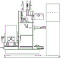
图2是本发明一种冷媒介质的自动灌装设备的侧面结构示意图。Fig. 2 is a side structural schematic diagram of an automatic filling device for cold medium according to the present invention.
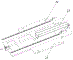
图3是本发明一种冷媒介质的自动灌装设备的滑动底座机构的结构示意图。Fig. 3 is a structural schematic diagram of a sliding base mechanism of an automatic filling equipment for cold medium according to the present invention.
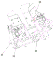
图4是本发明一种冷媒介质的自动灌装设备的钢瓶充装定位机构的结构示意图。Fig. 4 is a structural schematic diagram of a cylinder filling positioning mechanism of an automatic filling equipment for cold medium according to the present invention.
图5是本发明一种冷媒介质的自动灌装设备的钢瓶充装嘴精定位机构的结构示意图。Fig. 5 is a structural schematic diagram of a precise positioning mechanism of a steel cylinder filling nozzle of an automatic filling equipment for cold medium according to the present invention.
图6是本发明一种冷媒介质的自动灌装设备的钢瓶阀门自动锁紧机构的结构示意图。Fig. 6 is a structural schematic diagram of an automatic locking mechanism of a steel cylinder valve of an automatic filling equipment for cold medium according to the present invention.
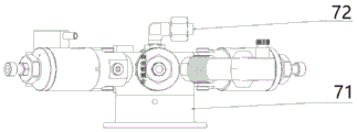
图7是本发明一种冷媒介质的高精度自动灌装阀组的整体结构示意图(一)。Fig. 7 is a schematic diagram (1) of the overall structure of a high-precision automatic filling valve group for cold medium according to the present invention.
图8是本发明一种冷媒介质的高精度自动灌装阀组的整体结构示意图(二)。Fig. 8 is a schematic diagram (2) of the overall structure of a high-precision automatic filling valve group for cold medium according to the present invention.
图9是本发明一种冷媒介质的高精度自动灌装阀组的工作原理示意图。Fig. 9 is a schematic diagram of the working principle of a high-precision automatic filling valve group for cold medium according to the present invention.
图10是本发明一种冷媒介质的自动灌装设备的充装机构的结构示意图。Fig. 10 is a structural schematic diagram of a filling mechanism of an automatic filling equipment for cold medium according to the present invention.
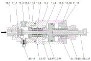
图11是本发明一种冷媒介质的通用气动控制阀的剖面结构示意图。Fig. 11 is a schematic cross-sectional structure diagram of a general pneumatic control valve for refrigerant medium according to the present invention.
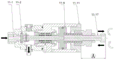
图12是本发明一种冷媒介质的通用气动控制阀通过行程调节螺杆来调整阀杆带动阀瓣组件与冷媒进口阀芯之间的开合度的示意图。Fig. 12 is a schematic diagram of a universal pneumatic control valve for refrigerant medium according to the present invention to adjust the opening and closing degree between the valve stem driving the disc assembly and the refrigerant inlet valve core through the stroke adjustment screw.
图13是本发明一种冷媒介质的通用气动控制阀通过阀盖调节帽的调整来适应不同冷媒介质压力的示意图。Fig. 13 is a schematic diagram of a universal pneumatic control valve of a refrigerant medium in the present invention adapting to different pressures of the refrigerant medium through the adjustment of the bonnet adjustment cap.
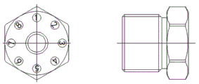
图14是本发明一种冷媒介质的通用气动控制阀的阀盖调节帽的结构示意图。Fig. 14 is a structural schematic diagram of a bonnet adjusting cap of a universal pneumatic control valve for refrigerant medium according to the present invention.
图15是本发明一种冷媒介质的自动灌装设备的工作原理图(一)。Fig. 15 is a working principle diagram (1) of an automatic filling equipment for cold medium according to the present invention.
图16是本发明一种冷媒介质的自动灌装设备的工作原理图(二)。Fig. 16 is a working principle diagram (2) of an automatic filling equipment for cold medium according to the present invention.
附图标记:1、称重系统;2、滑动底座机构;21、底座;22、滑动导轨;23、推动气缸;3、钢瓶充装定位机构;31、双层底盘;32、升降气缸;33、夹紧定位气缸;34、导向板;4、钢瓶充装嘴精定位机构;41、手抓升降气缸;42、滑动导向支架;43、滑轨;44、精定位手抓;45、手抓夹紧气缸;5、钢瓶阀门自动锁紧机构;51、支杆;52、锁紧升降气缸;53、锁紧电批;54、电批支架;55、锁紧手指;6、控制系统;7、充装阀组系统;71、阀座;72、冷媒灌装管;73、真空阀;74、冷媒粗加阀;75、冷媒精加阀;76、压力传感器;77、冷媒回收阀;7-8、真空电磁阀;7-9、真空负压表;7-10、二位三通电磁阀;7-11、真空泵;7-12、压缩空气源;7-13、四通管接头;7-14、冷媒物料总管;7-15、二位五通电磁阀;7-16、回收增压气缸;7-17、单向阀一;7-18、单向阀二;8、充装机构;81、定位支架;82、充装管;83、推进气缸;9、待充装钢瓶;101、支撑架一;102、支撑架二;11-1、冷媒进口阀芯;11-2、阀瓣组件;11-3、堵头;11-4、冷媒阀体;11-5、密封前压盖;11-6、密封;11-7、控制阀体;11-8、密封后压盖;11-9、控制阀活塞;11-10、排气孔;11-11、阀盖;11-12、泄露观察孔;11-13、进气孔;11-14、阀杆;11-15、压力调节弹簧;11-16、阀盖调节帽;11-17、行程调节螺杆。Reference signs: 1. weighing system; 2. sliding base mechanism; 21. base; 22. sliding guide rail; 23. pushing cylinder; 3. cylinder filling positioning mechanism; 31. double-layer chassis; 32. lifting cylinder; 33 , Clamping and positioning cylinder; 34, Guide plate; 4, Fine positioning mechanism of steel cylinder filling nozzle; 41, Hand lift cylinder; 42, Sliding guide bracket; 43, Slide rail; 44, Fine positioning hand grip; 45, Hand grip Clamping cylinder; 5. Cylinder valve automatic locking mechanism; 51. Strut; 52. Locking lifting cylinder; 53. Locking electric batch; 54. Electric batch bracket; 55. Locking finger; 6. Control system; 7 . Filling valve group system; 71. Valve seat; 72. Refrigerant filling pipe; 73. Vacuum valve; 74. Refrigerant rough addition valve; 75. Refrigerant fine addition valve; 76. Pressure sensor; -8. Vacuum solenoid valve; 7-9. Vacuum negative pressure gauge; 7-10. Two-position three-way solenoid valve; 7-11. Vacuum pump; 7-12. Compressed air source; 7-13. Four-way pipe joint; 7-14, refrigerant material main pipe; 7-15, two-position five-way solenoid valve; 7-16, recovery pressurized cylinder; 7-17, one-way valve one; 7-18, one-way valve two; 8, filling mechanism; 81, positioning bracket; 82, filling pipe; 83, propulsion cylinder; 9, steel cylinder to be filled; 101, support frame one; 102, support frame two; 11-1, refrigerant inlet valve core; Disc assembly; 11-3, plug; 11-4, refrigerant valve body; 11-5, sealing front gland; 11-6, sealing; 11-7, control valve body; 11-8, sealing rear gland ; 11-9, control valve piston; 11-10, exhaust hole; 11-11, valve cover; 11-12, leakage observation hole; 11-13, air intake hole; 11-14, valve stem; , Pressure adjustment spring; 11-16, bonnet adjustment cap; 11-17, stroke adjustment screw.
实施方式Implementation
下面结合附图,对本发明的实施例作进一步详细的描述。Embodiments of the present invention will be described in further detail below in conjunction with the accompanying drawings.
如图1、2所示,一种制冷剂自动灌装设备,包括台板一侧由下至上设置的称重系统1、滑动底座机构2、钢瓶充装定位机构3、钢瓶充装嘴精定位机构4、钢瓶阀门自动锁紧机构5和台板对侧的控制系统6、充装阀组系统7以及充装机构8,所述称重系统1承载滑动底座机构2以及支撑架,所述钢瓶充装定位机构3可在滑动底座机构2上来回滑动,所述钢瓶充装嘴精定位机构4和钢瓶阀门自动锁紧机构5通过支撑架悬设于待充装钢瓶9的上方,钢瓶阀门自动锁紧机构5位于钢瓶充装嘴精定位机构4的上方,所述充装机构8一端与充装阀组系统7连通,另一端可与待充装钢瓶9的瓶嘴连通,所述控制系统6操作控制称重系统1、滑动底座机构2、钢瓶充装定位机构3、钢瓶充装嘴精定位机构4、钢瓶阀门自动锁紧机构5、充装机构8和充装阀组系统7。As shown in Figures 1 and 2, an automatic refrigerant filling equipment includes a weighing
如图3所示,所述滑动底座机构2包括底座21、滑动导轨22和推动气缸23,底座21上排设成对的滑动导轨22,滑动导轨22之间设有推动气缸23,所述推动气缸23与所述钢瓶充装定位机构3的底部驱动连接。As shown in Fig. 3, described sliding
如图4所示,所述钢瓶充装定位机构3包括双层底盘31、升降气缸32和夹紧定位气缸33,升降气缸32设于双层底盘31中央,夹紧定位气缸33为四个并且呈十字对称设于双层底盘31周向。具体地,所述夹紧定位气缸33前置导向板34,夹紧定位气缸33驱动导向板34向内移动从而起到夹紧待充装钢瓶9的作用。As shown in Figure 4, the cylinder filling
如图5所示,所述钢瓶充装嘴精定位机构4包括手抓升降气缸41、滑动导向支架42、滑轨43、精定位手抓44、手抓夹紧气缸45,手抓升降气缸41驱动连接滑动导向支架42,滑动导向支架42可在滑轨43上滑动从而起到升降的作用,精定位手抓44设于滑动导向支架42的内部,精定位手抓44端部呈镊子状并可开合夹接待充装钢瓶9的瓶嘴,手抓夹紧气缸45横向穿设于滑动导向支架42和精定位手抓44并可控制精定位手抓44的开合。As shown in Figure 5, the
如图6所示,所述钢瓶阀门自动锁紧机构5包括支杆51、锁紧升降气缸52、锁紧电批53、电批支架54、锁紧手指55,锁紧电批53通过电批支架54固定连接,锁紧电批53末端连接锁紧手指55并可驱动其旋转,锁紧手指55穿出支杆51,锁紧手指55可夹接并旋转待充装钢瓶9的瓶嘴的充装阀,锁紧升降气缸52连接于电批支架54并驱动电批支架54升降。As shown in Figure 6, the cylinder valve
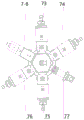
如图7、8所示,所述充装阀组系统7包括阀座71、冷媒灌装管72以及真空阀73、冷媒粗加阀74、冷媒精加阀75、压力传感器76、冷媒回收阀77,所述阀座71为可旋转五通阀座,所述冷媒灌装管72连通于阀座71,所述真空阀73、冷媒粗加阀74、冷媒精加阀75、冷媒回收阀77分别与阀座71相通并且分别通过二位三通电磁阀受控于控制系统6,所述压力传感器76与控制系统6通讯连接,所述冷媒粗加阀74、冷媒精加阀75、冷媒回收阀77的另一端分别通过四通管接头连接冷媒物料总管。具体地,压力传感器76用来监测阀座71内不同工作状态下的压力值,当所监测到的压力大于设定的压力阈值时,压力传感器76将信息传送给控制系统6,并通过控制系统6作出相应报警。As shown in Figures 7 and 8, the filling
如图9所示,所述真空阀73的另一端连接真空泵7-11,所述冷媒粗加阀74、冷媒精加阀75的另一端分别通过四通管接头7-13连接冷媒物料总管7-14并且分别外接压缩空气源7-12,所述压缩空气源7-12可分别为冷媒粗加阀74和冷媒精加阀75提供压缩空气,所述冷媒回收阀77通过回收增压气缸7-16与二位五通电磁阀7-15之间的调控连接于四通管接头7-13及冷媒物料总管7-14,所述回收增压气缸7-16前后分别设置单向阀。As shown in Figure 9, the other end of the
所述真空阀73还通过一真空电磁阀7-8连接到真空负压表7-9,所述真空负压表7-9与控制器6通讯连接,所述真空负压表7-9用来测定真空阀73内的真空度。Described
一种冷媒介质的高精度自动灌装阀组的工作原理如下:The working principle of a high-precision automatic filling valve group for cold medium is as follows:
步骤1),所述冷媒灌装管72与冷媒罐装钢瓶9对接密封,所述控制器6通过控制二位三通电磁阀7-10打开真空阀73,同时其它所有阀门处关闭状态,然后所述真空泵7-11对冷媒罐装钢瓶9进行抽真空,所述真空电磁阀7-8连接到真空负压表7-9并可实时测量真空度,当达到预设真空值时,所述真空负压表7-9反馈给控制器6,此时控制器6再次通过控制二位三通电磁阀7-10关闭真空阀73,抽真空完成;Step 1), the
步骤2),抽真空完成后,所述控制器6通过控制二位三通电磁阀7-10打开所述冷媒粗加阀74,同时其它所有阀门处关闭状态,冷媒从所述冷媒物料总管7-14经过四通管接头7-13进入冷媒粗加阀74,冷媒自动灌装开始,当达到预设重量值时,此时控制器6再次通过控制二位三通电磁阀7-10关闭所述冷媒粗加阀74,冷媒粗加完成;具体地,所述压缩空气源7-12将压缩空气输送到冷媒粗加阀74的控制腔从而关闭冷媒粗加阀74;Step 2), after the vacuuming is completed, the
步骤3),冷媒粗加完成后,所述控制器6通过控制二位三通电磁阀7-10打开所述冷媒精加阀75,同时其它所有阀门处关闭状态,冷媒从所述冷媒物料总管7-14经过四通管接头7-13进入冷媒精加阀75,冷媒精确自动灌装开始,当达到预设重量值时,此时控制器6再次通过控制二位三通电磁阀7-10关闭所述冷媒精加阀75,冷媒灌装完成;具体地,所述压缩空气源7-12将压缩空气输送到冷媒精加阀75的控制腔从而关闭冷媒精加阀75;Step 3), after the rough addition of refrigerant is completed, the
步骤4),冷媒灌装完成后,所述控制器6首先通过控制二位三通电磁阀7-10打开所述冷媒回收阀77,并确保其它所有阀门处关闭状态,同时所述控制器6再通过控制二位五通电磁阀7-15调控回收增压气缸7-16开始工作,当回收增压气缸7-16内的活塞向上挤压时,冷媒灌装管72以及可旋转五通阀座71内所剩的残余冷媒经过打开的冷媒回收阀77以及单向阀一7-17被抽回到回收增压气缸7-16内,当回收增压气缸7-16内的活塞向下挤压时,回收增压气缸7-16内残余冷媒经过单向阀二7-18被压回到冷媒物料总管7-14,冷媒回收完成;所述控制器6再次通过控制二位三通电磁阀7-10关闭所述冷媒回收阀77;Step 4), after the refrigerant filling is completed, the
至此,冷媒精确自动灌装的一个周期完成。So far, one cycle of precise and automatic refrigerant filling is completed.
如图10所示,所述充装机构8包括定位支架81、充装管82、推进气缸83,所述推进气缸83设于定位支架81外侧并靠近充装阀组系统7,定位支架81内侧设有充装管82,充装管82穿接于推进气缸83并通过推进气缸83驱动,充装管82一端连接于所述充装阀座系统7的阀管,另一端可对接待充装钢瓶9的瓶嘴的充装口。As shown in Figure 10, the
本发明的高精度自动灌装阀组中,所述冷媒粗加阀74、冷媒精加阀75均采用通用气动控制阀。如图11所示,本发明的通用气动控制阀,包括冷媒阀体11-4、控制阀体11-7以及冷媒阀体11-4与控制阀体11-7之间的密封组件,一阀杆11-14依次贯穿冷媒阀体11-4、密封组件和控制阀体11-7。所述冷媒阀体11-4前口穿接冷媒进口阀芯11-1,冷媒阀体11-4内且端部套接阀瓣组件11-2的阀杆部分与冷媒进口阀芯11-1可开合相连,阀瓣组件11-2与冷媒阀体11-4内阀杆部分通过自由活动的销钉连接,从而确保与冷媒进口阀芯11-1的零泄漏长时间密封。所述冷媒阀体11-4一侧设有冷媒出口管接头11-18,另一侧设有堵头11-3,所述冷媒出口管接头11-18朝下,所述堵头11-3朝上。所述控制阀体11-7内阀杆部分端部套接控制阀活塞11-9,控制阀体11-7后口通过一阀盖11-11闭合,所述阀盖11-11开设排气孔11-10,阀盖11-11内可活动螺接阀盖调节帽11-16,阀盖调节帽11-16可活动螺接行程调节螺杆11-17,所述行程调节螺杆11-17穿套压力调节弹簧11-15,所述压力调节弹簧11-15伸入所述阀盖调节帽11-16与行程调节螺杆11-17之间的间隙,所述控制阀活塞11-9带动阀杆11-14与行程调节螺杆11-17可开合相连。所述控制阀体11-7一侧开设进气孔11-13。In the high-precision automatic filling valve group of the present invention, the refrigerant
所述密封组件包括密封前压盖11-5、密封后压盖11-8以及密封前压盖11-5与密封后压盖11-8之间的若干道密封11-6,密封11-6之间设有一泄露观察孔11-12。具体地,设有四道密封11-6,两道密封11-6为一组,密封11-6组之间设有孔口,该孔口与所述泄露观察孔11-12相连。当发现泄露观察孔11-12有泄露时,说明前两道密封11-6有泄露,但还有后两道密封11-6,这样也不影响正常灌装,安排合适时间维修即可。The sealing assembly includes a sealing front gland 11-5, a sealing rear gland 11-8, and several seals 11-6 between the sealing front gland 11-5 and the sealing rear gland 11-8, and the sealing 11-6 There is a leakage observation hole 11-12 between them. Specifically, four seals 11-6 are provided, two seals 11-6 form a group, and an orifice is provided between the groups of seals 11-6, and the orifice is connected to the leakage observation hole 11-12. When it is found that the leakage observation hole 11-12 leaks, it means that the first two seals 11-6 have leaks, but there are also the rear two seals 11-6, which does not affect the normal filling, and can be repaired at an appropriate time.
所述冷媒进口阀芯11-1有若干种规格,不同规格对应不同的冷媒进口阀芯11-1孔口大小。所述冷媒进口阀芯11-1孔口的大小,决定了冷媒介质的流量大小,阀芯孔口越大,则流量相对越大,阀芯孔口越小,则流量相对越小。所述冷媒进口阀芯11-1安装拆卸方便,更换为小孔径时,则为精加控制阀,更换为大孔径时,则为粗加控制阀。当精加控制阀与粗加控制阀组成一组控制阀时,即可实现快速且高精度的冷媒介质灌装。The refrigerant inlet valve core 11-1 has several specifications, and different specifications correspond to different orifice sizes of the refrigerant inlet valve core 11-1. The size of the orifice of the refrigerant inlet spool 11-1 determines the flow rate of the refrigerant medium. The larger the orifice of the spool, the larger the flow, and the smaller the orifice of the spool, the smaller the flow. The refrigerant inlet spool 11-1 is easy to install and disassemble. If it is replaced with a small aperture, it will be a finishing control valve, and if it is replaced with a large aperture, it will be a roughing control valve. When the finishing control valve and the roughing control valve form a set of control valves, fast and high-precision filling of cold medium can be realized.
所述冷媒阀体11-4上设有若干个冷媒出口管接头11-18,可实现对多个容器同时灌装。The refrigerant valve body 11-4 is provided with several refrigerant outlet pipe joints 11-18, which can realize simultaneous filling of multiple containers.
当压力调节弹簧11-15与带动阀杆11-14的控制阀活塞11-9相抵时,即压力调节弹簧11-15一端与控制阀活塞11-9相抵,而此时行程调节螺杆11-17并不与控制阀活塞11-9相抵,行程调节螺杆11-17与控制阀活塞11-9之间具有一定间距,这个间距可供阀杆11-14带动阀瓣组件11-2与冷媒进口阀芯11-1的开合。如图12所示,阀杆11-14带动阀瓣组件11-2与冷媒进口阀芯11-1之间的开合度,通过微调长度值A(行程调节螺杆11-17伸出阀盖11-11部分的长度值)来控制;当所述行程调节螺杆11-17按逆时针旋转时,则行程调节螺杆11-17向右移动,长度值A增大,开合度增大;当所述行程调节螺杆11-17按顺时针旋转时,则行程调节螺杆11-17向左移动,长度值A减小,开合度减小。When the pressure adjustment spring 11-15 is offset against the control valve piston 11-9 that drives the valve rod 11-14, that is, one end of the pressure adjustment spring 11-15 is offset against the control valve piston 11-9, and at this time the stroke adjustment screw rod 11-17 Not offset against the control valve piston 11-9, there is a certain distance between the stroke adjustment screw 11-17 and the control valve piston 11-9, this distance can be used by the valve stem 11-14 to drive the disc assembly 11-2 and the refrigerant inlet valve Opening and closing of the core 11-1. As shown in Figure 12, the valve rod 11-14 drives the opening and closing degree between the valve clack assembly 11-2 and the refrigerant inlet valve core 11-1. 11 part length value) to control; when the stroke adjustment screw 11-17 rotates counterclockwise, the stroke adjustment screw 11-17 moves to the right, the length value A increases, and the opening and closing degree increases; when the stroke When the adjustment screw rod 11-17 rotates clockwise, the stroke adjustment screw rod 11-17 moves to the left, the length value A decreases, and the opening and closing degree decreases.
本发明一种冷媒介质的通用气动控制阀,常态下为常闭阀,所述压力调节弹簧11-15用来提供压力。如图13所示,具体地,阀盖11-11与阀盖调节帽11-16以及控制阀活塞11-9构成压力调节弹簧11-15的预压紧量,通过微调B长度值(阀盖调节帽11-16伸出阀盖11-11部分的长度值)来控制压力调节弹簧11-15的预紧力,从而适应不同冷媒介质的压力;为避免冷媒介质误入冷媒进口阀芯11-1,即要使得压力调节弹簧11-15顶住带动阀杆11-14的控制阀活塞11-9的压力大于等于冷媒介质的压力;当冷媒介质压力低时,则阀盖调节帽11-16按逆时针旋转,长度值B增大,压力调节弹簧11-15的预紧力随之减小;当冷媒介质压力高时,则阀盖调节帽11-16按顺时针旋转,长度值B减小,压力调节弹簧11-15的预紧力随之增大。如图14所示,所述阀盖调节帽11-16外周面上刻有均布八等分的刻度值,所述阀盖调节帽11-16的螺距为2mm,每转1/8圈,其调整的长度值B为0.25mm,满足压力调节精度的要求。The present invention is a general pneumatic control valve for cold medium, which is a normally closed valve under normal conditions, and the pressure regulating springs 11-15 are used to provide pressure. As shown in Figure 13, specifically, the bonnet 11-11, the bonnet adjusting cap 11-16 and the control valve piston 11-9 constitute the preloading amount of the pressure regulating spring 11-15, by fine-tuning the B length value (bonnet Adjust the length of the cap 11-16 extending out of the bonnet 11-11) to control the pre-tightening force of the pressure adjustment spring 11-15, so as to adapt to the pressure of different refrigerant media; in order to prevent the refrigerant from entering the refrigerant inlet spool 11- 1. That is to make the pressure regulating spring 11-15 withstand the pressure of the control valve piston 11-9 that drives the valve stem 11-14 to be greater than or equal to the pressure of the refrigerant medium; when the pressure of the refrigerant medium is low, the bonnet adjustment cap 11-16 Rotate counterclockwise, the length value B increases, and the pretightening force of the pressure adjustment spring 11-15 decreases accordingly; when the pressure of the refrigerant medium is high, the bonnet adjustment cap 11-16 rotates clockwise, and the length value B decreases Small, the pretightening force of pressure adjustment spring 11-15 increases thereupon. As shown in Fig. 14, the scale value of evenly distributed eight equal divisions is engraved on the outer peripheral surface of the bonnet adjusting cap 11-16, and the pitch of the bonnet adjusting cap 11-16 is 2 mm, and every 1/8 turn, The adjusted length B is 0.25mm, which meets the requirement of pressure regulation accuracy.
本发明一种冷媒介质的通用气动控制阀,其工作原理如下:(一)当冷媒介质需要灌装时,所述进气孔11-13开始压入压缩空气,压缩空气的压力大于所述压力调节弹簧11-15的弹簧力,压缩空气的压力推动所述控制阀活塞11-9从而带动阀杆11-14以及阀瓣组件11-2向阀盖11-11方向移动,移动的同时阀盖11-11开设的排气孔11-10进行排气,直到控制阀活塞11-9撞上所述行程调节螺杆11-17,此时所述冷媒进口阀芯11-1与带有阀瓣组件11-2的阀杆11-14脱离分开,冷媒介质通过冷媒进口阀芯11-1进入冷媒阀体11-4内并瞬间充满腔体,然后冷媒介质从所述冷媒出口管接头11-18处进入需要灌装的容器内。(二)灌装完成后,所述进气孔11-13开始泄压,所述压力调节弹簧11-15推动所述控制阀活塞11-9带动阀杆11-14以及阀瓣组件11-2向冷媒进口阀芯11-1方向移动,所述冷媒进口阀芯11-1与带有阀瓣组件11-2的阀杆11-14闭合,一次灌装完成,准备下一次灌装。The present invention is a universal pneumatic control valve for cold medium, and its working principle is as follows: (1) When the cold medium needs to be filled, the air intake holes 11-13 start to press compressed air, and the pressure of the compressed air is greater than the pressure Adjust the spring force of the spring 11-15, and the pressure of the compressed air pushes the control valve piston 11-9 to drive the valve stem 11-14 and the disc assembly 11-2 to move towards the valve cover 11-11, and the valve cover moves at the same time The exhaust hole 11-10 opened in 11-11 is exhausted until the control valve piston 11-9 bumps into the stroke adjustment screw 11-17. At this time, the refrigerant inlet spool 11-1 and the disc assembly The valve stem 11-14 of 11-2 is detached and separated, and the refrigerant medium enters the refrigerant valve body 11-4 through the refrigerant inlet valve core 11-1 and fills the cavity instantly, and then the refrigerant medium is released from the refrigerant outlet pipe joint 11-18. into the container to be filled. (2) After the filling is completed, the air inlet 11-13 starts to release pressure, and the pressure regulating spring 11-15 pushes the control valve piston 11-9 to drive the valve stem 11-14 and the valve disc assembly 11-2 Move toward the direction of the refrigerant inlet valve core 11-1, the refrigerant inlet valve core 11-1 is closed with the valve stem 11-14 with the disc assembly 11-2, one filling is completed, and the next filling is ready.
对于一种冷媒介质的自动灌装设备,具体地,所述支撑架包括支撑架一101和支撑架二102。所述支撑架一101架设于所述滑动底座机构2的底座21上并位于成对滑动导轨22的外侧,支撑架一101包括四根立柱和四根立柱顶部的正方形框,一侧的立柱之间设有加强柱。所述支撑架二102架设于所述支撑架一101的正方形框上,支撑架二102包括四根立柱和四根立柱顶部的正方形板,正方形板中心镂空。所述钢瓶充装定位机构3带动待充装钢瓶9滑动到待充装区域,即支撑架一101内部;所述钢瓶充装嘴精定位机构4的手抓升降气缸41垂直穿接所述支撑架二102的正方形板,其滑轨43设于支撑架二102一侧的架板上,其精定位手抓44的端部伸入所述支撑架一101内部并对准待充装钢瓶9的瓶嘴;所述钢瓶阀门自动锁紧机构5的支杆51架设于所述支撑架一101的正方形框上,锁紧电批53穿入所述支撑架二102的正方形板中心的镂空处并固定连接于电批支架54,锁紧电批53连接锁紧手指55,锁紧手指55穿接支杆51并对准待充装钢瓶9的瓶嘴的充装阀,锁紧升降气缸52穿入所述支撑架二102的正方形板并固定连接于电批支架54,锁紧升降气缸52驱动电批支架54升降,电批支架54可沿固定连接于所述支撑架二102的正方形板上的两个导向支柱滑动;所述充装机构8的定位支架81通过架板固定连接于所述支撑架一101外侧两根立柱上,充装管82穿入架板后伸入所述支撑架一101内部并对准待充装钢瓶9的瓶嘴的充装口。For an automatic filling device for cold medium, specifically, the support frame includes a support frame one 101 and a support frame two 102 . The support frame one 101 is erected on the
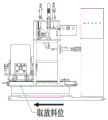
需要说明的是,本发明中的待充装钢瓶9为非重复充装制冷剂钢瓶,待充装钢瓶9由长方体包装盒包裹并露出瓶嘴部分,图15为总设备处于取放料工位的工作原理示意图,图16为总设备处于充装工位的工作原理示意图。It should be noted that the
本发明的一种制冷剂自动灌装设备的工作原理为:The working principle of a kind of refrigerant automatic filling equipment of the present invention is:
第一步,所述钢瓶充装定位机构3在取放料工位时,如图15所示,待充装钢瓶9经机械臂自动抓取放入钢瓶充装定位机构3,此时钢瓶充装定位机构3中的传感器感应到待充装钢瓶9,其夹紧定位气缸33即刻夹紧待充装钢瓶9;In the first step, when the steel cylinder filling
第二步,所述滑动底座机构2通过其推动气缸23、滑动导轨22将钢瓶充装定位机构3以及待充装钢瓶9推送到所述滑动底座机构2的充装工位,如图16所示;In the second step, the sliding
第三步,所述钢瓶充装定位机构3及待充装钢瓶9到位后,所述钢瓶充装嘴精定位机构4中的精定位手爪44通过手爪升降气缸41下降到待充装钢瓶9的瓶嘴位置,随后手爪夹紧气缸45将瓶嘴夹紧,起到对待充装钢瓶9的瓶嘴的精确定位作用;In the third step, after the steel cylinder filling
第四步,待充装钢瓶9的瓶嘴定位完成后,所述充装机构8开始执行动作,充装机构8的充装管82通过推进气缸83推进直到与精确定位的瓶嘴的充装口对接并密封;In the fourth step, after the positioning of the mouth of the filled
第五步,所述充装机构8的充装管82与待充装钢瓶9的瓶嘴的充装口对接后,所述充装阀组系统7开始工作,所述称重系统1与所述充装阀组系统7相互配合并实时交互,所述充装阀组系统7的真空阀73对待充装钢瓶9进行抽真空,其冷媒粗加阀74对待充装钢瓶9进行大流量灌装,其冷媒精加阀75对待充装钢瓶9进行小流量精确灌装,充装完成后其冷媒回收阀77对所述充装机构8的充装管82进行冷媒物料回收;In the fifth step, after the filling
第六步,冷媒物料回收完成后,所述钢瓶阀门自动锁紧机构5开始工作,其锁紧手指55通过锁紧升降气缸52和电批支架54及导向支柱,下降至待充装钢瓶9的瓶嘴的充装阀处,所述锁紧电批53带动锁紧手指55将充装阀锁紧,至此待充装钢瓶9充装完成。In the sixth step, after the recovery of the refrigerant material is completed, the cylinder valve
充装完成后,所有机构开始回退:第一步,所述锁紧升降气缸52将所述钢瓶阀门自动锁紧机构5上升回退;第二步,所述充装机构8通过其推进气缸83回退;第三步,所述钢瓶充装嘴精定位机构4松开精定位手爪44,同时手爪升降气缸41上升回退;第四步,所述钢瓶充装定位机构3通过所述滑动底座机构2的推动气缸23及滑动导轨22回退到图15所示的取放料工位;第五步,所述钢瓶充装定位机构3中的夹紧定位气缸33松开回退。至此,所有机构完成一次制冷剂充装动作,所有机构部件返回到初始位置,等待下一次充装。After the filling is completed, all mechanisms start to retreat: the first step, the locking and lifting
以上所述仅是本发明优选实施方式,应当指出,对于本技术领域的普通技术人员,在不脱离本发明构思的前提下,还可以做出若干改进和润饰,这些改进和润饰也应视为本发明保护范围内。The above is only a preferred embodiment of the present invention, it should be pointed out that for those of ordinary skill in the art, without departing from the concept of the present invention, some improvements and modifications can also be made, and these improvements and modifications should also be regarded as Within the protection scope of the present invention.
Claims (8)
Applications Claiming Priority (2)
| Application Number | Priority Date | Filing Date | Title |
|---|---|---|---|
| CN2022113863225 | 2022-11-07 | ||
| CN202211386322 | 2022-11-07 |
Publications (1)
| Publication Number | Publication Date |
|---|---|
| CN116123767A true CN116123767A (en) | 2023-05-16 |
Family
ID=86309949
Family Applications (1)
| Application Number | Title | Priority Date | Filing Date |
|---|---|---|---|
| CN202310138591.8A Pending CN116123767A (en) | 2022-11-07 | 2023-02-20 | Universal pneumatic control valve for refrigerant medium, high-precision automatic filling valve group and automatic filling equipment |
Country Status (1)
| Country | Link |
|---|---|
| CN (1) | CN116123767A (en) |
Citations (7)
| Publication number | Priority date | Publication date | Assignee | Title |
|---|---|---|---|---|
| JP2000346497A (en) * | 1999-06-09 | 2000-12-15 | Mitsubishi Electric Corp | On-off valve for refrigeration cycle device and refrigeration cycle device provided with the on-off valve |
| CN1665718A (en) * | 2002-05-06 | 2005-09-07 | 美国Boc氧气集团有限公司 | Chemical mix and delivery systems and methods thereof |
| CN204153292U (en) * | 2014-09-10 | 2015-02-11 | 武汉汉德阀门仪表有限公司 | Multifunction burning gas control valve |
| CN104864262A (en) * | 2015-06-08 | 2015-08-26 | 扬州美达灌装机械有限公司 | Full-automatic tri-head linear type under-cover filling machine |
| CN209655017U (en) * | 2019-01-28 | 2019-11-19 | 余姚市超成机械制造有限公司 | A kind of steel cylinder automatic filling equipment |
| CN216887482U (en) * | 2021-12-27 | 2022-07-05 | 天津市长龙宏业燃气设备有限公司 | Steel cylinder positioning device for refrigerant filling machine and refrigerant filling machine |
| CN220037462U (en) * | 2022-11-07 | 2023-11-17 | 浙江巨化装备工程集团有限公司 | Universal pneumatic control valve for refrigerant medium |
-
2023
- 2023-02-20 CN CN202310138591.8A patent/CN116123767A/en active Pending
Patent Citations (7)
| Publication number | Priority date | Publication date | Assignee | Title |
|---|---|---|---|---|
| JP2000346497A (en) * | 1999-06-09 | 2000-12-15 | Mitsubishi Electric Corp | On-off valve for refrigeration cycle device and refrigeration cycle device provided with the on-off valve |
| CN1665718A (en) * | 2002-05-06 | 2005-09-07 | 美国Boc氧气集团有限公司 | Chemical mix and delivery systems and methods thereof |
| CN204153292U (en) * | 2014-09-10 | 2015-02-11 | 武汉汉德阀门仪表有限公司 | Multifunction burning gas control valve |
| CN104864262A (en) * | 2015-06-08 | 2015-08-26 | 扬州美达灌装机械有限公司 | Full-automatic tri-head linear type under-cover filling machine |
| CN209655017U (en) * | 2019-01-28 | 2019-11-19 | 余姚市超成机械制造有限公司 | A kind of steel cylinder automatic filling equipment |
| CN216887482U (en) * | 2021-12-27 | 2022-07-05 | 天津市长龙宏业燃气设备有限公司 | Steel cylinder positioning device for refrigerant filling machine and refrigerant filling machine |
| CN220037462U (en) * | 2022-11-07 | 2023-11-17 | 浙江巨化装备工程集团有限公司 | Universal pneumatic control valve for refrigerant medium |
Non-Patent Citations (1)
| Title |
|---|
| 李国荣: "《石油地质勘探综合实训指导书》", 31 December 2016, 西北工业大学出版社, pages: 173 * |
Similar Documents
| Publication | Publication Date | Title |
|---|---|---|
| CN109556808B (en) | A fuel cell stack automated air tightness testing equipment and testing method | |
| CN204905350U (en) | Battery filling device | |
| CN117169101B (en) | Corrosion resistance detection device for plastic film | |
| CN207705295U (en) | Lithium battery equipressure priming device | |
| CN102701124A (en) | High-fitness and high-reliability cap screwing method and device thereof | |
| CN107834017A (en) | Lithium battery equipressure priming device and its electrolyte filling method | |
| CN107192546A (en) | A kind of gas high pressure valve high-potting system | |
| CN209570309U (en) | A fuel cell stack automatic air tightness testing equipment | |
| CN214653568U (en) | A gas filling valve | |
| CN116123767A (en) | Universal pneumatic control valve for refrigerant medium, high-precision automatic filling valve group and automatic filling equipment | |
| CN208313722U (en) | A kind of U heat exchange pressure testing device | |
| CN114477054B (en) | Refrigerant production filling equipment and use method thereof | |
| CN117007251A (en) | GRV valve performance detection method and detection device | |
| CN109524258B (en) | Isobaric vacuumizing and inflating device of power switch and control method thereof | |
| CN220034004U (en) | Automatic filling equipment of refrigerant | |
| CN107654718A (en) | A kind of two-part pneumatic valve group filling for big flow and packaging process | |
| CN208665663U (en) | Precisely open bag package machine structure | |
| CN215944954U (en) | Dust raising prevention device at discharge port of powder packaging scale | |
| CN206092371U (en) | Water pump test board | |
| CN214521431U (en) | Full-automatic lens casting machine | |
| CN209783827U (en) | A gas filled structure for detecting airtight performance test | |
| CN209717091U (en) | Fixtures for machine tool fixtures | |
| CN206223246U (en) | A kind of device for measuring inside battery spatial volume | |
| CN209205335U (en) | A kind of more test tube sealing devices | |
| CN217391452U (en) | Fixing support for inflating liquid carbon dioxide fire extinguisher |
Legal Events
| Date | Code | Title | Description |
|---|---|---|---|
| PB01 | Publication | ||
| PB01 | Publication | ||
| SE01 | Entry into force of request for substantive examination | ||
| SE01 | Entry into force of request for substantive examination |