CN116196673A - Slag-water separation device and cleaning machine - Google Patents
Slag-water separation device and cleaning machine Download PDFInfo
- Publication number
- CN116196673A CN116196673A CN202111461018.8A CN202111461018A CN116196673A CN 116196673 A CN116196673 A CN 116196673A CN 202111461018 A CN202111461018 A CN 202111461018A CN 116196673 A CN116196673 A CN 116196673A
- Authority
- CN
- China
- Prior art keywords
- slag
- water
- separation device
- water separation
- push plate
- Prior art date
- Legal status (The legal status is an assumption and is not a legal conclusion. Google has not performed a legal analysis and makes no representation as to the accuracy of the status listed.)
- Granted
Links
Images



Classifications
-
- B—PERFORMING OPERATIONS; TRANSPORTING
- B01—PHYSICAL OR CHEMICAL PROCESSES OR APPARATUS IN GENERAL
- B01D—SEPARATION
- B01D29/00—Filters with filtering elements stationary during filtration, e.g. pressure or suction filters, not covered by groups B01D24/00 - B01D27/00; Filtering elements therefor
- B01D29/11—Filters with filtering elements stationary during filtration, e.g. pressure or suction filters, not covered by groups B01D24/00 - B01D27/00; Filtering elements therefor with bag, cage, hose, tube, sleeve or like filtering elements
- B01D29/31—Self-supporting filtering elements
- B01D29/35—Self-supporting filtering elements arranged for outward flow filtration
-
- B—PERFORMING OPERATIONS; TRANSPORTING
- B01—PHYSICAL OR CHEMICAL PROCESSES OR APPARATUS IN GENERAL
- B01D—SEPARATION
- B01D29/00—Filters with filtering elements stationary during filtration, e.g. pressure or suction filters, not covered by groups B01D24/00 - B01D27/00; Filtering elements therefor
- B01D29/50—Filters with filtering elements stationary during filtration, e.g. pressure or suction filters, not covered by groups B01D24/00 - B01D27/00; Filtering elements therefor with multiple filtering elements, characterised by their mutual disposition
- B01D29/56—Filters with filtering elements stationary during filtration, e.g. pressure or suction filters, not covered by groups B01D24/00 - B01D27/00; Filtering elements therefor with multiple filtering elements, characterised by their mutual disposition in series connection
-
- B—PERFORMING OPERATIONS; TRANSPORTING
- B01—PHYSICAL OR CHEMICAL PROCESSES OR APPARATUS IN GENERAL
- B01D—SEPARATION
- B01D29/00—Filters with filtering elements stationary during filtration, e.g. pressure or suction filters, not covered by groups B01D24/00 - B01D27/00; Filtering elements therefor
- B01D29/76—Handling the filter cake in the filter for purposes other than for regenerating
-
- B—PERFORMING OPERATIONS; TRANSPORTING
- B01—PHYSICAL OR CHEMICAL PROCESSES OR APPARATUS IN GENERAL
- B01D—SEPARATION
- B01D29/00—Filters with filtering elements stationary during filtration, e.g. pressure or suction filters, not covered by groups B01D24/00 - B01D27/00; Filtering elements therefor
- B01D29/76—Handling the filter cake in the filter for purposes other than for regenerating
- B01D29/80—Handling the filter cake in the filter for purposes other than for regenerating for drying
- B01D29/82—Handling the filter cake in the filter for purposes other than for regenerating for drying by compression
Landscapes
- Chemical & Material Sciences (AREA)
- Chemical Kinetics & Catalysis (AREA)
- Processing Of Solid Wastes (AREA)
Abstract
本发明涉及一种渣水分离装置及清洗机,该渣水分离装置包括壳体和推板,壳体内部中空形成容腔,该容腔具有进水口、出水口和排出口,进水口位于排出口的斜上方并排出口相互错位,推板设于容腔内且布置在进水口的下方,通过容腔的进水口和出水口的共同作用,能够顺利的完成余水的排出功能,且其中的进水口和排出口的交错布置形式,可以将残渣的收集动作与排水动作分隔开来进行分别处理,同时利用推板的间歇推动,能够在需要时驱动推板进行残渣的集中处理,相比于传统的直排形式,垃圾处理方式更加灵活,残渣的储存不再受限于竖向的排出结构,无论是对残渣进行后续的烘干还是收集,都更加的方便,十分实用。

The invention relates to a slag-water separation device and a cleaning machine. The slag-water separation device includes a shell and a push plate. The inside of the shell is hollow to form a cavity. The cavity has a water inlet, a water outlet and a discharge port. The oblique upper part of the outlet and the discharge port are misaligned with each other. The push plate is set in the cavity and arranged below the water inlet. The staggered arrangement of water inlets and outlets can separate the residue collection action from the drainage action for separate treatment, and at the same time use the intermittent push of the push plate to drive the push plate for centralized treatment of residue when needed. Compared with the traditional straight discharge method, the garbage disposal method is more flexible, and the storage of residues is no longer limited by the vertical discharge structure. Whether it is subsequent drying or collection of residues, it is more convenient and very practical.
Description
技术领域technical field
本发明涉及厨余垃圾清理领域,具体属于一种渣水分离装置及清洗机。The invention relates to the field of kitchen waste cleaning, in particular to a slag-water separation device and a washing machine.
背景技术Background technique
随着人们环保意识的增加,对垃圾分类的重视程度也越来越高,厨余垃圾作为日常垃圾的一大类,需要专门的处理方式,如果不及时倾倒,尤其是夏日,不仅容易滋生细菌蚊虫,也会产生难闻的气味。为此,很多人选择的较为方便的垃圾处理器来应对厨余垃圾的处理。目前市场上的垃圾处理器多为直排式,即一般安装在水槽下水口位置,厨余垃圾倒进垃圾处理器内进行切割搅拌,然后向下水管道内排放掉,这样一来容易造成下水管道的堵塞,如果整个小区内安装该直排式垃圾处理器较多,将给小区排水管带来堵塞问题,为此部分企业公司研发了带有烘干功能的垃圾处理器。With the increase of people's awareness of environmental protection, the importance of garbage classification is getting higher and higher. Kitchen waste, as a major category of daily garbage, needs special treatment methods. If it is not dumped in time, especially in summer, it will not only easily breed Bacteria mosquitoes also produce unpleasant odors. For this reason, many people choose more convenient garbage disposers to deal with kitchen waste. At present, most of the garbage disposers on the market are in-line type, that is, they are generally installed at the sink outlet of the sink. The kitchen waste is poured into the garbage disposer for cutting and mixing, and then discharged into the sewer pipe, which is easy to cause damage to the sewer pipe. If there are many direct discharge garbage disposers installed in the entire community, it will cause blockage to the drainage pipes of the community. For this reason, some companies have developed garbage disposers with drying functions.
例如专利号为CN201921630698.X的中国实用新型专利就公开了《一种厨房垃圾处理器》,在起固定盖的上部铰接有外盖,外盖中设有触控按钮,该触控按钮与控制盒连接,控制盒固定在主体外壳内部下方;控制盒上方的主体外壳中嵌设有粉碎腔体,固定盖嵌设在粉碎腔体的上端口中,固定盖的周边搭设在厨房台面的上表面,粉碎腔体的内壁上部贯通连接有清洗喷头,该清洗喷头与入水管贯通连接,入水管的入口端穿过主体外壳的下侧壁后,与厨房水源连接,该入水管上设有电磁阀,该电磁阀与控制盒连接。For example, the Chinese utility model patent whose patent number is CN201921630698.X discloses "a kind of kitchen garbage disposer". An outer cover is hinged on the upper part of the fixed cover, and a touch button is arranged in the outer cover. Box connection, the control box is fixed below the inside of the main shell; the main shell above the control box is embedded with a crushing cavity, the fixed cover is embedded in the upper port of the crushing cavity, and the periphery of the fixed cover is set on the upper surface of the kitchen countertop , the upper part of the inner wall of the crushing chamber is connected with a cleaning nozzle, the cleaning nozzle is connected with the water inlet pipe, the inlet end of the water inlet pipe passes through the lower side wall of the main body shell, and is connected to the kitchen water source, and the water inlet pipe is provided with a solenoid valve , the solenoid valve is connected with the control box.
虽然在兼具厨余垃圾粉碎的功能之外,该垃圾处理器还具有渣水分离的功效,有效降低下水道堵塞情况的发生率,但是类似的垃圾处理器能够满足余水较少的厨余垃圾诸如菜叶、剩饭、剩菜等,对于余水较多的不易处理,且直排式的垃圾处理器,其处理后待回收的残渣不易收集,使用不便。Although in addition to the function of crushing kitchen waste, the garbage disposer also has the effect of separating slag and water, effectively reducing the incidence of sewer blockage, but similar garbage disposers can meet the needs of kitchen waste with less residual water. Such as vegetable leaves, leftovers, leftovers, etc., are not easy to handle for those with a lot of residual water, and the in-line garbage disposer is not easy to collect the residue to be recycled after processing, and it is inconvenient to use.
发明内容Contents of the invention
本发明所要解决的第一个技术问题是针对现有技术的现状,提供一种利于残渣收集的渣水分离装置。The first technical problem to be solved by the present invention is to provide a slag-water separation device that facilitates slag collection in view of the current state of the art.
本发明所要解决的第二个技术问题是针对现有技术的现状,提供一种有效挤压残渣以排出余水的渣水分离装置。The second technical problem to be solved by the present invention is to provide a slag-water separation device that can effectively squeeze the slag to discharge the residual water in view of the current state of the art.
本发明所要解决的第三个技术问题是针对现有技术的现状,提供一种具有上述渣水分离装置的清洗机。The third technical problem to be solved by the present invention is to provide a washing machine with the above-mentioned slag-water separation device in view of the current state of the art.
本发明解决上述第一个技术问题所采用的技术方案为:一种渣水分离装置,包括:The technical solution adopted by the present invention to solve the above-mentioned first technical problem is: a slag-water separation device, comprising:
壳体,内部中空形成容腔,所述容腔具有出水口、用来与水槽腔体相连通的进水口以及用来与下游研磨器相连通的排出口,沿着流体的流动方向,所述出水口布置在进水口的下游;The housing is hollow inside to form a cavity, and the cavity has a water outlet, a water inlet used to communicate with the tank cavity, and a discharge port used to communicate with the downstream grinder. Along the flow direction of the fluid, the The water outlet is arranged downstream of the water inlet;
所述进水口位于所述排出口的斜上方并与所述排出口相互错位,还包括有:The water inlet is located obliquely above the discharge port and is misaligned with the discharge port, and further includes:
推板,设于所述容腔内且布置在所述进水口的下方,该推板能靠近或者远离所述排出口,并在靠近所述排出口的状态下将残渣推送至所述排出口处。a push plate, arranged in the cavity and below the water inlet, the push plate can approach or stay away from the discharge port, and push the residue to the discharge port when it is close to the discharge port place.
为了确保渣水分离装置排水顺畅,优选地,所述容腔包括用来收集残渣的收集腔室以及与收集腔室并排布置的沥水腔室,所述进水口和出水口均布置在沥水腔室,所述出水口位于所述进水口的下方且与所述进水口贯通形成沥水流道,所述排出口布置在收集腔室处,这样出水口与进水口的布局形式,使得沥水流道在竖向上形成贯通,需要排出的余水不会被任何形式的部件阻挡,确保了排水顺畅。In order to ensure smooth drainage of the slag-water separation device, preferably, the cavity includes a collection chamber for collecting residues and a drainage chamber arranged side by side with the collection chamber, and the water inlet and outlet are both arranged in the drainage chamber , the water outlet is located below the water inlet and connects with the water inlet to form a drainage channel, and the outlet is arranged at the collection chamber, so that the layout of the water outlet and the water inlet makes the drainage channel in the The vertical connection is formed, and the remaining water that needs to be discharged will not be blocked by any form of components, ensuring smooth drainage.
为了确保对残渣的初步过滤,优选地,所述沥水腔室内还设置有第一渣篮,所述第一渣篮上间隔设置有多个沥水孔,所述推板设于所述第一渣篮内。In order to ensure the preliminary filtration of residues, preferably, a first dregs basket is also arranged in the draining chamber, and a plurality of draining holes are arranged at intervals on the first dregs basket, and the push plate is arranged on the first dregs basket. basket.
实现推板移动的形式有多种,优选地,所述壳体上还设置有第一驱动器,该第一驱动器布置在所述容腔的外围,且动力输出端与所述推板驱动连接。There are many ways to realize the movement of the push plate. Preferably, the housing is further provided with a first driver, the first driver is arranged on the periphery of the cavity, and the power output end is drivingly connected to the push plate.
可以采用不同的形式将第一驱动器的动力传递到推板上,优选地,所述壳体上还设置有螺杆,该螺杆能转动地布置在所述沥水腔室内且穿设在所述推板上,进而驱动推板移动,并且,所述螺杆的延伸方向与所述沥水流道中流体流动方向相交叉。Different forms can be used to transmit the power of the first driver to the push plate. Preferably, the housing is also provided with a screw, which is rotatably arranged in the draining chamber and pierced through the push plate. , and then drive the push plate to move, and the extension direction of the screw intersects with the fluid flow direction in the drainage channel.
为了确保第一驱动器传递到推板上时,有足够的驱动力,优选地,所述壳体的侧部设置有安装座,所述第一驱动器设于所述安装座的底部且输出轴向上延伸,所述螺杆在对应端设置有第一传动齿,所述第一驱动器的输出轴上设置有第二传动齿,所述螺杆通过第一传动齿和第二传动齿的啮合传动,从而在第一驱动器的驱动下绕自身轴线转动。In order to ensure sufficient driving force when the first driver is transmitted to the push plate, preferably, a mounting seat is provided on the side of the housing, the first driver is arranged at the bottom of the mounting seat and the output axis is The screw rod is provided with a first transmission tooth at the corresponding end, and the output shaft of the first driver is provided with a second transmission tooth, and the screw rod is driven through the engagement of the first transmission tooth and the second transmission tooth, so that Driven by the first driver, it rotates around its own axis.
为了确保推板滑动顺畅,优选地,所述螺杆穿设在所述推板的其中一侧,所述沥水腔室内还设置有导向杆,所述导向杆与所述螺杆同向延伸且穿设在所述推板的另外一侧。In order to ensure smooth sliding of the push plate, preferably, the screw rod is threaded on one side of the push plate, and a guide rod is also provided in the drain chamber, and the guide rod extends in the same direction as the screw rod and passes through on the other side of the push plate.
所述沥水腔室与收集腔室通过中部的敞口相连通,所述收集腔室中还设置有密封侧板,该密封侧板能密封在所述敞口处,且能打开或者关闭所述敞口。The drain chamber communicates with the collection chamber through the opening in the middle, and the collection chamber is also provided with a sealing side plate, which can be sealed at the opening and can open or close the exposure.
为了进一步解决上述第二个技术问题,本发明所采用的技术方案为:所述密封侧板被布置成能向远离敞口的方向移动,进而使渣水分离装置处于两种使用状态:In order to further solve the above-mentioned second technical problem, the technical solution adopted in the present invention is: the sealing side plate is arranged to be able to move away from the opening, so that the slag-water separation device is in two states of use:
在沥水状态下,所述密封侧板密封在所述敞口处,所述推板移动至与所述密封侧板相抵,所述推板与密封侧板之间形成用来挤压残渣余水的间隙;In the state of draining water, the sealing side plate is sealed at the opening, the push plate is moved to be against the sealing side plate, and there is formed between the pushing plate and the sealing side plate to squeeze the residual water. Clearance;
在收集状态下,所述密封侧板移动至壳体远离敞口的一侧,且所述沥水腔室的底部与所述收集腔室贯通形成供推板将挤压后残渣推入排出口的通道。这样密封侧板的设计形式,将残渣的处理过程人为分成了两个阶段,第一阶段是推板将残渣挤压到密封侧板上,实现余水的主动排出,此时密封侧板密封在敞口处,整个余水排出的过程限定在沥水腔室内完成,并且挤出的水由沥水流道直接排走。而第二个阶段则是将挤压后的残渣集尘处理,即推板继续向前推送,直至残渣进入到排出口处,此时密封侧板移动至远离敞口的位置,为推板的移动提供了足够的避让空间。In the collecting state, the sealing side plate moves to the side of the housing away from the opening, and the bottom of the draining chamber communicates with the collecting chamber to form a hole for the push plate to push the squeezed residue into the discharge port. aisle. The design form of the sealing side plate artificially divides the residue treatment process into two stages. The first stage is that the push plate squeezes the residue onto the sealing side plate to realize the active discharge of the remaining water. At this time, the sealing side plate is sealed in the At the opening, the entire residual water discharge process is limited to be completed in the drain chamber, and the extruded water is directly drained from the drain channel. The second stage is to collect dust from the extruded residue, that is, the push plate continues to push forward until the residue enters the discharge port. The movement provides enough avoidance space.
为了确保密封侧板的密封效果,避免挤压时水流的泄漏,优选地,所述容腔的内侧壁向内延伸有周向延伸的环形挡边,所述在沥水状态下,所述密封侧板抵靠在该环形挡边上,且所述密封侧板的周缘在与所述环形挡边相对的位置上设置有环形密封圈,这样环形挡边与密封圈的设计,不仅在密封侧板与环形挡边的侧壁处实现了面密封,还借助于环形密封圈的作用,在面密封的基础上提升了密封效果,进而避免了水流的泄漏甚至是水滴的渗入。In order to ensure the sealing effect of the sealing side plate and avoid leakage of water flow during extrusion, preferably, the inner side wall of the cavity extends inwards with a circumferentially extending annular rib, and in the state of draining, the sealing side The plate leans against the annular rib, and the peripheral edge of the sealing side plate is provided with an annular sealing ring at a position opposite to the annular rib, so that the design of the annular rib and the sealing ring not only The side wall with the annular rib realizes the surface seal, and by means of the function of the annular seal ring, the sealing effect is improved on the basis of the surface seal, thereby avoiding the leakage of water flow or even the infiltration of water droplets.
为了确保密封侧帮能够移动,优选地,所述收集腔室内还设置有第二驱动器,所述第二驱动器的动力输出端与所述密封侧板驱动连接,进而驱动所述密封侧板移动。In order to ensure that the sealing side can move, preferably, a second driver is also provided in the collection chamber, and the power output end of the second driver is drivingly connected with the sealing side plate, thereby driving the sealing side plate to move.
为了确保带有残渣的水能够导出至容腔内,该渣水分离装置还包括有下水组件,所述下水组件安装在所述进水口处,且至少局部位于洗碗机的水槽内。In order to ensure that the water with residue can be guided into the cavity, the residue-water separation device also includes a water drain assembly, which is installed at the water inlet and is at least partially located in the sink of the dishwasher.
优选地,所述下水组件包括有自上而下依次布置的盖体、下水座和第二渣篮,其中,所述下水座的外缘具有用来与清洗机底壁安装的第一挡沿,该下水座顶部开口且内部中空形成内腔,所述盖体能拆卸地盖设在所述内腔的开口处,所述第二渣篮能拆卸地安装在所述下水座的底部,这里第二渣篮能拆卸地设计,可以根据需要选择是否启用整个渣水分离装置,当不需要渣水分离时,只需要将第二渣篮装上,则绝大部分的残渣被第二渣篮拦截,直接倾倒处理即可。Preferably, the drain assembly includes a cover, a drain seat and a second slag basket arranged sequentially from top to bottom, wherein the outer edge of the drain seat has a first retaining edge for installation with the bottom wall of the washing machine , the top of the drain seat is open and the interior is hollow to form an inner cavity, the cover body is detachably covered at the opening of the inner cavity, the second slag basket is detachably mounted on the bottom of the drain seat, here the first The second slag basket is designed to be disassembled, and you can choose whether to use the entire slag-water separation device according to your needs. When slag-water separation is not required, you only need to install the second slag basket, and most of the residue will be intercepted by the second slag basket. , can be directly dumped and processed.
为了避免在处理残渣时误操作打开盖体,优选地,所述下水组件还包括有锁止机构,在所述盖体盖设于所述内腔开口处的状态下,所述锁止机构的输出端作用在所述盖体的侧壁上,以限制所述盖体脱离所述开口。In order to avoid opening the cover by mistake when dealing with residues, preferably, the drainage assembly also includes a locking mechanism, and when the cover is set at the opening of the inner cavity, the locking mechanism The output acts on the side wall of the cover to restrict the cover from disengaging from the opening.
具体地,所述锁止机构包括锁止气缸和锁止压杆,所述锁止压杆连接在所述锁止气缸的输出端,且能在锁止气缸的作用下沿着盖体的径向移动,所述盖体侧壁在底部向外凸出形成第二挡沿,在所述盖体盖设于所述内腔开口处的状态下,所述锁止压杆移动至所述第二挡沿的上移路径上。Specifically, the locking mechanism includes a locking cylinder and a locking pressing rod. The locking pressing rod is connected to the output end of the locking cylinder and can move along the radial direction of the cover under the action of the locking cylinder. The side wall of the cover body protrudes outward at the bottom to form a second barrier, and when the cover body is set on the opening of the inner cavity, the locking lever moves to the second stop. On the upward moving path of the second block edge.
实现盖体锁定的形式有多种,优选地,所述锁止压杆呈两端朝向同一侧弯曲的弧形结构,该弧形结构的内凹面与所述盖体的外壁相匹配。There are many ways to realize the locking of the cover body. Preferably, the locking pressing rod has an arc structure with both ends bent toward the same side, and the inner concave surface of the arc structure matches the outer wall of the cover body.
所述下水座的外围还设置有触发机构,所述触发机构具有支架和触片,所述触片伸入至所述内腔内且与第一驱动器、第二驱动器以及锁止气缸电性连接,且在所述盖体盖设于下水座的状态下,所述盖体的下沿与所述触片相接触。The periphery of the water seat is also provided with a trigger mechanism, the trigger mechanism has a bracket and a contact piece, and the contact piece extends into the inner cavity and is electrically connected with the first driver, the second driver and the locking cylinder , and in the state where the cover is set on the drain seat, the lower edge of the cover is in contact with the contact piece.
为了进一步解决上述第三个技术问题,本发明所采用的技术方案为:一种具有上述渣水分离装置的清洗机,包括箱体、水槽和研磨器,所述箱体内部中空形成清洗腔,所述水槽与所述箱体并排布置,所述壳体安装在所述水槽的下方,所述研磨器安装在所述排出口处。In order to further solve the above-mentioned third technical problem, the technical solution adopted in the present invention is: a washing machine with the above-mentioned slag-water separation device, including a box body, a water tank and a grinder, the inside of the box body is hollow to form a cleaning chamber, The water tank and the box are arranged side by side, the housing is installed under the water tank, and the grinder is installed at the outlet.
与现有技术相比,本发明的优点在于:该渣水分离装置中,通过容腔的进水口和出水口的共同作用,能够顺利的完成余水的排出功能,且其中的进水口和排出口的交错布置形式,可以将残渣的收集动作与排水动作分隔开来进行分别处理,同时利用推板的间歇推动,能够在需要时驱动推板进行残渣的集中处理,相比于传统的直排形式,垃圾处理方式更加灵活,残渣的储存不再受限于竖向的排出结构,无论是对残渣进行后续的烘干还是收集,都更加的方便,十分实用。Compared with the prior art, the present invention has the advantages that: in the slag-water separation device, through the joint action of the water inlet and the water outlet of the chamber, the discharge function of the remaining water can be successfully completed, and the water inlet and the water outlet therein The staggered layout of the outlets can separate the collection action of the residue from the drainage action for separate treatment. At the same time, the intermittent push of the push plate can be used to drive the push plate for centralized treatment of the residue when needed. Compared with the traditional direct The garbage disposal method is more flexible, and the storage of residues is no longer limited by the vertical discharge structure. Whether it is subsequent drying or collection of residues, it is more convenient and very practical.
附图说明Description of drawings
图1为本发明实施例中清洗机的整体结构示意图;Fig. 1 is the overall structural representation of washing machine in the embodiment of the present invention;
图2为本发明实施例中渣水分离装置的整体示意图;Fig. 2 is the overall schematic diagram of the slag-water separation device in the embodiment of the present invention;
图3为图2另一角度的剖视图;Fig. 3 is a sectional view of another angle of Fig. 2;
图4为图3另一角度的分解示意图;Fig. 4 is an exploded schematic diagram of another angle of Fig. 3;
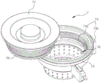
图5为本发明实施例中下水组件的整体示意图;Fig. 5 is the overall schematic diagram of the launching assembly in the embodiment of the present invention;
图6为图5另一角度的剖视图。FIG. 6 is a cross-sectional view from another angle of FIG. 5 .
具体实施方式Detailed ways
以下结合附图实施例对本发明作进一步详细描述。The present invention will be further described in detail below in conjunction with the accompanying drawings and embodiments.
如图1至图6所示,为本发明的一个优选实施例,在本实施例中,该渣水分离装置适用于清洗机中,这里所提到的清洗机包括箱体100、水槽2和研磨器3,箱体100内部中空形成清洗腔,水槽2与箱体100并排布置,本实施例中的渣水分离装置具体包括壳体1和推板4,其中壳体1的内部中空形成容腔10,容腔10具有出水口1b、用来与水槽2腔体相连通的进水口1a以及用来与下游研磨器3相连通的排出口1c,沿着流体的流动方向,出水口1b布置在进水口1a的下游,结合到清洗机中,即壳体1安装在水槽2的下方,研磨器3安装在排出口1c处。As shown in Figures 1 to 6, it is a preferred embodiment of the present invention. In this embodiment, the slag-water separation device is suitable for use in a cleaning machine. The cleaning machine mentioned here includes a
在本实施例中,对于沥水和残渣的收集,分成了两个独立的阶段,从结构上来看,上述的容腔10包括用来收集残渣的收集腔室12以及与收集腔室12并排布置的沥水腔室11,进水口1a和出水口1b均布置在沥水腔室11,出水口1b位于进水口1a的下方且与进水口1a贯通形成沥水流道,排出口1c布置在收集腔室12处。即这里的进水口1a位于排出口1c的斜上方并与排出口1c相互错位,这样的交错设计形式,可以将残渣的收集动作与排水动作分隔开来进行分别处理,能够更好地实现渣水分离,避免了直排时渣水混合的尴尬境地。In this embodiment, for the collection of drainage and residue, it is divided into two independent stages. From a structural point of view, the above-mentioned
本实施例中,推板4设于容腔10内且布置在进水口1a的下方,该推板4能靠近或者远离排出口1c,并在靠近所述排出口1c的状态下将残渣推送至排出口1c处,正是上述的沥水、排出结构,为推板4的推出动作提供了先决条件,从功能上讲,利用了推板4的间歇推动,能够在需要时驱动推板4进行残渣的集中处理,相比于传统的直排形式,垃圾处理方式更加灵活,残渣的储存不再受限于竖向的排出结构,无论是对残渣进行后续的烘干还是收集,都更加的方便。In this embodiment, the push plate 4 is arranged in the
具体而言,上述的沥水腔室11内还设置有第一渣篮5,第一渣篮5上间隔设置有多个沥水孔,推板4设于第一渣篮5内。当然,推板4的移动需要相应的动力源,在本实施例中,上述的壳体1上还设置有第一驱动器61,该第一驱动器61布置在容腔10的外围,且动力输出端与推板4驱动连接。且在壳体1上还设置有螺杆62,该螺杆62能转动地布置在沥水腔室11内且穿设在推板4上,进而驱动推板4移动,并且,螺杆62的延伸方向与沥水流道中流体流动方向相交叉。本实施例中的壳体1的侧部设置有安装座63,第一驱动器61设于安装座63的底部且输出轴向上延伸,螺杆62在对应端设置有第一传动齿64,第一驱动器61的输出轴上设置有第二传动齿65,螺杆62通过第一传动齿64和第二传动齿65的啮合传动,从而在第一驱动器61的驱动下绕自身轴线转动。螺杆62穿设在推板4的其中一侧,沥水腔室11内还设置有导向杆66,导向杆66与螺杆62同向延伸且穿设在推板4的另外一侧。Specifically, the above-mentioned
在推板4实现上述推出动作的同时,还能兼具挤压残渣实现主动排水的功能,为了配合推板4发力,本实施例中的沥水腔室11与收集腔室12通过中部的敞口相连通,收集腔室12中还设置有密封侧板13,该密封侧板13密封在敞口处,且能向远离敞口的方向移动,进而使渣水分离装置处于两种使用状态:While the push plate 4 realizes the above-mentioned push-out action, it can also have the function of extruding the residue to realize active drainage. The mouth is connected, and the
在沥水状态下,密封侧板13密封在敞口处,推板4移动至与密封侧板13相抵,推板4与密封侧板13之间形成用来挤压残渣余水的间隙;In the state of draining, the sealing
在收集状态下,密封侧板13移动至壳体1远离敞口的一侧,且沥水腔室11的底部与收集腔室12贯通形成供推板4将挤压后残渣推入排出口1c的通道。In the collection state, the sealing
实现密封的结构可以是不同形式,本实施例中的容腔10的内侧壁向内延伸有周向延伸的环形挡边14,在沥水状态下,密封侧板13抵靠在该环形挡边14上,且密封侧板13的周缘在与环形挡边14相对的位置上设置有环形密封圈15。这样环形挡边14与密封圈15的设计,不仅在密封侧板13与环形挡边14的侧壁处实现了面密封,还借助于环形密封圈15的作用,在面密封的基础上提升了密封效果,进而避免了水流的泄漏甚至是水滴的渗入。此外,密封侧板13的移动需要独立的驱动源,在收集腔室12内还设置有第二驱动器16,第二驱动器16的动力输出端与密封侧板13驱动连接,进而驱动密封侧板13移动。The structure for achieving sealing can be in different forms. In this embodiment, the inner side wall of the
为了确保水槽中的渣水混合物能进入到渣水分离装置中,该渣水分离装置还包括有下水组件7,下水组件7安装在进水口1a处,且至少局部位于洗碗机的水槽2内。本实施例中的下水组件7包括有自上而下依次布置的盖体71、下水座72和第二渣篮73,其中,下水座72的外缘具有用来与清洗机底壁安装的第一挡沿75,该下水座72顶部开口且内部中空形成内腔70,盖体71能拆卸地盖设在内腔70的开口处,第二渣篮73安装在下水座72的底部。此外,下水组件7还包括有锁止机构74,在盖体71盖设于内腔70开口处的状态下,锁止机构74的输出端作用在盖体71的侧壁上,以限制盖体71脱离开口。具体而言,锁止机构74包括锁止气缸741和锁止压杆742,锁止压杆742连接在锁止气缸741的输出端,且能在锁止气缸741的作用下沿着盖体71的径向移动,盖体71侧壁在底部向外凸出形成第二挡沿76,在盖体71盖设于内腔70开口处的状态下,锁止压杆742移动至第二挡沿76的上移路径上。本实施例中的锁止压杆742呈两端朝向同一侧弯曲的弧形结构,该弧形结构的内凹面与盖体71的外壁相匹配。In order to ensure that the slag-water mixture in the water tank can enter the slag-water separation device, the slag-water separation device also includes a
此外,对于盖体71的锁止和解锁,在下水座72的外围设置有独立的触发机构77,触发机构77中的触片78设置在下水座72的外围,且伸入至所述内腔70内,在盖体71盖设于下水座72的状态下,盖体71与触片78接触并接通触片78所对应的回路,进而给予锁止气缸741、第一驱动器61以及第二驱动器16不同的电信号,使得推板4和密封侧板13在不同的时间阶段实现不同的移动模式,从而实现渣水分离、挤压等不同的动作。由于电信号传递和控制部分不是本申请所要展现的重点,在此对于控制器以及实现各个控制部分的电元件不再做连接、结构和型号方面的赘述。推板4和密封侧板13在不同阶段的动作详见“工作过程”。In addition, for the locking and unlocking of the
工作过程:work process:
1、渣水分离:1. Slag water separation:
第二渣篮73可以根据需要选择性的安装在下水座72上,若第二渣篮73安装,则水从第二渣篮73和第一渣篮5的沥水孔中流走并被排出,残渣则留在第二渣篮73内,如果不需要进行深度的分离处理,则直接取出第二渣篮73,倒出残渣即可,如果需要分离处理,则在积累一定量的残渣之后,可以将第二渣篮73中的残渣倒入至下方的沥水腔室11中,并由第一渣篮5承接;若第二渣篮73未安装,则残渣和水直接流入到沥水腔室11中,此时大部分水直接从第一渣篮5的沥水孔中流走并被排出,而残渣则留在第一渣篮5内。这里第二渣篮73的设置目的是为用户提供更加多样灵活的残渣处理模式,且一旦有非厨余垃圾掉落,可以直接对第二渣篮73进行处理回收,避免对下游的研磨器3造成损伤。The
2、残渣转移2. Residue transfer
上述的阶段中,无论是否安装第二渣篮73,在不同的选项中,第一渣篮5都会有对残渣的收集,此时盖上盖体71,由于盖体71盖设时会接触到触发机构77中的触片78,上述的锁止机构74中的锁止气缸741驱动锁止压杆742抵靠在盖体71的侧壁上,并阻挡在第二挡沿76的上移路径上,此时无法从外界移开盖体71,整个下水组件就得到了相对密闭的内腔70空间,与此同时,推板4在第一驱动器61的驱动下向收集腔室12方向移动,同时将第一渣篮5内的残渣向密封在敞口处的密封侧板13上挤压,残渣受到挤压致使大部分水向两侧或底部从沥水孔流出,在保持挤压动作一定时长之后,密封侧板13在第二驱动器16的驱动下与推板4同向移动(朝向远离敞口方向),处理后的残渣最终被推送至排出口1c,并经由排出口1c进入到下游的研磨器3内,并进行研磨、烘干等进一步的工序。当然,推板4也可以采用不挤压残渣的方式将其直接推送,只需要密封侧板13在推板4到达相应位置之前进行避让即可,这里只示出最优的工序,对于第二种情况不再赘述。In the above-mentioned stage, no matter whether the
本发明所称的“流体连通”是指两个部件或部位(以下统一分别称为第一部位、第二部位)之间的空间位置关系,即流体(气体、液体或两者的混合)能从第一部位沿着流动路径流动或/和被运送到第二部位,可以是所述的第一部位、第二部位之间直接相连通,也可以是第一部位、第二部位之间通过至少一个第三者间接连通,该第三者可以是诸如管道、通道、导管、导流件、孔、槽等流体通道、也可以是允许流体流过的腔室或以上组合。The "fluid communication" referred to in the present invention refers to the spatial positional relationship between two parts or parts (hereinafter collectively referred to as the first part and the second part respectively), that is, the fluid (gas, liquid or a mixture of both) can Flow or/and be transported from the first position to the second position along the flow path, it may be that the first position and the second position are directly connected, or the first position and the second position may be passed through At least one third party communicates indirectly, and the third party may be a fluid channel such as a pipe, channel, conduit, flow guide, hole, groove, etc., or a chamber allowing fluid to flow through, or a combination of the above.
此外,在本发明的说明书及权利要求书中使用了表示方向的术语,诸如“前”、“后”、“上”、“下”、“左”、“右”、“侧”、“顶”、“底”等,用来描述本发明的各种示例结构部分和元件,但是在此使用这些术语只是为了方便说明的目的,是基于附图中显示的示例方位而确定的。由于本发明所公开的实施例可以按照不同的方向设置,所以这些表示方向的术语只是作为说明而不应视作为限制,比如“上”、“下”并不一定被限定为与重力方向相反或一致的方向。In addition, terms indicating directions, such as "front", "rear", "upper", "lower", "left", "right", "side", "top", are used in the description and claims of the present invention. ", "bottom", etc., are used to describe various exemplary structural parts and elements of the present invention, but these terms are used here for the purpose of convenience of description only, and are determined based on the exemplary orientations shown in the drawings. Since the disclosed embodiments of the present invention can be arranged in different directions, these terms indicating directions are for illustration only and should not be regarded as limitations. For example, "up" and "down" are not necessarily limited to the opposite direction or consistent direction.
Claims (18)
Priority Applications (1)
| Application Number | Priority Date | Filing Date | Title |
|---|---|---|---|
| CN202111461018.8A CN116196673B (en) | 2021-11-30 | 2021-11-30 | Slag-water separation device and cleaning machine |
Applications Claiming Priority (1)
| Application Number | Priority Date | Filing Date | Title |
|---|---|---|---|
| CN202111461018.8A CN116196673B (en) | 2021-11-30 | 2021-11-30 | Slag-water separation device and cleaning machine |
Publications (2)
| Publication Number | Publication Date |
|---|---|
| CN116196673A true CN116196673A (en) | 2023-06-02 |
| CN116196673B CN116196673B (en) | 2026-01-13 |
Family
ID=86511829
Family Applications (1)
| Application Number | Title | Priority Date | Filing Date |
|---|---|---|---|
| CN202111461018.8A Active CN116196673B (en) | 2021-11-30 | 2021-11-30 | Slag-water separation device and cleaning machine |
Country Status (1)
| Country | Link |
|---|---|
| CN (1) | CN116196673B (en) |
Cited By (1)
| Publication number | Priority date | Publication date | Assignee | Title |
|---|---|---|---|---|
| CN119791541A (en) * | 2025-01-07 | 2025-04-11 | 宁波方太厨具有限公司 | A cleaning machine |
Citations (5)
| Publication number | Priority date | Publication date | Assignee | Title |
|---|---|---|---|---|
| CN107060011A (en) * | 2017-06-02 | 2017-08-18 | 浙江机电职业技术学院 | A kind of dross extractor based on kitchen basin outlet device |
| CN209932650U (en) * | 2019-02-28 | 2020-01-14 | 宁波方太厨具有限公司 | Cleaning machine |
| JP2020179070A (en) * | 2019-04-24 | 2020-11-05 | 練韓奇 | Child dishwasher |
| CN113006218A (en) * | 2021-04-02 | 2021-06-22 | 宁波新冠联机电有限公司 | Kitchen waste disposer |
| CN217247177U (en) * | 2021-11-30 | 2022-08-23 | 宁波方太厨具有限公司 | Slag-water separation device and cleaning machine |
-
2021
- 2021-11-30 CN CN202111461018.8A patent/CN116196673B/en active Active
Patent Citations (5)
| Publication number | Priority date | Publication date | Assignee | Title |
|---|---|---|---|---|
| CN107060011A (en) * | 2017-06-02 | 2017-08-18 | 浙江机电职业技术学院 | A kind of dross extractor based on kitchen basin outlet device |
| CN209932650U (en) * | 2019-02-28 | 2020-01-14 | 宁波方太厨具有限公司 | Cleaning machine |
| JP2020179070A (en) * | 2019-04-24 | 2020-11-05 | 練韓奇 | Child dishwasher |
| CN113006218A (en) * | 2021-04-02 | 2021-06-22 | 宁波新冠联机电有限公司 | Kitchen waste disposer |
| CN217247177U (en) * | 2021-11-30 | 2022-08-23 | 宁波方太厨具有限公司 | Slag-water separation device and cleaning machine |
Cited By (1)
| Publication number | Priority date | Publication date | Assignee | Title |
|---|---|---|---|---|
| CN119791541A (en) * | 2025-01-07 | 2025-04-11 | 宁波方太厨具有限公司 | A cleaning machine |
Also Published As
| Publication number | Publication date |
|---|---|
| CN116196673B (en) | 2026-01-13 |
Similar Documents
| Publication | Publication Date | Title |
|---|---|---|
| CN106284556B (en) | A kind of intelligent garbage pulverization process system | |
| CN111134584A (en) | Sink dishwasher with residue disposal function and its intelligent linkage control system | |
| CN206174059U (en) | From washout type refuse treatment device | |
| CN202567904U (en) | Vegetable washing basin device for separating sources of kitchen wastes | |
| CN116196673A (en) | Slag-water separation device and cleaning machine | |
| CN217247177U (en) | Slag-water separation device and cleaning machine | |
| CN107165230A (en) | A multifunctional sink | |
| WO2021159591A1 (en) | Food garbage disposal and integrated-type kitchen electrical appliance | |
| CN214994370U (en) | A kitchen waste disposer | |
| CN220069645U (en) | Cleaning equipment base station and cleaning equipment | |
| CN213086951U (en) | Water tank garbage disposal device and intelligent kitchen equipment with garbage disposal function | |
| CN115262712A (en) | Garbage processor, control device and control method | |
| CN205399586U (en) | Automatically cleaning refuse treatment machine | |
| CN211228809U (en) | A new type of floor drain | |
| CN108252369A (en) | A kind of integrated water saving washstand | |
| CN108185944B (en) | Garbage dryer for sink dish washer | |
| CN208958048U (en) | A special food waste disposal device for dishwashers | |
| CN215330298U (en) | Can collect dirty closestool of processing excrement | |
| CN208388554U (en) | A kind of drying garbage device on water basin dish-washing machine | |
| CN112064736A (en) | Water tank garbage disposal device and intelligent kitchen equipment with garbage disposal function | |
| CN215053585U (en) | Water inlet overflow device and food waste treatment device with same | |
| CN118223575B (en) | Integrated discharge mechanism and integrated kitchen | |
| CN100497855C (en) | Table control touch type dewatering device | |
| CN224116805U (en) | Kitchen garbage solid-liquid separation device | |
| CN218437354U (en) | Household kitchen waste screening machine |
Legal Events
| Date | Code | Title | Description |
|---|---|---|---|
| PB01 | Publication | ||
| PB01 | Publication | ||
| SE01 | Entry into force of request for substantive examination | ||
| SE01 | Entry into force of request for substantive examination | ||
| GR01 | Patent grant | ||
| GR01 | Patent grant |