CN116201977A - Steel-plastic conversion tube with protective sleeve - Google Patents
Steel-plastic conversion tube with protective sleeve Download PDFInfo
- Publication number
- CN116201977A CN116201977A CN202310399177.2A CN202310399177A CN116201977A CN 116201977 A CN116201977 A CN 116201977A CN 202310399177 A CN202310399177 A CN 202310399177A CN 116201977 A CN116201977 A CN 116201977A
- Authority
- CN
- China
- Prior art keywords
- tube
- steel
- puncture rod
- sheath
- rod
- Prior art date
- Legal status (The legal status is an assumption and is not a legal conclusion. Google has not performed a legal analysis and makes no representation as to the accuracy of the status listed.)
- Granted
Links
Images




Classifications
-
- F—MECHANICAL ENGINEERING; LIGHTING; HEATING; WEAPONS; BLASTING
- F16—ENGINEERING ELEMENTS AND UNITS; GENERAL MEASURES FOR PRODUCING AND MAINTAINING EFFECTIVE FUNCTIONING OF MACHINES OR INSTALLATIONS; THERMAL INSULATION IN GENERAL
- F16L—PIPES; JOINTS OR FITTINGS FOR PIPES; SUPPORTS FOR PIPES, CABLES OR PROTECTIVE TUBING; MEANS FOR THERMAL INSULATION IN GENERAL
- F16L47/00—Connecting arrangements or other fittings specially adapted to be made of plastics or to be used with pipes made of plastics
- F16L47/18—Adjustable joints; Joints allowing movement
-
- F—MECHANICAL ENGINEERING; LIGHTING; HEATING; WEAPONS; BLASTING
- F16—ENGINEERING ELEMENTS AND UNITS; GENERAL MEASURES FOR PRODUCING AND MAINTAINING EFFECTIVE FUNCTIONING OF MACHINES OR INSTALLATIONS; THERMAL INSULATION IN GENERAL
- F16L—PIPES; JOINTS OR FITTINGS FOR PIPES; SUPPORTS FOR PIPES, CABLES OR PROTECTIVE TUBING; MEANS FOR THERMAL INSULATION IN GENERAL
- F16L47/00—Connecting arrangements or other fittings specially adapted to be made of plastics or to be used with pipes made of plastics
- F16L47/02—Welded joints; Adhesive joints
-
- F—MECHANICAL ENGINEERING; LIGHTING; HEATING; WEAPONS; BLASTING
- F16—ENGINEERING ELEMENTS AND UNITS; GENERAL MEASURES FOR PRODUCING AND MAINTAINING EFFECTIVE FUNCTIONING OF MACHINES OR INSTALLATIONS; THERMAL INSULATION IN GENERAL
- F16L—PIPES; JOINTS OR FITTINGS FOR PIPES; SUPPORTS FOR PIPES, CABLES OR PROTECTIVE TUBING; MEANS FOR THERMAL INSULATION IN GENERAL
- F16L47/00—Connecting arrangements or other fittings specially adapted to be made of plastics or to be used with pipes made of plastics
- F16L47/14—Flanged joints
-
- F—MECHANICAL ENGINEERING; LIGHTING; HEATING; WEAPONS; BLASTING
- F16—ENGINEERING ELEMENTS AND UNITS; GENERAL MEASURES FOR PRODUCING AND MAINTAINING EFFECTIVE FUNCTIONING OF MACHINES OR INSTALLATIONS; THERMAL INSULATION IN GENERAL
- F16L—PIPES; JOINTS OR FITTINGS FOR PIPES; SUPPORTS FOR PIPES, CABLES OR PROTECTIVE TUBING; MEANS FOR THERMAL INSULATION IN GENERAL
- F16L57/00—Protection of pipes or objects of similar shape against external or internal damage or wear
- F16L57/02—Protection of pipes or objects of similar shape against external or internal damage or wear against cracking or buckling
-
- Y—GENERAL TAGGING OF NEW TECHNOLOGICAL DEVELOPMENTS; GENERAL TAGGING OF CROSS-SECTIONAL TECHNOLOGIES SPANNING OVER SEVERAL SECTIONS OF THE IPC; TECHNICAL SUBJECTS COVERED BY FORMER USPC CROSS-REFERENCE ART COLLECTIONS [XRACs] AND DIGESTS
- Y02—TECHNOLOGIES OR APPLICATIONS FOR MITIGATION OR ADAPTATION AGAINST CLIMATE CHANGE
- Y02A—TECHNOLOGIES FOR ADAPTATION TO CLIMATE CHANGE
- Y02A20/00—Water conservation; Efficient water supply; Efficient water use
- Y02A20/20—Controlling water pollution; Waste water treatment
Landscapes
- Engineering & Computer Science (AREA)
- General Engineering & Computer Science (AREA)
- Mechanical Engineering (AREA)
- Rigid Pipes And Flexible Pipes (AREA)
Abstract
本发明公开了一种具有防护套的钢塑转换管,包括管体,管体的轴向两端均设置有第一环形件,管体端部的内侧以及第一环形件的内侧均设置有滑槽,管体的轴向两端分别设置有第一壳体和第二壳体,第一壳体上设置有安装孔。本发明中,第一囊体内设置了热固胶,第二囊体内设置了生石灰和活性炭,第三囊体内设置了水,依靠第二穿刺杆刺破第一囊体,使热固胶渗漏出来,第一穿刺杆刺破第三囊体,使水流出接触生石灰,生石灰遇水可以释放大量的热量,从而使热固胶可以受热固化,相较于卡扣连接,采用热固胶粘接更牢固,保证在长期使用后不易脱落,同时无需使用额外的加热设备,提高在狭小空间安装防护套的便捷性。

The invention discloses a steel-plastic conversion pipe with a protective sleeve, which comprises a pipe body, first ring parts are arranged at both ends of the pipe body in the axial direction, and the inner side of the end of the pipe body and the inner side of the first ring part are both provided with The chute, the axial ends of the pipe body are respectively provided with a first shell and a second shell, and the first shell is provided with a mounting hole. In the present invention, thermosetting glue is arranged in the first capsule, quicklime and activated carbon are arranged in the second capsule, water is arranged in the third capsule, and the first capsule is pierced by the second puncture rod to make the thermosetting glue leak When it comes out, the first puncture rod pierces the third capsule, so that the water flows out and contacts the quicklime. The quicklime can release a lot of heat when it meets water, so that the thermosetting adhesive can be cured by heat. Compared with the snap connection, the use of thermosetting adhesive bonding It is more firm, ensuring that it is not easy to fall off after long-term use, and does not need to use additional heating equipment, which improves the convenience of installing the protective cover in a small space.
Description
技术领域technical field
本发明涉及管道连接技术领域,尤其涉及一种具有防护套的钢塑转换管。The invention relates to the technical field of pipeline connection, in particular to a steel-plastic conversion pipe with a protective sleeve.
背景技术Background technique
目前,埋地和入户燃气管网中钢塑转换接头在钢塑转换处的PE端为应力集中的薄弱点,在运输、施工和使用过程中容易发生划伤或者剪切破坏,对管网运行安全造成一定的影响。At present, the PE end of the steel-plastic conversion joint at the steel-plastic conversion point in the buried and household gas pipeline network is a weak point of stress concentration, which is prone to scratches or shear damage during transportation, construction and use. certain impact on operational safety.
一般通用的方法是在钢塑转换薄弱处增加一段等径PE管材作为套管或者采用管径大小不同的宽窄段的护套管进行防护,其中护套管为轴向两半组成,靠设置的几个卡扣进行连接,由于卡扣多为塑料材质,并且体积较小,故在长期使用后其结构强度会下降,在埋地时因长期承受荷载或因受PE套管外部覆土压力与内部存在空隙导致内外压力不均衡,卡扣很容易变形失效或发生断裂,从而使钢塑转换接头失去防护效果。The general method is to add a section of equal-diameter PE pipe as a casing at the weak point of steel-plastic conversion, or use a wide and narrow section of sheath pipe with different diameters for protection. The sheath pipe is composed of two halves in the axial direction. Several buckles are connected. Since the buckles are mostly made of plastic and are small in size, their structural strength will decrease after long-term use. When buried in the ground, due to long-term load or due to the external soil pressure of the PE casing and the internal The existence of gaps leads to unbalanced internal and external pressure, and the buckle is easily deformed, failed or broken, so that the steel-plastic conversion joint loses its protective effect.
发明内容Contents of the invention
本发明的目的在于:为了解决上述问题,而提出的一种具有防护套的钢塑转换管。The object of the present invention is to propose a steel-plastic conversion pipe with a protective cover in order to solve the above problems.
为了实现上述目的,本发明采用了如下技术方案:In order to achieve the above object, the present invention adopts the following technical solutions:
一种具有防护套的钢塑转换管,包括管体,所述管体的轴向两端均设置有第一环形件,所述管体端部的内侧以及第一环形件的内侧均设置有滑槽,所述管体的轴向两端分别设置有第一壳体和第二壳体,所述第一壳体上设置有安装孔,所述管体的外周设置有两个半圆弧形的护套管片,所述护套管片的轴向两端均设置有半圆弧形的连接管片,护套管片的内侧设置有半圆弧形的第一凸起,两个所述护套管片之间设置有粘接部;所述粘接部包括两个第三壳体,两个所述第三壳体分别设置在两个所述护套管片上,其中一个所述第三壳体内设置有第一板体、第一囊体、弹性组件和第一穿刺杆,另一个所述第三壳体内设置有第二板体、第二囊体和第三囊体,所述第二板体上设置有第二穿刺杆,所述第一板体上设置有第一通孔,所述第二板体上设置有第二通孔,所述第一囊体的内部设置有热固胶,所述第二囊体的内部设置有生石灰和活性炭,所述第三囊体的内部设置有水。A steel-plastic conversion pipe with a protective sleeve, comprising a pipe body, first ring parts are provided at both axial ends of the pipe body, and the inside of the end of the pipe body and the inside of the first ring part are provided with A chute, the axial ends of the pipe body are respectively provided with a first shell and a second shell, the first shell is provided with a mounting hole, and the outer circumference of the pipe body is provided with two semicircular arcs The sheath segment, the axial ends of the sheath segment are provided with a semi-arc-shaped connecting segment, the inner side of the sheath segment is provided with a semi-arc-shaped first protrusion, and the two sheath segments Adhesive parts are arranged between the casing sheets; the adhesive parts include two third casings, and the two third casings are respectively arranged on the two jacket sheets, one of which is the third casing. A first plate, a first capsule, an elastic component and a first puncture rod are arranged in the housing, a second board, a second capsule and a third capsule are provided in the third housing, and the first The second plate is provided with a second puncture rod, the first plate is provided with a first through hole, the second plate is provided with a second through hole, the inside of the first capsule is provided with a thermal Solid glue, the interior of the second capsule is provided with quicklime and activated carbon, and the interior of the third capsule is provided with water.
优选地,所述管体的轴向两端的外周以及第一环形件靠近管体一端的外周均设置有环形凸起,两个所述环形凸起通过螺栓连接。Preferably, the outer circumferences of both ends of the tubular body in the axial direction and the outer circumference of the first ring member close to the end of the tubular body are provided with annular protrusions, and the two annular protrusions are connected by bolts.
优选地,所述第一壳体和第二壳体均为球形结构,所述安装孔设置有多个,所述管体和第一环形件内的两个所述滑槽上均设置有第一密封圈,所述第一壳体和第二壳体均与滑槽滑动接触,并且二者均与第一密封圈滑动接触。Preferably, both the first housing and the second housing are of spherical structure, the installation holes are provided in multiples, and the two slide grooves in the pipe body and the first ring are provided with the first A sealing ring, the first housing and the second housing are in sliding contact with the sliding groove, and both are in sliding contact with the first sealing ring.
优选地,所述第一凸起设置有多个,并且沿护套管片的轴向方向等间距设置,所述第一凸起的内侧与管体的外壁抵接。Preferably, the first protrusions are provided in multiples and arranged at equal intervals along the axial direction of the sheath segment, and the inner sides of the first protrusions abut against the outer wall of the tubular body.
优选地,所述连接管片靠近护套管片一端的外周设置有半圆弧形的第二凸起,所述第二凸起通过螺栓与环形凸起固定连接。Preferably, a semi-arc-shaped second protrusion is provided on the outer periphery of the connecting segment near one end of the sheath segment, and the second protrusion is fixedly connected to the annular protrusion through bolts.
优选地,所述连接管片远离护套管片一端的内侧设置有第二环形件,所述第二环形件的内侧设置有堵塞胶泥。Preferably, a second ring is provided on the inner side of the connecting segment away from the end of the sheath segment, and the inner side of the second ring is provided with plugging glue.
优选地,所述弹性组件包括筒体,所述筒体的内部设置有杆体,所述杆体的上端延伸至筒体的外部,并且延伸端设置有连接杆,所述杆体的下端与第一穿刺杆固定连接,所述第一穿刺杆位于筒体内,并且二者滑动连接,所述筒体的顶部与第一穿刺杆之间设置有弹性件。Preferably, the elastic assembly includes a cylinder, a rod is provided inside the cylinder, the upper end of the rod extends to the outside of the cylinder, and a connecting rod is provided at the extension end, the lower end of the rod is connected to the first puncture The rods are fixedly connected, the first puncture rod is located in the cylinder, and the two are slidably connected, and an elastic member is arranged between the top of the cylinder and the first puncture rod.
优选地,所述第一穿刺杆的底部以及第二穿刺杆的顶部均为锥形结构,所述第二穿刺杆上设置有多个固定环,所述第二囊体为无纺布材料,所述第一穿刺杆与第二通孔同轴设置,所述第二穿刺杆与第一通孔同轴设置,所述第二通孔内设置有第二密封圈。Preferably, the bottom of the first puncture rod and the top of the second puncture rod are conical structures, the second puncture rod is provided with a plurality of fixing rings, the second capsule is made of non-woven material, The first puncture rod is arranged coaxially with the second through hole, the second puncture rod is arranged coaxially with the first through hole, and a second sealing ring is arranged in the second through hole.
优选的,还包括热缩护套,该热缩护套将所述管体、套管片、连接管片、第一壳体以及第二壳体包裹,用以对本装置金属部分的防腐。Preferably, a heat-shrinkable sheath is also included, and the heat-shrinkable sheath wraps the tube body, the sleeve piece, the connection piece, the first shell and the second shell, so as to protect the metal part of the device from corrosion.
综上所述,由于采用了上述技术方案,本发明的有益效果是:In summary, owing to adopting above-mentioned technical scheme, the beneficial effect of the present invention is:
1、本申请通过设置护套管片,并且在护套管片上设置粘接部,粘接部设置了第一囊体、第二囊体、第三囊体、第一穿刺杆和第二穿刺杆,第一囊体内设置了热固胶,第二囊体内设置了生石灰和活性炭,第三囊体内设置了水,在安装防护套时,依靠第二穿刺杆刺破第一囊体,使热固胶渗漏出来,静置一段时间等所有的热固胶完全渗漏后,使第一穿刺杆刺破第三囊体,使水流出接触生石灰,生石灰遇水可以释放大量的热量,从而使热固胶可以受热固化,进而起到粘接护套管片的作用,相较于卡扣连接,采用热固胶粘接更牢固,保证在长期使用后不易脱落,同时以自热的方式加热热固胶,无需使用额外的加热设备,有助于提高在狭小空间安装防护套的便捷性。1. In this application, a sheath segment is provided, and an adhesive part is provided on the sheath segment, and the adhesive part is provided with a first capsule, a second capsule, a third capsule, a first puncture rod and a second puncture rod. Rod, thermosetting glue is set in the first capsule, quicklime and activated carbon are set in the second capsule, and water is set in the third capsule. When installing the protective cover, rely on the second puncture rod to puncture the first capsule to make the The solid glue leaks out, and after standing for a period of time until all the thermosetting glue leaks completely, the first puncture rod pierces the third capsule, so that the water flows out and contacts the quicklime, and the quicklime can release a large amount of heat when it meets water, so that the The thermosetting adhesive can be cured by heat, and then play the role of bonding the sheath segment. Compared with the snap connection, the thermosetting adhesive is more firmly bonded to ensure that it is not easy to fall off after long-term use, and it is heated by self-heating The heat-curing adhesive eliminates the need to use additional heating equipment, which helps to improve the ease of installing the protective cover in small spaces.
2、本申请通过设置管体,在管体两端分别设置第一壳体和第二壳体,第一壳体和第二壳体均与管体的端部滑动接触,因此在受到土壤沉降不同步时,第一壳体和第二壳体通过偏转,使PE管与钢管的连接部位仍具备良好的密封性和结构强度,从而提高转换管的使用可靠性。2. In this application, by setting the pipe body, the first shell and the second shell are respectively arranged at both ends of the pipe body. Both the first shell and the second shell are in sliding contact with the end of the pipe body. When not synchronous, the first housing and the second housing deflect, so that the joint between the PE pipe and the steel pipe still has good sealing and structural strength, thereby improving the reliability of the conversion pipe.
附图说明Description of drawings
图1示出了根据本发明实施例1提供的转换管和防护套整体结构示意图;Figure 1 shows a schematic diagram of the overall structure of a conversion tube and a protective sleeve provided according to
图2示出了根据本发明实施例1提供的转换管和防护套组合结构示意图;Fig. 2 shows a schematic diagram of the combined structure of a conversion tube and a protective sleeve provided according to
图3示出了根据本发明实施例1提供的转换管整体结构示意图;Fig. 3 shows a schematic diagram of the overall structure of the conversion tube provided according to
图4示出了根据本发明实施例1提供的转换管分解结构示意图;Fig. 4 shows a schematic diagram of an exploded structure of a conversion tube provided according to
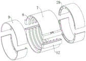
图5示出了根据本发明实施例1提供的防护套分解结构示意图;Fig. 5 shows a schematic diagram of an exploded structure of a protective sheath provided according to
图6示出了根据本发明实施例1提供的第三壳体、第一囊体、第二囊体和第三囊体结构示意图;Fig. 6 shows a schematic structural diagram of a third housing, a first capsule, a second capsule and a third capsule according to
图7示出了根据本发明实施例1提供的第三壳体、第一穿刺杆和第二穿刺杆结构示意图;Fig. 7 shows a schematic structural diagram of a third housing, a first puncture rod and a second puncture rod provided according to
图8示出了根据本发明实施例1提供的第一穿刺杆和弹性件结构示意图。Fig. 8 shows a schematic structural view of the first puncture rod and the elastic member according to
图9示出了根据本发明实施例2提供的整体结构示意图。FIG. 9 shows a schematic diagram of the overall structure provided according to
图例说明:illustration:
1、管体;2、第一环形件;3、滑槽;4、第一壳体;5、第二壳体;6、第一密封圈;7、护套管片;8、第一凸起;9、连接管片;10、第二环形件;11、堵塞胶泥;12、第三壳体;13、第一囊体;14、筒体;15、杆体;16、弹性件;17、第一穿刺杆;18、连接杆;19、第一通孔;20、第二囊体;21、第三囊体;22、第二穿刺杆;23、固定环;24、第二通孔;25、第二密封圈;26、安装孔;27、环形凸起;28、第二凸起;29、第一板体;30、第二板体;31热缩护套。1. Pipe body; 2. The first ring; 3. The chute; 4. The first shell; 5. The second shell; 6. The first sealing ring; 7. The sheath segment; 8. The
具体实施方式Detailed ways
下面将结合本发明实施例中的附图,对本发明实施例中的技术方案进行清楚、完整地描述,显然,所描述的实施例仅仅是本发明一部分实施例,而不是全部的实施例。基于本发明中的实施例,本领域普通技术人员在没有作出创造性劳动前提下所获得的所有其它实施例,都属于本发明保护的范围。The following will clearly and completely describe the technical solutions in the embodiments of the present invention with reference to the accompanying drawings in the embodiments of the present invention. Obviously, the described embodiments are only some, not all, embodiments of the present invention. Based on the embodiments of the present invention, all other embodiments obtained by persons of ordinary skill in the art without creative efforts fall within the protection scope of the present invention.
实施例1Example 1
请参阅图1-8,本发明提供一种技术方案:Referring to Figures 1-8, the present invention provides a technical solution:
一种具有防护套的钢塑转换管,包括管体1,管体1的轴向两端均设置有第一环形件2,管体1端部的内侧以及第一环形件2的内侧均设置有滑槽3,管体1的轴向两端分别设置有第一壳体4和第二壳体5,第一壳体4上设置有安装孔26,PE管插接在安装孔26中,钢管与第二壳体5通过法兰连接,在埋设的过程中需要保持管体1与PE管以及钢管均同轴,管体1的外周设置有两个半圆弧形的护套管片7,护套管片7的轴向两端均设置有半圆弧形的连接管片9,护套管片7的内侧设置有半圆弧形的第一凸起8,两个护套管片7之间设置有粘接部。粘接部用于连接两个护套管片7,护套管片7对PE管与钢管的连接部分起到支撑、防护作用。A steel-plastic conversion pipe with a protective sleeve, comprising a
具体的,如图1、图2、图3、图4和图5所示,第一壳体4和第二壳体5均为球形结构,安装孔26设置有多个,多个安装孔26的孔径不相同,两个安装孔26为一组,并且分布在第一壳体4的球径方向的两端,不同的安装孔26大小用于适配不同管径的PE管,PE管与安装孔26之间的缝隙设置密封垫,管体1和第一环形件2内的两个滑槽3上均设置有第一密封圈6,第一壳体4和第二壳体5均与滑槽3滑动接触,并且二者均与第一密封圈6滑动接触。第一密封圈6用于增强PE管与第一壳体4连接部分以及钢管与第二壳体5连接部分的气密性,在保证密封的同时,第一壳体4以及第二壳体5均与滑槽3滑动,在发生沉降不统一时,通过第一壳体4和第二壳体5的偏转,减少转换管结构承受的折弯压力,从而提高转换管的结构稳定性。第一凸起8设置有多个,并且沿护套管片7的轴向方向等间距设置,第一凸起8的内侧与管体1的外壁抵接。第一凸起8对管体1起到支撑作用,同时第一凸起8可以增加护套管片7的结构强度。管体1的轴向两端的外周以及第一环形件2靠近管体1一端的外周均设置有环形凸起27,两个环形凸起27通过螺栓连接。连接管片9靠近护套管片7一端的外周设置有半圆弧形的第二凸起28,第二凸起28通过螺栓与环形凸起27固定连接。管体1、第一环形件2和连接管片9三者通过螺栓连接为一体,拆装方便,结构稳定可靠。连接管片9远离护套管片7一端的内侧设置有第二环形件10,第二环形件10的内侧设置有堵塞胶泥11。连接管片9与第二环形件10为一体成型结构,堵塞胶泥11填充在第二环形件10与PE管以及钢管之间的缝隙内,用于提高转换管内部的密封性,减少腐蚀性物质进入转换管。Specifically, as shown in Fig. 1, Fig. 2, Fig. 3, Fig. 4 and Fig. 5, the
具体的,如图1、图5、图6、图7和图8所示,粘接部包括两个第三壳体12,两个第三壳体12分别设置在两个护套管片7上,第三壳体12固定连接在护套管片7的圆弧端部,其中一个第三壳体12内设置有第一板体29、第一囊体13、弹性组件和第一穿刺杆17,另一个第三壳体12内设置有第二板体30、第二囊体20和第三囊体21,第二板体30上设置有第二穿刺杆22,第一板体29上设置有第一通孔19,第二板体30上设置有第二通孔24,第一囊体13的内部设置有热固胶,第二囊体20的内部设置有生石灰和活性炭,第三囊体21的内部设置有水。弹性组件包括筒体14,筒体14的内部设置有杆体15,杆体15的上端延伸至筒体14的外部,并且延伸端设置有连接杆18,杆体15的下端与第一穿刺杆17固定连接,第一穿刺杆17位于筒体14内,并且二者滑动连接,筒体14的顶部与第一穿刺杆17之间设置有弹性件16。第一穿刺杆17的底部以及第二穿刺杆22的顶部均为锥形结构,第二穿刺杆22上设置有多个固定环23,第二囊体20为无纺布材料,第一穿刺杆17与第二通孔24同轴设置,第二穿刺杆22与第一通孔19同轴设置,第二通孔24内设置有第二密封圈25。在粘接时,两个第三壳体12对齐合并,第一穿刺杆17穿过第二通孔24,但其下端并未刺破第三囊体21,而第二穿刺杆22穿过第一通孔19将第一囊体13刺破,此时两个第三壳体12、第一板体29、第二板体30可以形成密闭空间,热固胶在重力作用下穿过第一通孔19进入密闭空间,待静置填满后,通过移动连接杆18使第一穿刺杆17往下移动刺破第三囊体21,即可使水流出,使生石灰与水反应释放热量,从而加热热固胶。热固胶在固化后,固定环23嵌在固化的热固胶内,起到锚定作用,提高两个护套管片7的连接强度。Specifically, as shown in Fig. 1, Fig. 5, Fig. 6, Fig. 7 and Fig. 8, the bonding part includes two
综上所述,本实施例所提供的一种具有防护套的钢塑转换管,PE管插接在安装孔26中,钢管与第二壳体5通过螺栓连接,护套管片7贴合管体1,两个护套管片7拼接完全覆盖管体1的外周,连接管片9通过螺栓与管体1固定连接,两个护套管片7拼接时,两个第三壳体12对齐合并,第二穿刺杆22上端穿过第一通孔19刺破第一囊体13,使热固胶穿过第一通孔19位于第一板体29与第二板体30之间,待静置五至十分钟后,热固胶将第一板体29与第二板体30之间的空间完全填满后,往下挤压连接杆18,使第一穿刺杆17的下端刺破第三囊体21,使水流出,第二囊体20中的生石灰遇水反应释放大量热量,从而加热热固胶使其固化,使两个护套管片7粘接为一体。To sum up, in this embodiment, a steel-plastic conversion pipe with a protective sleeve is provided. The PE pipe is inserted into the
实施例2Example 2
本实施例与实施例1大致相同,不同之处在于还包括热缩护套31,如图9所示,热缩护套31将管体、套管片、连接管片、第一壳体以及第二壳体包裹,其中PE管32端包裹距离为5cm~10cm,钢管33端包裹长度根据施工确定。This embodiment is substantially the same as
实施例的上述说明,使本领域专业技术人员能够实现或使用本发明。对这些实施例的多种修改对本领域的专业技术人员来说将是显而易见的,本文中所定义的一般原理可以在不脱离本发明的精神或范围的情况下,在其它实施例中实现。因此,本发明将不会被限制于本文所示的这些实施例,而是要符合与本文所公开的原理和新颖特点相一致的最宽的范围。The above description of the embodiments enables those skilled in the art to implement or use the present invention. Various modifications to these embodiments will be readily apparent to those skilled in the art, and the general principles defined herein may be implemented in other embodiments without departing from the spirit or scope of the invention. Therefore, the present invention will not be limited to the embodiments shown herein, but is to be accorded the widest scope consistent with the principles and novel features disclosed herein.
Claims (9)
Priority Applications (1)
| Application Number | Priority Date | Filing Date | Title |
|---|---|---|---|
| CN202310399177.2A CN116201977B (en) | 2023-04-14 | 2023-04-14 | A steel-plastic transition pipe with a protective sleeve |
Applications Claiming Priority (1)
| Application Number | Priority Date | Filing Date | Title |
|---|---|---|---|
| CN202310399177.2A CN116201977B (en) | 2023-04-14 | 2023-04-14 | A steel-plastic transition pipe with a protective sleeve |
Publications (2)
| Publication Number | Publication Date |
|---|---|
| CN116201977A true CN116201977A (en) | 2023-06-02 |
| CN116201977B CN116201977B (en) | 2026-03-24 |
Family
ID=86509645
Family Applications (1)
| Application Number | Title | Priority Date | Filing Date |
|---|---|---|---|
| CN202310399177.2A Active CN116201977B (en) | 2023-04-14 | 2023-04-14 | A steel-plastic transition pipe with a protective sleeve |
Country Status (1)
| Country | Link |
|---|---|
| CN (1) | CN116201977B (en) |
Cited By (1)
| Publication number | Priority date | Publication date | Assignee | Title |
|---|---|---|---|---|
| CN118320626A (en) * | 2024-06-11 | 2024-07-12 | 无锡维邦工业设备成套技术有限公司 | CIP cleaning equipment, hollow fiber nanofiltration water purification system and water purification process |
Citations (14)
| Publication number | Priority date | Publication date | Assignee | Title |
|---|---|---|---|---|
| DE4332529A1 (en) * | 1993-09-24 | 1995-03-30 | Karl Heinz Vahlbrauk | Pipeline |
| KR20110095608A (en) * | 2010-02-19 | 2011-08-25 | 김욱군 | Band type sewage and sewage pipe connection mechanism |
| US20120027648A1 (en) * | 2010-07-27 | 2012-02-02 | General Electric Company | Interfacing caps for microfluidic devices and methods of making and using the same |
| CN204025989U (en) * | 2014-09-10 | 2014-12-17 | 齐刚 | Universal joint for pipeline |
| CN105257933A (en) * | 2015-11-06 | 2016-01-20 | 重庆互通管道技术设备有限公司 | Seal hoop |
| CN108612938A (en) * | 2018-06-21 | 2018-10-02 | 江苏腾驰科技有限公司 | A kind of double-sealing device for automobile engine mesohigh pipeline |
| CN210890481U (en) * | 2019-10-30 | 2020-06-30 | 苏州众程节燃能源科技有限公司 | Fossil fuel pollution-reducing energy-saving device |
| CN112393051A (en) * | 2020-11-16 | 2021-02-23 | 天长市云联管道有限公司 | Connecting and sealing mechanism for steel plastic pipe and plastic pipe |
| CN113446743A (en) * | 2021-06-30 | 2021-09-28 | 北京市地质工程勘察院 | Open type heat exchange inner tube of geothermal well |
| CN216280073U (en) * | 2021-11-24 | 2022-04-12 | 四川德源管道科技股份有限公司 | Epoxy steel sleeve for repairing assembled pipeline |
| CN114382985A (en) * | 2020-10-21 | 2022-04-22 | 李兴文 | High leakproofness pipe fitting based on intelligence selfreparing |
| CN216851267U (en) * | 2021-12-14 | 2022-06-28 | 大连联合高分子材料有限公司 | Wire copper joint protection architecture |
| CN217130685U (en) * | 2022-03-04 | 2022-08-05 | 广东联塑科技实业有限公司 | Crossover sub is moulded to anti ground settlement PE gas steel |
| CN217328916U (en) * | 2022-01-27 | 2022-08-30 | 中铁二院北方勘察设计有限责任公司 | Building water supply and drainage pipeline connecting device |
-
2023
- 2023-04-14 CN CN202310399177.2A patent/CN116201977B/en active Active
Patent Citations (14)
| Publication number | Priority date | Publication date | Assignee | Title |
|---|---|---|---|---|
| DE4332529A1 (en) * | 1993-09-24 | 1995-03-30 | Karl Heinz Vahlbrauk | Pipeline |
| KR20110095608A (en) * | 2010-02-19 | 2011-08-25 | 김욱군 | Band type sewage and sewage pipe connection mechanism |
| US20120027648A1 (en) * | 2010-07-27 | 2012-02-02 | General Electric Company | Interfacing caps for microfluidic devices and methods of making and using the same |
| CN204025989U (en) * | 2014-09-10 | 2014-12-17 | 齐刚 | Universal joint for pipeline |
| CN105257933A (en) * | 2015-11-06 | 2016-01-20 | 重庆互通管道技术设备有限公司 | Seal hoop |
| CN108612938A (en) * | 2018-06-21 | 2018-10-02 | 江苏腾驰科技有限公司 | A kind of double-sealing device for automobile engine mesohigh pipeline |
| CN210890481U (en) * | 2019-10-30 | 2020-06-30 | 苏州众程节燃能源科技有限公司 | Fossil fuel pollution-reducing energy-saving device |
| CN114382985A (en) * | 2020-10-21 | 2022-04-22 | 李兴文 | High leakproofness pipe fitting based on intelligence selfreparing |
| CN112393051A (en) * | 2020-11-16 | 2021-02-23 | 天长市云联管道有限公司 | Connecting and sealing mechanism for steel plastic pipe and plastic pipe |
| CN113446743A (en) * | 2021-06-30 | 2021-09-28 | 北京市地质工程勘察院 | Open type heat exchange inner tube of geothermal well |
| CN216280073U (en) * | 2021-11-24 | 2022-04-12 | 四川德源管道科技股份有限公司 | Epoxy steel sleeve for repairing assembled pipeline |
| CN216851267U (en) * | 2021-12-14 | 2022-06-28 | 大连联合高分子材料有限公司 | Wire copper joint protection architecture |
| CN217328916U (en) * | 2022-01-27 | 2022-08-30 | 中铁二院北方勘察设计有限责任公司 | Building water supply and drainage pipeline connecting device |
| CN217130685U (en) * | 2022-03-04 | 2022-08-05 | 广东联塑科技实业有限公司 | Crossover sub is moulded to anti ground settlement PE gas steel |
Non-Patent Citations (1)
| Title |
|---|
| 赵劲松, 谢世雄: "一种新的钢塑复合管制造技术", 聚氯乙烯, no. 06, 30 November 2004 (2004-11-30), pages 29 - 34 * |
Cited By (2)
| Publication number | Priority date | Publication date | Assignee | Title |
|---|---|---|---|---|
| CN118320626A (en) * | 2024-06-11 | 2024-07-12 | 无锡维邦工业设备成套技术有限公司 | CIP cleaning equipment, hollow fiber nanofiltration water purification system and water purification process |
| CN118320626B (en) * | 2024-06-11 | 2024-10-11 | 无锡维邦工业设备成套技术有限公司 | CIP cleaning equipment, hollow fiber nanofiltration water purification system and water purification process |
Also Published As
| Publication number | Publication date |
|---|---|
| CN116201977B (en) | 2026-03-24 |
Similar Documents
| Publication | Publication Date | Title |
|---|---|---|
| US4398754A (en) | Electrically insulated pipe coupling and method for making the same | |
| JP2015517067A (en) | Polymer fitting assembly | |
| CN116201977A (en) | Steel-plastic conversion tube with protective sleeve | |
| KR20110075645A (en) | A support unit for connecting a double heat pipe and a double heat pipe connector having the same, and a method of connecting a double heat pipe using the same | |
| KR20050026630A (en) | Joint equipment for steel reinforcing | |
| CN109357098A (en) | Insert seal pipe fitting and its installation method | |
| KR101024577B1 (en) | Synthetic resin pipe connecting device | |
| CN204611125U (en) | A kind of metallic hose | |
| KR101400290B1 (en) | Heat shrinkable sleeve for coupling pipes | |
| KR200393028Y1 (en) | Apparatus for connecting pipe | |
| KR101588213B1 (en) | Method for connecting large diameter pipes | |
| KR20090095693A (en) | Saddle for Branching a Plastic Pipe and Branching Method Using the Same | |
| RU2162183C1 (en) | Method of pipe connection for transportation of corrosive liquids | |
| CN205136927U (en) | Pipe sealing joint who connects bamboo -shaped prestressing force plastics pipe racks blast pipe | |
| CN215908576U (en) | Composite pipe connecting assembly and water supply and drainage pipeline | |
| KR20120127862A (en) | Expansion joint and method for manufacturing the same | |
| CN211118213U (en) | Plastic composite pipe joint | |
| CN213655930U (en) | Polyethylene HDPE steel band reinforcing helical bellows with connector | |
| KR102372761B1 (en) | Pipe connection part used for various purposes, and pipe connection method using the same | |
| CN209213281U (en) | Insert seal pipe fitting | |
| RU2147097C1 (en) | Method of connection of pipe lines transporting aggressive fluids | |
| RU2321792C2 (en) | Fitting for pipelines made of polyethylene reinforced pipes | |
| RU2586031C2 (en) | Joint of reinforced polymer tube | |
| CN223228098U (en) | Sealing joint | |
| CN115711332B (en) | A connection structure and connection method for steel wire mesh-wound polyethylene composite pipe |
Legal Events
| Date | Code | Title | Description |
|---|---|---|---|
| PB01 | Publication | ||
| PB01 | Publication | ||
| SE01 | Entry into force of request for substantive examination | ||
| SE01 | Entry into force of request for substantive examination | ||
| GR01 | Patent grant | ||
| GR01 | Patent grant |