CN116352425A - Automatic press riveting device and press riveting method for sheet metal machining - Google Patents
Automatic press riveting device and press riveting method for sheet metal machining Download PDFInfo
- Publication number
- CN116352425A CN116352425A CN202310170799.8A CN202310170799A CN116352425A CN 116352425 A CN116352425 A CN 116352425A CN 202310170799 A CN202310170799 A CN 202310170799A CN 116352425 A CN116352425 A CN 116352425A
- Authority
- CN
- China
- Prior art keywords
- workpiece
- riveting
- splint
- support platform
- workbench
- Prior art date
- Legal status (The legal status is an assumption and is not a legal conclusion. Google has not performed a legal analysis and makes no representation as to the accuracy of the status listed.)
- Granted
Links
Images


Classifications
-
- B—PERFORMING OPERATIONS; TRANSPORTING
- B23—MACHINE TOOLS; METAL-WORKING NOT OTHERWISE PROVIDED FOR
- B23P—METAL-WORKING NOT OTHERWISE PROVIDED FOR; COMBINED OPERATIONS; UNIVERSAL MACHINE TOOLS
- B23P19/00—Machines for simply fitting together or separating metal parts or objects, or metal and non-metal parts, whether or not involving some deformation; Tools or devices therefor so far as not provided for in other classes
- B23P19/04—Machines for simply fitting together or separating metal parts or objects, or metal and non-metal parts, whether or not involving some deformation; Tools or devices therefor so far as not provided for in other classes for assembling or disassembling parts
- B23P19/06—Screw or nut setting or loosening machines
- B23P19/062—Pierce nut setting machines
-
- Y—GENERAL TAGGING OF NEW TECHNOLOGICAL DEVELOPMENTS; GENERAL TAGGING OF CROSS-SECTIONAL TECHNOLOGIES SPANNING OVER SEVERAL SECTIONS OF THE IPC; TECHNICAL SUBJECTS COVERED BY FORMER USPC CROSS-REFERENCE ART COLLECTIONS [XRACs] AND DIGESTS
- Y02—TECHNOLOGIES OR APPLICATIONS FOR MITIGATION OR ADAPTATION AGAINST CLIMATE CHANGE
- Y02P—CLIMATE CHANGE MITIGATION TECHNOLOGIES IN THE PRODUCTION OR PROCESSING OF GOODS
- Y02P70/00—Climate change mitigation technologies in the production process for final industrial or consumer products
- Y02P70/10—Greenhouse gas [GHG] capture, material saving, heat recovery or other energy efficient measures, e.g. motor control, characterised by manufacturing processes, e.g. for rolling metal or metal working
Landscapes
- Engineering & Computer Science (AREA)
- Mechanical Engineering (AREA)
- Press Drives And Press Lines (AREA)
Abstract
本发明涉及钣金压铆加工技术领域,尤其涉及一种钣金加工用的自动压铆装置,包括工作台、冲压机、控制器、自动送料器和压铆模具,所述冲压机安装在工作台的上表面后侧,所述控制器安装在工作台的上表面右后角,且控制器与冲压机电性连接,所述自动送料器安装在工作台的上表面,且自动送料器位于冲压机正下方,所述自动送料器与控制器电性连接,所述压铆模具安装在自动送料器的顶部前侧。本发明具备工件定位功能,利于工作人员将工件压铆孔对准压铆模具,既能缓解工作人员视疲劳,又不会造成工作人员手臂酸痛,工件水平压铆的压铆质量得以保证,还具备压铆螺母顶出功能,工件重新压铆省时省力,提升合格率,节省成本。

The invention relates to the technical field of sheet metal riveting processing, in particular to an automatic riveting device for sheet metal processing, including a workbench, a punching machine, a controller, an automatic feeder and a riveting die, and the punching machine is installed on a working On the rear side of the upper surface of the table, the controller is installed on the right rear corner of the upper surface of the workbench, and the controller is electrically connected to the stamping machine, the automatic feeder is installed on the upper surface of the workbench, and the automatic feeder is located at the Right below the machine, the automatic feeder is electrically connected to the controller, and the riveting mold is installed on the top front side of the automatic feeder. The invention has the function of workpiece positioning, which is beneficial for the staff to align the pressure riveting hole of the workpiece with the pressure riveting mold, which can not only relieve the visual fatigue of the staff, but also not cause soreness in the arms of the staff, the quality of the pressure riveting of the horizontal pressure riveting of the workpiece can be guaranteed, and the Equipped with the ejection function of the riveting nut, the re-riveting of the workpiece saves time and labor, improves the pass rate and saves costs.
Description
技术领域technical field
本发明涉及钣金压铆加工技术领域,尤其涉及一种钣金加工用的自动压铆装置以及压铆方法。The invention relates to the technical field of sheet metal riveting processing, in particular to an automatic riveting device and a riveting method for sheet metal processing.
背景技术Background technique
自动冲压机是利用冲压机设备和专用连接模具通过一个瞬间强高压加工过程,依据板件本身材料的冷挤压变形,形成一个具有一定抗拉和抗剪强度的无应力集中内部镶嵌圆点,即可将不同材质不同厚度的两层或多层板件连接起来;The automatic stamping machine is to use the stamping machine equipment and the special connecting mold to go through an instantaneous high-pressure processing process, according to the cold extrusion deformation of the plate itself, to form a stress-free internal mosaic dot with a certain tensile and shear strength. Two or more layers of boards of different materials and different thicknesses can be connected;
自动冲压机主要包括冲压机、控制器、自动送料器压铆模具和脚踏开关,使用时,工作人员将工件压铆孔插在压铆模具上,自动送料器将压铆螺母送至压铆模具正上方,冲压机下压压铆螺母,将压铆螺母嵌在工件压铆孔内,达到工件压铆加工;The automatic punching machine mainly includes a punching machine, a controller, an automatic feeder, a riveting die and a foot switch. When in use, the staff inserts the riveting hole of the workpiece into the riveting die, and the automatic feeder sends the riveting nut to the riveting die. Right above the die, press the riveting nut under the punching machine, and embed the riveting nut in the riveting hole of the workpiece to achieve the riveting process of the workpiece;
由于工件上压铆孔较小,每次压铆作业前,工作人员都要仔细观察压铆模具和工件压铆孔,使压铆孔对准压铆模具,工作人员还要手臂悬空把持工件,长此以往工作,既会造成视疲劳,又容易导致手臂酸痛,工件压铆时难以保持水平状态,压铆质量无法保证,受压铆螺母质量差、或者操作不当都会引起工件压铆不合格,然而现有的冲压机是不具备压铆螺母顶出功能的,重新压铆费时费力,直接报废又浪费成本,因此,有必要提出一种具备定位功能的自动压铆装置。Because the riveting hole on the workpiece is small, before each riveting operation, the staff must carefully observe the riveting mold and the riveting hole of the workpiece, so that the riveting hole is aligned with the riveting mold, and the staff also have to hold the workpiece with their arms suspended. If things go on like this, it will not only cause visual fatigue, but also easily lead to sore arms. It is difficult to maintain a horizontal state when the workpiece is riveted, and the quality of the riveting cannot be guaranteed. Some punching machines do not have the function of riveting nut ejection. Re-riveting takes time and effort, and it is directly scrapped and wastes cost. Therefore, it is necessary to propose an automatic riveting device with positioning function.
发明内容Contents of the invention
本发明为了克服现有技术中工作人员放置工件过程劳动强度大,准确度低,以及不具备压铆螺母顶出功能的缺点,本发明要解决的技术问题是一种钣金加工用的自动压铆装置以及压铆方法。In order to overcome the disadvantages of high labor intensity, low accuracy, and lack of push-out function of rivet nuts in the process of placing workpieces by workers in the prior art, the technical problem to be solved by the present invention is an automatic rivet nut for sheet metal processing. A riveting device and a riveting method.
为实现上述目的,本发明提供如下技术方案:一种钣金加工用的自动压铆装置,包括工作台、冲压机、控制器、自动送料器和压铆模具,所述冲压机安装在工作台的上表面后侧,所述控制器安装在工作台的上表面右后角,且控制器与冲压机电性连接,所述自动送料器安装在工作台的上表面,且自动送料器位于冲压机正下方,所述自动送料器与控制器电性连接,所述压铆模具安装在自动送料器的顶部前侧,还包括:支撑平台,支撑平台安装在所述工作台的上表面右前角,且支撑平台上表面与压铆模具上表面位于同一水平面;定位器数量为若干个,呈两排从左至右安装在所述支撑平台的上表面;修复机构,安装在所述工作台的左侧壁;In order to achieve the above object, the present invention provides the following technical solutions: an automatic riveting device for sheet metal processing, including a workbench, a punching machine, a controller, an automatic feeder and a riveting die, and the punching machine is installed on the workbench The rear side of the upper surface of the workbench, the controller is installed on the right rear corner of the upper surface of the workbench, and the controller is electrically connected to the stamping machine, the automatic feeder is installed on the upper surface of the workbench, and the automatic feeder is located on the punching machine Directly below, the automatic feeder is electrically connected to the controller, and the riveting mold is installed on the top front side of the automatic feeder, and also includes: a support platform, which is installed on the right front corner of the upper surface of the workbench, And the upper surface of the support platform is located on the same level as the upper surface of the riveting mold; the number of locators is several, and they are installed on the upper surface of the support platform in two rows from left to right; the repair mechanism is installed on the left side of the workbench side wall;
目的在于实现调整挡板的位置和角度,对工件起到定位作用,所述定位器包括:导轨内嵌在所述支撑平台的顶部,且导轨内腔呈燕尾形;滑块能够前后滑动的插接在所述导轨的内腔;挡板通过销轴能够旋转的安装在所述滑块的顶部;压杆通过销轴能够旋转的安装在所述挡板的前侧左端;支撑杆安装在所述挡板的前侧右端;把手套接在所述支撑杆的外壁,且把手左侧设置有滑道,所述压杆贯穿滑道内腔;U型架安装在所述压杆的前端;吸盘数量为两个,分别安装在所述U型架的两端,且吸盘吸附在支撑平台上表面对挡板定位。The purpose is to realize the adjustment of the position and angle of the baffle, and to position the workpiece. The locator includes: a guide rail embedded in the top of the support platform, and the inner cavity of the guide rail is dovetail-shaped; connected to the inner cavity of the guide rail; the baffle is rotatably mounted on the top of the slider through a pin; the pressure rod is rotatably mounted on the front left end of the baffle through a pin; the support rod is mounted on the The front right end of the baffle plate; the handle is connected to the outer wall of the support rod, and the left side of the handle is provided with a slideway, and the pressure rod runs through the inner cavity of the slideway; the U-shaped frame is installed on the front end of the pressure rod; the suction cup There are two in number, which are respectively installed at both ends of the U-shaped frame, and the suction cups are adsorbed on the upper surface of the support platform to position against the baffle.
优选的,前后相对的两个所述定位器上的挡板相对面顶部为斜面。Preferably, the tops of the opposite surfaces of the baffles on the two front and rear opposite locators are sloped.
优选的,所述支撑平台、导轨和滑块的上表面均在同一水平面上。Preferably, the upper surfaces of the support platform, the guide rail and the slider are all on the same level.
优选的,实现顶针的上移,目的在于顶出工件中部合格的压铆螺母,所述修复机构包括:第一夹板,第一夹板固定连接在所述工作台的左侧壁前端,所述第一夹板的上表面中部开设有第一插孔;基座安装在所述第一夹板的下表面,且基座与第一插孔位置相对应;顶出液压油缸安装在所述基座的底端中心位置;顶针安装在所述顶出液压油缸的输出端;旋转组件安装在所述第一夹板的后侧中心位置;第二夹板安装在所述旋转组件的顶端,且第二夹板的上表面中部开设有第二插孔。Preferably, the upward movement of the ejector pin is aimed at ejecting the qualified rivet nut in the middle of the workpiece. The repair mechanism includes: a first splint fixedly connected to the front end of the left side wall of the workbench, and the first splint A first socket is opened in the middle of the upper surface of a splint; the base is installed on the lower surface of the first splint, and the base corresponds to the position of the first socket; the ejection hydraulic cylinder is installed on the bottom of the base end center position; the thimble is installed at the output end of the ejection hydraulic cylinder; the rotating assembly is installed at the rear center of the first clamping plate; the second clamping plate is installed at the top of the rotating assembly, and on the second clamping plate A second jack is opened in the middle of the surface.
优选的,所述第二夹板回转至第一夹板正上方时,第二插孔与第一插孔位置位于同一垂直线上。Preferably, when the second splint is rotated to directly above the first splint, the positions of the second insertion hole and the first insertion hole are located on the same vertical line.
优选的,目的在于第二夹板旋转后固定的作用,所述旋转组件包括:底座,底座固定连接在所述第一夹板的后侧中心位置,且底座的内腔底部沿周向等距开设有卡槽;转轴通过轴承能够旋转的安装在所述底座的内腔底端中心位置;套筒安装在所述转轴的顶端,且套筒的内壁沿上下方向开设有齿槽,所述套筒的外壁与第二夹板前侧固定连接;弹簧和齿轮从上至下插接在所述套筒的内腔,且齿轮外壁与齿槽相插接;凸块数量为两个,位置左右相对的固定连接在所述齿轮的底端,在所述弹簧的作用下齿轮上的凸块插入卡槽内腔。Preferably, the purpose is to fix the second splint after rotation, the rotating assembly includes: a base, the base is fixedly connected to the center position of the rear side of the first splint, and the bottom of the inner cavity of the base is equidistant along the circumferential direction. card slot; the rotating shaft is rotatably installed at the center of the bottom end of the inner cavity of the base through a bearing; the sleeve is installed at the top of the rotating shaft, and the inner wall of the sleeve is provided with tooth grooves along the up and down direction. The outer wall is fixedly connected to the front side of the second splint; the spring and the gear are inserted into the inner cavity of the sleeve from top to bottom, and the outer wall of the gear is inserted into the tooth groove; the number of protrusions is two, and the positions are fixed relative to each other It is connected to the bottom end of the gear, and under the action of the spring, the protrusion on the gear is inserted into the inner cavity of the slot.
优选的,所述凸块的形状呈弧形。Preferably, the bump is arc-shaped.
上述装置的压铆方法,包括以下步骤:The pressure riveting method of the above-mentioned device comprises the following steps:
步骤一,工件定位调试,上提把手,以支撑杆为旋转中心,促使把手上提U型架,吸盘脱离支撑平台,解除对挡板的定位,先将工件放在支撑平台上,并且工件压铆孔插在压铆模具上,通过滑块使挡板移动,并根据工件外形使挡板顺势转动,利用支撑平台上不同位置的挡板对工件夹持,下压把手,压杆带动U型架下压吸盘,吸盘吸附在支撑平台上,对挡板定位,完成工件定位调试,通过挡板的限位作用,可使工件下放到支撑平台上时,工件压铆孔刚好处在压铆模具上,操作简单;Step 1, workpiece positioning and debugging, lift the handle, take the support rod as the rotation center, push the handle to lift the U-shaped frame, the suction cup is separated from the support platform, release the positioning of the baffle, first put the workpiece on the support platform, and press the workpiece Insert the riveting hole into the riveting mold, move the baffle through the slider, and make the baffle rotate according to the shape of the workpiece, use the baffles at different positions on the support platform to clamp the workpiece, press down the handle, and the pressure bar drives the U-shaped Press the suction cup under the frame, the suction cup is adsorbed on the support platform, position the baffle, and complete the positioning and debugging of the workpiece. Through the limit function of the baffle, when the workpiece is lowered to the support platform, the riveting hole of the workpiece is just right on the riveting mold on, easy to operate;
步骤二,通过控制器驱使冲压机动作,冲头下移冲压压铆螺母,将压铆螺母嵌入工件压铆孔中,实现工件压铆加工;Step 2: Drive the punching machine to move through the controller, move the punch down to punch the rivet nut, insert the rivet nut into the rivet hole of the workpiece, and realize the rivet processing of the workpiece;
步骤三,工件上压铆螺母取出前定位,工件放在第一夹板上表面,移动工件并使压铆螺母处在第一插孔正上方;
步骤四,转动第二夹板,促使套筒和转轴同步转动,在齿槽对齿轮限位作用下,套筒扭力牵引齿轮转动,由于凸块呈弧形,凸块能够自由脱离卡槽,直至第二夹板覆盖在工件上表面,弹簧为齿轮提供一个向下的弹力,促使凸块插入相对应位置的卡槽中,套筒得到固定,进而使第二夹板固定;Step 4: Turn the second splint to make the sleeve and the rotating shaft rotate synchronously. Under the limit action of the tooth groove on the gear, the torque of the sleeve pulls the gear to rotate. Since the protrusion is arc-shaped, the protrusion can freely break away from the slot until the second The second splint covers the upper surface of the workpiece, and the spring provides a downward elastic force for the gear, prompting the protrusion to be inserted into the slot at the corresponding position, the sleeve is fixed, and then the second splint is fixed;
步骤五,通过顶出液压油缸推动顶针上移,顶针将压铆螺母从工件上顶出,达到压铆螺母拆卸的目的,以便重新加工工件。
与现有技术相比,本发明具有如下有益效果:Compared with the prior art, the present invention has the following beneficial effects:
1、本发明通过上下移动把手,可使压杆进行上下摆动,以便实现吸盘吸附在支撑平台上,在滑块的辅助下,挡板得到移动并旋转后固定,从而利用多个挡板对工件限位,具备工件定位功能,利于工作人员将工件压铆孔对准压铆模具,既能缓解工作人员视疲劳,又不会造成工作人员手臂酸痛,工件水平压铆的压铆质量得以保证;1. In the present invention, by moving the handle up and down, the pressure rod can be swung up and down, so as to realize the adsorption of the suction cup on the support platform. With the assistance of the slider, the baffle is moved and fixed after being rotated, so that multiple baffles are used to fix the workpiece. Limit position, with the workpiece positioning function, which is beneficial for the staff to align the riveting hole of the workpiece with the riveting mold, which can not only relieve the visual fatigue of the staff, but also not cause sore arms of the staff, and the quality of the riveting of the horizontal riveting of the workpiece can be guaranteed;
2、本发明通过弹簧弹力为齿轮提供一个向下的弹力,可使套筒旋转后凸块插入相对应位置的卡槽中,对旋转后的第二夹板起到固定作用,以便于第一夹板和第二夹板配合对工件限位,通过顶出液压油缸驱使顶针上移,顶针顶出工件上的压铆螺母,具备压铆螺母顶出功能,工件重新压铆省时省力,提升合格率,节省成本。2. The present invention provides a downward elastic force for the gear through the elastic force of the spring, so that the protrusion can be inserted into the slot at the corresponding position after the sleeve is rotated, so as to fix the second splint after rotation, so that the first splint can Cooperate with the second splint to limit the position of the workpiece, drive the thimble up through the ejector hydraulic cylinder, and the thimble ejects the rivet nut on the workpiece, with the function of rivet nut ejection, the re-riveting of the workpiece saves time and effort, and improves the pass rate. cut costs.
附图说明Description of drawings
图1为本发明结构示意图;Fig. 1 is a structural representation of the present invention;
图2为本发明定位器结构示意图;Fig. 2 is a structural schematic diagram of the locator of the present invention;
图3为本发明定位器左视剖面图;Fig. 3 is a left view sectional view of the positioner of the present invention;
图4为本发明修复机构结构示意图;Fig. 4 is a structural schematic diagram of the repair mechanism of the present invention;
图5为本发明修复机构主视剖面图;Figure 5 is a front sectional view of the repair mechanism of the present invention;
图6为本发明旋转组件主视剖面图;Fig. 6 is a front sectional view of the rotating assembly of the present invention;
图7为本发明齿轮仰视图。Fig. 7 is a bottom view of the gear of the present invention.
图中:1-工作台,2-冲压机,3-控制器,4-自动送料器,5-压铆模具,6-支撑平台,7-定位器,8-修复机构,71-导轨,72-滑块,73-挡板,74-压杆,75-支撑杆,76-把手,77-U型架,78-吸盘,81-第一夹板,82-第一插孔,83-基座,84-顶出液压油缸,85-顶针,86-旋转组件,87-第二夹板,88-第二插孔,861-底座,862-卡槽,863-转轴,864-套筒,865-齿槽,866-弹簧,867-齿轮,868-凸块。In the figure: 1-Workbench, 2-Punching machine, 3-Controller, 4-Automatic feeder, 5-Riveting die, 6-Support platform, 7-Positioner, 8-Repair mechanism, 71-Guide rail, 72 -slider, 73-baffle plate, 74-pressure rod, 75-support rod, 76-handle, 77-U-shaped frame, 78-suction cup, 81-first splint, 82-first jack, 83-base , 84-Ejection hydraulic cylinder, 85-Ejector pin, 86-Rotary assembly, 87-Second splint, 88-Second socket, 861-Base, 862-Slot, 863-Rotating shaft, 864-Sleeve, 865- Tooth groove, 866-spring, 867-gear, 868-projection.
实施方式Implementation
下面将结合本发明实施例中的附图,对本发明实施例中的技术方案进行清楚、完整地描述,显然,所描述的实施例仅仅是本发明一部分实施例,而不是全部的实施例。基于本发明中的实施例,本领域普通技术人员在没有做出创造性劳动前提下所获得的所有其他实施例,都属于本发明保护的范围。The following will clearly and completely describe the technical solutions in the embodiments of the present invention with reference to the accompanying drawings in the embodiments of the present invention. Obviously, the described embodiments are only some, not all, embodiments of the present invention. Based on the embodiments of the present invention, all other embodiments obtained by persons of ordinary skill in the art without making creative efforts belong to the protection scope of the present invention.
本发明提供一种技术方案:一种钣金加工用的自动压铆装置,如图1-3所示,包括工作台1、冲压机2、控制器3、自动送料器4和压铆模具5,冲压机2安装在工作台1的上表面后侧,控制器3安装在工作台1的上表面右后角,且控制器3与冲压机2电性连接,自动送料器4安装在工作台1的上表面,且自动送料器4位于冲压机2正下方,自动送料器4与控制器3电性连接,压铆模具5安装在自动送料器4的顶部前侧,还包括支撑平台6、定位器7和修复机构8,支撑平台6安装在工作台1的上表面右前角,且支撑平台6上表面与压铆模具5上表面位于同一水平面;定位器7数量为若干个,呈两排从左至右安装在支撑平台6的上表面;修复机构8安装在工作台1的左侧壁;The present invention provides a technical solution: an automatic riveting device for sheet metal processing, as shown in Figure 1-3, including a workbench 1, a
通过控制器3驱使冲压机2动作,冲头下移冲压压铆螺母,将压铆螺母嵌入工件压铆孔中,实现工件压铆加工;The
如图2和3所示,定位器7包括导轨71、滑块72、挡板73、压杆74、支撑杆75、把手76、U型架77和吸盘78,导轨71内嵌在支撑平台6的顶部,且导轨71内腔呈燕尾形,防止滑块72脱离导轨71;滑块72能够前后滑动的插接在导轨71的内腔,通过滑块72在导轨71内滑动实现挡板73的运动;挡板73通过销轴能够旋转的安装在滑块72的顶部,挡板73对工件起到限位作用,前后相对的两个定位器7上的挡板73相对面顶部为斜面,挡板73围成的空间从上至下从大到小,便于工作人员将工件精准放在支撑平台6上;压杆74通过销轴能够旋转的安装在挡板73的前侧左端,对U型架77起到支撑作用;支撑杆75安装在挡板73的前侧右端;把手76套接在支撑杆75的外壁,且把手76左侧设置有滑道,滑道与压杆74活动连接,可使压杆74上下摆动时能够牵引压杆74,压杆74贯穿滑道内腔;U型架77安装在压杆74的前端;吸盘78数量为两个,分别安装在U型架77的两端,且吸盘78吸附在支撑平台6上表面对挡板73定位;As shown in Figures 2 and 3, the
工件定位调试,上提把手76,以支撑杆75为旋转中心,促使把手76上提U型架77,吸盘78脱离支撑平台6,解除对挡板73的定位,先将工件放在支撑平台6上,并且工件压铆孔插在压铆模具5上,通过滑块72使挡板73移动,并根据工件外形使挡板73顺势转动,利用支撑平台6上不同位置的挡板73对工件夹持,下压把手76,压杆74带动U型架77下压吸盘78,吸盘78吸附在支撑平台6上,对挡板73定位,完成工件定位调试,通过挡板73的限位作用,可使工件下放到支撑平台6上时,工件压铆孔刚好处在压铆模具5上,操作简单。Workpiece positioning debugging, lifting the
作为优选方案,更进一步的,支撑平台6、导轨71和滑块72的上表面均在同一水平面上,当工件放在支撑平台6上,保证工件不会出现翘板。As a preferred solution, further, the upper surfaces of the
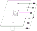
作为优选方案,更进一步的,如图4和5所示,修复机构8包括第一夹板81、第一插孔82、基座83、顶出液压油缸84、顶针85、旋转组件86、第二夹板87和第二插孔88,第一夹板81固定连接在工作台1的左侧壁前端,用于工件的摆放,第一夹板81的上表面中部开设有第一插孔82;基座83安装在第一夹板81的下表面,且基座83与第一插孔82位置相对应;顶出液压油缸84安装在基座83的底端中心位置;顶针85安装在顶出液压油缸84的输出端;旋转组件86安装在第一夹板81的后侧中心位置;第二夹板87安装在旋转组件86的顶端,利用第一夹板81和第二夹板87的配合对工件夹持,且第二夹板87的上表面中部开设有第二插孔88,第二夹板87回转至第一夹板81正上方时,第二插孔88与第一插孔82位置位于同一垂直线上,通过第一插孔82和第二插孔88为顶针85预留出移动空间,顶针85外径小于工件的压铆孔,防止顶针85工作时损坏工件。As a preferred solution, further, as shown in Figures 4 and 5, the
作为优选方案,更进一步的,如图6和7所示,旋转组件86包括底座861、卡槽862、转轴863、套筒864、齿槽865、弹簧866、齿轮867和凸块868,底座861固定连接在第一夹板81的后侧中心位置,且底座861的内腔底部沿周向等距开设有卡槽862,底座861与第一夹板81合为一体,进而使卡槽862与凸块868配合能够对套筒864定位;转轴863通过轴承能够旋转的安装在底座861的内腔底端中心位置;套筒864安装在转轴863的顶端,且套筒864的内壁沿上下方向开设有齿槽865,齿槽865起到齿轮867限位作用,使齿轮867能够上下移动的同时,还能跟随套筒864转动,套筒864的外壁与第二夹板87前侧固定连接;弹簧866和齿轮867从上至下插接在套筒864的内腔,且齿轮867外壁与齿槽865相插接,弹簧866为齿轮867提供一个向下的弹力,确保凸块868能够稳定停留在卡槽862中;凸块868数量为两个,位置左右相对的固定连接在齿轮867的底端,在弹簧866的作用下齿轮867上的凸块868插入卡槽862内腔;凸块868的形状呈弧形,当套筒864转动时,齿轮867跟随套筒864转动,在卡槽862的抵挡下凸块868受压上移,从而使凸块868能够自由进出卡槽862;As a preferred solution, further, as shown in Figures 6 and 7, the rotating
工件上压铆螺母取出前定位,工件放在第一夹板81上表面,移动工件并使压铆螺母处在第一插孔82正上方;Position the rivet nut on the workpiece before taking it out, place the workpiece on the upper surface of the
转动第二夹板87,促使套筒864和转轴863同步转动,在齿槽865对齿轮867限位作用下,套筒864扭力牵引齿轮867转动,由于凸块868呈弧形,凸块868能够自由脱离卡槽862,直至第二夹板87覆盖在工件上表面,弹簧866为齿轮867提供一个向下的弹力,促使凸块868插入相对应位置的卡槽862中,套筒864得到固定,进而使第二夹板87固定;Rotate the
通过顶出液压油缸84推动顶针85上移,顶针85将压铆螺母从工件上顶出,达到压铆螺母拆卸的目的,以便重新加工工件。The
尽管已经示出和描述了本发明的实施例,对于本领域的普通技术人员而言,可以理解在不脱离本发明的原理和精神的情况下可以对这些实施例进行多种变化、修改、替换和变型,本发明的范围由所附权利要求及其等同物限定。Although the embodiments of the present invention have been shown and described, those skilled in the art can understand that various changes, modifications and substitutions can be made to these embodiments without departing from the principle and spirit of the present invention. and modifications, the scope of the invention is defined by the appended claims and their equivalents.
Claims (8)
Priority Applications (1)
| Application Number | Priority Date | Filing Date | Title |
|---|---|---|---|
| CN202310170799.8A CN116352425B (en) | 2023-02-27 | 2023-02-27 | Automatic press riveting device and press riveting method for sheet metal machining |
Applications Claiming Priority (1)
| Application Number | Priority Date | Filing Date | Title |
|---|---|---|---|
| CN202310170799.8A CN116352425B (en) | 2023-02-27 | 2023-02-27 | Automatic press riveting device and press riveting method for sheet metal machining |
Publications (2)
| Publication Number | Publication Date |
|---|---|
| CN116352425A true CN116352425A (en) | 2023-06-30 |
| CN116352425B CN116352425B (en) | 2025-05-23 |
Family
ID=86911420
Family Applications (1)
| Application Number | Title | Priority Date | Filing Date |
|---|---|---|---|
| CN202310170799.8A Active CN116352425B (en) | 2023-02-27 | 2023-02-27 | Automatic press riveting device and press riveting method for sheet metal machining |
Country Status (1)
| Country | Link |
|---|---|
| CN (1) | CN116352425B (en) |
Citations (5)
| Publication number | Priority date | Publication date | Assignee | Title |
|---|---|---|---|---|
| US5177849A (en) * | 1990-07-02 | 1993-01-12 | Muskegon Automation Equipment, Inc. | Brake shoe rivet press |
| DE102017209118A1 (en) * | 2017-05-31 | 2018-12-06 | Robert Bosch Gmbh | PUNCHING DEVICE FOR PUTTING A PUNCH WITH A VIBRATOR SUPPORTING A STAMPING POWER, AND METHOD FOR PUNCHING WITH SUCH A PUNCHING RIVET DEVICE |
| CN216501983U (en) * | 2021-11-10 | 2022-05-13 | 湖南泰川科技有限公司 | Quick positioning device for sheet metal riveting press |
| CN216858133U (en) * | 2021-12-29 | 2022-07-01 | 四川凯拓电器有限公司 | Novel sheet metal working squeeze riveter |
| CN216881560U (en) * | 2022-02-15 | 2022-07-05 | 安徽博世精密机械有限公司 | Numerical control squeeze riveter for sheet metal processing |
-
2023
- 2023-02-27 CN CN202310170799.8A patent/CN116352425B/en active Active
Patent Citations (5)
| Publication number | Priority date | Publication date | Assignee | Title |
|---|---|---|---|---|
| US5177849A (en) * | 1990-07-02 | 1993-01-12 | Muskegon Automation Equipment, Inc. | Brake shoe rivet press |
| DE102017209118A1 (en) * | 2017-05-31 | 2018-12-06 | Robert Bosch Gmbh | PUNCHING DEVICE FOR PUTTING A PUNCH WITH A VIBRATOR SUPPORTING A STAMPING POWER, AND METHOD FOR PUNCHING WITH SUCH A PUNCHING RIVET DEVICE |
| CN216501983U (en) * | 2021-11-10 | 2022-05-13 | 湖南泰川科技有限公司 | Quick positioning device for sheet metal riveting press |
| CN216858133U (en) * | 2021-12-29 | 2022-07-01 | 四川凯拓电器有限公司 | Novel sheet metal working squeeze riveter |
| CN216881560U (en) * | 2022-02-15 | 2022-07-05 | 安徽博世精密机械有限公司 | Numerical control squeeze riveter for sheet metal processing |
Also Published As
| Publication number | Publication date |
|---|---|
| CN116352425B (en) | 2025-05-23 |
Similar Documents
| Publication | Publication Date | Title |
|---|---|---|
| CN101293263A (en) | Multi-station automatic stretching processing method and punch device using same | |
| CN115283567B (en) | A blank stamping, clamping and flipping device for producing hexagonal nuts | |
| CN113319157A (en) | Intelligent automatic stamping die | |
| CN202155423U (en) | Battery metal shell manufacturing equipment | |
| CN116352425A (en) | Automatic press riveting device and press riveting method for sheet metal machining | |
| CN111992698B (en) | Clamp for casting | |
| TW201016345A (en) | Automatic riveting machine for fastening pin of weight clutch | |
| CN214349195U (en) | Punching machine ejection mechanism | |
| CN217393492U (en) | A stamping die for LED lamp power supply cover | |
| CN114472783A (en) | Aluminum alloy forging and pressing die | |
| CN221362141U (en) | Automatic processing equipment for metal stamping parts | |
| CN119057496B (en) | Cutting device and method based on embroidery presser foot production | |
| CN209174646U (en) | Pressing and bending device and metal tube double end bending machine | |
| CN114029392B (en) | Motorcycle parts stamping equipment | |
| JP4289484B2 (en) | Die mounting device in punch press | |
| CN223718240U (en) | Automatic riveting equipment | |
| CN224042415U (en) | In-mold self-riveting stamping die | |
| CN113020376A (en) | Stamping device and control method thereof | |
| CN223339243U (en) | Adjustable clamping device for machining | |
| CN112264546A (en) | Punching machine ejection mechanism | |
| CN217531975U (en) | Auto-parts press that machining precision is high | |
| CN214294008U (en) | Single bimodulus integrated configuration hand mould seat is with hand mould mounting tool under line | |
| CN217990827U (en) | Forging and pressing forming device | |
| CN223718930U (en) | Chamfering equipment part positioning and fixing tool | |
| CN221336316U (en) | Processing equipment for punching aluminum plate |
Legal Events
| Date | Code | Title | Description |
|---|---|---|---|
| PB01 | Publication | ||
| PB01 | Publication | ||
| SE01 | Entry into force of request for substantive examination | ||
| SE01 | Entry into force of request for substantive examination | ||
| GR01 | Patent grant | ||
| GR01 | Patent grant |