CN116360077A - Large-view-field short-focus projection lens and LCD projector - Google Patents
Large-view-field short-focus projection lens and LCD projector Download PDFInfo
- Publication number
- CN116360077A CN116360077A CN202310199203.7A CN202310199203A CN116360077A CN 116360077 A CN116360077 A CN 116360077A CN 202310199203 A CN202310199203 A CN 202310199203A CN 116360077 A CN116360077 A CN 116360077A
- Authority
- CN
- China
- Prior art keywords
- lens
- optical axis
- axis direction
- light
- along
- Prior art date
- Legal status (The legal status is an assumption and is not a legal conclusion. Google has not performed a legal analysis and makes no representation as to the accuracy of the status listed.)
- Granted
Links
- 230000003287 optical effect Effects 0.000 claims abstract description 60
- 230000005540 biological transmission Effects 0.000 claims abstract description 4
- 230000009471 action Effects 0.000 abstract description 3
- 230000000007 visual effect Effects 0.000 abstract description 2
- 238000010586 diagram Methods 0.000 description 3
- 230000004075 alteration Effects 0.000 description 2
- 230000009286 beneficial effect Effects 0.000 description 2
- 238000003384 imaging method Methods 0.000 description 2
- 238000004891 communication Methods 0.000 description 1
- 230000007547 defect Effects 0.000 description 1
- 230000000694 effects Effects 0.000 description 1
- 230000002349 favourable effect Effects 0.000 description 1
- 239000003292 glue Substances 0.000 description 1
- 238000012986 modification Methods 0.000 description 1
- 230000004048 modification Effects 0.000 description 1
Images
Classifications
-
- G—PHYSICS
- G02—OPTICS
- G02B—OPTICAL ELEMENTS, SYSTEMS OR APPARATUS
- G02B13/00—Optical objectives specially designed for the purposes specified below
- G02B13/001—Miniaturised objectives for electronic devices, e.g. portable telephones, webcams, PDAs, small digital cameras
- G02B13/0015—Miniaturised objectives for electronic devices, e.g. portable telephones, webcams, PDAs, small digital cameras characterised by the lens design
- G02B13/002—Miniaturised objectives for electronic devices, e.g. portable telephones, webcams, PDAs, small digital cameras characterised by the lens design having at least one aspherical surface
- G02B13/0045—Miniaturised objectives for electronic devices, e.g. portable telephones, webcams, PDAs, small digital cameras characterised by the lens design having at least one aspherical surface having five or more lenses
-
- G—PHYSICS
- G02—OPTICS
- G02B—OPTICAL ELEMENTS, SYSTEMS OR APPARATUS
- G02B13/00—Optical objectives specially designed for the purposes specified below
- G02B13/06—Panoramic objectives; So-called "sky lenses" including panoramic objectives having reflecting surfaces
-
- G—PHYSICS
- G03—PHOTOGRAPHY; CINEMATOGRAPHY; ANALOGOUS TECHNIQUES USING WAVES OTHER THAN OPTICAL WAVES; ELECTROGRAPHY; HOLOGRAPHY
- G03B—APPARATUS OR ARRANGEMENTS FOR TAKING PHOTOGRAPHS OR FOR PROJECTING OR VIEWING THEM; APPARATUS OR ARRANGEMENTS EMPLOYING ANALOGOUS TECHNIQUES USING WAVES OTHER THAN OPTICAL WAVES; ACCESSORIES THEREFOR
- G03B21/00—Projectors or projection-type viewers; Accessories therefor
- G03B21/005—Projectors using an electronic spatial light modulator but not peculiar thereto
- G03B21/006—Projectors using an electronic spatial light modulator but not peculiar thereto using LCD's
-
- G—PHYSICS
- G03—PHOTOGRAPHY; CINEMATOGRAPHY; ANALOGOUS TECHNIQUES USING WAVES OTHER THAN OPTICAL WAVES; ELECTROGRAPHY; HOLOGRAPHY
- G03B—APPARATUS OR ARRANGEMENTS FOR TAKING PHOTOGRAPHS OR FOR PROJECTING OR VIEWING THEM; APPARATUS OR ARRANGEMENTS EMPLOYING ANALOGOUS TECHNIQUES USING WAVES OTHER THAN OPTICAL WAVES; ACCESSORIES THEREFOR
- G03B21/00—Projectors or projection-type viewers; Accessories therefor
- G03B21/14—Details
- G03B21/142—Adjusting of projection optics
Landscapes
- Physics & Mathematics (AREA)
- General Physics & Mathematics (AREA)
- Optics & Photonics (AREA)
- Lenses (AREA)
Abstract
The application provides a projection lens and LCD projector of short burnt of big visual field, projection lens includes: the first lens, the second lens, the third lens, the fourth lens and the fifth lens are sequentially arranged along the light transmission direction; wherein the first lens, the second lens and the fifth lens all have positive focal power, and the third lens and the fourth lens all have negative focal power; the light incident surface of the first lens along the optical axis direction is a convex surface, and the light emergent surface of the first lens along the optical axis direction is a concave surface; the light incident surface and the light emergent surface of the second lens along the optical axis direction are convex; the light incident surface and the light emergent surface of the third lens along the optical axis direction are concave surfaces; the light incident surface and the light emergent surface of the fourth lens along the optical axis direction are concave surfaces; the light incident surface and the light emergent surface of the fifth lens along the optical axis direction are convex. The projection lens of the application ensures that the projection lens can ensure a larger field angle and a short focal length, and simultaneously can reduce the number of lenses used by the projection lens under the combined action of five lenses, so that the whole projection lens is small in size and light in weight.
Description
Technical Field
The present disclosure relates to the field of LCD projection technology, and in particular, to a large-field-of-view short-focus projection lens and an LCD projector.
Background
The projection lens determines the optical parameters of the projector, and some defects are common in the projection lens on the market at present. For example, the focal length is too large, so that the projection ratio of the projector is too large, for example, a 5.7 inch LCD projector lens on the market has the focal length of about 190mm and the projection ratio of about 1.5; for example, the field of view of the lens is generally in the range of 40-45 degrees, so that the LCD cannot be imaged off-axis, and the consumption experience of a user is seriously affected in certain specific scenes.
Disclosure of Invention
The present application is directed to a large-field-of-view short-focus projection lens and an LCD projector, which solve the drawbacks and disadvantages of the prior art.
The application discloses a projection lens of short burnt of large visual field includes: the first lens, the second lens, the third lens, the fourth lens and the fifth lens are sequentially arranged along the light transmission direction; wherein the first lens, the second lens and the fifth lens all have positive focal power, and the third lens and the fourth lens all have negative focal power;
the light incident surface of the first lens along the optical axis direction is a convex surface, and the light emergent surface of the first lens along the optical axis direction is a concave surface;
the light incident surface and the light emergent surface of the second lens along the optical axis direction are convex;
the light incident surface and the light emergent surface of the third lens along the optical axis direction are concave surfaces;
the light incident surface and the light emergent surface of the fourth lens along the optical axis direction are concave surfaces;
the light incident surface and the light emergent surface of the fifth lens along the optical axis direction are convex.
Compared with the prior art, the projection lens provided by the embodiment of the application ensures a larger field angle and a short focal length, and reduces the number of lenses used by the projection lens under the combined action of the five lenses, so that the whole projection lens is small in size and light in weight.
In a preferred or alternative embodiment, the light incident surface and the light emergent surface of the third lens are aspheric.
In a preferred or alternative embodiment, the projection lens satisfies the following relationship:
2.0≤f1/f≤3.0;
1.0≤f2/f≤2.0;
-1.5≤f3/f≤-0.5;
-1.0≤f4/f≤-0.5;
0.2≤f5/f≤0.7;
the f is a focal length of the projection lens, the f1 is a focal length of the first lens, the f2 is a focal length of the second lens, the f3 is a focal length of the third lens, the f4 is a focal length of the fourth lens, and the f5 is a focal length of the fifth lens.
In a preferred or alternative embodiment, the projection lens satisfies the following relationship:
1.0≤f1/f2≤2.0;
-2.5≤f1/f3≤-1.5;
-2.0≤f4/f5≤-1.0;
wherein f1 is a focal length of the first lens, f2 is a focal length of the second lens, f3 is a focal length of the third lens, f4 is a focal length of the fourth lens, and f5 is a focal length of the fifth lens.
In a preferred or alternative embodiment, the projection lens satisfies the following relationship:
1.70≥Nd1≥1.60;1.70≥Nd2≥1.60;1.65≥Nd3≥1.58;1.65≥Nd4≥1.60;1.75≥Nd5≥1.70;
wherein Nd1 is a refractive index of the first lens, nd2 is a refractive index of the second lens, nd3 is a refractive index of the third lens, nd4 is a refractive index of the fourth lens, and Nd5 is a refractive index of the fifth lens.
In a preferred or alternative embodiment, the projection lens satisfies the following relationship:
0.5≤T1/T2≤1.5;
0.5≤T3/T4≤2.0;
T3≥2.5mm;
T5≥10mm;
TTL≤65mm;
the TTL is the total length of the projection lens, T1 is the thickness of the lens of the first lens along the optical axis direction, T2 is the thickness of the lens of the second lens along the optical axis direction, T3 is the thickness of the lens of the third lens along the optical axis direction, T4 is the thickness of the lens of the fourth lens along the optical axis direction, and T5 is the thickness of the lens of the fifth lens along the optical axis direction.
In a preferred or alternative embodiment, the projection lens satisfies the following relationship:
6mm≤D12≤9mm,9mm≤D23≤12mm,5mm≤D34≤8mm;
wherein D12 is a distance between the light exit surface of the first lens and the light entrance surface of the second lens in the optical axis direction, D23 is a distance between the light exit surface of the second lens and the light entrance surface of the third lens in the optical axis direction, and D34 is a distance between the light exit surface of the third lens and the light entrance surface of the fourth lens in the optical axis direction.
In a preferred or alternative embodiment, the light exit surface of the fourth lens and the light entrance surface of the fifth lens are attached to each other.
The application relates to an LCD projector, comprising: a large field of view short focus projection lens as described above.
For a better understanding and implementation, the present application is described in detail below with reference to the drawings.
Drawings
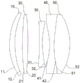
Fig. 1 is a schematic structural diagram of a projection lens according to an embodiment of the present application;
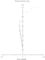
fig. 2 is a distortion chart corresponding to a projection lens according to an embodiment of the present application;
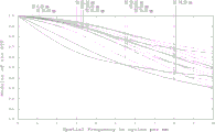
FIG. 3 is a graph of a modulation transfer function corresponding to a projection lens according to an embodiment of the present application;
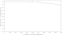
fig. 4 is a relative illuminance diagram corresponding to the projection lens in the embodiment of the present application.
Detailed Description
The following description of the embodiments of the present application will be made clearly and fully with reference to the accompanying drawings, in which it is evident that the embodiments described are only some, but not all, of the embodiments of the present application. All other embodiments, which can be made by one of ordinary skill in the art without undue burden from the present disclosure, are within the scope of the present disclosure.
It should be understood that in the description of the present application, the terms "center," "upper," "lower," "front," "rear," "left," "right," "vertical," "horizontal," "top," "bottom," "inner," "outer," and the like indicate orientations or positional relationships based on the orientations or positional relationships illustrated in the drawings, merely to facilitate description of the present application and simplify the description, and do not indicate or imply that the device or element being referred to must have a specific orientation, be configured and operated in a specific orientation, and therefore should not be construed as limiting the present application. The terms "first," "second," and the like are used for descriptive purposes only and are not to be construed as indicating or implying a relative importance or implicitly indicating the number of technical features indicated, i.e., features defining "first," "second," may explicitly or implicitly include one or more such features. Furthermore, unless otherwise indicated, the meaning of "a plurality" is two or more.
It should be noted that, in the description of the present application, unless explicitly specified and limited otherwise, the terms "disposed," "connected," and "hollow" are to be construed broadly, and may be, for example, fixedly connected, detachably connected, or integrally connected; can be mechanically or electrically connected; can be directly connected or indirectly connected through an intermediate medium, and can be communication between two elements. The specific meaning of the terms in this application will be understood by those of ordinary skill in the art in a specific context.
Referring to fig. 1, an embodiment of the present application provides a large-field short-focal projection lens, including: the first lens 10, the second lens 20, the third lens 30, the fourth lens 40, and the fifth lens 50 are sequentially disposed in the light transmission direction. The projection lens according to the present embodiment may be applied to an LCD projector, and light emitted from an LCD screen of the LCD projector is emitted through the first lens 10, the second lens 20, the third lens 30, the fourth lens 40 and the fifth lens 50, so as to form a projection image.
Wherein the first lens 10, the second lens 20 and the fifth lens 50 each have positive optical power, and the third lens 30 and the fourth lens 40 each have negative optical power, the optical power being used to represent the ability of the projection lens to deflect light, wherein a lens having positive optical power is used to represent the ability of the lens to converge light, and a lens having negative optical power is used to represent the ability of the lens to diverge light.
In the embodiment of the present application, the light incident surface 11 of the first lens 10 along the optical axis direction is a convex surface, and the light emergent surface 12 along the optical axis direction is a concave surface; the light incident surface 21 and the light emergent surface 22 of the second lens 20 along the optical axis direction are both convex; the light incident surface 31 and the light emergent surface 32 of the third lens 30 along the optical axis direction are both concave surfaces; the light incident surface 41 and the light emergent surface 42 of the fourth lens 40 along the optical axis direction are both concave surfaces; the light incident surface 51 and the light emergent surface 52 of the fifth lens 50 along the optical axis direction are both convex.
The projection lens provided by the embodiment of the application ensures a larger field angle and a short focal length, and reduces the number of lenses used by the projection lens under the combined action of five lenses, so that the whole projection lens is small in size and light in weight.
In a preferred embodiment, the light incident surface 31 and the light emergent surface 32 of the third lens 30 are both aspheric. I.e. both surfaces of the third lens 30 are aspherical. The aspheric lens has more degrees of freedom, can reduce aberration of the whole projection lens better, and improves imaging quality. At the same time, it is lighter, thinner, flatter, is favorable for realizing the miniaturization of the projection lens. The lens with the aspheric surface meets the miniaturization of the projection lens and the requirement of high imaging quality.
As an alternative embodiment, the projection lens satisfies the following relationship:
2.0≤f1/f≤3.0;
1.0≤f2/f≤2.0;
-1.5≤f3/f≤-0.5;
-1.0≤f4/f≤-0.5;
0.2≤f5/f≤0.7;
wherein f is the focal length of the projection lens, f1 is the focal length of the first lens 10, f2 is the focal length of the second lens 20, f3 is the focal length of the third lens 30, f4 is the focal length of the fourth lens 40, and f5 is the focal length of the fifth lens 50. The reasonable distribution of the focal length of the lens is beneficial to better realizing the angle of view of the projection lens and improving the overall performance of the projection lens.
As an alternative embodiment, the projection lens further satisfies the following relationship:
1.0≤f1/f2≤2.0;
-2.5≤f1/f3≤-1.5;
-2.0≤f4/f5≤-1.0。
as an alternative embodiment, the projection lens satisfies the following relationship:
1.70≥Nd1≥1.60;1.70≥Nd2≥1.60;1.65≥Nd3≥1.58;1.65≥Nd4≥1.60;1.75≥Nd5≥1.70;
wherein Nd1 is the refractive index of the first lens 10, nd2 is the refractive index of the second lens 20, nd3 is the refractive index of the third lens 30, nd4 is the refractive index of the fourth lens 40, and Nd5 is the refractive index of the fifth lens 50. Reasonable distribution of the refractive index of the lens is beneficial to improving the environment adaptability of the projection lens.
As an alternative embodiment, the projection lens satisfies the following relationship:
0.5≤T1/T2≤1.5;
0.5≤T3/T4≤2.0;
T3≥2.5mm;
T5≥10mm;
TTL≤65mm;
the TTL is the total length of the projection lens, the T1 is the thickness of the first lens 10 along the optical axis, the T2 is the thickness of the second lens 20 along the optical axis, the T3 is the thickness of the third lens 30 along the optical axis, the T4 is the thickness of the fourth lens 40 along the optical axis, and the T5 is the thickness of the fifth lens 50 along the optical axis.
As an alternative embodiment, the projection lens satisfies the following relationship:
6mm≤D12≤9mm,9mm≤D23≤12mm,5mm≤D34≤8mm;
wherein D12 is a distance between the light exit surface 12 of the first lens 10 and the light entrance surface 21 of the second lens 20 along the optical axis, D23 is a distance between the light exit surface 22 of the second lens 20 and the light entrance surface 31 of the third lens 30 along the optical axis, D34 is a distance between the light exit surface 32 of the third lens 30 and the light entrance surface 41 of the fourth lens 40 along the optical axis, and the distance between the lenses is set in such a way as to improve the image quality of the projection lens and shorten the overall length of the projection lens. In this embodiment, the light exit surface 42 of the fourth lens 40 and the light entrance surface 51 of the fifth lens 50 are attached to each other, specifically, the fourth lens 40 and the fifth lens 50 are adhered by glue, the abbe coefficients of the fourth lens 40 and the fifth lens 50 are greatly different, and the chromatic aberration can be corrected by adopting positive and negative lens adhesion with great abbe coefficient difference.
Specific design parameters of the projection lens of this embodiment are shown in table 1 below:
TABLE 1
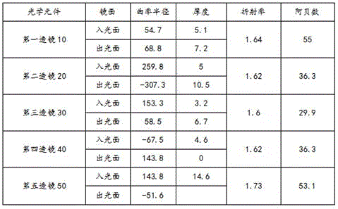
Wherein, the aspheric surface type expression of the third lens 30 is:

in the above formula, z is the sagittal height of the aspheric surface, r is the radius of the aspheric surface, i.e. r=sqrt (x 2 +y 2 ) K is a quadric coefficient, c is a curvature, A 4 ~A 16 The high order coefficients for the aspherical surfaces are shown in table 2.
TABLE 2

Wherein, each parameter to be described is as follows:
the focal length f of the projection lens is 142mm;
the focal length f1 of the first lens 10 is 364mm;
the focal length f2 of the second lens 20 is 225mm;
the focal length f3 of the third lens 30 is 161mm;
the focal length f4 of the fourth lens 40 is 116mm;
the focal length f5 of the fifth lens 50 is 69mm;
the lens thickness T1 of the first lens 10 along the optical axis direction is 5.1mm;
the lens thickness T2 of the second lens 20 along the optical axis direction is 5mm;
the thickness T3 of the third lens 30 in the optical axis direction is 3.2mm;
the lens thickness T4 of the fourth lens 40 in the optical axis direction is 4.6mm;
the thickness T5 of the fifth lens 50 along the optical axis direction is 14.6mm;
the total length TTL of the projection lens is 56.9 mm;
the projection lens has a view angle of 56 degrees, a design image height of 74.5, a focal length of 142mm, RI of more than or equal to 80%, wherein RI represents the ratio of edge illuminance to center illuminance, optical distortion is 0.39%, MTF of more than or equal to 0.3@10lp/mm, edge illuminance uniformity of 86% and maximum lens caliber phi 60. The design parameters of the lens are matched with the projection ratio of 1.0 when the size of the LCD is 5.7 inches; when the matched LCD is 4.5 inches, the off-axis amount can reach 100 percent.
Based on the above tables 1 and 2, analysis of the design results of the projection lens according to the embodiment of the present invention is provided below.
Referring to fig. 2, fig. 2 is a distortion chart corresponding to the projection lens of the present embodiment, wherein the ordinate of the distortion chart is the angle of view, and the abscissa of the distortion chart is the percentage. It can be seen that the distortion of the maximum field angle is less than 0.5%, indicating that the distortion of the projection lens is small.
Referring to fig. 3, fig. 3 is a graph of a modulation transfer function corresponding to the projection lens of the present embodiment, where the modulation transfer function (Modulation Transfer Function, MTF) refers to a relationship between a modulation degree and a logarithmic line per millimeter in an image, and is used for evaluating the reducing capability of details of a scene, and the larger the corresponding MTF value is, the better the larger the corresponding MTF value is under the same spatial frequency.
Referring to fig. 4, fig. 4 is a relative illuminance diagram corresponding to the projection lens of the present embodiment.
Fig. 2 to 4 are analysis of the design results of the projection lens, which can be used to evaluate the quality of the lens design. The projection lens of the embodiment can realize the effects of large field of view and short focal length, has small volume, light weight and high resolution, and can efficiently provide clear images.
The invention also provides an LCD projector, which comprises the large-field short-focus projection lens. The LCD projector adopts all the technical solutions of all the embodiments, so that the LCD projector has at least all the advantages brought by the technical solutions of the embodiments, and will not be described in detail herein.
The above examples represent only a few embodiments of the present application, which are described in more detail and are not to be construed as limiting the scope of the present application. It should be noted that it would be apparent to those skilled in the art that various modifications and improvements could be made without departing from the spirit of the present application, which would be within the scope of the present application.
Claims (9)
1. A large field of view short focus projection lens comprising:
the first lens, the second lens, the third lens, the fourth lens and the fifth lens are sequentially arranged along the light transmission direction; wherein the first lens, the second lens and the fifth lens all have positive focal power, and the third lens and the fourth lens all have negative focal power;
the light incident surface of the first lens along the optical axis direction is a convex surface, and the light emergent surface of the first lens along the optical axis direction is a concave surface;
the light incident surface and the light emergent surface of the second lens along the optical axis direction are convex;
the light incident surface and the light emergent surface of the third lens along the optical axis direction are concave surfaces;
the light incident surface and the light emergent surface of the fourth lens along the optical axis direction are concave surfaces;
the light incident surface and the light emergent surface of the fifth lens along the optical axis direction are convex.
2. The large field of view short focal projection lens of claim 1, wherein:
the light incident surface and the light emergent surface of the third lens are aspheric.
3. The large field of view short focus projection lens of claim 1, wherein the projection lens satisfies the relationship:
2.0≤f1/f≤3.0;
1.0≤f2/f≤2.0;
-1.5≤f3/f≤-0.5;
-1.0≤f4/f≤-0.5;
0.2≤f5/f≤0.7;
the f is a focal length of the projection lens, the f1 is a focal length of the first lens, the f2 is a focal length of the second lens, the f3 is a focal length of the third lens, the f4 is a focal length of the fourth lens, and the f5 is a focal length of the fifth lens.
4. The large field of view short focus projection lens of claim 1, wherein the projection lens satisfies the relationship:
1.0≤f1/f2≤2.0;
-2.5≤f1/f3≤-1.5;
-2.0≤f4/f5≤-1.0;
wherein f1 is a focal length of the first lens, f2 is a focal length of the second lens, f3 is a focal length of the third lens, f4 is a focal length of the fourth lens, and f5 is a focal length of the fifth lens.
5. The large field of view short focus projection lens of claim 1, wherein the projection lens satisfies the relationship:
1.70≥Nd1≥1.60;1.70≥Nd2≥1.60;1.65≥Nd3≥1.58;1.65≥Nd4≥1.60;1.75≥Nd5≥1.70;
wherein Nd1 is a refractive index of the first lens, nd2 is a refractive index of the second lens, nd3 is a refractive index of the third lens, nd4 is a refractive index of the fourth lens, and Nd5 is a refractive index of the fifth lens.
6. The large field of view short focus projection lens of claim 1, wherein the projection lens satisfies the relationship:
0.5≤T1/T2≤1.5;
0.5≤T3/T4≤2.0;
T3≥2.5mm;
T5≥10mm;
TTL≤65mm;
the TTL is the total length of the projection lens, T1 is the thickness of the lens of the first lens along the optical axis direction, T2 is the thickness of the lens of the second lens along the optical axis direction, T3 is the thickness of the lens of the third lens along the optical axis direction, T4 is the thickness of the lens of the fourth lens along the optical axis direction, and T5 is the thickness of the lens of the fifth lens along the optical axis direction.
7. The large field of view short focus projection lens of claim 1, wherein the projection lens satisfies the relationship:
6mm≤D12≤9mm,9mm≤D23≤12mm,5mm≤D34≤8mm;
wherein D12 is a distance between the light exit surface of the first lens and the light entrance surface of the second lens in the optical axis direction, D23 is a distance between the light exit surface of the second lens and the light entrance surface of the third lens in the optical axis direction, and D34 is a distance between the light exit surface of the third lens and the light entrance surface of the fourth lens in the optical axis direction.
8. The large field of view short focal projection lens of claim 1, wherein:
the light emergent surface of the fourth lens and the light incident surface of the fifth lens are mutually attached.
9. An LCD projector, comprising: a large field of view short focal projection lens as recited in any of claims 1-8.
Priority Applications (1)
| Application Number | Priority Date | Filing Date | Title |
|---|---|---|---|
| CN202310199203.7A CN116360077B (en) | 2023-03-03 | 2023-03-03 | Large-view-field short-focus projection lens and LCD projector |
Applications Claiming Priority (1)
| Application Number | Priority Date | Filing Date | Title |
|---|---|---|---|
| CN202310199203.7A CN116360077B (en) | 2023-03-03 | 2023-03-03 | Large-view-field short-focus projection lens and LCD projector |
Publications (2)
| Publication Number | Publication Date |
|---|---|
| CN116360077A true CN116360077A (en) | 2023-06-30 |
| CN116360077B CN116360077B (en) | 2023-11-03 |
Family
ID=86926630
Family Applications (1)
| Application Number | Title | Priority Date | Filing Date |
|---|---|---|---|
| CN202310199203.7A Active CN116360077B (en) | 2023-03-03 | 2023-03-03 | Large-view-field short-focus projection lens and LCD projector |
Country Status (1)
| Country | Link |
|---|---|
| CN (1) | CN116360077B (en) |
Citations (21)
| Publication number | Priority date | Publication date | Assignee | Title |
|---|---|---|---|---|
| JP2009294528A (en) * | 2008-06-06 | 2009-12-17 | Fujinon Corp | Imaging lens composed of five lenses and imaging apparatus |
| JP2010145591A (en) * | 2008-12-17 | 2010-07-01 | Deon Kogaku Giken:Kk | Ocular variable magnification sighting telescope |
| JP2011170074A (en) * | 2010-02-18 | 2011-09-01 | Sanyo Electric Co Ltd | Attachment lens and fluorescence measuring device to which the same is attached |
| US20110235171A1 (en) * | 2010-03-29 | 2011-09-29 | Olympus Corporation | Microscope adapter unit |
| JP2012194597A (en) * | 2012-07-19 | 2012-10-11 | Fujifilm Corp | Five-lens composition imaging lens and imaging apparatus |
| US20170085792A1 (en) * | 2014-05-06 | 2017-03-23 | Zakariya Niazi | Imaging system, method, and applications |
| US20170227744A1 (en) * | 2016-02-04 | 2017-08-10 | Seiko Epson Corporation | Projection system, projector, and conversion lens for projector |
| JP2017211474A (en) * | 2016-05-25 | 2017-11-30 | キヤノン株式会社 | Observation optical system and observation apparatus having the same |
| JP2018072739A (en) * | 2016-11-02 | 2018-05-10 | 株式会社栃木ニコン | Imaging lens, optical apparatus, and method for manufacturing plate-like member |
| CN110879456A (en) * | 2019-11-26 | 2020-03-13 | 歌尔股份有限公司 | Projection lens group, projection optical system and augmented reality equipment |
| CN112130297A (en) * | 2020-11-02 | 2020-12-25 | 东莞市长益光电有限公司 | Low-distortion fixed-focus lens with five lenses |
| CN113156624A (en) * | 2021-05-10 | 2021-07-23 | 天津欧菲光电有限公司 | Optical lens, camera module, electronic equipment and automobile |
| CN213934389U (en) * | 2020-09-27 | 2021-08-10 | 广州视享科技有限公司 | Projection optical device and head-mounted augmented reality equipment |
| US20210263264A1 (en) * | 2020-02-24 | 2021-08-26 | Aac Optics Solutions Pte. Ltd. | Camera optical lens |
| CN113970840A (en) * | 2021-12-27 | 2022-01-25 | 江西联创电子有限公司 | Optical lens |
| WO2022078023A1 (en) * | 2020-10-14 | 2022-04-21 | Oppo广东移动通信有限公司 | Lens, projector, and near-eye display system |
| WO2022078025A1 (en) * | 2020-10-14 | 2022-04-21 | Oppo广东移动通信有限公司 | Lens, projection optical machine, and near-eye display system |
| CN114415337A (en) * | 2022-01-27 | 2022-04-29 | 浙江舜宇光学有限公司 | Optical imaging lens |
| CN114815150A (en) * | 2022-04-08 | 2022-07-29 | 惠州市星聚宇光学有限公司 | Optical lens and optical lens module |
| CN217156945U (en) * | 2021-09-27 | 2022-08-09 | 广州视享科技有限公司 | Projection optical device and head-mounted augmented reality equipment |
| US20220326485A1 (en) * | 2021-03-31 | 2022-10-13 | Keiji Ikemori | Imaging optical system |
-
2023
- 2023-03-03 CN CN202310199203.7A patent/CN116360077B/en active Active
Patent Citations (21)
| Publication number | Priority date | Publication date | Assignee | Title |
|---|---|---|---|---|
| JP2009294528A (en) * | 2008-06-06 | 2009-12-17 | Fujinon Corp | Imaging lens composed of five lenses and imaging apparatus |
| JP2010145591A (en) * | 2008-12-17 | 2010-07-01 | Deon Kogaku Giken:Kk | Ocular variable magnification sighting telescope |
| JP2011170074A (en) * | 2010-02-18 | 2011-09-01 | Sanyo Electric Co Ltd | Attachment lens and fluorescence measuring device to which the same is attached |
| US20110235171A1 (en) * | 2010-03-29 | 2011-09-29 | Olympus Corporation | Microscope adapter unit |
| JP2012194597A (en) * | 2012-07-19 | 2012-10-11 | Fujifilm Corp | Five-lens composition imaging lens and imaging apparatus |
| US20170085792A1 (en) * | 2014-05-06 | 2017-03-23 | Zakariya Niazi | Imaging system, method, and applications |
| US20170227744A1 (en) * | 2016-02-04 | 2017-08-10 | Seiko Epson Corporation | Projection system, projector, and conversion lens for projector |
| JP2017211474A (en) * | 2016-05-25 | 2017-11-30 | キヤノン株式会社 | Observation optical system and observation apparatus having the same |
| JP2018072739A (en) * | 2016-11-02 | 2018-05-10 | 株式会社栃木ニコン | Imaging lens, optical apparatus, and method for manufacturing plate-like member |
| CN110879456A (en) * | 2019-11-26 | 2020-03-13 | 歌尔股份有限公司 | Projection lens group, projection optical system and augmented reality equipment |
| US20210263264A1 (en) * | 2020-02-24 | 2021-08-26 | Aac Optics Solutions Pte. Ltd. | Camera optical lens |
| CN213934389U (en) * | 2020-09-27 | 2021-08-10 | 广州视享科技有限公司 | Projection optical device and head-mounted augmented reality equipment |
| WO2022078023A1 (en) * | 2020-10-14 | 2022-04-21 | Oppo广东移动通信有限公司 | Lens, projector, and near-eye display system |
| WO2022078025A1 (en) * | 2020-10-14 | 2022-04-21 | Oppo广东移动通信有限公司 | Lens, projection optical machine, and near-eye display system |
| CN112130297A (en) * | 2020-11-02 | 2020-12-25 | 东莞市长益光电有限公司 | Low-distortion fixed-focus lens with five lenses |
| US20220326485A1 (en) * | 2021-03-31 | 2022-10-13 | Keiji Ikemori | Imaging optical system |
| CN113156624A (en) * | 2021-05-10 | 2021-07-23 | 天津欧菲光电有限公司 | Optical lens, camera module, electronic equipment and automobile |
| CN217156945U (en) * | 2021-09-27 | 2022-08-09 | 广州视享科技有限公司 | Projection optical device and head-mounted augmented reality equipment |
| CN113970840A (en) * | 2021-12-27 | 2022-01-25 | 江西联创电子有限公司 | Optical lens |
| CN114415337A (en) * | 2022-01-27 | 2022-04-29 | 浙江舜宇光学有限公司 | Optical imaging lens |
| CN114815150A (en) * | 2022-04-08 | 2022-07-29 | 惠州市星聚宇光学有限公司 | Optical lens and optical lens module |
Also Published As
| Publication number | Publication date |
|---|---|
| CN116360077B (en) | 2023-11-03 |
Similar Documents
| Publication | Publication Date | Title |
|---|---|---|
| CN113359277B (en) | Optical system and projection equipment | |
| CN111929816B (en) | High-definition aerial photographing optical system and lens | |
| CN118859491B (en) | Optical lens | |
| CN115453717A (en) | Optical lens module and virtual reality equipment | |
| CN112120650B (en) | An ultra-wide-angle steering endoscope lens | |
| CN117233924A (en) | A lens module, camera module and electronic equipment | |
| CN116360077B (en) | Large-view-field short-focus projection lens and LCD projector | |
| CN119414572B (en) | Multi-object-distance, low-distortion and high-definition machine vision lens and camera device | |
| CN119644560B (en) | Optical lens | |
| CN214540364U (en) | Automatic focusing ultra-short focus projection lens based on liquid lens | |
| CN220773329U (en) | Wide-angle optical lens | |
| CN115356828B (en) | A short-focus lens | |
| CN118226618A (en) | Optical lens | |
| CN213517720U (en) | a camera lens | |
| CN101210998B (en) | an optical lens | |
| CN110908225B (en) | Projection lens and projection equipment | |
| CN116027528B (en) | Coaxial telecentric optical imaging system, illumination system and imaging device | |
| CN114114614A (en) | Short-focus projection optical system | |
| CN222926908U (en) | Short-focus lens and LCD projector | |
| CN117310938B (en) | Projector lens | |
| CN215986698U (en) | Half picture camera lens of fisheye, camera module and shooting equipment | |
| CN112269240A (en) | Camera lens | |
| CN116482843B (en) | optical lens | |
| CN221528985U (en) | Projection assembly | |
| CN120178474B (en) | Optical lens |
Legal Events
| Date | Code | Title | Description |
|---|---|---|---|
| PB01 | Publication | ||
| PB01 | Publication | ||
| SE01 | Entry into force of request for substantive examination | ||
| SE01 | Entry into force of request for substantive examination | ||
| GR01 | Patent grant | ||
| GR01 | Patent grant |