CN1165103C - An automatic equalizing charging device for series battery packs - Google Patents
An automatic equalizing charging device for series battery packs Download PDFInfo
- Publication number
- CN1165103C CN1165103C CNB021003076A CN02100307A CN1165103C CN 1165103 C CN1165103 C CN 1165103C CN B021003076 A CNB021003076 A CN B021003076A CN 02100307 A CN02100307 A CN 02100307A CN 1165103 C CN1165103 C CN 1165103C
- Authority
- CN
- China
- Prior art keywords
- charging
- battery
- battery pack
- series
- voltage
- Prior art date
- Legal status (The legal status is an assumption and is not a legal conclusion. Google has not performed a legal analysis and makes no representation as to the accuracy of the status listed.)
- Expired - Fee Related
Links
Images

Landscapes
- Charge And Discharge Circuits For Batteries Or The Like (AREA)
Abstract
本发明是一种串联电池组自动均衡充电装置,它在由待充电的串联电池组(1)、电池电压信号实时采集与隔离电路(2)、主控制电路板(3)、逆变式充电电源(4)、电池电压巡检与显示电路(6)、温度传感器(7)、隔离驱动电路(8)和由功率开关(11)及由它构成的旁路分流网络(12)的现有均衡充电技术中,用MOS管(9)与功率电阻(10)串联构成的放电网络(5)代替现有技术中的功率开关(11)和由它构成的旁路分流网络(12),来实现对串联电池组(1)的充电速度快、安全可靠、达到串联电池组(1)的自动均衡。
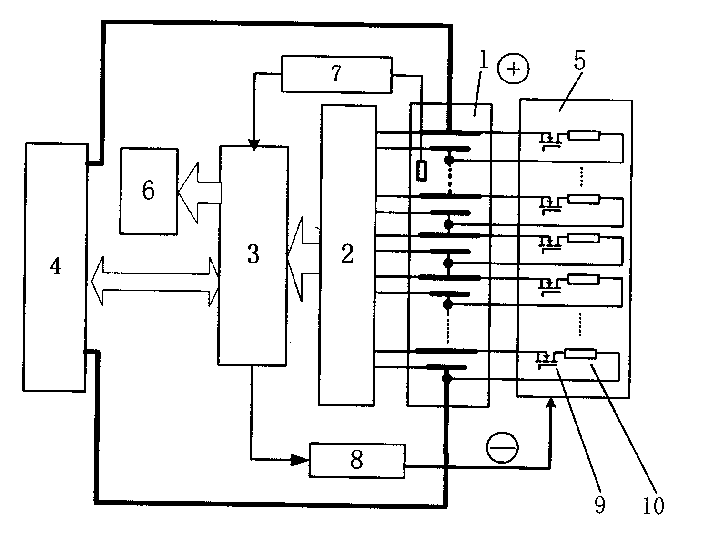
The present invention is an automatic balanced charging device for a series battery pack, which consists of a series battery pack to be charged (1), a battery voltage signal real-time acquisition and isolation circuit (2), a main control circuit board (3), an inverter charging Power supply (4), battery voltage inspection and display circuit (6), temperature sensor (7), isolation drive circuit (8) and the existing power switch (11) and bypass shunt network (12) formed by it In the balanced charging technology, the discharge network (5) composed of a MOS tube (9) and a power resistor (10) in series is used to replace the power switch (11) in the prior art and the bypass shunt network (12) formed by it, to Fast, safe and reliable charging of the series battery pack (1) is realized, and automatic equalization of the series battery pack (1) is achieved.
Description
技术领域technical field
本发明涉及在如电动汽车等各个领域的串联电池组的自动均衡充电装置。The invention relates to an automatic equalizing charging device for series battery packs in various fields such as electric vehicles.
背景技术Background technique
蓄电池广泛应用于各个领域,特别是近年来在电动汽车中,动力电池如锂离子电池,镍氢电池等被视为关键部件之一。对以串联工作方式的这些电池组进行充电时,如何保证充电过程中电池组的快速高效的自动均衡充电,是保证锂离子电池、镍氢电池安全和可靠性以及充分发挥其效能的一项关键技术。Batteries are widely used in various fields, especially in electric vehicles in recent years, power batteries such as lithium-ion batteries, nickel-metal hydride batteries, etc. are regarded as one of the key components. When charging these battery packs working in series, how to ensure fast and efficient automatic equalization charging of the battery packs during the charging process is a key to ensure the safety and reliability of lithium-ion batteries and nickel-metal hydride batteries and to give full play to their performance technology.
在已知的一种串联电池组充电装置,是充电电源的直流或脉动输出对串联电池组进行充电,输出电压和电流可调,该装置不能检测和控制单体电池的端电压,从而电池组的均衡性差,影响电池的使用寿命和效能。In a known series battery pack charging device, the DC or pulse output of the charging power supply charges the series battery pack, and the output voltage and current are adjustable. This device cannot detect and control the terminal voltage of the single battery, so that the battery pack The balance of the battery is poor, which affects the service life and performance of the battery.
在已知的另外一种串联电池组均衡充电装置,是对每个单体电池采用独立的充电系统,或采用一个充电电源带有多组直流输出,每组直流输出分别对一个单体电池进行充电。该方法简单可靠,但当电池组中单体电池数量较多时,则该方法实现起来太复杂,体积较大。Another known balance charging device for battery packs in series is to use an independent charging system for each single battery, or to use a charging power supply with multiple sets of DC outputs, and each set of DC outputs to charge a single battery respectively. Charge. This method is simple and reliable, but when the number of single cells in the battery pack is large, the method is too complicated to implement and has a large volume.
在已知的另外一种串联电池组均衡充电装置,是采用一套充电电源对串联电池组同时充电,并对每只单体电池的状态进行实时监控。当任一只单体电池达到预设的充电状态后即停止充电。停止充电方式主要有两种方式:一种方式是把达到预设充电状态的电池进行隔断,可采用接触器或功率电子开关,但该方式将在串联电池组中接入多个接触器触点或电子开关,势必影响串联电池组的工作可靠性,接入功率电子开关还将消耗大量电力,显著降低电池组的工作效率,并大大增加串联电池组的体积。第二种方式是对达到预设充电状态的单体电池的充电电流进行旁路分流,避免过充。这种方式则需要对旁路电流进行较为精确的控制,且牺牲一定的充电效率。Another known balancing charging device for series-connected battery packs uses a set of charging power sources to simultaneously charge the series-connected battery packs, and monitors the state of each single battery in real time. Charging stops when any single battery reaches the preset charging state. There are two main ways to stop charging: one way is to isolate the battery that has reached the preset charging state, and a contactor or power electronic switch can be used, but this way will connect multiple contactor contacts in the series battery pack Or the electronic switch will inevitably affect the working reliability of the series battery pack, and the access to the power electronic switch will also consume a large amount of power, significantly reduce the working efficiency of the battery pack, and greatly increase the volume of the series battery pack. The second method is to bypass and shunt the charging current of the single battery that reaches the preset charging state to avoid overcharging. This method requires more precise control of the bypass current and sacrifices a certain charging efficiency.
发明内容Contents of the invention
本发明的目的是提供一种与现有技术相比充电速度快、安全可靠,达到串联电池组自动均衡充电装置。The purpose of the present invention is to provide an automatic equalizing charging device for battery packs connected in series, which is fast in charging speed and safe and reliable compared with the prior art.
本发明是一种新型的串联电池组自动均衡充电装置。按照本发明,去掉了现有技术中的功率开关和由它组成的旁路分流网络,取而代之的是放电网络。其隔离驱动电路的每一个输出端连接在MOS管的控制端上,串联电池组的单体电池的正极连接在MOS管输入端上,MOS管的输出端连接功率电阻,功率电阻的另一端连接在串联电池组的单体电池的负极上。The invention is a novel automatic equalizing charging device for series battery packs. According to the present invention, the power switch in the prior art and the bypass shunt network composed of it are removed, and a discharge network is used instead. Each output terminal of the isolated drive circuit is connected to the control terminal of the MOS tube, the positive pole of the single battery of the series battery pack is connected to the input terminal of the MOS tube, the output terminal of the MOS tube is connected to the power resistor, and the other end of the power resistor is connected to the On the negative terminal of the single cells of the series battery pack.
附图说明Description of drawings
图1是现有技术中带有功率开关和由它组成的旁路分流网络的串联电池组均衡充电电路框图。Fig. 1 is a block diagram of a series-connected battery pack equalizing charging circuit with a power switch and a bypass shunt network composed of it in the prior art.
图2是本发明串联电池组自动均衡充电装置框图。Fig. 2 is a block diagram of an automatic equalizing charging device for series battery packs of the present invention.
具体实施方式Detailed ways
在表示现有技术串联电池组自动均衡充电装置电路框图的图1中,串联电池组1由仅有一组正负直流输出端的逆变式充电电源4充电,在充电时,串联电池组的各个单体电池的电流电压信号反馈到电池电压信号实时采集与隔离电路2,又经电池电压信号实时采集与隔离电路2将信号输入到主控制电路板3,与此同时,通过温度传感器7将充电电池的温度信号也输入到主控制电路板,主控制电路板3控制电池电压巡检与显示电路6显示各单体电池的电压,其控制信号又输入到充电电源4和隔离驱动电路8,由隔离驱动电路8将信号输入给串联电池组并联的功率开关11和由它构成的旁路分流网络12,从而控制充电电源的输出电流和输出电压,并控制对达到预设充电状态的单体电池的充电电流进行旁路分流,避免过充。In Fig. 1, which shows the circuit block diagram of an automatic equalizing charging device for series-connected battery packs in the prior art, the series-connected battery pack 1 is charged by an inverter
本发明串联电池组自动均衡充电装置,由一套待充电的串联电池组1,电池电压信号实时采集与隔离电路2,主控制电路板3,一个逆变式充电电源4,放电网络5,电池电压巡检与显示电路6,温度传感器7,隔离驱动电路8组成。The automatic equalization charging device for series battery packs of the present invention consists of a set of series battery packs 1 to be charged, a real-time acquisition and
待充电的串联电池组可以是锂离子充电电池,也可以是镍氢电池等。每个单体电池的容量可以是几百毫安时或几百安时,电池组中单体数量不限。The battery pack to be charged in series can be a lithium-ion rechargeable battery or a nickel-metal hydride battery. The capacity of each single battery can be hundreds of milliamp hours or hundreds of ampere hours, and the number of single cells in the battery pack is not limited.
电池电压信号实时采集与隔离电路2通过导线采集每一个单体电池的端电压,经放大处理,光电隔离后送至主控制电路板3。The battery voltage signal real-time collection and
主控制电路板3由微处理器和逻辑控制电路构成,接收电池电压信号实时采集与隔离电路2传来的每一个单体电池的端电压信号,以及温度传感器7传来的电池组的温度信号,控制充电电源的输出电流和输出电压,并控制放电网络对端电压值较高的电池单体进行适量放电,同时控制电池电压巡检与显示电路6显示各个单体电池的端电压。The main control circuit board 3 is composed of a microprocessor and a logic control circuit. It receives the battery voltage signal and collects and isolates the terminal voltage signal of each single battery in real time from the
充电电源是一种逆变式充电电源,主功率器件采用了IGBT(绝缘栅双极晶体管)模块,主电路由IGBT逆变电路组成,通过对输出电流、电压反馈,可实现对充电电源的输出外特性控制,从而实现对充电电流和充电电压的控制。充电电源的输出电流、电压视电池组的状态决定。The charging power supply is an inverter charging power supply. The main power device uses an IGBT (insulated gate bipolar transistor) module. The main circuit is composed of an IGBT inverter circuit. The output of the charging power supply can be realized by feedbacking the output current and voltage External characteristic control, so as to realize the control of charging current and charging voltage. The output current and voltage of the charging power supply depend on the state of the battery pack.
并联的放电网络5回路由MOS管9和串联的功率电阻10组成,由主控制电路板3隔离驱动开关MOS管控制放电回路放电。放电电流的大小由功率电组10的大小决定。电池电压巡检与显示电路6,通过巡检电路检测各个单体电池电压,数码管或液晶显示器显示。The parallel discharge network 5 circuit is composed of MOS transistor 9 and series connected power resistor 10, and the main control circuit board 3 isolates and drives the switch MOS transistor to control the discharge of the discharge circuit. The size of the discharge current is determined by the size of the power battery 10 . The battery voltage inspection and
串联电池组可以是锂离子充电电池,也可以是镍氢电池等。就某一种电池组而言,最大充电电流IM是指电池组可以承受的最大电流,在此电流下电池组温升不会过高,性能不被破坏;最高端电压VM是指单体电池可以充到的最高电压。The battery pack in series can be a lithium-ion rechargeable battery or a nickel-metal hydride battery. As far as a certain battery pack is concerned, the maximum charging current I M refers to the maximum current that the battery pack can withstand. Under this current, the temperature rise of the battery pack will not be too high and the performance will not be damaged; the highest end voltage V M refers to the single The highest voltage that the battery can be charged to.
本方案的具体充电程序如下所述:The specific charging procedure of this program is as follows:
先由主控板控制充电电源输出以最大充电电流IM对整个串联电池组进行充电,充电过程中对每一节电池的端电压进行监测,当检测到端电压最高的某一支单体电池的端电压接近最高端电压VM时,对端电压值较高的单体电池由主控板对其进行微量放电,对端电压较低的电池继续充电,这时可以适当减小充电电流。保证串联电池组中的电池端电压同步上升,最终同时充电到最高端电压VM,从而实现电池组均衡充电。First, the main control board controls the output of the charging power supply to charge the entire battery pack in series with the maximum charging current I M. During the charging process, the terminal voltage of each battery is monitored. When a single battery with the highest terminal voltage is detected When the terminal voltage of V is close to the highest terminal voltage V M , the main control board will discharge the single battery with higher opposite terminal voltage slightly, and the battery with lower opposite terminal voltage will continue to be charged. At this time, the charging current can be appropriately reduced. It is ensured that the terminal voltages of the batteries in the series battery pack rise synchronously, and are finally charged to the highest terminal voltage V M at the same time, so as to realize balanced charging of the battery pack.
本发明充电过程中,电池组的各个单体电池电压同步上升,实现了电池组的均衡化,同时充电过程始终保持较高的充电电流充电效率高。充电过程实现了智能化和自动化。In the charging process of the present invention, the voltage of each single cell of the battery pack rises synchronously, which realizes the equalization of the battery pack, and at the same time maintains a relatively high charging current and high charging efficiency during the charging process. The charging process is intelligent and automated.
充电过程设定的最终充电电压就是电池的最高端电压VM,当检测到电池电压高于最高端电压VM时,就对其进行放电,所以不会产生过充,确保了充电过程的安全。The final charging voltage set during the charging process is the highest voltage V M of the battery. When the battery voltage is detected to be higher than the highest voltage V M , it will be discharged, so there will be no overcharging, ensuring the safety of the charging process .
充电过程中,电池放电通过MOS开关管与功率电阻串联的方式进行。During the charging process, the battery discharge is carried out by connecting the MOS switch tube in series with the power resistor.
在充电过程中,为保证电池组的安全,必须对电池组的温度进行监控。在每一个电池组合中设置了一个温度传感器,对每一个电池组合均进行温度检测。温度传感信号输入主控板,充电过程中对电池的温度进行实时检测,当任何一个电池组合温度超过额定充电温度时,暂停充电(关闭充电电源输出)。During the charging process, in order to ensure the safety of the battery pack, the temperature of the battery pack must be monitored. A temperature sensor is set in each battery combination to detect the temperature of each battery combination. The temperature sensing signal is input to the main control board, and the temperature of the battery is detected in real time during the charging process. When the temperature of any battery combination exceeds the rated charging temperature, the charging is suspended (the output of the charging power supply is turned off).
该发明的特点:(1)对串联的电池组进行充电时,仅有一组正负直流输出端的逆变式充电电源直接对串联电池组进行充电,与同类充电器采用多组直流输出的方法相比,本发明体积小,重量轻,充电效率高。(2)充电过程中采用放电网络对于端电压较高的单体电池进行适量放电,使电池组中的各个单体电池的电压同步升高,同时充足,达到串联电池组的自动均衡。(3)充电过程设定的最终充电电压就是电池的最高端电压VM,当检测到电池电压高于最高端电压VM时,就对其进行放电,所以不会产生过充,确保了充电过程的安全。(4)充电过程中,对端电压较高的单体电池放电的同时充电过程继续进行,充电速度快,效率较高。The characteristics of the invention: (1) When charging the battery packs connected in series, only one set of inverter charging power sources with positive and negative DC output terminals directly charges the series battery packs, which is similar to the method in which multiple sets of DC outputs are used by similar chargers. Compared with the present invention, the volume is small, the weight is light, and the charging efficiency is high. (2) During the charging process, the discharge network is used to discharge the single battery with a higher terminal voltage in an appropriate amount, so that the voltage of each single battery in the battery pack increases synchronously and is sufficient at the same time to achieve automatic balance of the battery pack in series. (3) The final charging voltage set in the charging process is the highest terminal voltage V M of the battery. When the battery voltage is detected to be higher than the highest terminal voltage V M , it will be discharged, so overcharging will not occur, ensuring charging process safety. (4) During the charging process, the single battery with a higher terminal voltage is discharged while the charging process continues, and the charging speed is fast and the efficiency is high.
下面结合实际例子对本发明实施做进一步说明。The implementation of the present invention will be further described below in combination with practical examples.
待充电的锂离子动力电池串联电池组1共有84支单体电池组成,每支单体容量为55Ah(安·时),最大充电电流IM,电池的最高端电压VM为4.15V。电池组每个单体两端通过导线连接至电池电压信号实时采集与隔离放大电路2和放电网络5,隔离放大电路2将电压信号经光电隔离后送至主控制板3。充电电源4是逆变式充电电源,最大输出功率为3.5Kw,输出电流为0~10A。充电电源4的正输出端接电池组的正输入端,其负输出端接电池组的负输入端。放电网络5是由84支MOS管9和84支功率电阻10构成,分别并联在电池单体的两端。The lithium-ion power battery series battery pack 1 to be charged consists of 84 single cells, each with a capacity of 55Ah (Ah), the maximum charging current I M , and the highest terminal voltage V M of the battery is 4.15V. Both ends of each cell of the battery pack are connected to the battery voltage signal real-time acquisition and
其隔离驱动电路8的每一个输出端连接在MOS管9的控制端上,串联电池组1的单体电池的正极连接在MOS管9输入端上,MOS管9的输出端连接功率电阻10,功率电阻10的另一端连接在串联电池组1的单体电池的负极上。Each output end of the isolated drive circuit 8 is connected to the control end of the MOS transistor 9, the positive pole of the single battery of the series battery pack 1 is connected to the input end of the MOS transistor 9, and the output end of the MOS transistor 9 is connected to the power resistor 10, The other end of the power resistor 10 is connected to the negative pole of the single battery of the series battery pack 1 .
充电过程为:待充电池组的单体电压一般为3~4V,此时充电电流较大,可以为10A,由充电电源4提供恒定的直流输出。充电过程中由主控板对每一节电池的电压进行监测,并通过电池电压显示电路6显示出来,当检测到端电压最高的某一支单体电池的端电压接近最高端电压4.15V时,对端电压较高的单体电池由主控板3通过隔离驱动电路8驱动放电网络5对其进行微量放电,同时对于端电压较低的电池继续充电,这时可以适当减小充电电流。保证串联电池组中的电池端电压同步上升,最终同时充电到最高端电压VM,从而实现电池组均衡充电。通过放电网络进行定量的微量放电时,放电电流由放电网络的功率电阻决定,放电时间由主控板上的时间继电器控制。The charging process is as follows: the single voltage of the battery pack to be charged is generally 3-4V, at this time the charging current is relatively large, which can be 10A, and the charging
充电过程设定的最终充电电压就是电池的最高端电压4.15V,当检测到电池电压高于最高端电压4.15V时,就对其进行放电,所以不会产生过充,确保了充电过程的安全。The final charging voltage set during the charging process is the highest voltage of the battery 4.15V. When the battery voltage is detected to be higher than the highest voltage of 4.15V, it will be discharged, so there will be no overcharging, ensuring the safety of the charging process .
在充电过程中,为保证电池组的安全,在每一个电池组合中设置了一个温度传感电路7。温度传感信号输入主控制电路板3,充电过程中对电池的温度进行实时检测,当任何一个电池组合温度超过额定充电温度时,关闭充电电源暂停充电。In the charging process, in order to ensure the safety of the battery pack, a temperature sensing circuit 7 is set in each battery pack. The temperature sensing signal is input to the main control circuit board 3, and the temperature of the battery is detected in real time during the charging process. When the temperature of any battery combination exceeds the rated charging temperature, the charging power supply is turned off to suspend charging.
采用隔离放大器2对每一只电池电压进行检测,输入到主控板3,由主控板驱动电池电压巡检与显示电路6进行显示,便于观察。The
最终充电结果为:The final charging result is:
每个单体电池的端电压4.15V±0.02V。The terminal voltage of each single battery is 4.15V±0.02V.
充电过程稳定可靠,无温升过高现象。The charging process is stable and reliable, and there is no excessive temperature rise.
本发明采用仅有一组正负直流输出端的逆变式充电电源直接对串联电池组进行充电,与同类充电器采用多组直流输出的方法相比,本发明体积小,重量轻。充电过程中采用放电网络对端电压较高的单体电池进行适量放电,使电池组中的各个单体电池的电压同步升高,同时充足,达到串联电池组的自动均衡,安全可靠,提高了电池组的是使用效率和寿命。充电过程可以使用较高的充电电流,充电效率高。因此,本发明具有良好的应用价值。The present invention adopts only one set of positive and negative direct current output terminal inverter type charging power supply to directly charge the battery pack in series. Compared with the method of using multiple sets of direct current output by similar chargers, the present invention is small in size and light in weight. During the charging process, the discharge network is used to discharge the single battery with a higher terminal voltage in an appropriate amount, so that the voltage of each single battery in the battery pack rises synchronously and is sufficient at the same time to achieve automatic balance of the battery pack in series, which is safe and reliable, and improves the battery life. The battery pack is the service efficiency and life. The charging process can use a higher charging current, and the charging efficiency is high. Therefore, the present invention has good application value.
Claims (1)
Priority Applications (1)
| Application Number | Priority Date | Filing Date | Title |
|---|---|---|---|
| CNB021003076A CN1165103C (en) | 2002-01-07 | 2002-01-07 | An automatic equalizing charging device for series battery packs |
Applications Claiming Priority (1)
| Application Number | Priority Date | Filing Date | Title |
|---|---|---|---|
| CNB021003076A CN1165103C (en) | 2002-01-07 | 2002-01-07 | An automatic equalizing charging device for series battery packs |
Publications (2)
| Publication Number | Publication Date |
|---|---|
| CN1367565A CN1367565A (en) | 2002-09-04 |
| CN1165103C true CN1165103C (en) | 2004-09-01 |
Family
ID=4739294
Family Applications (1)
| Application Number | Title | Priority Date | Filing Date |
|---|---|---|---|
| CNB021003076A Expired - Fee Related CN1165103C (en) | 2002-01-07 | 2002-01-07 | An automatic equalizing charging device for series battery packs |
Country Status (1)
| Country | Link |
|---|---|
| CN (1) | CN1165103C (en) |
Cited By (1)
| Publication number | Priority date | Publication date | Assignee | Title |
|---|---|---|---|---|
| WO2012068734A1 (en) * | 2010-11-25 | 2012-05-31 | Kenneth Hamilton Norton | Battery management system and method |
Families Citing this family (47)
| Publication number | Priority date | Publication date | Assignee | Title |
|---|---|---|---|---|
| CN1332490C (en) * | 2002-12-06 | 2007-08-15 | 长沙交通学院 | Semiconductor refrigerating type equalizing charging method and device |
| JP2005110337A (en) * | 2003-09-26 | 2005-04-21 | Sanyo Electric Co Ltd | Multiple battery charger |
| CN100505471C (en) * | 2004-01-14 | 2009-06-24 | 财团法人工业技术研究院 | Equalizing circuit of series battery pack |
| JP4543714B2 (en) * | 2004-03-23 | 2010-09-15 | 日産自動車株式会社 | Capacity adjustment device and capacity adjustment method for battery pack |
| JP2005278242A (en) * | 2004-03-23 | 2005-10-06 | Nissan Motor Co Ltd | Capacity adjustment device and capacity adjustment method for battery pack |
| CN100559680C (en) * | 2005-01-18 | 2009-11-11 | 有量科技股份有限公司 | Lithium battery electric quantity balancing and charging method |
| CN100426620C (en) * | 2005-03-25 | 2008-10-15 | 苏州星恒电源有限公司 | Resistance calibrating method for lithium charge cell equalizing circuit |
| CN100375365C (en) * | 2005-06-30 | 2008-03-12 | 复旦大学 | A battery pack intelligent management circuit structure |
| US7466104B2 (en) * | 2006-10-13 | 2008-12-16 | O2 Micro International Limited | System and method for balancing cells in a battery pack with selective bypass paths |
| CN101960691B (en) * | 2008-02-29 | 2013-04-24 | 核心技术国际有限公司 | Charging device and quality judging device of pack cell |
| JP4965496B2 (en) * | 2008-04-01 | 2012-07-04 | セイコーインスツル株式会社 | Charge / discharge control circuit and battery device |
| TW200950255A (en) * | 2008-05-16 | 2009-12-01 | Cheng Uei Prec Ind Co Ltd | Charge control circuit |
| WO2010023527A2 (en) * | 2008-08-26 | 2010-03-04 | Panasonic Electric Works Co., Ltd. | Electric vehicle charging cord set |
| CN101789611B (en) * | 2009-01-24 | 2012-09-19 | 广达电脑股份有限公司 | Battery balancing device and method of operation thereof |
| CN101944642A (en) * | 2010-04-28 | 2011-01-12 | 浙江绿源电动车有限公司 | Battery device and battery containing device |
| CN201985554U (en) * | 2010-12-08 | 2011-09-21 | 夏正奎 | Active self-management charging device for lithium ion power battery |
| CN102064580A (en) * | 2010-12-14 | 2011-05-18 | 宁波飞驰达电子科技发展有限公司 | Series connected battery pack charging balance system and charging balance method thereof |
| US8922167B2 (en) * | 2011-01-20 | 2014-12-30 | Valence Technology, Inc. | Rechargeable battery systems and rechargeable battery system operational methods |
| US8957624B2 (en) | 2011-01-20 | 2015-02-17 | Valence Technology, Inc. | Rechargeable battery systems and rechargeable battery system operational methods |
| US8773068B2 (en) | 2011-01-20 | 2014-07-08 | Valence Technology, Inc. | Rechargeable battery systems and rechargeable battery system operational methods |
| US10536007B2 (en) | 2011-03-05 | 2020-01-14 | Powin Energy Corporation | Battery energy storage system and control system and applications thereof |
| US9847654B2 (en) | 2011-03-05 | 2017-12-19 | Powin Energy Corporation | Battery energy storage system and control system and applications thereof |
| US9331497B2 (en) | 2011-03-05 | 2016-05-03 | Powin Energy Corporation | Electrical energy storage unit and control system and applications thereof |
| AU2012249306B2 (en) * | 2011-04-28 | 2017-07-20 | Zoll Circulation, Inc. | Battery management system for control of lithium power cells |
| CN102916458B (en) | 2011-08-05 | 2015-06-17 | 凹凸电子(武汉)有限公司 | Battery equalizing system, circuit and method |
| CN103904708A (en) * | 2012-12-26 | 2014-07-02 | 电能有限公司 | Lithium battery provided with overcharging protection device in case of series charging |
| CN103633391A (en) * | 2013-11-29 | 2014-03-12 | 哈尔滨智木科技有限公司 | Electric vehicle battery pack with equalizing charge function |
| US10263436B2 (en) | 2014-10-20 | 2019-04-16 | Powin Energy Corporation | Electrical energy storage unit and control system and applications thereof |
| US10254350B2 (en) | 2015-08-06 | 2019-04-09 | Powin Energy Corporation | Warranty tracker for a battery pack |
| US10153521B2 (en) | 2015-08-06 | 2018-12-11 | Powin Energy Corporation | Systems and methods for detecting a battery pack having an operating issue or defect |
| US10122186B2 (en) | 2015-09-11 | 2018-11-06 | Powin Energy Corporation | Battery management systems (BMS) having isolated, distributed, daisy-chained battery module controllers |
| US9923247B2 (en) | 2015-09-11 | 2018-03-20 | Powin Energy Corporation | Battery pack with integrated battery management system |
| US10040363B2 (en) | 2015-10-15 | 2018-08-07 | Powin Energy Corporation | Battery-assisted electric vehicle charging system and method |
| US9882401B2 (en) | 2015-11-04 | 2018-01-30 | Powin Energy Corporation | Battery energy storage system |
| CN105978094A (en) * | 2016-06-23 | 2016-09-28 | 广州益维电动汽车有限公司 | Equalizing charge control system for lithium ion battery module |
| CN105895843B (en) * | 2016-06-23 | 2018-06-22 | 广州益维电动汽车有限公司 | A kind of intelligent lithium ion battery modules |
| CN105978100B (en) * | 2016-06-28 | 2019-04-19 | 简式国际汽车设计(北京)有限公司 | A battery bidirectional balancing circuit, system and balancing method |
| CN109936189B (en) * | 2016-07-08 | 2023-07-28 | 卓尔悦欧洲控股有限公司 | Equalizing charge circuit, device and method for series battery |
| CN106451588A (en) * | 2016-07-14 | 2017-02-22 | 苏州新逸喆电子科技有限公司 | Lithium battery pack equalizing charging method |
| US10699278B2 (en) | 2016-12-22 | 2020-06-30 | Powin Energy Corporation | Battery pack monitoring and warranty tracking system |
| CN106849253A (en) * | 2017-03-09 | 2017-06-13 | 上海空间电源研究所 | A kind of low orbit spacecraft high-voltage lithium ion battery equalising control device |
| KR102192188B1 (en) * | 2017-04-17 | 2020-12-16 | 주식회사 엘지화학 | Apparatus and method for preventing overcharge |
| CN107215221B (en) * | 2017-05-22 | 2023-09-05 | 惠州亿纬锂能股份有限公司 | Distributed Active Non-Dissipative Balancing Circuits for Series Battery Packs, Battery Packs and Automotive |
| US11114878B2 (en) | 2018-03-26 | 2021-09-07 | Milwaukee Electric Tool Corporation | High-power battery-powered portable power source |
| US11271415B2 (en) | 2018-05-18 | 2022-03-08 | Milwaukee Electric Tool Corporation | Portable power source |
| USD933010S1 (en) | 2019-05-29 | 2021-10-12 | Milwaukee Electric Tool Corporation | Portable power source |
| CN111313493A (en) * | 2019-11-30 | 2020-06-19 | 国网辽宁省电力有限公司葫芦岛供电公司 | A self-healing DC power protection device |
-
2002
- 2002-01-07 CN CNB021003076A patent/CN1165103C/en not_active Expired - Fee Related
Cited By (3)
| Publication number | Priority date | Publication date | Assignee | Title |
|---|---|---|---|---|
| WO2012068734A1 (en) * | 2010-11-25 | 2012-05-31 | Kenneth Hamilton Norton | Battery management system and method |
| GB2498149A (en) * | 2010-11-25 | 2013-07-03 | Cheevc Ltd | Battery management system and method |
| GB2498149B (en) * | 2010-11-25 | 2018-05-09 | Cheevc Ltd | Battery management system and method |
Also Published As
| Publication number | Publication date |
|---|---|
| CN1367565A (en) | 2002-09-04 |
Similar Documents
| Publication | Publication Date | Title |
|---|---|---|
| CN1165103C (en) | An automatic equalizing charging device for series battery packs | |
| CN1181593C (en) | Automatic equalization charging and discharging device based on battery dynamic power difference compensation | |
| CN101826745B (en) | Lithium ion power battery lossless charger | |
| CN1269256C (en) | Battery group for power supply of portable equipment | |
| CN201438493U (en) | Equilibrium device for vehicle power battery pack | |
| CN101976876A (en) | Device and method for equalizing batteries in charging process | |
| CN101192756A (en) | Balanced charging and discharging protection circuit and method for secondary battery | |
| CN103066671A (en) | Uniform charging method and uniform charging device for lithium battery packs | |
| CN1747278A (en) | Circuit for controlling series battery charge and discharge | |
| CN101795009B (en) | Battery charging device and method thereof | |
| CN201298740Y (en) | Equalizing charge apparatus for series battery set | |
| CN1315239C (en) | Battery with equalizing charge controlling circuit | |
| CN201766397U (en) | A power type multi-string lithium battery control system | |
| CN101471576A (en) | Charging method and apparatus | |
| CN107658925A (en) | The control system of battery modules | |
| CN2598788Y (en) | Charge and discharge management device for lithium secondary battery packs used to drive electric vehicles | |
| CN211701574U (en) | Self-equalizing charging device and charging control system | |
| CN109193863A (en) | Battery voltage balance control method and circuit | |
| CN2722489Y (en) | Automatic balanced recharging system of serial battery set | |
| CN204144993U (en) | A kind of electric automobile lithium battery charge balancing control circuit | |
| CN200944526Y (en) | Charging/discharging protection module of lithium power battery | |
| CN2662518Y (en) | Fast charger for nickel-hydrogen cell | |
| CN201556950U (en) | Battery balance charging and detection repair device | |
| CN211556939U (en) | Balance protection circuit for battery pack | |
| CN2508410Y (en) | Lithium ion battery capacity equalization charge and discharge controlling and protecting device |
Legal Events
| Date | Code | Title | Description |
|---|---|---|---|
| C10 | Entry into substantive examination | ||
| SE01 | Entry into force of request for substantive examination | ||
| C06 | Publication | ||
| PB01 | Publication | ||
| C10 | Entry into substantive examination | ||
| SE01 | Entry into force of request for substantive examination | ||
| C14 | Grant of patent or utility model | ||
| GR01 | Patent grant | ||
| C19 | Lapse of patent right due to non-payment of the annual fee | ||
| CF01 | Termination of patent right due to non-payment of annual fee |