CN1170660C - Shaving apparatus - Google Patents
Shaving apparatus Download PDFInfo
- Publication number
- CN1170660C CN1170660C CNB008166307A CN00816630A CN1170660C CN 1170660 C CN1170660 C CN 1170660C CN B008166307 A CNB008166307 A CN B008166307A CN 00816630 A CN00816630 A CN 00816630A CN 1170660 C CN1170660 C CN 1170660C
- Authority
- CN
- China
- Prior art keywords
- trimmer
- shaver
- spring
- housing
- shaver according
- Prior art date
- Legal status (The legal status is an assumption and is not a legal conclusion. Google has not performed a legal analysis and makes no representation as to the accuracy of the status listed.)
- Expired - Fee Related
Links
Images
Classifications
-
- B—PERFORMING OPERATIONS; TRANSPORTING
- B26—HAND CUTTING TOOLS; CUTTING; SEVERING
- B26B—HAND-HELD CUTTING TOOLS NOT OTHERWISE PROVIDED FOR
- B26B19/00—Clippers or shavers operating with a plurality of cutting edges, e.g. hair clippers, dry shavers
- B26B19/02—Clippers or shavers operating with a plurality of cutting edges, e.g. hair clippers, dry shavers of the reciprocating-cutter type
- B26B19/04—Cutting heads therefor; Cutters therefor; Securing equipment thereof
- B26B19/10—Cutting heads therefor; Cutters therefor; Securing equipment thereof involving two or more different types of reciprocating cutting elements, e.g. a pair of toothed shearing elements combined with a pair of perforated cutting elements or a combined toothed and perforated cutting assembly
- B26B19/102—Cutting heads therefor; Cutters therefor; Securing equipment thereof involving two or more different types of reciprocating cutting elements, e.g. a pair of toothed shearing elements combined with a pair of perforated cutting elements or a combined toothed and perforated cutting assembly with a secondary cutting unit being translated or slid into an operating position
Landscapes
- Life Sciences & Earth Sciences (AREA)
- Forests & Forestry (AREA)
- Engineering & Computer Science (AREA)
- Mechanical Engineering (AREA)
- Dry Shavers And Clippers (AREA)
Abstract
Description
技术领域technical field
本发明涉及一种剃须刀,该剃须刀带有至少一个设置在壳体里的电机、一个剃剪头、以及一个可调整设置的长发修剪装置或修剪器、以及一个操纵开关。The present invention relates to a shaver with at least one motor arranged in a housing, a shaving head, an adjustable setting long hair trimmer or trimmer, and an operating switch.
背景技术Background technique
电动剃须刀通常具有多个不同的修剪装置。除了与剃剪片共同作用的振摆的刀片组以外,已知许多其它的修剪装置,尤其是长发修剪装置。在此修剪器或长发修剪装置通常通过操纵开关被推进到一个其有效工作的位置,而且,还已知这样的长发修剪器,该长发修剪装置可从壳体面翻转并与振摆驱动装置连接。Electric shavers typically have several different trimming mechanisms. In addition to oscillating blade sets interacting with shaving blades, many other trimming devices are known, especially for long hair. The trimmer or the long hair trimming device is usually pushed into a position where it works effectively by manipulating the switch, and such long hair trimmers are also known, which can be turned over from the housing surface and driven with the vibration device connection.
对于这种修剪刀与梳齿共同作用的长发修剪装置,其结构是已知的,该长发修剪装置具有可移动的皮肤保护部件,以减少受伤的危险和损坏刀具的危险。由WO 98/07550已知这样一种长发修剪装置,该装置具有由上刀片以及下刀片的修剪齿所构成的修剪刃,皮肤保护部件可以通过一个单独的操纵元件相对于该长发修剪装置移动。因此,通过操作这个单独的操纵元件,皮肤保护部件可被置于皮肤保护部件上缘靠近修剪齿的位置,并进入修剪齿裸露的位置,由此更好地实现长发修剪效果。Designs are known for such long hair trimming devices in which the trimming blade cooperates with the teeth of the comb, which has a removable skin protection part to reduce the risk of injury and the risk of damage to the blade. Known such a long hair trimming device from WO 98/07550, this device has a trimming edge formed by the trimming teeth of the upper blade and the lower blade, the skin protection part can be relative to the long hair trimming device by a separate operating element move. Therefore, by operating this single manipulation element, the skin protection member can be placed at the position where the upper edge of the skin protection member is close to the trimming teeth, and into the position where the trimming teeth are exposed, thereby better achieving long hair trimming.
发明内容Contents of the invention
本发明的目的在于,提供一种上述形式的剃须刀,其中通过一个共用操纵开关可以得到多个工作位置,并且仅通过一个长发修剪装置或修剪器不仅可以起到第二剃剪头的作用而且可以起到长发修剪器的作用,而无需附加的修剪头。The object of the present invention is to provide a shaver of the above-mentioned form, wherein a plurality of working positions can be obtained by a common operating switch, and only one long hair trimming device or trimmer can not only play the role of the second shaving head function and can function as a long hair trimmer without the need for an additional trimming head.
为实现上述目的,本发明提供一种剃须刀,带有至少一个设置在壳体里的电机、一个剃剪头、以及一个可调整地设置的长发修剪装置或修剪器、以及一个操纵开关,其特征在于,所述操纵开关与所述修剪器机械地连接,而能同方向地运动,并且所述修剪器可以从一第一弹性支承的工作位置移动到一第二继续外伸的位置,并且修剪器的一个用作皮肤保护件的部件沿着移动方向被带动,经过比修剪器更小的移动行程直至一个止挡。To achieve the above object, the present invention provides a shaver with at least one motor arranged in the housing, a shaving head, and an adjustably arranged long hair trimming device or trimmer, and a manipulation switch , it is characterized in that the manipulation switch is mechanically connected with the trimmer and can move in the same direction, and the trimmer can move from a first elastically supported working position to a second continuously extended position , and a part of the trimmer serving as a skin protector is driven in the direction of movement through a smaller travel path than the trimmer until a stop is reached.
按照本发明的结构主要在于,操纵开关与修剪器机械地连接,而能同方向地运动,并且修剪器可以从一第一弹性支承的工作位置移动到一第二继续外伸的位置,并且修剪器的一个用作皮肤保护件的部件沿着移动方向被带动,经过比修剪器更小的移动行程直至一个止挡。由于将操纵开关与修剪器机械地连接成能同方向地运动,因此可以直接通过操作工作开关或操纵开关调整不同的工作状态,其中,在修剪器的第一工作位置,修剪器弹性地支承在壳体中并且可以起到第二剃剪装置的作用。由于将修剪器用工作开关或操纵开关移动到第二继续外伸的位置,因此可以将修剪器带入到一个可以将其用作长发修剪器的位置,而且,由于在这个移动过程中修剪器的用作皮肤保护件的部件沿着移动方向被带动,经过比修剪器更小的移动行程直至一个止挡而进入第二继续外伸的位置,因此直接使修剪器的修剪装置以相应的方式外露,以便形成一个有效的长发修剪装置。Mainly according to the structure of the present invention, the manipulation switch is mechanically connected with the trimmer, and can move in the same direction, and the trimmer can move from a first elastically supported working position to a second position that continues to protrude, and trim A part of the trimmer that acts as a skin protector is driven in the direction of movement over a smaller travel path than the trimmer up to a stop. Since the manipulation switch and the trimmer are mechanically connected to move in the same direction, different working states can be adjusted directly by operating the work switch or the manipulation switch, wherein, in the first working position of the trimmer, the trimmer is elastically supported on housing and can function as a second shaving unit. Since the trimmer is moved to the second position where the trimmer continues to extend with the work switch or the manipulation switch, the trimmer can be brought into a position that can be used as a long hair trimmer, and since the trimmer is in this moving process The part used as a skin protector is driven along the direction of movement through a smaller movement stroke than the trimmer until a stop and enters the second continued overhanging position, thus directly causing the trimming device of the trimmer to move in a corresponding manner exposed to form an effective trimming device for long hair.
在修剪器起到附加剃剪头作用的第一弹性支承的工作位置,修剪器以及剃剪片有利地可弹性变形,同时,有利地将修剪器设计成弹性地支承在修剪器壳体中的结构。In the working position of the first elastic support where the trimmer acts as an additional shaving head, the trimmer and the shaving blades are advantageously elastically deformable, and at the same time, the trimmer is advantageously designed to be elastically supported in the trimmer housing. structure.
有利地将修剪器设计成具有T形修剪刀的结构,其在移动方向上的T形架的法平面(normale Ebene)在第一工作位置弹性地固定在一个位置上,并基本与剃剪头的切平面(Tangentialebene)相重合,使得在这个第一弹性支承的工作位置形成一个基本上平面的包络线,这个包络线保证两个修剪装置与皮肤接触,而无需改变电动剃须刀的惯常操作。修剪器弹性地支承在其修剪器壳体中,以便在用手工将剃须刀偏转到不同的位置时,能够保证两个修剪装置同时工作。Advantageously the trimmer is designed as a structure with a T-shaped trimmer, the normal plane (normale Ebene) of the T-shaped frame in the direction of movement is elastically fixed in one position in the first working position, and substantially in line with the shaving head The tangent plane (Tangentialebene) coincides, so that a substantially planar envelope is formed in the working position of this first elastic support, and this envelope ensures that the two trimming devices are in contact with the skin without changing the position of the electric shaver. usual practice. The trimmer is elastically supported in its trimmer housing so that when the shaver is manually deflected to different positions, the simultaneous operation of the two trimming devices can be ensured.
在修剪器起到长发修剪装置作用的第二工作位置,修剪器继续外伸,使得在这个位置只使用修剪器,在这个位置皮肤保护件同时被拦阻,以便相应地露出修剪齿并保证能够可靠地捕获长发。在这种情况下,这样的结构是有利的,即,在修剪器的第二工作位置T形架在移动方向上的法平面位于高于平行于这个平面的剃剪头的切平面上。因为工作开关或操纵开关由于有限的壳体尺寸并为了简化操作通常只经过短的行程就从一个位置移动到下一个位置,而修剪器在第二工作位置的露出需要一个比操纵开关移动行程更大的修剪器移动行程,因此将修剪器设计成通过一个传动机构,尤其是肘形杠杆与操纵开关连接起来的结构是有利的。通过这种方式可以实现在工作开关或操纵开关只移动4mm时使修剪器外伸超过7mm,同时通过限制皮肤保护件的行程相应地实现修剪齿外露。In the second operating position where the trimmer plays the role of the long hair trimming device, the trimmer continues to stretch out, so that only the trimmer is used in this position, and the skin protector is blocked at the same time in this position, so that the trimming teeth are exposed accordingly and it is guaranteed to be able to Reliably captures long hair. In this case, it is advantageous that the normal plane of the T-bar in the direction of movement in the second working position of the trimmer lies above the tangential plane of the shaving head parallel to this plane. Because the working switch or the operating switch is due to the limited housing size and usually only moves from one position to the next position through a short stroke in order to simplify the operation, and the exposure of the trimmer at the second working position requires a longer stroke than the operating switch. The large trimmer moves the stroke, so it is beneficial to design the trimmer as a structure that is connected to the control switch through a transmission mechanism, especially an elbow lever. In this way, it is possible to make the trimmer overhang by more than 7 mm when the operating switch or the control switch is only moved by 4 mm, and at the same time the trimming teeth are exposed correspondingly by limiting the stroke of the skin protector.
在修剪器要作为长发修剪装置使用的第二工作位置,不希望修剪器具有弹性。因此这样的结构是有利的,即,修剪器在其第二工作位置力锁合或摩擦锁合地与止挡共同作用,该止挡限定修剪器的弹性移动。In the second working position where the trimmer is to be used as a long hair trimming device, it is not desirable for the trimmer to be elastic. It is therefore advantageous if the trimmer cooperates in its second operating position in a non-positive or frictional manner with a stop which limits the elastic displacement of the trimmer.
为了保证在拉回修剪器时通过与操纵开关共同作用的操纵元件可靠地产生移动行程的返回移动,将修剪器壳体设计成在其外伸的第二位置压靠在弹簧上是有利的,弹簧的弹簧行程相当于第一位置与第二位置之间的移动行程。因此,当拉回操纵开关时,修剪器壳体通过这个弹簧的力返回到初始位置,在这个位置又实现修剪器在修剪器壳体中的弹性悬挂和支承。In order to ensure that the return movement of the displacement stroke is reliably produced by the actuating element cooperating with the actuating switch when the trimmer is pulled back, it is advantageous to design the trimmer housing to bear against the spring in its protruding second position, The spring travel of the spring corresponds to the travel travel between the first position and the second position. Therefore, when the manipulation switch is pulled back, the trimmer housing returns to the initial position by the force of the spring, and at this position the elastic suspension and support of the trimmer in the trimmer housing is realized again.
为了在修剪器的第一弹性支承的工作位置限定皮肤保护件向外的行程,将皮肤保护件设计成与修剪器的外露梳齿搭接的结构是有利的。通过这种方式,当修剪器向内移动时,与皮肤保护件搭接的外露梳齿又带动皮肤保护件运动,使皮肤保护件到达其相对于修剪器更外面的位置,在这个位置减少了受伤的危险。为了有利于皮肤保护件相对于修剪器移动到这个初始位置,将用作皮肤保护件的部件设计成可以克服支承在修剪器上的弹簧的力而被带动到其向外的终端位置是有利的。可以以特别简单的方式将弹性支承在修剪器壳体内的修剪器通过可沿这个弹簧的力方向与修剪器一起移动的执行元件与操纵开关共同作用,同时确保这个执行元件的这样一种作用方向,即,在向外移动的第二继续外伸位置使弹簧的作用被限定并且使修剪器直接支承在执行元件上。通过这种方式保证在第二继续外伸的位置使用修剪器时不再产生弹性变形,以有利于作为长发修剪装置使用。In order to limit the outward travel of the skin protector in the first elastically supported working position of the trimmer, it is advantageous to design the skin protector to overlap the exposed comb teeth of the trimmer. In this way, when the trimmer moves inwards, the exposed teeth overlapping the skin protector move the skin protector to its outer position relative to the trimmer, where the Risk of injury. In order to facilitate the movement of the skin protector relative to the trimmer to this initial position, it is advantageous to design the part serving as the skin protector so that it can be brought into its outward end position against the force of a spring bearing on the trimmer. . In a particularly simple manner, the trimmer, which is elastically supported in the trimmer housing, can interact with the actuating switch via an actuator which can move together with the trimmer in the direction of force of the spring, while ensuring such an action direction of the actuator , That is, in the outwardly moved second continued extension position the effect of the spring is limited and the trimmer is directly supported on the actuator. In this way, it is ensured that no elastic deformation will occur when the trimmer is used at the second position that continues to protrude, so that it can be used as a long hair trimming device.
优选地,将修剪器的用作皮肤保护件的部件设计成梳齿,同时也可以在面对剃剪头的修剪器一侧设置梳齿。但是也可以采用一种毛发梳理部件(Haaraufrichtelement)代替设置在面对剃剪头的修剪器一侧的梳齿,该毛发梳理部件例如由薄片或软塑料制成。Preferably, the part of the trimmer serving as a skin protector is designed as comb teeth, while comb teeth can also be provided on the side of the trimmer facing the shaving head. However, instead of the combs arranged on the side of the trimmer facing the shaving head, a hair combing element, for example made of a foil or soft plastic, can be used.
附图说明Description of drawings
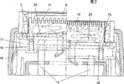
下面借助于一个在附图中简示的实施例来详细地描述本发明。图1示出剃须刀的前视图,操纵开关处于断开位置,其中剃剪装置在工作状态基本保持在同一位置;图2示出图1视图的侧视图;图3对应于图1的前视图,但是操纵开关处于使修剪器外伸的位置;图4为图3视图的侧视图;图5示出图2的V-V剖面;图6示出图4中VI-VI剖面;而图7示出沿修剪刀振摆修剪运动方向的剃剪头局部剖视图,其中这些部件局部用剖面示出。The invention is described in more detail below with the aid of an exemplary embodiment which is schematically illustrated in the drawing. Fig. 1 shows the front view of the shaver, the operating switch is in the off position, wherein the shaving and clipping device remains in the same position substantially in the working state; Fig. 2 shows the side view of Fig. 1 view; Fig. 3 corresponds to the front view of Fig. 1 view, but the manipulation switch is in the position that the trimmer is extended; Fig. 4 is a side view of Fig. 3 view; Fig. 5 shows the V-V section of Fig. 2; Fig. 6 shows the VI-VI section in Fig. 4; and Fig. 7 shows A partial sectional view of the shaving head along the vibrating trimming movement direction of the trimmer is shown, wherein these components are partially shown in section.
具体实施方式Detailed ways
在图1中示出电动剃须刀1,其操纵开关用2表示。操纵开关可以沿双箭头3方向上下移动,其中对断开位置附加一第一工作位置和一第二位置,在第二位置修剪器外伸。剃剪头用4表示,并且还示出一个修剪器5,只要操纵开关处于断开位置或第一工作位置,该修剪器就可以在图1所示的位置之间弹性地上下移动。在图2的视图中除了用5来简化表示的修剪器以外还表示出剃剪装置剃剪片的外轮廓6。在图3的视图中操纵开关2被向上推到其第二工作位置,在这个位置修剪器5到达其外伸位置,尤其如同在图4侧视图中所表示的那样。FIG. 1 shows an
在图5、6和7中的放大剖面图中进一步表明推动操纵开关2时的移动过程。这里用7来简化表示位于剃须刀1壳体中的一个驱动电机,该驱动电机不仅驱动一个与剃剪片6共同作用的刀刃组8,而且驱使修剪器5内部的一个修剪刀9产生振摆运动。一个执行元件10通过一个相应的传动机构与操纵开关2连接。修剪器5本身弹性地支承在一个修剪器壳体中并且在这个位置可以克服弹簧力向内移动。The movement process when the
在图5的视图中表示出用作皮肤保护件11的部件,如图5所示,该部件在第一工作位置相对于修剪器5向外移动并与修剪器5的上缘或与外梳齿12共同作用。皮肤保护件11具有一个突起13,该突起在第一工作位置以及断开位置位于一个自由空间14中,由此使修剪器5连同皮肤保护件11能够没有阻碍地向内弹动。Shown in the view of Fig. 5 as the parts of
如图6所示,通过操作操纵开关2则使执行元件10移动到上面的位置。当修剪器5向外移动时,皮肤保护件11到达第二工作位置,通过其突起13止挡在头部4的一个向内凸出的凸台15上而由这个止挡拦阻,此时,修剪器5沿着与其移动方向对应的双箭头16方向可以继续向外移动。在图6所示的第二位置,修剪器刚性地支承,并由于止挡13和15而使皮肤保护件11相对于梳齿12处于缩回的位置,这个位置使修剪齿更好地露出。As shown in FIG. 6 , the
在图7中再一次详细地表示出修剪器的两个工作位置。修剪器5通过压力弹簧18的中转连接而弹性地支承在修剪器壳体17中,因此修剪器在右边图示的第一工作位置可以克服该弹簧18的弹簧力向内移动,以保证修剪器弹性地贴靠在皮肤上。设计成叉状的执行元件10直接操作修剪器,即,这个执行元件10经过一预定行程后,贴靠在修剪器上并使修剪器向外移动。通过使执行元件10贴靠在修剪器5上,由弹簧18实现弹性锁定,而修剪器5可以到达图7左边所示的向外移动的第二工作位置。在这个第二工作位置,也就是壳体17被带动到的位置,弹簧19被施加预应力,在拉回执行元件10之后,该弹簧使壳体17拉回并因此使修剪器5拉回,同时,在图7右边所示的位置中,依压力弹簧18释放的相应行程而释放相应的弹簧行程。The two working positions of the trimmer are again shown in detail in FIG. 7 . The
在向外移动修剪器5时,皮肤保护件11的一个止挡与一个可弹性变形的臂20共同作用,如图6所示,这个皮肤保护件同时被头部的止挡15拦阻。这个弹性臂20在壳体17和修剪器5拉回到第一工作位置时又被放松而处在图7所示的右边位置,在这个位置,皮肤保护件11又逆着上梳齿12自动移动到其向外的位置上。When moving the
Claims (12)
Applications Claiming Priority (2)
| Application Number | Priority Date | Filing Date | Title |
|---|---|---|---|
| ATGM839/1999 | 1999-12-03 | ||
| AT83999 | 1999-12-03 |
Publications (2)
| Publication Number | Publication Date |
|---|---|
| CN1420811A CN1420811A (en) | 2003-05-28 |
| CN1170660C true CN1170660C (en) | 2004-10-13 |
Family
ID=3500968
Family Applications (1)
| Application Number | Title | Priority Date | Filing Date |
|---|---|---|---|
| CNB008166307A Expired - Fee Related CN1170660C (en) | 1999-12-03 | 2000-12-01 | Shaving apparatus |
Country Status (7)
| Country | Link |
|---|---|
| US (1) | US6739054B2 (en) |
| EP (1) | EP1233850B1 (en) |
| JP (1) | JP2004500172A (en) |
| CN (1) | CN1170660C (en) |
| AT (1) | ATE265915T1 (en) |
| DE (1) | DE50006356D1 (en) |
| WO (1) | WO2001039936A1 (en) |
Families Citing this family (16)
| Publication number | Priority date | Publication date | Assignee | Title |
|---|---|---|---|---|
| JP4161966B2 (en) * | 2002-06-17 | 2008-10-08 | 松下電工株式会社 | Electric razor |
| AT7596U1 (en) * | 2003-07-01 | 2005-06-27 | Payer Int Technologies Gmbh | epilation device |
| JP4729487B2 (en) * | 2003-07-04 | 2011-07-20 | コーニンクレッカ フィリップス エレクトロニクス エヌ ヴィ | Shaving device having a shaving head mounted for rotation |
| JP2005052466A (en) * | 2003-08-06 | 2005-03-03 | Izumi Products Co | Electric razor |
| USD523586S1 (en) * | 2005-05-18 | 2006-06-20 | Matsushita Electric Works, Ltd. | Electric shaver |
| JP4888882B2 (en) * | 2005-10-13 | 2012-02-29 | 九州日立マクセル株式会社 | Clippers |
| US8578563B2 (en) * | 2006-06-27 | 2013-11-12 | Comfortglide, Inc. | Tool system with replaceable heads and offset handle |
| US7540087B2 (en) * | 2006-07-14 | 2009-06-02 | The Gillette Company | Shaving razor |
| US8065774B2 (en) | 2006-10-26 | 2011-11-29 | Margco International, Llc | Paint brush with detachable head |
| US8261398B2 (en) | 2006-10-26 | 2012-09-11 | Margco International, Llc | Paint brush with detachable head |
| EP2114637A1 (en) * | 2007-02-01 | 2009-11-11 | Braun GmbH | Hair removal device |
| DE102007050379A1 (en) | 2007-10-22 | 2009-04-23 | Braun Gmbh | hair trimmer |
| DE102007050381A1 (en) * | 2007-10-22 | 2009-04-23 | Braun Gmbh | Hair removal device |
| EP2329928B1 (en) * | 2009-12-04 | 2012-07-04 | Braun GmbH | Electrically operated hair cutting device |
| CN105014702B (en) * | 2015-07-15 | 2017-01-18 | 宁波真和电器股份有限公司 | Tool bit of electric shaver, electric shaver and using method of electric shaver |
| EP4108396A1 (en) * | 2021-06-22 | 2022-12-28 | BaByliss Faco sprl | Beard trimmer with suspension system for the cutting unit |
Family Cites Families (9)
| Publication number | Priority date | Publication date | Assignee | Title |
|---|---|---|---|---|
| US3781990A (en) * | 1970-06-08 | 1974-01-01 | Philips Corp | Dry shaver with selectively engagable short and long hair cutters |
| NL7405870A (en) | 1974-05-02 | 1975-11-04 | Philips Nv | DRY SHAVER WITH EXTENDABLE CLIPPER. |
| AT368057B (en) * | 1980-04-03 | 1982-09-10 | Payer Lux Elektroprod | ELECTRIC SHAVER |
| US4803780A (en) * | 1986-09-17 | 1989-02-14 | Remington Products, Inc. | Electric dry shaver having an improved trimmer arrangement |
| JPS63160691A (en) * | 1986-12-23 | 1988-07-04 | 松下電工株式会社 | Electric razor |
| DE4117990A1 (en) | 1991-06-03 | 1992-12-10 | Braun Ag | ELECTRIC SHAVER |
| CN1098146C (en) * | 1996-06-25 | 2003-01-08 | 松下电工株式会社 | Electric shaver |
| DE19633824C1 (en) * | 1996-08-22 | 1997-06-05 | Braun Ag | Electrically powered shaver |
| DE19822094C2 (en) * | 1998-05-16 | 2000-03-02 | Braun Gmbh | Dry shaver |
-
2000
- 2000-12-01 DE DE50006356T patent/DE50006356D1/en not_active Expired - Lifetime
- 2000-12-01 WO PCT/AT2000/000323 patent/WO2001039936A1/en not_active Ceased
- 2000-12-01 US US10/148,314 patent/US6739054B2/en not_active Expired - Fee Related
- 2000-12-01 CN CNB008166307A patent/CN1170660C/en not_active Expired - Fee Related
- 2000-12-01 EP EP00979246A patent/EP1233850B1/en not_active Expired - Lifetime
- 2000-12-01 JP JP2001541654A patent/JP2004500172A/en active Pending
- 2000-12-01 AT AT00979246T patent/ATE265915T1/en not_active IP Right Cessation
Also Published As
| Publication number | Publication date |
|---|---|
| US6739054B2 (en) | 2004-05-25 |
| DE50006356D1 (en) | 2004-06-09 |
| EP1233850B1 (en) | 2004-05-06 |
| US20020178586A1 (en) | 2002-12-05 |
| WO2001039936A1 (en) | 2001-06-07 |
| CN1420811A (en) | 2003-05-28 |
| JP2004500172A (en) | 2004-01-08 |
| ATE265915T1 (en) | 2004-05-15 |
| EP1233850A1 (en) | 2002-08-28 |
Similar Documents
| Publication | Publication Date | Title |
|---|---|---|
| CN1170660C (en) | Shaving apparatus | |
| EP3907046B1 (en) | Electric beard trimmer | |
| RU2675414C2 (en) | Hair clipping device | |
| JP4927176B2 (en) | Hair removal device | |
| US5054199A (en) | Hair cutter | |
| EP1744859B2 (en) | Wet razor and electric trimmer assembly | |
| EP1732736B1 (en) | Shaving apparatus | |
| RU2689350C2 (en) | Hair clipper | |
| CN107520862B (en) | Electric razors and external knives used for the electric razors | |
| WO2012029043A1 (en) | Shaving head with multiple shaving units | |
| CN1816426A (en) | Electrical hair cutting appliance | |
| DE59604732D1 (en) | Dry shaver with pivoting long hair trimmer | |
| JP2015142782A (en) | Shaving unit for electric razor | |
| JP7018521B2 (en) | Hair cutting device | |
| KR20030027121A (en) | Shaving systems and adjustable trimmers therefor | |
| CN1225050A (en) | electric shaver | |
| CN1021208C (en) | Electric shaver | |
| JP3363151B2 (en) | Electric shaving equipment | |
| JP5122302B2 (en) | Electric hair trimmer | |
| NL7909059A (en) | SHAVER. | |
| CN111941467B (en) | Interleaved multi-layer trimming head for electric hair clippers | |
| JP5879531B2 (en) | Electric razor | |
| US2402233A (en) | Dry shaver | |
| CN222755509U (en) | Elastic hair trimmer moves sword guide slide | |
| JP2002273072A (en) | Electric shaver |
Legal Events
| Date | Code | Title | Description |
|---|---|---|---|
| C06 | Publication | ||
| PB01 | Publication | ||
| C10 | Entry into substantive examination | ||
| SE01 | Entry into force of request for substantive examination | ||
| C14 | Grant of patent or utility model | ||
| GR01 | Patent grant | ||
| C56 | Change in the name or address of the patentee |
Owner name: PYLE INTERNATIONAL TECHNOLOGY CO., LTD. Free format text: FORMER NAME OR ADDRESS: PYLE INTERNATIONAL TECHNOLOGY PARTENERSHIP CO.,LTD. |
|
| CP03 | Change of name, title or address |
Address after: Austria bartholoma Patentee after: Pyle International Technology Ltd Address before: Austria bartholoma Patentee before: Payer International Technology GmbH & Co. KG |
|
| C17 | Cessation of patent right | ||
| CF01 | Termination of patent right due to non-payment of annual fee |
Granted publication date: 20041013 Termination date: 20101201 |