CN1170664A - Method and apparatus for spraying liquid by gas bubble communication with atmosphere - Google Patents
Method and apparatus for spraying liquid by gas bubble communication with atmosphere Download PDFInfo
- Publication number
- CN1170664A CN1170664A CN97114931A CN97114931A CN1170664A CN 1170664 A CN1170664 A CN 1170664A CN 97114931 A CN97114931 A CN 97114931A CN 97114931 A CN97114931 A CN 97114931A CN 1170664 A CN1170664 A CN 1170664A
- Authority
- CN
- China
- Prior art keywords
- liquid
- bubble
- atmosphere
- communicated
- spout
- Prior art date
- Legal status (The legal status is an assumption and is not a legal conclusion. Google has not performed a legal analysis and makes no representation as to the accuracy of the status listed.)
- Granted
Links
- 239000007788 liquid Substances 0.000 title claims abstract description 636
- 239000012298 atmosphere Substances 0.000 title claims abstract description 78
- 238000000034 method Methods 0.000 title claims abstract description 57
- 238000004891 communication Methods 0.000 title abstract description 24
- 230000006854 communication Effects 0.000 title abstract description 22
- 238000005507 spraying Methods 0.000 title abstract description 13
- 230000008569 process Effects 0.000 claims abstract description 11
- 239000000758 substrate Substances 0.000 claims description 42
- 239000007921 spray Substances 0.000 claims description 30
- 238000002347 injection Methods 0.000 claims description 28
- 239000007924 injection Substances 0.000 claims description 28
- 239000012530 fluid Substances 0.000 claims description 21
- 238000011144 upstream manufacturing Methods 0.000 claims description 19
- 238000005530 etching Methods 0.000 claims description 8
- 230000007246 mechanism Effects 0.000 claims description 8
- 238000006073 displacement reaction Methods 0.000 claims description 5
- 238000010438 heat treatment Methods 0.000 description 114
- 239000000976 ink Substances 0.000 description 28
- 238000005192 partition Methods 0.000 description 26
- 230000005540 biological transmission Effects 0.000 description 16
- 238000004519 manufacturing process Methods 0.000 description 15
- 230000005499 meniscus Effects 0.000 description 15
- 230000015572 biosynthetic process Effects 0.000 description 10
- 229910052782 aluminium Inorganic materials 0.000 description 9
- XAGFODPZIPBFFR-UHFFFAOYSA-N aluminium Chemical compound [Al] XAGFODPZIPBFFR-UHFFFAOYSA-N 0.000 description 9
- 229910052751 metal Inorganic materials 0.000 description 9
- 239000002184 metal Substances 0.000 description 9
- PXHVJJICTQNCMI-UHFFFAOYSA-N Nickel Chemical compound [Ni] PXHVJJICTQNCMI-UHFFFAOYSA-N 0.000 description 8
- 238000009835 boiling Methods 0.000 description 8
- 238000010586 diagram Methods 0.000 description 8
- 230000009471 action Effects 0.000 description 7
- 230000002441 reversible effect Effects 0.000 description 7
- 238000009826 distribution Methods 0.000 description 6
- 239000000463 material Substances 0.000 description 6
- 239000000203 mixture Substances 0.000 description 6
- 238000013461 design Methods 0.000 description 5
- 239000004744 fabric Substances 0.000 description 5
- 239000004033 plastic Substances 0.000 description 5
- 229920003023 plastic Polymers 0.000 description 5
- 229920005989 resin Polymers 0.000 description 5
- 239000011347 resin Substances 0.000 description 5
- LFQSCWFLJHTTHZ-UHFFFAOYSA-N Ethanol Chemical compound CCO LFQSCWFLJHTTHZ-UHFFFAOYSA-N 0.000 description 4
- 239000000919 ceramic Substances 0.000 description 4
- 230000000694 effects Effects 0.000 description 4
- 230000005611 electricity Effects 0.000 description 4
- 239000010985 leather Substances 0.000 description 4
- 229910052759 nickel Inorganic materials 0.000 description 4
- 238000000059 patterning Methods 0.000 description 4
- 229920001296 polysiloxane Polymers 0.000 description 4
- 238000012545 processing Methods 0.000 description 4
- -1 silk Substances 0.000 description 4
- 239000000243 solution Substances 0.000 description 4
- 238000012546 transfer Methods 0.000 description 4
- 239000002023 wood Substances 0.000 description 4
- ZWEHNKRNPOVVGH-UHFFFAOYSA-N 2-Butanone Chemical compound CCC(C)=O ZWEHNKRNPOVVGH-UHFFFAOYSA-N 0.000 description 3
- CSCPPACGZOOCGX-UHFFFAOYSA-N Acetone Chemical compound CC(C)=O CSCPPACGZOOCGX-UHFFFAOYSA-N 0.000 description 3
- YMWUJEATGCHHMB-UHFFFAOYSA-N Dichloromethane Chemical compound ClCCl YMWUJEATGCHHMB-UHFFFAOYSA-N 0.000 description 3
- RTZKZFJDLAIYFH-UHFFFAOYSA-N Diethyl ether Chemical compound CCOCC RTZKZFJDLAIYFH-UHFFFAOYSA-N 0.000 description 3
- XEKOWRVHYACXOJ-UHFFFAOYSA-N Ethyl acetate Chemical compound CCOC(C)=O XEKOWRVHYACXOJ-UHFFFAOYSA-N 0.000 description 3
- OKKJLVBELUTLKV-UHFFFAOYSA-N Methanol Chemical compound OC OKKJLVBELUTLKV-UHFFFAOYSA-N 0.000 description 3
- IMNFDUFMRHMDMM-UHFFFAOYSA-N N-Heptane Chemical compound CCCCCCC IMNFDUFMRHMDMM-UHFFFAOYSA-N 0.000 description 3
- YXFVVABEGXRONW-UHFFFAOYSA-N Toluene Chemical compound CC1=CC=CC=C1 YXFVVABEGXRONW-UHFFFAOYSA-N 0.000 description 3
- 230000008859 change Effects 0.000 description 3
- 238000009713 electroplating Methods 0.000 description 3
- 239000000123 paper Substances 0.000 description 3
- 230000000704 physical effect Effects 0.000 description 3
- 238000007781 pre-processing Methods 0.000 description 3
- 230000002829 reductive effect Effects 0.000 description 3
- 230000004044 response Effects 0.000 description 3
- 229920002050 silicone resin Polymers 0.000 description 3
- 230000000087 stabilizing effect Effects 0.000 description 3
- 230000003068 static effect Effects 0.000 description 3
- 239000000126 substance Substances 0.000 description 3
- KFZMGEQAYNKOFK-UHFFFAOYSA-N Isopropanol Chemical compound CC(C)O KFZMGEQAYNKOFK-UHFFFAOYSA-N 0.000 description 2
- CTQNGGLPUBDAKN-UHFFFAOYSA-N O-Xylene Chemical compound CC1=CC=CC=C1C CTQNGGLPUBDAKN-UHFFFAOYSA-N 0.000 description 2
- CBENFWSGALASAD-UHFFFAOYSA-N Ozone Chemical compound [O-][O+]=O CBENFWSGALASAD-UHFFFAOYSA-N 0.000 description 2
- 239000000853 adhesive Substances 0.000 description 2
- 230000001070 adhesive effect Effects 0.000 description 2
- 230000008901 benefit Effects 0.000 description 2
- 230000005587 bubbling Effects 0.000 description 2
- 238000004140 cleaning Methods 0.000 description 2
- 238000007796 conventional method Methods 0.000 description 2
- ORTQZVOHEJQUHG-UHFFFAOYSA-L copper(II) chloride Chemical compound Cl[Cu]Cl ORTQZVOHEJQUHG-UHFFFAOYSA-L 0.000 description 2
- 230000008878 coupling Effects 0.000 description 2
- 238000010168 coupling process Methods 0.000 description 2
- 238000005859 coupling reaction Methods 0.000 description 2
- 230000007423 decrease Effects 0.000 description 2
- 238000007599 discharging Methods 0.000 description 2
- 239000013013 elastic material Substances 0.000 description 2
- 238000005187 foaming Methods 0.000 description 2
- 230000006872 improvement Effects 0.000 description 2
- 230000004048 modification Effects 0.000 description 2
- 238000012986 modification Methods 0.000 description 2
- VLKZOEOYAKHREP-UHFFFAOYSA-N n-Hexane Chemical compound CCCCCC VLKZOEOYAKHREP-UHFFFAOYSA-N 0.000 description 2
- TVMXDCGIABBOFY-UHFFFAOYSA-N octane Chemical compound CCCCCCCC TVMXDCGIABBOFY-UHFFFAOYSA-N 0.000 description 2
- 239000005022 packaging material Substances 0.000 description 2
- 230000036961 partial effect Effects 0.000 description 2
- 238000012805 post-processing Methods 0.000 description 2
- 238000007639 printing Methods 0.000 description 2
- BDERNNFJNOPAEC-UHFFFAOYSA-N propan-1-ol Chemical compound CCCO BDERNNFJNOPAEC-UHFFFAOYSA-N 0.000 description 2
- 230000009467 reduction Effects 0.000 description 2
- 239000004065 semiconductor Substances 0.000 description 2
- XLYOFNOQVPJJNP-UHFFFAOYSA-N water Substances O XLYOFNOQVPJJNP-UHFFFAOYSA-N 0.000 description 2
- 239000008096 xylene Substances 0.000 description 2
- AJDIZQLSFPQPEY-UHFFFAOYSA-N 1,1,2-Trichlorotrifluoroethane Chemical compound FC(F)(Cl)C(F)(Cl)Cl AJDIZQLSFPQPEY-UHFFFAOYSA-N 0.000 description 1
- RYHBNJHYFVUHQT-UHFFFAOYSA-N 1,4-Dioxane Chemical compound C1COCCO1 RYHBNJHYFVUHQT-UHFFFAOYSA-N 0.000 description 1
- QTBSBXVTEAMEQO-UHFFFAOYSA-M Acetate Chemical compound CC([O-])=O QTBSBXVTEAMEQO-UHFFFAOYSA-M 0.000 description 1
- 235000017166 Bambusa arundinacea Nutrition 0.000 description 1
- 235000017491 Bambusa tulda Nutrition 0.000 description 1
- 241001330002 Bambuseae Species 0.000 description 1
- HEDRZPFGACZZDS-UHFFFAOYSA-N Chloroform Chemical compound ClC(Cl)Cl HEDRZPFGACZZDS-UHFFFAOYSA-N 0.000 description 1
- RYGMFSIKBFXOCR-UHFFFAOYSA-N Copper Chemical compound [Cu] RYGMFSIKBFXOCR-UHFFFAOYSA-N 0.000 description 1
- XDTMQSROBMDMFD-UHFFFAOYSA-N Cyclohexane Chemical compound C1CCCCC1 XDTMQSROBMDMFD-UHFFFAOYSA-N 0.000 description 1
- 229910021586 Nickel(II) chloride Inorganic materials 0.000 description 1
- 235000015334 Phyllostachys viridis Nutrition 0.000 description 1
- XBDQKXXYIPTUBI-UHFFFAOYSA-M Propionate Chemical compound CCC([O-])=O XBDQKXXYIPTUBI-UHFFFAOYSA-M 0.000 description 1
- 239000006087 Silane Coupling Agent Substances 0.000 description 1
- XSQUKJJJFZCRTK-UHFFFAOYSA-N Urea Chemical compound NC(N)=O XSQUKJJJFZCRTK-UHFFFAOYSA-N 0.000 description 1
- LRTTZMZPZHBOPO-UHFFFAOYSA-N [B].[B].[Hf] Chemical compound [B].[B].[Hf] LRTTZMZPZHBOPO-UHFFFAOYSA-N 0.000 description 1
- 239000011358 absorbing material Substances 0.000 description 1
- 238000010521 absorption reaction Methods 0.000 description 1
- 230000001133 acceleration Effects 0.000 description 1
- KXKVLQRXCPHEJC-UHFFFAOYSA-N acetic acid trimethyl ester Natural products COC(C)=O KXKVLQRXCPHEJC-UHFFFAOYSA-N 0.000 description 1
- 230000003213 activating effect Effects 0.000 description 1
- 238000004380 ashing Methods 0.000 description 1
- 239000011425 bamboo Substances 0.000 description 1
- KGBXLFKZBHKPEV-UHFFFAOYSA-N boric acid Chemical compound OB(O)O KGBXLFKZBHKPEV-UHFFFAOYSA-N 0.000 description 1
- 239000004327 boric acid Substances 0.000 description 1
- 125000000484 butyl group Chemical group [H]C([*])([H])C([H])([H])C([H])([H])C([H])([H])[H] 0.000 description 1
- 239000004202 carbamide Substances 0.000 description 1
- 229910052799 carbon Inorganic materials 0.000 description 1
- 229910010293 ceramic material Inorganic materials 0.000 description 1
- 238000006243 chemical reaction Methods 0.000 description 1
- 239000003795 chemical substances by application Substances 0.000 description 1
- 229960001701 chloroform Drugs 0.000 description 1
- 239000011248 coating agent Substances 0.000 description 1
- 238000000576 coating method Methods 0.000 description 1
- 239000003086 colorant Substances 0.000 description 1
- 150000001875 compounds Chemical class 0.000 description 1
- 229910052802 copper Inorganic materials 0.000 description 1
- 239000010949 copper Substances 0.000 description 1
- 238000005260 corrosion Methods 0.000 description 1
- 230000007797 corrosion Effects 0.000 description 1
- 229960003280 cupric chloride Drugs 0.000 description 1
- 229910003460 diamond Inorganic materials 0.000 description 1
- 239000010432 diamond Substances 0.000 description 1
- 238000007865 diluting Methods 0.000 description 1
- 230000008034 disappearance Effects 0.000 description 1
- 230000005684 electric field Effects 0.000 description 1
- 238000005516 engineering process Methods 0.000 description 1
- 230000007613 environmental effect Effects 0.000 description 1
- 239000011094 fiberboard Substances 0.000 description 1
- 238000002637 fluid replacement therapy Methods 0.000 description 1
- 239000011521 glass Substances 0.000 description 1
- FBAFATDZDUQKNH-UHFFFAOYSA-M iron chloride Chemical compound [Cl-].[Fe] FBAFATDZDUQKNH-UHFFFAOYSA-M 0.000 description 1
- 230000001678 irradiating effect Effects 0.000 description 1
- 238000002955 isolation Methods 0.000 description 1
- 239000002649 leather substitute Substances 0.000 description 1
- 229910001510 metal chloride Inorganic materials 0.000 description 1
- 239000007769 metal material Substances 0.000 description 1
- 239000003595 mist Substances 0.000 description 1
- QMMRZOWCJAIUJA-UHFFFAOYSA-L nickel dichloride Chemical compound Cl[Ni]Cl QMMRZOWCJAIUJA-UHFFFAOYSA-L 0.000 description 1
- 230000000149 penetrating effect Effects 0.000 description 1
- 239000002304 perfume Substances 0.000 description 1
- 230000002093 peripheral effect Effects 0.000 description 1
- 239000002985 plastic film Substances 0.000 description 1
- 238000007747 plating Methods 0.000 description 1
- 229940113115 polyethylene glycol 200 Drugs 0.000 description 1
- 229940057847 polyethylene glycol 600 Drugs 0.000 description 1
- 229920000642 polymer Polymers 0.000 description 1
- 238000011084 recovery Methods 0.000 description 1
- 230000000979 retarding effect Effects 0.000 description 1
- 239000004590 silicone sealant Substances 0.000 description 1
- 238000000638 solvent extraction Methods 0.000 description 1
- 230000003595 spectral effect Effects 0.000 description 1
- BDHFUVZGWQCTTF-UHFFFAOYSA-M sulfonate Chemical compound [O-]S(=O)=O BDHFUVZGWQCTTF-UHFFFAOYSA-M 0.000 description 1
- MZLGASXMSKOWSE-UHFFFAOYSA-N tantalum nitride Chemical compound [Ta]#N MZLGASXMSKOWSE-UHFFFAOYSA-N 0.000 description 1
Images


Classifications
-
- B—PERFORMING OPERATIONS; TRANSPORTING
- B41—PRINTING; LINING MACHINES; TYPEWRITERS; STAMPS
- B41J—TYPEWRITERS; SELECTIVE PRINTING MECHANISMS, i.e. MECHANISMS PRINTING OTHERWISE THAN FROM A FORME; CORRECTION OF TYPOGRAPHICAL ERRORS
- B41J11/00—Devices or arrangements of selective printing mechanisms, e.g. ink-jet printers or thermal printers, for supporting or handling copy material in sheet or web form
- B41J11/0015—Devices or arrangements of selective printing mechanisms, e.g. ink-jet printers or thermal printers, for supporting or handling copy material in sheet or web form for treating before, during or after printing or for uniform coating or laminating the copy material before or after printing
-
- B—PERFORMING OPERATIONS; TRANSPORTING
- B41—PRINTING; LINING MACHINES; TYPEWRITERS; STAMPS
- B41J—TYPEWRITERS; SELECTIVE PRINTING MECHANISMS, i.e. MECHANISMS PRINTING OTHERWISE THAN FROM A FORME; CORRECTION OF TYPOGRAPHICAL ERRORS
- B41J2/00—Typewriters or selective printing mechanisms characterised by the printing or marking process for which they are designed
- B41J2/005—Typewriters or selective printing mechanisms characterised by the printing or marking process for which they are designed characterised by bringing liquid or particles selectively into contact with a printing material
- B41J2/01—Ink jet
- B41J2/135—Nozzles
- B41J2/14—Structure thereof only for on-demand ink jet heads
- B41J2/14016—Structure of bubble jet print heads
- B41J2/14032—Structure of the pressure chamber
- B41J2/1404—Geometrical characteristics
-
- B—PERFORMING OPERATIONS; TRANSPORTING
- B41—PRINTING; LINING MACHINES; TYPEWRITERS; STAMPS
- B41J—TYPEWRITERS; SELECTIVE PRINTING MECHANISMS, i.e. MECHANISMS PRINTING OTHERWISE THAN FROM A FORME; CORRECTION OF TYPOGRAPHICAL ERRORS
- B41J2/00—Typewriters or selective printing mechanisms characterised by the printing or marking process for which they are designed
- B41J2/005—Typewriters or selective printing mechanisms characterised by the printing or marking process for which they are designed characterised by bringing liquid or particles selectively into contact with a printing material
- B41J2/01—Ink jet
- B41J2/135—Nozzles
- B41J2/14—Structure thereof only for on-demand ink jet heads
- B41J2/14016—Structure of bubble jet print heads
- B41J2/14032—Structure of the pressure chamber
- B41J2/14048—Movable member in the chamber
-
- B—PERFORMING OPERATIONS; TRANSPORTING
- B41—PRINTING; LINING MACHINES; TYPEWRITERS; STAMPS
- B41J—TYPEWRITERS; SELECTIVE PRINTING MECHANISMS, i.e. MECHANISMS PRINTING OTHERWISE THAN FROM A FORME; CORRECTION OF TYPOGRAPHICAL ERRORS
- B41J2/00—Typewriters or selective printing mechanisms characterised by the printing or marking process for which they are designed
- B41J2/005—Typewriters or selective printing mechanisms characterised by the printing or marking process for which they are designed characterised by bringing liquid or particles selectively into contact with a printing material
- B41J2/01—Ink jet
- B41J2/135—Nozzles
- B41J2/14—Structure thereof only for on-demand ink jet heads
- B41J2/14016—Structure of bubble jet print heads
- B41J2002/14169—Bubble vented to the ambience
-
- B—PERFORMING OPERATIONS; TRANSPORTING
- B41—PRINTING; LINING MACHINES; TYPEWRITERS; STAMPS
- B41J—TYPEWRITERS; SELECTIVE PRINTING MECHANISMS, i.e. MECHANISMS PRINTING OTHERWISE THAN FROM A FORME; CORRECTION OF TYPOGRAPHICAL ERRORS
- B41J2/00—Typewriters or selective printing mechanisms characterised by the printing or marking process for which they are designed
- B41J2/005—Typewriters or selective printing mechanisms characterised by the printing or marking process for which they are designed characterised by bringing liquid or particles selectively into contact with a printing material
- B41J2/01—Ink jet
- B41J2/135—Nozzles
- B41J2/14—Structure thereof only for on-demand ink jet heads
- B41J2002/14379—Edge shooter
-
- B—PERFORMING OPERATIONS; TRANSPORTING
- B41—PRINTING; LINING MACHINES; TYPEWRITERS; STAMPS
- B41J—TYPEWRITERS; SELECTIVE PRINTING MECHANISMS, i.e. MECHANISMS PRINTING OTHERWISE THAN FROM A FORME; CORRECTION OF TYPOGRAPHICAL ERRORS
- B41J2/00—Typewriters or selective printing mechanisms characterised by the printing or marking process for which they are designed
- B41J2/005—Typewriters or selective printing mechanisms characterised by the printing or marking process for which they are designed characterised by bringing liquid or particles selectively into contact with a printing material
- B41J2/01—Ink jet
- B41J2/135—Nozzles
- B41J2/14—Structure thereof only for on-demand ink jet heads
- B41J2002/14387—Front shooter
-
- B—PERFORMING OPERATIONS; TRANSPORTING
- B41—PRINTING; LINING MACHINES; TYPEWRITERS; STAMPS
- B41J—TYPEWRITERS; SELECTIVE PRINTING MECHANISMS, i.e. MECHANISMS PRINTING OTHERWISE THAN FROM A FORME; CORRECTION OF TYPOGRAPHICAL ERRORS
- B41J2202/00—Embodiments of or processes related to ink-jet or thermal heads
- B41J2202/01—Embodiments of or processes related to ink-jet heads
- B41J2202/21—Line printing
Landscapes
- Physics & Mathematics (AREA)
- Geometry (AREA)
- Particle Formation And Scattering Control In Inkjet Printers (AREA)
- Ink Jet (AREA)
- Physical Or Chemical Processes And Apparatus (AREA)
Abstract
本发明提供一种液体喷射方法,其中,气泡和喷口外的大气之间的连通对于改善喷液能力,喷液量或喷液速度是最佳的;实现该方法的喷液头;以及采用该喷液头的记录设备。一种将在液体内生成和长大的气泡于喷口区与大气连通的喷射液体的喷射方法,根据本发明,它包括使具有一个自由端将气泡导向所述喷口的可动件产生位移的步骤,同时按照气泡的生长过程控制气泡的成长。
The present invention provides a liquid ejection method in which the communication between air bubbles and the atmosphere outside the ejection port is optimal for improving liquid ejection ability, ejection amount or liquid ejection speed; a liquid ejection head for realizing the method; and a liquid ejection head using the method Recording equipment for liquid ejection heads. A spraying method for spraying a liquid in which bubbles generated and grown in the liquid are communicated with the atmosphere at the nozzle area, according to the present invention, comprising the step of displacing a movable member having a free end to guide the bubbles to said nozzle , while controlling the growth of the bubbles according to the growth process of the bubbles.
Description
本发明涉及一种利用由热能生成的气泡与大气连通的过程的记录方法和设备。The present invention relates to a recording method and apparatus utilizing a process in which gas bubbles generated by thermal energy communicate with the atmosphere.
本发明适用于在记录介质,例如纸张、丝织品、纤维板、布、皮革、金属薄板、塑料板、玻璃、木材、陶瓷片材等之上进行记录的打印机,复印机,具有通讯系统的传真机,有键盘输入的ETW,文字处理器,以及组合设备。The present invention is applicable to printers for recording on recording media such as paper, silk, fiberboard, cloth, leather, metal sheets, plastic sheets, glass, wood, ceramic sheets, etc., copiers, facsimile machines with communication systems, and Keyboard input for ETW, word processors, and combination devices.
顺便提及,在本说明书和权利要求书中,词组“记录”不仅指用于在记录介质上记录有意义的图象,例如字母或图形,还指用于在记录介质上记录无意义的图象,例如图案。Incidentally, in this specification and claims, the phrase "recording" refers not only to recording meaningful images such as letters or graphics on recording media, but also to recording meaningless images on recording media. like, for example, a pattern.
注意到应用于各种近期的打印机的记录方法,一种在其中通过利用由热能引起薄膜沸腾(如美国专利4,723,129号和4,740,796号所公开的)产生的气泡形成液滴的喷墨系统是行之有效的。另外,美国专利4,410,899号公开了一种记录方法。其中液体通道在产生气泡期间不是关闭或阻断的。Note that as a recording method applied to various recent printers, an inkjet system in which droplets are formed by utilizing bubbles generated by thermal energy to cause film boiling (as disclosed in U.S. Patent Nos. 4,723,129 and 4,740,796) Effective. Also, US Patent No. 4,410,899 discloses a recording method. Wherein the liquid channel is not closed or blocked during generation of bubbles.
尽管上述美国专利中公开的技术能够应用于各种记录系统,但上述美国专利没有公开或教授人们采用这样的系统,即,利用产生的气泡与大气的连通进行记录的系统。下面谈及这一系统时称之为“大气连通系统”或“大气连通型”。Although the technology disclosed in the above-mentioned US patent can be applied to various recording systems, the above-mentioned US patent does not disclose or teach the use of a system in which the communication of the generated air bubbles with the atmosphere is used for recording. This system is referred to below as "atmospheric connected system" or "atmospheric connected type".
顺便提及,在大气连通系统中,利用气泡破裂的大气连通系统不能提供稳定的液体喷射,因此是不实用的。Incidentally, among the atmospheric communication systems, the atmospheric communication system utilizing bubble burst cannot provide stable liquid ejection and is therefore impractical.
此外,尽管人们对喷液原理不了解,但在日本专利申请公开54-161935号中公开的现象给人们带来一些希望。在这一技术中,每个圆柱形喷嘴中设置一个圆柱形热源,从而喷嘴的内部被产生的气泡分成两部分。在这种设计中,能够形成一个液滴,但是,与此同时,由于“喷溅”还形成了许多细小或微小的液滴。Furthermore, although the principle of liquid spraying is unknown, the phenomenon disclosed in Japanese Patent Application Laid-Open No. 54-161935 gives some hope. In this technique, a cylindrical heat source is provided in each cylindrical nozzle so that the inside of the nozzle is divided into two by the generated air bubbles. In this design, one droplet can be formed, but at the same time many small or microscopic droplets are formed due to "splashing".
日本专利申请公开5-16365号公开了将大气连通系统改善成为实际可行的发明。Japanese Patent Application Laid-Open No. 5-16365 discloses an invention that improves the atmospheric communication system into a practical one.
在上述日本专利公开5-16365号公开的发明,其目的是将用于从喷嘴喷射墨滴而生成的气泡与喷嘴外喷口附近的大气连通。在上述日本专利公开5-16365号中,用于产生气泡和生成气泡的压力的发热装置的位置是经过调整或精心选择的,并且,正确给定了调整之后和气泡与大气连通有关的各种参数,液体的种类,喷口的结构和产生热能的驱动条件。并且,依照上述设计,可在良好的补液性能和无喷溅及墨雾的条件下进行喷液,可获得具有良好频率响应和提供高品质图象能力的记录设备。此外,为进行液体喷射而产生的气泡在液体喷射操作期间内与大气连通,无需气泡在液体中消失的等待时间,因此实现了高速记录。The invention disclosed in the above-mentioned Japanese Patent Laid-Open No. 5-16365 is aimed at communicating the air bubbles generated for ejecting ink droplets from the nozzles with the atmosphere near the nozzle openings outside the nozzles. In the above-mentioned Japanese Patent Laid-Open No. 5-16365, the position of the heating device for generating the bubbles and the pressure for generating the bubbles is adjusted or carefully selected, and the various parameters related to the communication between the bubbles and the atmosphere after the adjustment are correctly given. Parameters, the type of liquid, the structure of the nozzle and the driving conditions for generating heat energy. Also, according to the above design, liquid ejection can be performed under the condition of good liquid replenishment performance and without splashing and ink mist, and a recording device with good frequency response and ability to provide high-quality images can be obtained. In addition, air bubbles generated for liquid ejection communicate with the atmosphere during liquid ejection operation, eliminating the need for a waiting time for bubbles to disappear in the liquid, thus realizing high-speed recording.
另一方面,针对气泡在液体通道内产生然后消失这样的液体喷射技术,美国专利4,638,337号公开了由于弯向喷嘴内的部分弯液面的迟滞作用,气泡在喷嘴中与大气连通的事实。附带地说,上述美国专利仅公开了这样的发明,其中,保证气泡在喷嘴中产生和消失,以消除由于弯向喷嘴内的弯液面的迟滞作用而使气泡在喷嘴中与大气连通的现象。On the other hand, for a liquid ejection technique in which bubbles are generated in a liquid passage and then disappear, US Patent No. 4,638,337 discloses the fact that bubbles communicate with the atmosphere in a nozzle due to hysteresis of a partial meniscus bent into the nozzle. Incidentally, the above-mentioned U.S. patent only discloses the invention in which the generation and disappearance of bubbles in the nozzle is guaranteed to eliminate the phenomenon that the bubbles in the nozzle communicate with the atmosphere due to the hysteresis effect of the meniscus bent into the nozzle .
在大气连通型记录设备中,在上述日本专利公开54-161935号公开的记录设备中,喷射原理不清楚,没有达到实际应用水平,并且很难付诸实践。In the recording apparatus of the atmosphere communication type, in the recording apparatus disclosed in the above-mentioned Japanese Patent Laid-Open No. 54-161935, the ejection principle is unclear, has not reached a practical level, and is difficult to put into practice.
尽管在上述日本专利公开5-16365号中的发明具有上面提到的优点,仍然需要作下列改善,以提供一种具有良好频率响应和获得高品质图象能力的记录设备:Although the invention in the above-mentioned Japanese Patent Laid-Open No. 5-16365 has the above-mentioned advantages, the following improvements are still required in order to provide a recording apparatus having a good frequency response and the ability to obtain high-quality images:
首先,因为气泡生成部分位于喷口附近,所以气泡长大到喷口之外,因而液体通道的体积不能被有效的利用,结果导致喷射液的体积变小。必须对此进行改进。First, since the bubble generating portion is located near the discharge port, the bubble grows beyond the discharge port, so that the volume of the liquid passage cannot be effectively utilized, resulting in a smaller volume of the ejected liquid. This must be improved.
第二,因为气泡生成部分用于使气泡和大气连通的气泡生成条件本身受到很大限制,所以可用于记录设备的记录头的设计和液体的种类的允许选择的范围也受到限制。必须对此进行改进。Second, since the bubble generation condition itself for the bubble generation section to communicate the bubble with the atmosphere is greatly restricted, the allowable selection range of the design of the recording head and the kind of liquid usable for the recording apparatus is also limited. This must be improved.
第三,如果由于环境条件(例如,温度、湿度等)的变化而使气泡的生成变得不稳定,那么,因为不稳定的气泡生成直接影响气泡与大气之间的连通作用,所以不稳定的气泡生成对喷出的液体(液滴)产生影响,因而影响了记录作用。应该对此进行改进。Third, if the formation of bubbles becomes unstable due to changes in environmental conditions (e.g., temperature, humidity, etc.), then unstable bubble formation directly affects the communication between the bubbles and the atmosphere. Bubble generation affects the ejected liquid (droplet), thereby affecting recording. This should be improved.
第四,当考虑到喷射时,这里存在着能量损失。对此也应进行改进。Fourth, when jetting is considered, there is an energy loss here. This should also be improved.
最后,因为未能对补液性能做出改进,所以限制了喷射频率。必须对此进行改进。Finally, the injection frequency is limited because no improvement in rehydration performance can be made. This must be improved.
本发明的目的在于消除上述传统的缺点。The object of the present invention is to eliminate the conventional disadvantages mentioned above.
本发明的第一个目的是提供一种液体喷射系统和液体喷射方法,用于这种系统和方法中的液滴喷射头,一个利用这种喷射头的记录设备,其中,将气泡与喷射口外部的大气连通的条件最佳化,同时提高了喷射效率,喷射量或喷射速度。A first object of the present invention is to provide a liquid ejection system and a liquid ejection method, a droplet ejection head used in the system and method, a recording apparatus utilizing the ejection head, wherein the air bubbles and ejection ports Optimizing the conditions of external atmospheric communication simultaneously increases injection efficiency, injection volume or injection velocity.
本发明的第二个目的是提供一种新型大气连通型的液体喷射头,它可以消除传统的大气连通型喷射头的前述局限性,可大大地拓宽可允许的设计范围,并可高精度喷射墨水。The second object of the present invention is to provide a novel air-communication type liquid ejection head, which can eliminate the aforementioned limitations of the traditional air-communication type ejection head, can greatly broaden the allowable design range, and can spray with high precision. ink.
本发明的第三个目的是提供一种喷射方法,一种用于这种系统和方法中的液滴喷射头,和一种利用这种喷射头的记录设备,它可以消除传统的大气连通型液体喷射系统所存在的前面提到过的在补液性能中存在的局限性,可以改善补液性能并达到高水平的频率响应。A third object of the present invention is to provide an ejection method, a liquid droplet ejection head used in such a system and method, and a recording apparatus utilizing this ejection head, which can eliminate the conventional air-communication type The previously mentioned limitations in rehydration performance that exist with liquid injection systems can improve rehydration performance and achieve a high level of frequency response.
本发明的第四个目的是允许喷射容易形成沉淀的液体和/或抽吸喷射液体。A fourth object of the present invention is to allow spraying of liquids prone to deposit formation and/or suction of sprayed liquids.
此外,本发明的第五个目的是提供一种保护方法,以长时间地保持一种至少可以达到上述目的之一的一种新型液滴喷射头的可靠性。Furthermore, it is a fifth object of the present invention to provide a protection method for maintaining the reliability of a new type of liquid drop discharge head capable of achieving at least one of the above-mentioned objects for a long period of time.
通过参照附图对本发明下面的详细说明,对本发明的其它目的将更加明了。Other objects of the present invention will become more apparent by the following detailed description of the present invention with reference to the accompanying drawings.
根据本发明,提供了一种将在液体内生成和长大的气泡于喷口区与大气连通的喷射液体的喷射方法,它包括使具有一个自由端将气泡导向喷口的可动件产生位移的步骤,同时按照气泡的生长过程控制气泡的成长。According to the present invention, there is provided a method of ejecting liquid in which bubbles generated and grown in the liquid are communicated with the atmosphere at the nozzle area, which includes the step of displacing a movable member having a free end to guide the bubbles to the nozzle , while controlling the growth of the bubbles according to the growth process of the bubbles.
在这种情况下,为了在喷液后进行补液,当气泡与大气连通时,一个与液体供应源连通的用以从液体供应源接受液体的液体通道不应被气泡阻塞。In this case, for replenishment after liquid ejection, a liquid passage communicating with the liquid supply source for receiving liquid from the liquid supply source should not be blocked by the air bubbles when the air bubbles communicate with the atmosphere.
此外,为了避免在喷液时液体的散射,气体可以在这样的条件下与大气连通,即气泡的内部气压小于大气压。In addition, in order to avoid scattering of the liquid when the liquid is ejected, the gas may be communicated with the atmosphere under the condition that the internal pressure of the air bubble is lower than the atmospheric pressure.
此外,为了在气泡与大气连通过程中将气泡的内压降低到大气压以下,可以采用一个在液体内生成气泡用的发热元件,并且利用发热元件在液体内生成的气泡将在以下的条件下通过喷口与大气连通,即,靠近喷口的发热元件一端与靠近喷口的气泡一端之间的距离1a和远离喷口的发热元件一端和远离喷口的气泡一端之间的距离1b,可以选择为1a/1b≥1。In addition, in order to reduce the internal pressure of the bubbles below the atmospheric pressure during the communication process of the bubbles with the atmosphere, a heating element for generating bubbles in the liquid can be used, and the bubbles generated in the liquid by the heating element will pass through under the following conditions The spout is connected to the atmosphere, that is, the distance 1a between the end of the heating element near the spout and the end of the bubble near the spout and the distance 1b between the end of the heating element far from the spout and the end of the bubble far away from the spout can be selected as 1a/1b≥ 1.
此外,在气泡与大气连通后,可动件可以将大气排出喷口。In addition, after the gas bubbles communicate with the atmosphere, the movable member can discharge the atmosphere out of the nozzle.
为了在气泡与大气连通之后将液体内的气泡喷入大气,可以通过生成一个不参与对液体进行喷射的气泡来使可动件移动。In order to eject air bubbles in the liquid into the atmosphere after the air bubbles are communicated with the atmosphere, the movable member may be moved by generating an air bubble that does not participate in ejecting the liquid.
此外,为了避免气泡滞留在液体内,当可动件恢复到其初始条件下时,大气可以被设置在可动件自由端附近的锥形部分释放出去。Furthermore, in order to avoid air bubbles trapped in the liquid, when the movable member returns to its original condition, the atmosphere can be released by the tapered portion provided near the free end of the movable member.
本发明可提供一个喷液头,包括一个与喷口连通的第一液体通道,一个具有气泡生成区的第二液体通道,和一个配置在第一液体通道和气泡生成区之间的可动件,在这里通过在气泡生成区生成一个气泡来使可动件产生移动,从而在控制气泡生长的同时将气泡导向喷口。The present invention may provide a liquid ejecting head comprising a first liquid passage communicated with an ejection port, a second liquid passage having a bubble generation area, and a movable member disposed between the first liquid passage and the bubble generation area, Here, the movable member is moved by generating an air bubble in the air bubble generating area, thereby directing the air bubble to the discharge port while controlling the growth of the air bubble.
在这种情况下,提供到第一液体通道的液体和提供到第二液体通道中的液体可以相同。In this case, the liquid supplied to the first liquid channel and the liquid supplied into the second liquid channel may be the same.
或者,提供到第一液体通道中的液体可以不同于提供到第二液体通道中的液体。Alternatively, the liquid provided into the first liquid channel may be different from the liquid provided into the second liquid channel.
此外,用于在液体内生成气泡的发热元件可以设置在面对可动件的位置处,气泡生成区限定在可动件和发热元件之间。Furthermore, a heat generating element for generating air bubbles in the liquid may be provided at a position facing the movable member, with the air bubble generation region being defined between the movable member and the heat generating element.
在这种情况下,可动件的自由端可设置在发热元件区中心的液体流动的下游侧。In this case, the free end of the movable member may be disposed on the downstream side of the liquid flow in the center of the heating element region.
此外,可通过图形蚀刻法在设置发热元件的基底上形成用于限定由发热元件向上游方向延伸的凹槽的阶梯部分,并且可将第二发热元件设置在限定阶梯部分并向喷口倾斜的倾斜表面上。In addition, a stepped portion for defining a groove extending from the heating element in the upstream direction may be formed on the substrate on which the heating element is provided by pattern etching, and the second heating element may be disposed at an inclination defining the stepped portion and inclined toward the nozzle port. On the surface.
本发明提供了一种可完成上述喷液方法的喷液头。喷液头通过传递在喷口区液体内生成的气泡并使该气泡长大而进行喷液,该喷液头具有一个用于边控制气泡在长大过程中的生长边将气泡导向喷口的具有一自由端的可动件。The present invention provides a liquid discharge head capable of performing the above liquid discharge method. The liquid discharge head discharges the liquid by delivering air bubbles generated in the liquid in the discharge area and growing the bubbles. The liquid discharge head has a device for guiding the air bubbles to the discharge port while controlling the growth of the air bubbles during the growth process. Movable piece at the free end.
当气泡与大气连通时,与一个液体供应源连通以接受从液体供应源提供的液体的液体通道不应被气泡阻塞。When the air bubbles are in communication with the atmosphere, the liquid passages in communication with a liquid supply to receive liquid from the liquid supply should not be blocked by the air bubbles.
此外,气泡可以在其内压低于大气压的状态下与大气连通。In addition, the air bubbles can communicate with the atmosphere in a state where their internal pressure is lower than the atmospheric pressure.
此外,可以采用一个用于在液体内生成气泡的发热元件,由发热元件在液体内生成的气泡可以在如下的条件下通过喷口与大气连通,即,在发热元件靠近喷口的一端与气泡靠近喷口的一端之间的距离1a及在发热元件远离喷口的一端与气泡远离喷口的一端之间的距离1b,选择为1a/1b≥1。In addition, a heating element for generating bubbles in the liquid may be used, and the bubbles generated by the heating element in the liquid may communicate with the atmosphere through the nozzle under the following conditions, that is, at the end of the heating element near the nozzle and the air bubble near the nozzle. The distance 1a between one end of the heating element and the distance 1b between the end of the heating element away from the nozzle and the end of the bubble away from the nozzle is selected as 1a/1b≥1.
此外,在气泡与大气连通之后,可动件可将大气排斥在喷口之外。In addition, after the air bubbles communicate with the atmosphere, the movable member can repel the atmosphere out of the nozzle.
为避免气泡滞留在液体内,当可动件恢复到初始状态时,大气被设置在可动件自由端附近的锥形部分释放出去。In order to prevent air bubbles from being trapped in the liquid, when the movable member returns to its original state, the atmosphere is released by the tapered portion provided near the free end of the movable member.
本发明还提供了一种喷液头,包括一个与喷口连通的第一液体通道,一个具有气泡生成区的第二液体通道和一个配置在第一液体通道和气泡生成区之间的可动件,其中,该可动件被气泡生成区生成的气泡所移动,从而边控制气泡的生长边将气泡导向喷口。The present invention also provides a liquid ejection head, comprising a first liquid passage communicated with the nozzle, a second liquid passage having a bubble generating area, and a movable member arranged between the first liquid passage and the bubble generating area , wherein the movable member is moved by the bubbles generated in the bubble generating area, so that the bubbles are guided to the nozzle while the growth of the bubbles is controlled.
在这种情况下,供给第一液体通道的液体和供给第二液体通道的液体可以是一样的。In this case, the liquid supplied to the first liquid channel and the liquid supplied to the second liquid channel may be the same.
或者相反,供给第一液体通道的液体和供给第二液体通道的液体可以是不同的。Or conversely, the liquid supplied to the first liquid channel and the liquid supplied to the second liquid channel may be different.
此外,用于在液体内生成气泡的发热元件可以装配在面对可动件的位置上,气泡生成区可以限定在可动件和发热元件之间。In addition, a heat generating element for generating air bubbles in the liquid may be mounted at a position facing the movable member, and the air bubble generating region may be defined between the movable member and the heat generating element.
在这种情况下,可动件的自由端可以位于发热元件区中心的液流方向的下游侧。In this case, the free end of the movable member may be located on the downstream side in the liquid flow direction from the center of the heating element area.
此外,可以通过图形蚀刻法在设置发热元件的基底上形成用于限定由发热元件向上游方向延伸的凹槽的阶梯部分,并且可以将第二个发热元件设置在限定阶梯部分并向喷口倾斜的倾斜表面上。In addition, a stepped portion for defining a groove extending upstream from the heating element may be formed on the substrate on which the heating element is provided by a pattern etching method, and a second heating element may be disposed on the side defining the stepped portion and inclined toward the nozzle. on a sloping surface.
本发明提供了一种喷液头卡盒包括一个具有上述结构的喷液头,和一个用于储存向喷液头供应液体的液体存储器。The present invention provides a liquid discharge head cartridge comprising a liquid discharge head having the above structure, and a liquid reservoir for storing liquid supplied to the liquid discharge head.
在这种情况下,当采用一个具有第一液体通道和第二液体通道的喷液头时,喷液头卡盒可包括该喷液头和用于储存向第一液体通道供应的液体及向第二液体通道供应的液体的液体存储器。In this case, when a liquid discharge head having a first liquid passage and a second liquid passage is used, the liquid discharge head cartridge may include the liquid discharge head and a A liquid reservoir for liquid supplied by the second liquid channel.
本发明此外提供了一种记录设备,包括一个具有上述结构的喷液头和一个驱动信号提供机构用以提供一个用于从喷液头喷射液体的驱动信号。The present invention further provides a recording apparatus comprising a liquid discharge head having the above structure and a drive signal supply mechanism for supplying a drive signal for discharging liquid from the liquid discharge head.
该记录设备可包括一个记录介质传送机构用来传送记录介质以便接受由喷液头喷射出来的液体。The recording apparatus may include a recording medium conveying mechanism for conveying the recording medium to receive the liquid ejected from the liquid ejecting head.
本发明提供了一个喷液头组件,包括一个具有上述结构的喷液头和一个用于储存向喷液头提供的液体的液体存储器。The present invention provides a liquid discharge head assembly comprising a liquid discharge head having the above structure and a liquid reservoir for storing liquid supplied to the liquid discharge head.
如上所述,可以利用控制气泡生长方向的可动件使气泡的生长方向指向喷口,从而提高喷射效率。此外,由于在喷液后可动件的恢复(返回初始状态)方向与液体补充方向一致,所以提高了补液效率和喷射重复频率,从而允许高速记录。As described above, the growth direction of the bubbles can be directed to the ejection port by using the movable member for controlling the growth direction of the bubbles, thereby improving the ejection efficiency. In addition, since the direction of recovery (return to the original state) of the movable member after liquid ejection coincides with the direction of liquid replenishment, liquid replenishment efficiency and ejection repetition frequency are improved, allowing high-speed recording.
顺便提及,在说明书和权利要求中,术语“上游”和“下游”是相对于液体从液体供应源通过气泡生成区(或可动件)向喷口的流动方向或者结构方向(constructural direction)而言的。Incidentally, in the specification and claims, the terms "upstream" and "downstream" are relative to the flow direction or structural direction of the liquid from the liquid supply source through the bubble generation region (or movable member) to the discharge port. spoken.
此外,关于气泡本身的“下游侧”一词主要指的是与液体喷射直接相关的气泡的喷口侧部分。具体地说,是指在气泡中心处于液体流动方向或结构方向的下游或者在发热元件区中心的下游方向生成的气泡部分。In addition, the term "downstream side" with respect to the air bubble itself mainly refers to the orifice side portion of the air bubble directly related to liquid ejection. Specifically, it refers to the part of the bubble generated in the downstream direction of the center of the bubble in the liquid flow direction or the structural direction or in the downstream direction of the center of the heating element area.
此外,“分隔壁”一词广义上是指所设置的一个用于将气泡生成区与一个直接与喷口连通的区域分离开来的壁(它可包括可动件),同时狭义上是指一个将包括气泡生成区在内的液体通道与直接和喷口连通的液体通道区分开来,并避免将两个液体通道内的液体混合的壁。In addition, the term "partition wall" broadly refers to a wall (which may include a movable member) provided to separate the bubble generation region from a region directly communicating with the nozzle, while narrowly refers to a Distinguishes the liquid passage including the bubble generation zone from the liquid passage directly communicating with the spout, and avoids walls that mix the liquids in the two liquid passages.
图1是本发明的一个实施例中的喷液头的喷嘴部分的局部剖面透视图;Fig. 1 is a partial sectional perspective view of a nozzle portion of a liquid discharge head in one embodiment of the present invention;
图2是一个表示在传统喷液头中气压从一个气泡中传递的示意图;Fig. 2 is a schematic view showing air pressure transmitted from an air bubble in a conventional liquid discharge head;
图3是一个表示在本发明的喷液头中气压从一个气泡中传递的示意图;Fig. 3 is a schematic view showing the transfer of air pressure from a bubble in the liquid discharge head of the present invention;
图4A、4B、4C、5E、5F、5G和5H是表示根据本发明的第一个实施例进行喷液操作的剖视图;4A, 4B, 4C, 5E, 5F, 5G and 5H are sectional views showing a liquid ejection operation according to a first embodiment of the present invention;
图6A、6B、6C、6D、7E、7F和7G是表示根据本发明的第二个实施例进行喷液操作的剖视图;6A, 6B, 6C, 6D, 7E, 7F and 7G are sectional views showing a liquid ejection operation according to a second embodiment of the present invention;
图8A、8B、8C、8D、9E、9F和9G是表示根据本发明的第三个实施例进行喷液操作的剖视图;8A, 8B, 8C, 8D, 9E, 9F and 9G are sectional views showing a liquid ejection operation according to a third embodiment of the present invention;
图10是表示本发明第四个实施例的特性的剖视图;Fig. 10 is a sectional view showing the characteristics of a fourth embodiment of the present invention;
图11是本发明的喷液方法的流程图;Fig. 11 is a flow chart of the spraying method of the present invention;
图12是本发明的喷液头的供液通道的剖视图;Fig. 12 is a cross-sectional view of the liquid supply channel of the liquid discharge head of the present invention;
图13是本发明的喷液头的分解透视图;Fig. 13 is an exploded perspective view of the liquid discharge head of the present invention;
图14A、14B、14C、14D和14E是表示本发明喷液头的制造方法的图示;14A, 14B, 14C, 14D and 14E are diagrams showing a manufacturing method of the liquid discharge head of the present invention;
图15A、15B、15C和15D是表示本发明喷液头的另一种制造方法的图示;15A, 15B, 15C and 15D are diagrams showing another manufacturing method of the liquid discharge head of the present invention;
图16A、16B、16C和16D是表示本发明喷液头的又一制造方法的图示;16A, 16B, 16C and 16D are diagrams showing still another manufacturing method of the liquid discharge head of the present invention;
图17是喷液头卡盒的分解透视图;Fig. 17 is an exploded perspective view of the liquid discharge head cartridge;
图18是喷液设备的透视图;Figure 18 is a perspective view of a liquid spraying device;
图19是喷液设备的框图;Figure 19 is a block diagram of a liquid spraying device;
图20是喷液记录系统的图示;Figure 20 is an illustration of a liquid jet recording system;
图21是表示喷液头的一种变型的剖视图,在该喷液头中可容易地将滞留在气泡生成区的残留气泡排出;Fig. 21 is a sectional view showing a modification of a liquid discharge head in which residual bubbles remaining in a bubble generating region can be easily discharged;
图22A、22B、22C和22D是喷液头的另一种变型的解释图,在该喷液头中可容易地将滞留在气泡生成区的残留气泡排出。22A, 22B, 22C and 22D are explanatory views of another modification of a liquid discharge head in which residual air bubbles remaining in the air bubble generation region can be easily discharged.
现在将参照附图,结合本发明的实施例对本发明进行描述。The present invention will now be described in conjunction with embodiments of the invention with reference to the accompanying drawings.
图1是本发明的一个实施例中的喷液头的喷嘴部分的局部剖面透视图。BRIEF DESCRIPTION OF THE DRAWINGS Fig. 1 is a partially cutaway perspective view of a nozzle portion of a liquid discharge head in one embodiment of the present invention.
根据图示的实施例,喷液头包括一个元件基底1,其上设置有向液体施加热能(做为喷射能量产生元件以产生用于喷射液体的能量)的发热元件2(在图示的实施例中,为一矩形电阻发热件,尺寸为40μm×105μm),在元件基底1的上方形成一个液体通道10与发热元件2相对应。液体通道10与一个喷口18连通,同时也与一个向许多液体通道10供液的公共液室13连通,并从公共液室13接受相应的喷射液。According to the illustrated embodiment, the liquid ejection head includes an
在根据图示的实施例的喷液头中,发热元件2设置在靠近喷口18的位置。这种配置提供了一个最简单的使气泡与大气连通的方法。In the liquid ejection head according to the illustrated embodiment, the
在液体通道10内,于元件基底1的上方,以悬臂梁的形式面对发热元件2设置一个具有一个平整表面部分、由如金属等有弹性的材料构成的可动件31。该可动件31的一端固定在基座(支承件)34上,该基座是有光敏树脂图形形成法在液体通道10的壁上和元件基底上形成的。从而,可动件31是以这样一个方式装配的,即,该可动件可绕一个支点(支承部分)33运动。In the
可动件31具有一个位于从公共液室13经可动件31流向喷口18的大液流上游侧的支点(支承部分;固定端)33,和一个自由端(自由端部分)32,它位于支点33的下游侧,面对发热元件2并将发热元件2覆盖,并与发热元件2有一定间隔,在其上约15μm。一个气泡生成区限定在发热元件2和可动件31之间。顺便提及,发热元件2和可动件31的型式,形状和配置并不局限于上面所述的情况,但是,发热元件和可动件应做成并配置得可以对气泡的生长和压力的传递进行控制,这将在以后加以描述。顺便提及,为了对下面将要描述的液流进行说明,我们把液体通道描绘成具有一个第一液体通道14(在可动件31的一侧)和一个第二液体通道16(在可动件的另一侧),其中,第一液体通道直接与喷口连通并有一个把大部分将要被喷射出去的液体包含在内的喷射区,第二液体通道则包括位于可动件31的下游侧的生成用于喷射液体的气泡的气泡生成区。The
现在,将要说明根据图示实施例的液体喷射原理。通过发热元件2的发热,对可动件31和发热元件2之间的气泡生成区内的液体加热,根据美国专利4,723,129号所公开的薄膜沸腾现象,在液体内形成一个气泡。由于气泡的生成引起的压力和该气泡作用到可动件上优先地使可动件31绕支点33发生运动,并向喷口18大大张开,如图1中的折线所示。由于可动件31的运动或者移位的状态,由气泡的形成引起的压力传递方向和气泡本身生长的方向均指向喷口的方向。Now, the principle of liquid ejection according to the illustrated embodiment will be explained. The heat generated by the
现在将描述本发明的基本喷射原理之一。本发明最重要的原理是利用气泡的压力或气泡本身将可动件31(面向气泡安置)由第一位置(正常状态)移动或推移到第二位置(移位状态),从而,借助移位后的可动件31的作用;由气泡形成所产生的压力或气泡本身向着喷口18所在的下游侧取向。One of the basic ejection principles of the present invention will now be described. The most important principle of the present invention is to use the pressure of the bubble or the bubble itself to move or push the movable member 31 (placed facing the bubble) from the first position (normal state) to the second position (displaced state), thereby, by means of the displacement The role of the
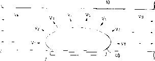
我们将在对图2(一个表示没有可动件的传统液体通道的结构示意图)和图3(表示本发明的图)进行比较的同时充分阐明这一原理。顺便提及,这里,向着喷口的压力传递方向用箭头VA表示,向上游侧(即,向公共液室)的压力传递方向用箭头VB表示。We will fully clarify this principle while comparing Fig. 2 (a schematic diagram showing the structure of a conventional liquid passage without movable parts) and Fig. 3 (a diagram showing the present invention). Incidentally, here, the direction of pressure transmission toward the ejection port is indicated by arrow VA, and the direction of pressure transmission to the upstream side (ie, to the common liquid chamber) is indicated by arrow VB.
如图2所示,在传统的喷液头中,没有控制因生成气泡40所引起的压力传递方向的控制机构。从而,气泡40的压力向各个方向传递。如垂直于气泡表面的箭头V1-V8所示,其中,压力传递方向V1-V4具有指向对液体喷射最有效的VA方向的分量,且压力传递方向V1-V4位于气泡的左半部靠近喷口,从而对液体喷射效率,液体喷射力及液体喷射速度有贡献。此外,由于压力传递方向V1指向喷射方向VA,所以它最有效;反之,压力传递方向V4指向喷射方向VA的分量最小。As shown in FIG. 2, in the conventional liquid discharge head, there is no control mechanism for controlling the direction of pressure transmission caused by the generation of air bubbles 40. As shown in FIG. Accordingly, the pressure of the air bubbles 40 is transmitted in various directions. As shown by the arrows V1-V8 perpendicular to the surface of the bubble, wherein the pressure transmission direction V1-V4 has a component pointing to the most effective VA direction for liquid injection, and the pressure transmission direction V1-V4 is located in the left half of the bubble near the nozzle, This contributes to the liquid ejection efficiency, liquid ejection force and liquid ejection velocity. Furthermore, since the pressure transfer direction V1 is directed to the injection direction VA, it is most effective; conversely, the pressure transfer direction V4 has the smallest component directed to the injection direction VA.
与此相反,在图3所示的本发明中,原来在图2中指向各个方向的原来传递方向V1-V4则通过可动件31的作用,全部向下游侧(即向着喷口)取向(即,将压力传递的各个方向均转变到下游侧方向VA),从而使气泡40的压力直接而有效地贡献于液体的喷射。与压力传递方向V1-V4类似,气泡的生长方向也指向下游侧(即,指向喷口),从而气泡在下游侧生长的比上游侧大。利用可动件31控制气泡40本身的生长方向和气泡40的压力传递方向可以提高喷射效率,喷射力和喷射速度。On the contrary, in the present invention shown in FIG. 3, the original transmission directions V1-V4 directed in various directions in FIG. , each direction of the pressure transfer is converted to the downstream side direction VA), so that the pressure of the
接下来将参照图4A至图4D及图5E至5H充分地描述根据图示实施例的喷液头的喷液操作。Next, the liquid discharge operation of the liquid discharge head according to the illustrated embodiment will be fully described with reference to FIGS. 4A to 4D and FIGS. 5E to 5H.
图4A表示在对发热元件2提供能量如电能之前的状态,即发热元件2发热之前的状态。重要的是,可动件31要设置在面对因发热元件2发热而将要形成的气泡的至少是下游侧的部分。就是说,可动件31延伸到至少是液体通道内发热元件区的中心的下游处(即,通过发热元件区中心并垂直于液体通道的长度方向延伸的一条直线的下游)。从而使得气泡的下游部分作用到可动件上。尤其是在本发明中,气泡被导向喷口,更需要可动件延伸到发热元件靠近喷口的一端。FIG. 4A shows the state before energy such as electric energy is supplied to the
图4B给出了对发热元件2提供电能使发热元件2发热,且利用发热元件提供的热量对气泡生成区的液体部分加热引起薄膜沸腾形成气泡40时的状态。FIG. 4B shows the state when electric energy is supplied to the
在这种情况下,由于气泡40的形成产生的压力使可动件31由第一位置运动或转移到第二位置,将气泡40的压力传递方向导向喷口18(图)。在这种情况下,液流不仅流向方向A(流向喷口18),也流向上游方向B。In this case, the
这里,如前所述,重要的是,可动件31的自由端32设置在下游侧,而图1中所示的支点33设置在上游侧(靠近公共液室)并且至少可动件的一部分要面对发热元件的下游部分(即,气泡的下游部分)。Here, as mentioned earlier, it is important that the
图4C表示气泡40进一步长大以及可动件31因气泡40的长大所产生的压力进一步发生位移时的状态。所生成的气泡40在下游侧比上游侧生长的更大,同时气泡的生长大大超出可动件31的第一位置(示于图4A)。此外,如果假定气泡在发热元件2周围的生长为第一波时,由于在可动件31的一端生成第二波,气泡40向上膨胀,从而使得气泡相对于喷口来说具有一个均匀的形状。当气泡40和气泡的压力向喷口18取向时,可动件31几乎不控制这种取向,从而可以有效地依据传递的压力的大小来控制压力的传递方向和气泡的生长方向。FIG. 4C shows the state when the
如前所述,由于可动件31是随着气泡40的长大逐步动作的,气泡40的压力传递方向被控制到这样一个方向,即,压力传递方向易于向该方向取向或者气泡的体积易于朝该方向(即,朝自由端)改变,从而气泡的生长方向均匀地朝喷口18取向。此外,液体向喷口18的流动速度VA(方向A)远大于液体向上游侧(方向B)流动的速度,从而可提高喷射效率。As mentioned above, since the
图4D表示气泡40即将和大气连通之前的状态。在图4D中,箭头(速度)VAU,VAC,VAL代表速度VA的分布,相对于中心速度VAC,较高处的速度分布用速度VAU表示,较低处的速度分布用速度VAL表示。关于当气泡40正在长大时的液体的速度,如前面提到的,由于气泡将长大成相对于喷口来说较为均匀的形状,所以靠近中心处的液体的中心速度VAC是均匀的,由于气泡是在这种状态下与大气连通的,所以液体会从喷口喷出而不会偏离喷射平面。这时,由于气泡仍然在液体通道内继续长大,液体通道10(图3)不会被完全阻塞或封闭,从而改善了对液体进行后续供应的补液性能。FIG. 4D shows the state of the
在图示的实施例中,决定生成的气泡40的形状的参数包括可动件31的材料和结构,以及一些传统的参数,如发热元件2产生的热量(由发热元件2的结构,构成发热元件的材料,驱动发热元件的驱动条件,发热元件的面积,安置发热元件2的基底的热容,及类似因素来决定),墨水的物理性质,记录头各部件的尺寸(例如喷口18和发热元件2之间的距离,喷口18和液体通道10的高度和宽度,及类似因素),以及类似的参数。适当的选择各个参数,气泡40可以按照所需要的条件与大气连通。In the illustrated embodiment, the parameters that determine the shape of the generated
当气泡40与大气连通时,气泡内部的压强基本上等于大气压或小于大气压是更为可取的。为了达到这样的条件,如图4D所示,气泡40可以在如下的条件下形成,即,对于发热元件2靠近喷口18的那一端与气泡40靠近喷口18的一端之间距离1a,和发热元件2远离喷口18的一端与气泡40远离喷口18的一端之间的距离1b的选择如下:即,1a/1b≥1。在图示的实施例中,各种参数的选择应满足上述条件。可动件31的结构和材料是决定气泡40形状的优选参数,在传统的决定方法中气泡的形状是根据如总热量,墨水的物理性质和记录头各部分的尺寸等决定的,与这种传统决定方法相比,则更容易形成满足条件1a/1b≥1的气泡。When the
图5E表示气泡刚刚和大气连通之后时的状态。如图所示,在图示的实施例中,由于设置了可动件31,在气泡40与大气连通的状态下,喷射液不会偏离喷口,且均匀平衡地脱离喷口,从而稳定了喷射方向。在这种情况下,分别在可动件31的上方和下方形成弯液面M1和M2。一般地,由于在可动件31的下方形成的生成气泡的区域比在可动件的上方存储待喷射液体的区域小,从而弯液面M2前进的速度MV2比上弯液面M1的前进速度MV1要快。但是,在图示的实施例中,由于有一个可动件31恢复到其原始状态的速度MV3叠加在弯液面M1的前进速度上,所以弯液面M1和M2的前进速度达到平衡,从而提高了补液速度。Fig. 5E shows the state immediately after the air bubble communicates with the atmosphere. As shown in the figure, in the illustrated embodiment, since the
此外,图5F中所示的被喷射的液体包括在气泡40与大气连通之前与气泡40接触的大部分液体。至于在气泡生成时液体的温度分布,则是与气泡40接触的液体部分温度最高。在图示的实施例中,由于这部分液体将要被喷射出去,所以可以抑制喷液头的温升。In addition, the ejected liquid shown in FIG. 5F includes most of the liquid that is in contact with the
此后,如图5F和5G所示,尽管可动件31的移动量逐渐减少直到可动件恢复到其初始位置,弯液面M1和M2仍旧保留在可动件自由端的上方和下方,直到恢复到如图5H所示的初始状态。可动件31恢复到其初始状态同时平衡弯液面M1,M2,从而进行补液。Thereafter, as shown in FIGS. 5F and 5G , although the moving amount of the
现在将说明上述的补液操作。The above-mentioned replenishment operation will now be described.
首先,将描述有关可动件31上部区域的补液操作。First, the liquid replenishment operation concerning the upper region of the
如图5E所示,当气泡40与大气连通时,由于大气压高于气泡40的内压,大气压进入喷口(喷嘴)。在这种情况下,喷嘴内的液体会被进入喷嘴内的大气压和将液体逼回上游侧的力(它是由于气泡的形成而在液体内产生并被气泡所抑制的)所阻滞。As shown in FIG. 5E, when the
大气进入喷嘴在图5E所示的状态下开始,大气压产生的作用力在图5E所示的状态成为最大。在这种情况下,可动件31的位移量也是最大的,从而阻止大气进入喷口,因此抑制了弯液面的延迟作用。此后,可动件31试图返回到图5H所示的状态。如上面提到的,弯液面M1,M2是分别在可动件31的上方和下方形成的。当可动件31逐渐向下移动返回其初始状态时,由于粘滞性的缘故,液体也与可动件31一起移动。由于液体是向补液的方向移动,所以在可动件31的上部区域的补液动作可以很快地实现。Atmospheric air enters the nozzle in the state shown in FIG. 5E, and the force due to the atmospheric pressure becomes maximum in the state shown in FIG. 5E. In this case, the amount of displacement of the
顺便提及,在可动件31下部区域的补液动作在气泡40生成时开始。在这种情况下,当可动件31逐渐向上移动时,由于液体也在补液方向移动,可动件31下部区域的补液动作可很快地实现。如上所述,在所示实施例中,关于可动件31上和下部的区域的补液动作可以很快地实现。此外,由于可动件31的存在,在补液过程中可以避免发生任何振动,从而可动件可以快速地返回其初始位置。Incidentally, the replenishment action in the lower region of the
此外,由于形成了两个弯液面,所以可避免弯液面生长的过大。在气泡的内压基本上等于大气压的最佳条件下,由于液体流向上游侧的动量变得很大,可以看出,无法顺畅地继续进行补液。但是,在图示的实施例中,因为形成了两个弯液面,从而防止了弯液面变得过大,所以,由于毛细现象,补液可以有效地进行。In addition, since two menisci are formed, excessive growth of the menisci can be avoided. Under the optimal condition where the internal pressure of the air bubble is substantially equal to the atmospheric pressure, since the momentum of the liquid flowing to the upstream side becomes large, it can be seen that the fluid replacement cannot be continued smoothly. However, in the illustrated embodiment, since two menisci are formed to prevent the menisci from becoming too large, liquid replenishment can be efficiently performed due to the capillary phenomenon.
下面将说明本发明的第二个实施例。Next, a second embodiment of the present invention will be described.
图6A,6D和7E,7G是本发明的第二个实施例的剖视图。6A, 6D and 7E, 7G are cross-sectional views of a second embodiment of the present invention.
本发明的第一个实施例是一种液体沿发热元件的纵向方向上喷射的类型(边缘斜槽型),而在第二个实施例中,则提供了这样一种类型(侧面斜槽型)的喷液头。其中,在与发热元件202的表面平行的一个平面内形成喷口,并且液体沿着与发热元件垂直的方向喷射。尽管没有标出,在这些图中,于图纸的右侧设置了一个公共液室,液体通道是弯曲的。在液体通道弯曲部的下方的基底201上形成发热元件202。此外,在发热元件202的左侧设置了一个壁以便将通过加热发热元件202生成的气泡的喷射力有效地导向喷口205。此外,在壁的下部有一锥形端面(向基底201张开)用以防止喷液后气泡滞留在液体中并使液体停留在发热元件上。通过设置这一锥形端面,当进行液体喷射操作时,液体总是停留在锥形端面的表面上,从而防止气泡的形成。The first embodiment of the present invention is a type in which liquid is sprayed in the longitudinal direction of the heating element (edge chute type), while in the second embodiment, such a type (side chute type) is provided ) of the spray head. Wherein, the nozzle is formed in a plane parallel to the surface of the
喷口205的截面积沿液体喷射方向逐渐减小,且该喷口与发热元件202面对放置。一个开/闭式的可动件231安放在喷口205和发热元件202之间。The cross-sectional area of the
图6A表示在能量,例如电能,加在发热元件202之前,也就是发热元件202发热之前的状态。同样,在本实施例中,可动件安放在一个面对将由发热元件202产生的气泡的至少是下游部分的位置上。就是说,可动件231要延伸到液体通道内发热元件202区域中心的至少是下游(即,穿过发热元件区域中心并垂直于液体通道长度方向延伸的一条直线的下游侧)处,从而使得气泡的下游部分作用到可动件231上。尤其是在本发明中,气泡是被可动件导向喷口的,所以更需要可动件延伸到发热元件更靠近喷口的一端。FIG. 6A shows the state before energy, such as electric energy, is applied to the
图6B表示当将发热元件202通电使发热元件202发热,并利用发热元件发出的热量将存储在气泡生成区的液体部分加热引起薄膜沸腾形成气泡时的状态。6B shows the state when the
在这种情况下,生成气泡240所引起的压力使可动件231运动,将气泡240的压力传递方向通过壁导向喷口205。In this case, the pressure caused by the generation of the air bubbles 240 moves the
如前所述,在这里重要的是,可动件231的自由端应设置在下游侧(靠近喷口205),可动件231的支点应设置在上游侧(靠近公共液室),并且至少可动件的一部分要面对发热元件的下游部分(即,气泡240的下游部分)。As mentioned earlier, what is important here is that the free end of the
图6C表示气泡240进一步长大,可动件231因气泡240长大引起的压力而进一步运动时的状态。生成的气泡240在下游侧比在上游侧生长的更大,且气泡生长得大大超出可动件231的初始位置(图6A所示)。当气泡240和气泡的压力被导向喷口205时,可动件231几乎不控制这种取向作用,从而依据所传递的压力大小,可有效地控制压力传递方向和气泡240的生长方向。FIG. 6C shows the state when the air bubble 240 grows further and the
如前所述,随着气泡240的生长,可动件231是逐渐运动的,气泡240的压力传递方向被控制在一个指向压力易于被传递的方向或者气泡的体积易于被改变(即指向自由端)的方向上,从而气泡的生长方向均匀地指向喷口205。此外,液体向喷口205(方向A)的流动速度VA远大于液体流向上游侧(方向B)的速度VB,从而可提高喷射效率。As previously mentioned, as the bubble 240 grows, the
图6D表示气泡240即将与大气连通之前的状态。这时,同样地,由于液体通道内的气泡240还在生长,所以液体通道并未被完全阻塞或封闭,从而改善了后续供液的补液性能。另外,由于在垂直于平板型可动件231表面的方向上,气泡240具有相对于喷口205对称的形状,所以稳定了被喷射的液体的方向。FIG. 6D shows the state of the air bubble 240 just before it communicates with the atmosphere. At this time, also, because the air bubbles 240 in the liquid channel are still growing, the liquid channel is not completely blocked or closed, thereby improving the performance of the subsequent liquid supply. In addition, since the air bubble 240 has a symmetrical shape with respect to the
在本实施例中,决定生成的气泡240的形状的参数包括发热元件202所产生的热能的量(与以下因素有关,即,发热元件204的结构,构成发热元件的材料,发热元件的面积,安放发热元件202的基底的热容,及类似因素),墨水的物理性质,记录头各部分的尺寸(如,喷口205与发热元件202之间的距离,喷口及液体通道的高度和宽度),及类似参数。通过适当地选择这些参数,气泡204可以在一个令人满意的条件下与大气连通。In the present embodiment, the parameters determining the shape of the generated bubble 240 include the amount of thermal energy produced by the heating element 202 (relevant to the following factors, namely, the structure of the heating element 204, the material forming the heating element, the area of the heating element, The heat capacity of the substrate on which the
图7E表示气泡240刚刚和大气连通后时的状态。如图所示,在图示的实施例中,由于设置了可动件231,在气泡240与大气连通的状态下,被喷射的液体相对于喷口不会偏移,而是均匀平衡地离开喷口,从而稳定了喷射方向。FIG. 7E shows the state immediately after the air bubble 240 communicates with the atmosphere. As shown in the figure, in the illustrated embodiment, since the
另外,图7F中所示的被喷射的液体中包含大部分在气泡240和大气连通前与气泡240相接触的液体。至于气泡240生成时液体的温度分布,则是与气泡240相接触的液体的温度最高。在图示的实施例中,由于正是这部分液体被喷射出去,从而抑制了喷液头的温升。In addition, the ejected liquid shown in FIG. 7F contains most of the liquid that is in contact with the air bubble 240 before the air bubble 240 communicates with the atmosphere. As for the temperature distribution of the liquid when the bubbles 240 are generated, the temperature of the liquid in contact with the bubbles 240 is the highest. In the illustrated embodiment, since it is this part of the liquid that is ejected, the temperature rise of the liquid discharge head is suppressed.
此后,尽管可动件231的弯液量逐渐减少直到可动件返回到图7G所示的初始位置,但仍然在可动件231自由端的上方和下方形成弯液面M1,M2,直到恢复到图7G所示的初始状态。可动件231返回到初始状态,它的运动使弯液面M1,M2平衡,从而进行补液。Thereafter, although the meniscus volume of the
第二实施例的补液操作与图4A至4D和图5E至5H所示的实施例的补液操作类似,因此补液操作可以很快地完成,同时,在补液过程中可以避免任何振动,从而可动件可很快的返回到其初始位置。The liquid replenishment operation of the second embodiment is similar to that of the embodiment shown in Figures 4A to 4D and Figures 5E to 5H, so the liquid replenishment operation can be completed quickly, and at the same time, any vibration can be avoided during the liquid replenishment process, so that the movable The parts can be quickly returned to their original position.
下面将说明本发明的第三个实施例。图8A至8D和图9E至9G是表示根据本发明的第二实施例的喷液操作的剖视图。Next, a third embodiment of the present invention will be described. 8A to 8D and FIGS. 9E to 9G are sectional views showing the liquid ejection operation according to the second embodiment of the present invention.
第三个实施例与第二个实施例类似,所不同的是,在第二个实施例中,用于防止液体喷射后气泡滞留于液体中的锥形端部表面是向基底201张口的,而在第三个实施例中,这种锥形端部表面则是向基底201收口的。The third embodiment is similar to the second embodiment, the difference is that in the second embodiment, the surface of the tapered end for preventing the air bubbles from remaining in the liquid after the liquid is sprayed is open to the
由于第三个实施例的喷液操作基本上和第二个实施例是一样的,所以将不做详细说明。Since the liquid ejection operation of the third embodiment is basically the same as that of the second embodiment, no detailed description will be given.
在图示的实施例中,通过设置这种锥形端部表面,在可动件返回其初始状态的过程中,由于气泡和大气的连通而进入液体通道的大气被有效地导向喷口205,从而,进入的大气被从喷口205排出,在可动件下方的区域(第二液体通道)中不残留任何气泡,并且同时提高了补液速度,从而允许高速操作。即使是液体内压缩有任何起泡的气体,由于这种起泡的气体通过可动件231的运动和壁的锥形端部表面的作用被从气泡生成区排出,因此气泡形成和液体的喷射效率仍然是稳定的。In the illustrated embodiment, by providing such a tapered end surface, during the return of the movable member to its original state, the atmosphere entering the liquid passage due to the communication of the air bubbles and the atmosphere is effectively guided to the
下面将说明本发明的第四个实施例。图10是表示第四个实施例的特性的剖视图。Next, a fourth embodiment of the present invention will be described. Fig. 10 is a sectional view showing the characteristics of the fourth embodiment.
根据第四个实施例的一个喷液头包括,一个基底801,其上设有为使液体内生成气泡提供热能的发热元件802,多个第二气泡液通道804安置在该基底上,多个第一液体通道803直接与各喷口810连通。A liquid discharge head according to the fourth embodiment includes a base 801 on which a
由具有弹性的材料如金属制成的分隔壁805设置在第一液体通道803和第二液体通道804之间,从而将第一液体通道803中的喷射液体与第二液体通道804中的气泡液隔离开。A
设置在发热元件802上方的凸出区(以后称作“喷射生成区”。图10中α区和一个气泡生成区β)的分隔壁的部分,由狭缝808限定,作为一个在靠近喷口侧有一个自由端(液流方向的下游侧),在靠公共液室(811,812)侧有一个支点的悬臂可动件806。由于可动件806与气泡生成区β面对设置,如第一个实施例中那样,所以由气泡液中产生的气泡将可动件向第一液体通道803(即,面向箭头所示的方向)打开。The portion of the partition wall of the protruding area (hereinafter referred to as "jet generating area"; α area and a bubble generating area β in FIG. 10) provided above the
一个用于防止在第二液体通道804中的气泡液生成逆波的发热体809具有一个用于生成消除逆波的气泡的加热丝(第二发热元件)。由图形蚀刻法形成的限定凹槽的阶梯部分置于加热丝809和发热元件802之间,而加热丝809则设置在一个向喷口倾斜的倾斜表面上。A
在图示的实施例中,在喷液操作中产生的逆波当中,在第一喷射液体通道803中产生的逆波被可动件806的运动消除,而在第二气泡液通道804中产生的逆波被加热丝809产生的气泡消除。In the illustrated embodiment, among the reverse waves generated in the liquid ejection operation, the reverse wave generated in the first
人们发现,通过对应于发热元件802进行的液体喷射,在一个预先选定的时机加热加热丝809以生成气泡,可以达到足够的防止逆波的效果。此外,由于凹槽位于加热丝809和发热元件802之间,所以气泡液可以十分有效地被存储于凹槽内的气泡液所补充。It has been found that by heating the
顺便提及,供应到第一液体通道的喷射液和供应到第二液体通道内的气泡液分别来自公共液室811,812。喷射液和气泡液可以是同一种液体。在这种情况下,可设置一个单一的公共液室。Incidentally, the ejection liquid supplied to the first liquid passage and the bubble liquid supplied into the second liquid passage come from the
下面说明本发明的第五个实施例。A fifth embodiment of the present invention will be described below.
在第五实施例中,第二液体通道804中发热元件802前部的一个区域(图10中的交叉影线)被切除以避免第二液体通道中的前向功率损失。采用这种结构可进一步提高喷射效率并获得更高质量的图象。In the fifth embodiment, an area in the second
顺便提及,我们在第一实施例中曾阐明过边缘斜槽型喷液头,而在第四和第五实施例中则应注意到,第四和第五实施例适用于侧面斜槽型喷液头,如在第二和第三实施例中那样。Incidentally, we have explained the edge chute type liquid discharge head in the first embodiment, but in the fourth and fifth embodiments, it should be noted that the fourth and fifth embodiments are applicable to the side chute type. Liquid discharge head, as in the second and third embodiments.
如上面提到的在通道生成气泡来实现喷液操纵的那些实施例中,重要的是在液体喷射后气泡不滞流在喷嘴内。如果有一部分气泡滞留在气泡生成区,则气泡的生成变得不稳定,造成不稳定的液体喷射。另一方面,如果气泡滞留在喷射区,则被喷射的液体变得不平衡,从而防碍了稳定的记录。在图6A到6D,7E到7G,8A到8D和9E到9G所示的第二和第三实施例中,通过设置锥形端部表面避免了对液体的阻滞,同时也可通过恰当的选择发热元件的驱动状态来避免气泡的滞留。这种驱动状态可以是稍稍移动可动件,以便在液体喷射后稳定可动件周围(特别是在可动件下方)的液体的状态。将这种驱动状态和正常的驱动状态相结合,可以实现稳定的液体喷射。As mentioned above, in those embodiments where the air bubbles are generated in the channel to realize the liquid ejection manipulation, it is important that the air bubbles do not stagnate in the nozzle after the liquid ejection. If a part of the bubbles stays in the bubble generation area, the generation of the bubbles becomes unstable, resulting in unstable liquid ejection. On the other hand, if air bubbles remain in the ejection area, the ejected liquid becomes unbalanced, preventing stable recording. In the second and third embodiments shown in Figures 6A to 6D, 7E to 7G, 8A to 8D and 9E to 9G, stagnation of liquid is avoided by providing tapered end surfaces, while also being possible by appropriate The driving state of the heating element is chosen to avoid the trapping of air bubbles. This driving state may be a state of slightly moving the movable member in order to stabilize the state of the liquid around the movable member (especially below the movable member) after the liquid is ejected. Combining this drive state with the normal drive state enables stable liquid ejection.
假定用于喷射液体的正常驱动状态为A,用于在液体喷射后稳定可动件周围的液体而将可动件稍稍移动的驱动状态为驱动状态B,下面将阐述根据本发明的喷射方法。Assuming that the normal driving state for ejecting liquid is A, and the driving state for stabilizing the liquid around the movable member after liquid ejection and slightly moving the movable member is driving state B, the ejection method according to the present invention will be explained below.
图11是一个表示采用上述两种驱动状态相结合的喷液方法的流程图。当喷液操作实施(喷液步骤开始)时,首先在驱动状态A(步骤S701)实施驱动。因而,如对上述各实施例已经阐述过的那样,可动件被移动(步骤S702),并实行补液(步骤S703)。此后,在驱动状态B下进行驱动,从而排出液体中不需要的气泡(步骤S705)。然后喷射步骤结束。Fig. 11 is a flow chart showing a liquid discharge method using a combination of the above two drive states. When the liquid ejection operation is carried out (the liquid ejection step starts), the driving is first performed in the driving state A (step S701). Therefore, as has been explained for the above-mentioned embodiments, the movable member is moved (step S702), and liquid replenishment is performed (step S703). Thereafter, driving is performed in the driving state B, thereby discharging unnecessary air bubbles in the liquid (step S705). Then the spraying step ends.
在液体喷射过程中通过做为一系列的连续操作完成上述步骤,可以防止气泡被滞留在液体内而实现良好的记录。By performing the above steps as a series of continuous operations during liquid ejection, good recording can be achieved by preventing air bubbles from being trapped in the liquid.
或者换一个方式,如图21所示,可以在发热元件21的下游侧设置一个用于生成对液体喷射不做贡献的气泡的小发热体(第二发热元件)902,并通过使这个不对喷液做贡献的气泡重复生成和消失,可动件可产生振动,从而通过止回阀效应将残余气泡从气泡生成区排放出去。Or change another way, as shown in FIG. 21, a small heating element (second heating element) 902 for generating bubbles that do not contribute to liquid spraying can be provided on the downstream side of the
此外通过设置两个可动件使得上面的可动件的自由端安放在下面的可动件自由端的上游侧,如图22a至22D所示,可加速可动件31从可动件31的支点侧的返回动作,从而可动件31将弯液面向下游侧推进,所以对气泡液的补液进行地更快,因而将残余的气泡从气泡生成区排出。In addition, by arranging two movable members so that the free end of the upper movable member is placed on the upstream side of the free end of the lower movable member, as shown in FIGS. The return action of the side, so that the
顺便提及,在图22A至22D中,给出了两个可动件,但也可以采用一个自由端比支点薄的单个可动件。Incidentally, in Figs. 22A to 22D, two movable members are shown, but a single movable member whose free end is thinner than the fulcrum may also be used.
<双液体通道型喷液头><Double liquid channel type liquid discharge head>
现在将说明一种可将两种不同液体很好的隔离地导入第一和第二公共液室的喷液头,它可减少零部件的数目并降低成本。A liquid discharge head capable of introducing two different liquids into the first and second common liquid chambers with good isolation, which can reduce the number of parts and cost, will now be described.
图12是一个表示边缘斜槽型的喷液头的剖面示意图。由于它进行液体喷射的基本结构与第一个实施例相同,所以与第一实施例相同的元件采用相同的标记数字,并不再加以详细说明。Fig. 12 is a schematic sectional view showing an edge chute type liquid discharge head. Since its basic structure for liquid ejection is the same as that of the first embodiment, the same reference numerals are used for the same components as those of the first embodiment, and no further detailed description will be given.
在图示的实施例中,一个开槽构件50包括一个具有喷口18的孔板51,许多沟槽构成许多第一液体通道14,和一个与许多第一液体通道14连通的并适于限定用于向第一液体通道提供液体(喷射液)的第一公共液室的凹槽。In the illustrated embodiment, a
通过将分隔壁30和开槽构件50的下部连结,可形成许多第一液体通道14。开槽构件50有一第一供液通道20由上部延伸入第一公共液室15。此外,开槽构件50有一第二供液通道21从上部经过分隔壁30延伸入第二公共液室17。By coupling the
如图12中箭头C所示,通过第一供液通道20和第一公共液室15将第一种液体(喷射液)供给第一液体通道14,并且,如图12中箭头D所示,通过第二供液通道21和第二公共液室17将第二种液体(气泡液)供给第二液体通道16。As shown by the arrow C in FIG. 12, the first liquid (spray liquid) is supplied to the
在图示的实施例中,虽然显示了第二供液通道21沿着与第一供液通道20平行的方向延伸的实例,但本发明不局限于这一实例,只要第二供液通道穿过设置在第一公共液室15外侧的分隔壁30延伸入第二公共液室17,则对第二供液通道的任何设计都可采用。In the illustrated embodiment, although an example in which the second
此外,第二供液通道21的尺寸(直径)的确定要考虑到第二种液体的供应量。第二供应液通道21的横截面形状不限于圆形,它还可以是矩形。In addition, the size (diameter) of the second
第二公共液室17可通过分隔壁30分隔开槽构件50而形成。例如,如图13(分解透视图)所示,通过在元件基底1上形成一个公共液室框架71和第二液体通道壁72,然后在基底1上安装分隔壁30和开槽构件50,这样便可构成第二公共液室17和第二液体通道16。The second
在图示实施例中,其上安装有许多用于产生热量、利用薄膜沸腾在气泡液中形成气泡的电/热转换器的元件基底1,被放置在由金属,例如铝,制成的支架70上。In the illustrated embodiment, the
在基底1上,有许多用以形成由第二液体通道壁72所确定的第二液体通道的槽,一个凹槽,构成与许多喷液通道连通并向喷液通道提供气泡液的第二公共液室,以及包含有可动件31的分隔壁30。On the
开槽构件50包括:与分隔壁30结合构成喷液通道(第一液体通道)14的槽,一个构成与喷液通道连通并向喷液通道提供喷射液的第一公共液室(公共喷射液腔室)15的凹槽,用以向第一公共液室提供喷射液的第一供液通道(喷射液供液通道)20,和用以向第二公共液室17提供气泡液的第二液体通道(气泡液供液通道)21。第二供液通道21与一个连通通道连接,该连通通道穿过位于第一公共液室15外侧的分隔壁30延伸入第二公共液室17,并且,借助这一连通通道,可将气泡液供给第二公共液室17,而不会与喷射液混合。The
就基底1、分隔壁30和开槽构件50之间的位置关系来说,可动件31与基底1的发热元件2对应设置,并且喷液通道14与可动件31对应的安排。另外,在图示实施例中,虽然对在开槽构件50中形成单一第二供液通道21的实例进行了阐述,但依据供液量,可以设置多个第二供液通道。另外,第二供液通道20,21的流动面积可按照与供液量成比例进行确定。通过按这种方式使流动面积最优化,可使构成开槽构件50的部分被制作得更为紧凑。In terms of the positional relationship between the
如上所述,根据本实施例因为用于向第二液体通道16提供第二种液体的第二供液通道21和用于向第一液体通道14提供第一种液体的第一供液通道20在同一个开槽构件(开槽顶板)上,所以,可减少部件的数目,制造步骤可以减少,并且可实现“降低成本”。As described above, according to the present embodiment, since the second
此外,因为向与第二液体通道16连通的第二公共液室提供液体,是借助贯穿分隔壁使第一和第二种液体相互分离的第二供液通道来实现的,所以分隔壁,开槽构件和基底之间的装配可由单一步骤完成。从而简化了制造工艺,提高了装配精度并达到良好的液体喷射。In addition, since the supply of liquid to the second common liquid chamber communicated with the
此外,因为第二种液体穿过分隔壁供给第二公共液室,所以必然可实现向第二液体通道提供第二种液体,并且,由于保证了充足的供液量,所以可实现稳定的液体喷射。In addition, since the second liquid is supplied to the second common liquid chamber through the partition wall, the supply of the second liquid to the second liquid passage can certainly be realized, and since a sufficient amount of liquid supply is ensured, stable liquid ejection can be realized. .
<喷射液和气泡液><Jet liquid and bubble liquid>
如上如上所述,在本发明中,因为喷液头具有上述可动件,所以能以比传统喷液头更高的喷射力和更高的喷射效率高速喷射液体。当气泡液和喷射液采用相同的液体时,只要该液体不会因发热元件产生的热而变质,由于热而从液体中沉淀出的物质不会在发热元件上沉积,可允许由于热在气化和冷凝之间进行可逆状态的变化,并且可防止使液体通道壁可动件和分隔壁变化,则各种液体均可选用。As described above, in the present invention, since the liquid discharge head has the above-mentioned movable member, it is possible to discharge liquid at high speed with higher discharge force and higher discharge efficiency than conventional liquid discharge heads. When the same liquid is used for the bubble liquid and the spray liquid, as long as the liquid does not deteriorate due to the heat generated by the heating element, the substance precipitated from the liquid due to the heat will not deposit on the heating element, and it is allowed to Various liquids can be selected if the reversible state change between condensing and condensing can be prevented, and the movable member and the partition wall of the liquid passage wall can be prevented from being changed.
在这些液体中,例如记录液,具有在传统气泡喷射设备中使用的传统成分的墨水都可被使用。Among these liquids, such as recording liquids, inks having conventional compositions used in conventional bubble jet devices can be used.
另一方面,当采用双通道型喷液头且喷射液与气泡液不同时,作为气泡液,可采用具有上述特性的液体。更具体地说,可采用下述液体:甲醇,乙醇,正丙醇,异丙醇,正己烷,正庚烷(n-heputane),正辛烷,甲苯,二甲苯,二氯甲烷,三氯甲烷,氟利昂TF,氟利昂BF,二乙醚,二噁烷,环己烷,乙酸甲酯,乙酸乙酯,丙酮,丁酮,水以及它们的混合物。On the other hand, when a two-channel type liquid discharge head is used and the ejection liquid is different from the bubble liquid, as the bubble liquid, a liquid having the above-mentioned characteristics can be used. More specifically, the following liquids can be used: methanol, ethanol, n-propanol, isopropanol, n-hexane, n-heptane, n-octane, toluene, xylene, methylene chloride, trichloro Methane, Freon TF, Freon BF, diethyl ether, dioxane, cyclohexane, methyl acetate, ethyl acetate, acetone, methyl ethyl ketone, water and their mixtures.
对于喷射液,各种液体都可使用,无需考虑其发泡能力和热特性。甚至具有低发泡能力的液体,容易受热变质的液体及高粘度的液体(传统技术难以喷射)也能够采用。As the spray liquid, various liquids can be used regardless of their foaming ability and thermal characteristics. Even liquids with low foaming ability, liquids that are easily deteriorated by heat, and liquids with high viscosity (difficult to eject with conventional techniques) can be used.
然而,如果喷射液的特性妨碍了液体的喷射,气泡的形成和/或可动件的操作,并且喷射液和气泡液之间发生反应,则这种喷射液不能采用。However, if the characteristics of the ejection liquid prevent ejection of the liquid, formation of bubbles and/or operation of the movable member, and a reaction occurs between the ejection liquid and the bubble liquid, such ejection liquid cannot be used.
对于记录喷射液,高粘度的墨水也可以使用。此外,具有低热阻的药液和香水也可作为喷射液。For the recording ejection liquid, high-viscosity ink can also be used. In addition, medicinal liquids and perfumes with low thermal resistance can also be used as spray liquids.
在本发明中,当记录液被同时用作喷射液和气泡液时,可使用具有下列成分的墨水。从而由于通过提高喷射力使喷射速度提高,所以提高了墨滴的喷射精度并获得了高品质的图象。 In the present invention, when the recording liquid is used as both the ejection liquid and the bubble liquid, an ink having the following composition can be used. Thus, since the ejection speed is increased by increasing the ejection force, the ejection precision of ink droplets is improved and a high-quality image is obtained.
此外,具有下列成分的气泡液和喷射液组合使用的液体,可用于记录。从而,不仅具有十个以上cps粘度的液体(在传统技术中难以喷射),甚至具有150cps的高粘度液体都可以有效地进行喷射,并获得高品质的图象。

(粘度55cp)喷射液3 聚乙二醇600 100wt%(Viscosity 55cp)
(粘度150cp)(Viscosity 150cp)
顺便提及,上述液体传统上认为是难以喷射的,因为喷射速度小,喷射方向不平直更加严重,墨滴的喷射精度更差,并且由于喷射不稳定使得喷射量不均匀,导致图象变劣。然而,在图示实施例中,通过采用气泡液,可产生稳定和适当的气泡。因此可提高液滴喷射精度,并使墨水喷射量稳定,从而大大改善了图象质量。Incidentally, the above-mentioned liquids have conventionally been considered difficult to eject because the ejection velocity is small, the ejection direction is more uneven, the ejection accuracy of the ink droplets is worse, and the ejection amount is uneven due to ejection instability, resulting in distorted images. inferior. However, in the illustrated embodiment, by using the bubble liquid, stable and proper bubbles can be generated. Therefore, the droplet ejection precision can be improved, and the ink ejection amount can be stabilized, thereby greatly improving the image quality.
<喷液头的制造><Manufacture of liquid ejection head>
下面,将对根据本发明的喷液头的制造方法进行阐述。Next, a method of manufacturing the liquid discharge head according to the present invention will be explained.
在图1所示喷液头的情况下,用以将可动件31固定到基底1上的基座34是通过图案成形干膜和类似方法形成的,并将可动件31粘接或焊接到基座34上。此后,将具有多个构成液体通道10的槽的开槽构件,喷口18,和构成公共液室13的凹槽部分以凹槽部分与可动件相对的方式连接到基底1上。In the case of the liquid discharge head shown in FIG. 1, the
下面,将阐述如图12所示的双通道型喷液头的制造方法。Next, a method of manufacturing the two-channel type liquid discharge head shown in Fig. 12 will be explained.
简明地说,第二液体通道16的壁形成于基底1之上,并且分隔壁30连接到基底上,然后,把具有构成液体通道14等的槽的开槽构件连接于其上。交替地,在形成第二液体通道16的壁之后,将连接有分隔壁30的开槽构件50连接到这些壁上。Briefly, the walls of the
现在,将对第二液体通道壁的制造方法进行充分地阐述。Now, the method of manufacturing the second liquid passage wall will be fully explained.
图14A至14E是用于阐明本发明喷液头制造方法的第一个实施例的剖视图。14A to 14E are sectional views for explaining the first embodiment of the method of manufacturing the liquid discharge head of the present invention.
在本实施例中,如图14A所示,利用与半导体制造工艺中所采用的设备相同的设备,在基底(有机硅树脂片)1上形成带有由硼化铪或氮化钽制成的发热元件的电/热转换器,此后,清理基底1的表面,以便改善在下一工艺或步骤中基底和光敏树脂之间的结合能力。此外,为了提高结合能力,需要在对基底1进行紫外线照射或臭氧照射后,将由酒精稀释到1wt%而获得的稀释的硅烷偶合剂(从日本Nippon Unica Co.,Ltd.获得的A189)离心涂敷到处理表面上。In the present embodiment, as shown in FIG. 14A , using the same equipment as that used in the semiconductor manufacturing process, a film with hafnium boride or tantalum nitride is formed on a substrate (silicone resin sheet) 1 . The electricity/heat converter of the heating element, thereafter, the surface of the
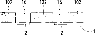
然后,在表面清理之后,如图14B所示,将对紫外线敏感的树脂薄膜DF(Dry Film Odel SY-318(商标),可由东京Ohka Co.,Ltd.获得)涂敷到基底1上(其表面的紧密接触能力已经获得了改善)。Then, after surface cleaning, as shown in FIG. 14B , an ultraviolet-sensitive resin film DF (Dry Film Odel SY-318 (trademark), available from Tokyo Ohka Co., Ltd.) is coated on the substrate 1 (the The close contact ability of the surface has been improved).
然后,如图14C所示,在干膜DF上放制光掩模PM并通过光掩模PM用紫外线照射到将要做为第二液体通道壁而加以保留的干膜DF的部分。利用曝光设备(MPA-600可由日本Canon获得)实现这一曝光过程,曝光量约为600mJ/cm2。Then, as shown in FIG. 14C, a photomask PM is placed on the dry film DF and ultraviolet rays are irradiated through the photomask PM to the portion of the dry film DF to be left as the second liquid channel wall. This exposure process was carried out using exposure equipment (MPA-600 available from Canon, Japan) with an exposure amount of about 600 mJ/cm 2 .
然后,如图14D所示,利用由二甲苯和butyl selsolve acetate的混合液组成的显影液(BMRC-3可由东京Ohka Co.,Ltd.获得)对干膜DF进行显影,溶去未曝光的部分,从而形成做为第二液体通道16壁部的变硬部分。此外,通过开动一个氧化物等离子体灰化设备把滞留在基底1上的残余物清除,处理时间约为90秒钟。然后,再用曝光量为100mJ/cm2的紫外线于150℃的温度下照射两小时,从而将已曝光部分完全硬化。Then, as shown in FIG. 14D , the dry film DF is developed with a developer consisting of a mixture of xylene and butyl selsolve acetate (BMRC-3 can be obtained from Tokyo Ohka Co., Ltd.) to dissolve unexposed parts , thereby forming a hardened portion as a wall portion of the
通过分割这样处理过的有机硅片获得的许多加热板(基底)具有高精度的液体通道16。利用一个具有厚度为0.05mm的金刚石刀的切割机(AWD-4000,可由东京Seimitsu Co.,Ltd.获得)将有机硅片分割成加热板。分割或分开的加热板1利用一种粘合剂(SE4400,可由Toray Co.,Ltd.获得)固定在铝基板(支座)70上。然后,将一个预先已连接到铝基板70上的印刷线路板71通过直径为0.005mm的铝线(未画出)连接到加热板1上。Many heating plates (substrates) obtained by dividing the thus-treated silicone sheet have
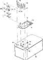
然后,如图14E所示,将开槽构件50和分隔壁30的组件对正并连接到加热板1上。就是说,包括分隔壁30在内的开槽构件50与加热板1通过顶盖弹簧(cap spring)78相互对正并连接,然后将墨水/气泡液供应件80与内插开槽构件和分隔壁组件的铝基板紧固连接。然后,将铝线之间的缝隙及开槽构件50,加热板1与墨水/气泡液供应件之间的缝隙,用有机硅密封胶(TSE399,可由Toshiba Silicone Co.,Ltd.获得)填充密封,从而制成喷液头。Then, as shown in FIG. 14E , the assembly of the grooved
通过按这种方法形成第二液体通道,可获得与加热板上的发热元件之间无位置偏差的高精度液体通道。特别是,通过一个预先的步骤事先将开槽构件50和分隔壁30安装到一起,可提高第一液体通道14和可动件31的位置精度。By forming the second liquid passage in this way, a high-precision liquid passage without positional deviation from the heating element on the heating plate can be obtained. In particular, the positional accuracy of the
通过采用这样的高精度制造方法,可使喷射性能稳定并改善图象质量。此外,因为基底可集中形成于有机硅片上,所以可允许大批量生产,从而可“降低成本”。By adopting such a high-precision manufacturing method, ejection performance can be stabilized and image quality can be improved. In addition, since the substrate can be collectively formed on the silicone wafer, mass production can be allowed, thereby enabling "cost reduction".
顺便提及,在图示实施例中,阐明了一个利用可被紫外线固化型的干膜以形成第二液体通道的例子,但也可用具有紫外光谱带(具体地说,靠近248nm的吸收带)的树脂,在涂布薄层之后,可将树脂固化,再用激光直接把对应于第二液体通道的部分除去。Incidentally, in the illustrated embodiment, an example of using a dry film of a UV-curable type to form the second liquid passage was explained, but it is also possible to use a dry film having an ultraviolet spectral band (specifically, an absorption band near 248 nm) After coating a thin layer of resin, the resin can be cured, and then the part corresponding to the second liquid channel can be directly removed by laser.
图15A至15D是表示本发明喷液头制造方法的第二个实施例的剖视图15A to 15D are sectional views showing a second embodiment of the method of manufacturing the liquid discharge head of the present invention
在本实施例中,如图15A所示,将厚度为15μm的抗蚀层101用图案成形法形成在SUS基板100上。将SUS基板100电镀,在SUS基板上形成15μm厚的镍层。至于电镀液,则使用磺酸镍,应力消除剂(“Zeorol:商标;可从World Metal Inc.获得),硼酸,防浸蚀液(NP-APS,从World Metal可以获得)和氯化镍。至于加在电镀层上的电场,则是一个电极与正极连接,用图案成形法形成的SUS基板1100与负极连接,并且选择电镀温度为50℃,电流密度为5cm2。In this embodiment, as shown in FIG. 15A, a resist
然后,如图15C所示,在电镀完成之后,对SUS基板100进行超声振荡,从SUS基板100上剥下镍层102,以便获得所需的第二液体通道。Then, as shown in FIG. 15C, after the electroplating is completed, the
另一方面,借助与半导体工艺中所使用的设备相同的设备,在有机硅树脂片上形成许多具有电/热转换器的加热板,然后,与第一实施例相似,利用切割机将有机硅树脂片分割成加热板。分割或分离出来的加热板1被固定到预先连接了印刷线路板71的铝基板70上,并且印刷线路板71与铝线(未画出)连接,从而完成电连接。如图15D所示,由预先的步骤获得的第二液体通道放置并固定到加热板1上。对于这种固定,与第一实施例相似,因为第二液体通道由带有分隔壁和顶盖弹簧的顶板紧固连接,所以这一固定可以在顶板的连接过程中不发生位置偏差的情况下完成。On the other hand, with the same equipment as that used in the semiconductor process, many heating plates with electric/thermal converters are formed on a silicone resin sheet, and then, similar to the first embodiment, the silicone resin is cut Slices are divided into heating plates. The divided or separated
在本实施例中,是利用可被紫外线固化的粘合剂(Amicon UV-300,可由Glace Japan Co.,Ltd.获得)并用紫外线照射设备用100mJ/cm2的曝光量照射3秒钟进行固定的。In this embodiment, it is fixed by using an ultraviolet-curable adhesive (Amicon UV-300, available from Glace Japan Co., Ltd.) and irradiating with an ultraviolet irradiation device with an exposure amount of 100 mJ/cm for 3 seconds of.
根据所述方法,可获得相对于发热元件无位置偏差的高精度第二液体通道16,并且,因为第二液体通道壁是由镍形成的,所以可得到具有对碱性液体有良好耐蚀性的高度可靠的喷液头。According to the method, a high-precision
图16A至16D是表示本发明喷液头的制造方法的第三个实施例的剖视图。16A to 16D are sectional views showing a third embodiment of the manufacturing method of the liquid discharge head of the present invention.
在本实施例中,如图16A所示,抗蚀层103涂敷在厚度为15μm具有校准孔100a或标记的SUS基板100的两表面上,至于抗蚀层采用可由Tokyo OhkaCo.,Ltd.获得的PMERP-AR900.In this embodiment, as shown in FIG. 16A, a resist layer 103 is coated on both surfaces of a
然后,如图16B所示,利用一个曝光设备(可从日本Canon Co.,Ltd.获得的MPA-600)依照基板100的校准孔100进行曝光,以便从用以形成第二液体通道的部分将抗蚀层除去。曝光是在800mJ/cm2的曝光量下进行的。Then, as shown in FIG. 16B, an exposure device (MPA-600 available from Canon Co., Ltd., Japan) is used to perform exposure according to the
然后,如图16C所示,把在两个表面上都有图案成形法形成的抗蚀层的SUS基板100浸入蚀刻液(氯化铁或氯化铜溶液),从而由抗蚀层103上蚀刻掉曝光的部分。然后,将抗蚀层剥离。Then, as shown in FIG. 16C, the
此后,如图16D所示,如以前的方法实施例中所述的那样,将刻蚀的SUS基板100对准并固定在发热板1上,从而组装成具有第二液体通道16的喷液头。Thereafter, as shown in FIG. 16D, the
根据图示的方法,可以得到相对于加热板没有位置偏差的高精度的第二液体通道,并且,由于液体通道壁是由SUS形成的,因此可以获得一个对碱性溶液具有良好耐蚀性的高可靠喷液头。According to the illustrated method, a high-precision second liquid channel with no positional deviation relative to the heating plate can be obtained, and, since the liquid channel wall is formed of SUS, it is possible to obtain a High reliability liquid spray head.
如前所述,根据图示的方法,由于预先在基板上为第二液体通道设置壁,所以电/热转换器和第二液体通道可以在分割之前同时在许多基板上形成,因此可以低成本得到许多喷液头。As mentioned before, according to the illustrated method, since the walls are preliminarily set on the substrate for the second liquid channel, the electric/thermal converter and the second liquid channel can be simultaneously formed on many substrates before being divided, so that low-cost Get lots of liquid jets.
另外,在用图示方法获得的喷液头中,由于发热元件和第二液体通道可以很高的精度相互定位,所以可有效地获得由发热元件产生的热量生产的气泡的应力,提高喷射效率。In addition, in the liquid discharge head obtained by the method shown in the figure, since the heating element and the second liquid passage can be positioned with each other with high precision, the stress of the air bubbles generated by the heat generated by the heating element can be effectively obtained, and the ejection efficiency can be improved. .
<喷液头卡盒><Liquid head cartridge>
下面将简单说明一个包含有上述喷液头的喷液头卡盒。A liquid discharge head cartridge containing the above liquid discharge head will be briefly explained below.
图17是一个包含上述喷液头的喷液头卡盒分解透视图。喷液头卡盒主要包括喷液头部分200和液体容器90。Fig. 17 is an exploded perspective view of a liquid discharge head cartridge containing the above liquid discharge head. The liquid ejection head cartridge mainly includes a liquid
喷液头部分200包括基底1,分隔壁30,开槽构件50,顶盖弹簧(capspring)78,供液件80和支座70。基底1包括许多并列排放的用于对气泡液加热的发热电阻体,和许多用于选择性地驱动发热电阻体的功能元件。气泡液通道在基底1与具有可动壁的分隔壁30之间形成,气泡液流经这些液体通道。通过将开槽构件50流经到分隔壁30上,形成喷射液体通道(未画出),喷射液体流经这些喷射液体通道。The liquid
顶盖弹簧(cap spring)78对开槽构件50施加一个向着基底1方向的加载力。通过这样一个加载力,基底1,分隔壁30和开槽构件50与后面将要描述的支座70有效地结合成一个整体。A cap spring (cap spring) 78 exerts a loading force toward the
支座70用于支承基底1,在支座70上设置一个与基底1连结并提供电信号的印刷线路板71,以及用于连结到喷液设备上的接触座72以实现卡座与设备之间的连通。The
液体容器90用来独立地容纳喷射液如墨水和用于生成气泡的气泡液。用于固定将液体容器连结到喷液头部分的连结件的定位部分94和用于固定连结件的固定轴95设置在液体容器90的外表面上。喷射液由液体容器90的喷射液供应通道92通过连结件的供应通道84被提供到供应件80的喷射液供应通道81,然后经过构件的液体供应通道83,71,21提供到带有公共液室。类似地,气泡液由液体容器90的气泡液供应通道93经连结件的供应通道提供到供应件80的气泡液供应通道,然后通过构件的液体供应通道84,71,21被提供到第二公共液室。The
在上述喷液头卡盒中,阐述了当气泡液与喷射液不同时可进行供液的供液系统和液体容器,而当喷射液和气泡液相同时,气泡液的供液通道则可不必与喷射液供液通道隔离,液体容器内可储存单一液体。In the liquid ejection head cartridge described above, the liquid supply system and the liquid container that can supply liquid when the bubble liquid and the spray liquid are different are described, and when the spray liquid and the bubble liquid are the same, the liquid supply channel of the bubble liquid can be unnecessary. Separated from the spray liquid supply channel, a single liquid can be stored in the liquid container.
顺便提及,当液体容器内的液体用完或耗尽时,可以灌注新液。为此在液体容器上应设置注液口。此外,液体容器可与喷液头部制成一个整体或者是可拆卸地安装在喷液头部分上。Incidentally, when the liquid in the liquid container is used up or exhausted, it can be filled with new liquid. For this reason, a liquid injection port should be provided on the liquid container. In addition, the liquid container may be integrally formed with the liquid discharge head or detachably attached to the liquid discharge head portion.
<喷液设备><Liquid spray equipment>
图18示意地给出了安装有上述喷液头的喷液设备。在这个例子中,将特别对用墨水做喷射液的喷液记录设备IJRA做为喷液设备进行说明。可拆卸地装有储存墨水的液体容器90和喷液头部分200的卡盒安装在设备的卡盒HC上。卡盒可沿着由记录介质传送装置传送的记录介质150的横向方向(a,b方向)往复运动。Fig. 18 schematically shows a liquid discharge apparatus equipped with the above liquid discharge head. In this example, a liquid jet recording apparatus IJRA using ink as the ejection liquid will be described specifically as the liquid ejection apparatus. A cartridge detachably housing the
当由驱动信号提供机构(未画出)向卡盒上的喷液构件提供一个驱动信号时,根据该驱动信号,记录液体从喷液头部分喷向记录介质。When a drive signal is supplied from a drive signal supply mechanism (not shown) to the liquid ejection member on the cartridge, the recording liquid is ejected from the liquid ejection head portion to the recording medium according to the drive signal.
此外,在图示实施例的喷液设备中,设有一个用于驱动记录介质传送机构和卡盒的电机(驱动源)111,用于将驱动源的驱动力传递到卡盒的齿轮112,113和一个卡盒轴85。利用该记录设备和喷液方法(在记录设备中实行)将液体喷射到各种类型的记录介质上,可在记录介质上记录令人满意的图象。Furthermore, in the liquid ejecting apparatus of the illustrated embodiment, there is provided a motor (drive source) 111 for driving the recording medium conveying mechanism and the cartridge, a
图19是使用本发明的喷液头进行喷墨记录的整个设备的框图。Fig. 19 is a block diagram of an entire apparatus for ink jet recording using the liquid jet head of the present invention.
在该记录设备中,主计算机300接收记录信息做为控制信号。记录信息暂时寄存在设备的输入/输出接口301,同时,在设备中转换成一个可处理的数据。该数据输入到同时也做为喷液头驱动信号提供机构的中央处理器(CPU)302。中央处理器302根据存储在只读存储器(ROM)303中的控制程序处理输入的数据,利用外设部件如随机存储器(RAM)304,将输入的数据转换成打印数据(图象数据)。In this recording apparatus, a host computer 300 receives recording information as a control signal. The record information is temporarily stored in the input/output interface 301 of the device, and at the same time, converted into a processable data in the device. This data is input to a central processing unit (CPU) 302 which also serves as a head driving signal supply mechanism. The CPU 302 processes input data according to a control program stored in a read only memory (ROM) 303, and converts the input data into print data (image data) using peripheral components such as a random access memory (RAM) 304.
此外,中央处理器302产生一个驱动数据用以驱动电机306使记录介质和喷液头200与图象数据同步移动以便将图象数据记录在记录介质的适当位置上。图象数据和电机驱动数据分别经过喷液头驱动器307和电机驱动器305传输到喷液头200和驱动电机306,从而在一控制的时刻驱动喷液头和电机形成图象。In addition, the central processing unit 302 generates a drive data for driving the motor 306 to move the recording medium and the
适用于上述记录设备并可接受如墨水等液体的记录介质可以是各种纸张,OHP板,用做致密盘或装饰板的塑料板,织物,铝、铜或类似物制成的金属材料,皮革,猪皮,人造革,木材,木板,竹板,陶瓷板如瓷砖,或者三维物品如海绵。The recording medium suitable for the above-mentioned recording device and accepting liquid such as ink may be various papers, OHP boards, plastic boards used as compact disks or decorative boards, fabrics, metal materials made of aluminum, copper or the like, leather , pigskin, artificial leather, wood, wooden boards, bamboo boards, ceramic boards such as tiles, or three-dimensional objects such as sponges.
此外,该打印设备可包括一个用于在各种纸张或一个OHP板上进行打印记录的打印机,一个用于在塑料材料如致密盘上进行记录的塑料记录设备,一个用于在金属上进行记录的金属记录设备,一个用于在皮革上进行记录的皮革记录设备,一个用于在木材上进行记录的木材记录设备,一个用于在陶瓷材料上进行记录的陶瓷记录设备,一个用于在三维网状物如海绵上进行记录的记录设备和一个在织物上进行记录的印刷设备。In addition, the printing device may include a printer for recording on various papers or an OHP board, a plastic recording device for recording on plastic materials such as compact discs, and a recording device on metal a metal recording device, a leather recording device for recording on leather, a wood recording device for recording on wood, a ceramic recording device for recording on ceramic materials, and a A recording device for recording on a web such as a sponge and a printing device for recording on fabric.
此外,可根据记录介质的种类和记录条件对用于这些喷液记录设备中的喷射液体进行选择。Furthermore, the ejection liquid used in these liquid ejection recording apparatuses can be selected according to the kind of recording medium and recording conditions.
<记录系统><record system>
下面将阐述一个利用本发明的喷液头在记录介质上进行记录的喷墨记录系统的例子。An example of an ink jet recording system for recording on a recording medium using the liquid jet head of the present invention will be explained below.
图20是一个用以阐明采用本发明的喷液头201的喷墨记录系统的示意图。本实施例的喷液头是一个全行(full-line)型喷液头,它有许多沿记录介质150允许的记录宽度以360 dpi的间隔设置的喷口,四个分别对应于黄(Y)色,深红(M)色,深兰(C)色和黑(BK)色的喷液头沿X方向以预定的间隔由支座202紧固固定。Fig. 20 is a schematic diagram for explaining an ink jet recording system using the
由喷液头驱动器(驱动信号提供机构)307向喷液头之一提供信号,喷液头根据该信号被驱动。A signal is supplied from a head driver (drive signal supply mechanism) 307 to one of the liquid discharge heads, and the liquid discharge head is driven according to the signal.
四种颜色(Y,M,C,BK)的墨水分别由墨水容器204a-204d做为喷射液供给各喷液头。顺便提及,参考数字204e表示装有气泡液的气泡液容器,气泡液由气泡液容器提供给喷液头。Inks of four colors (Y, M, C, Bk) are supplied as ejection liquids from the
此外,在各喷液头下方设置含有墨水吸收材料如海绵的喷液头罩203a-203d,在非工作状态,用喷液头罩覆盖喷液头的喷口,以保护喷液头。参考数字206表示构成传送前面所述的各种记录介质的传送装置的传送带。传送带206安装在许多滚轮上,并由与驱动电机305连结的驱动轮驱动。In addition, head covers 203a to 203d containing ink absorbing materials such as sponges are provided below the respective heads, and the head covers are used to cover the nozzles of the heads in a non-operating state to protect the heads.
根据图示实施例的喷墨记录系统中,设有一个预处理装置251用于在记录开始前对记录介质进行预处理,并设置在记录介质传送路径的上游侧,还设有一个后续处理装置252用于对记录结束后记录介质进行后续处理,设置在记录介质传送路径的下游侧。In the inkjet recording system according to the illustrated embodiment, a
预处理和后续处理依据记录介质的种类和/或墨水的种类的不同而变化。例如对于金属,塑料或陶瓷制成的记录介质,做为预处理,利用紫外线和臭氧照射记录介质使记录介质表面活化,从而提高墨水对记录介质的粘着能力。此外,对于容易产生静电的记录介质(如塑料),由于静电的作用记录介质表面容易粘附污物,从而妨碍良好的记录。因此,对于这种记录介质则采用电离器件去静电,除去记录介质上的污物做为预处理。此外,当用织物做记录介质时,从防止墨渍并改善色彩性能的角度,做为预处理,可在织物中加进在碱性物质,水溶性物质,人造聚合物,水容性金属氯化物,尿素和chiourea等中选取的材料。预处理不局限于上述例子,也可包括将记录介质的温度调节到适于记录的温度。Preprocessing and postprocessing vary depending on the type of recording medium and/or the type of ink. For example, for recording media made of metal, plastic or ceramics, as a pretreatment, the recording medium is irradiated with ultraviolet rays and ozone to activate the surface of the recording medium, thereby improving the adhesion of the ink to the recording medium. In addition, for recording media (such as plastics) that are prone to static electricity, dirt is likely to adhere to the surface of the recording medium due to the effect of static electricity, thereby hindering good recording. Therefore, for this kind of recording medium, an ionization device is used to remove static electricity and remove dirt on the recording medium as a pretreatment. In addition, when using fabric as a recording medium, from the perspective of preventing ink stains and improving color performance, as a pretreatment, alkaline substances, water-soluble substances, artificial polymers, water-capacity metal chlorides can be added to the fabric. Compounds, urea and chiourea etc. selected materials. The pretreatment is not limited to the above examples, and may also include adjusting the temperature of the recording medium to a temperature suitable for recording.
另一方面,后续处理可包括对记录介质的热处理,利用紫外线照射以提高墨水固着力的固着处理及清除残留处理剂的清洁处理。On the other hand, the subsequent treatment may include heat treatment of the recording medium, fixation treatment for improving ink fixation by ultraviolet irradiation, and cleaning treatment for removing residual treatment agent.
顺便提及,在图示的实施例中,阐述了采用全行喷液头做为喷液头的例子,但本发明并不局限于这个实例,可以沿着记录介质的横向方向移动上述紧凑的喷液头完成记录工作。Incidentally, in the illustrated embodiment, an example in which a full line of liquid discharge heads is used as the liquid discharge head has been described, but the present invention is not limited to this example, and the above-mentioned compact The ejection head completes the recording work.
在上述各实施例中展示的本发明的特征如下:The feature of the present invention shown in above-mentioned each embodiment is as follows:
(1)通过设置可动件,当气泡与大气连通时,连通部分稳定地保持在被喷射的液体与液体通道内的液体之间,确保液体通道不被阻塞,从而达到稳定的液体喷射。(1) By arranging the movable member, when the air bubble communicates with the atmosphere, the communication part is stably kept between the liquid to be sprayed and the liquid in the liquid channel, ensuring that the liquid channel is not blocked, thereby achieving stable liquid injection.
(2)当气泡与大气连通时,最理想的是气泡的内压基本上等于或小于大气压。在这种条件下,由于喷口内气体向上的动量很大,所以弯液面变得很大。但是,可动件的存在阻止了弯液面的长大,从而可以快速进行补液。(2) When the air bubble communicates with the atmosphere, it is most desirable that the inner pressure of the air bubble is substantially equal to or lower than the atmospheric pressure. Under these conditions, the meniscus becomes very large due to the large upward momentum of the gas in the nozzle. However, the existence of the movable part prevents the meniscus from growing up, so that fluid rehydration can be carried out quickly.
(3)产生喷射能量的气泡的生长方向可由可动件控制,从而提高了在喷射方向上的加速度。(3) The growth direction of the bubbles generating the ejection energy can be controlled by the movable member, thereby increasing the acceleration in the ejection direction.
(4)最理想的是气泡的内压基本上等于或小于大气压。这种气泡可在如下的条件下形成,即,发热元件靠近喷口的一端与气泡靠近喷口的一端之间的距离1a,和发热元件远离喷口的一端与气泡远离喷口的一端之间的距离1b,有这样的关系1a/1b≥1。在本发明中,由于气泡的生长方向可由可动件控制,所以很容易形成满足上述条件的气泡。(4) It is most desirable that the inner pressure of the bubble is substantially equal to or lower than the atmospheric pressure. This bubble can be formed under the following conditions, that is, the distance 1a between the end of the heating element near the nozzle and the end of the bubble near the nozzle, and the distance 1b between the end of the heating element away from the nozzle and the end of the bubble away from the nozzle, There is such a relationship 1a/1b≥1. In the present invention, since the growth direction of the bubbles can be controlled by the movable member, it is easy to form the bubbles satisfying the above conditions.
顺便提及,在上述各实施例中,阐述了一个利用薄膜沸腾产生气泡的例子。但在本发明中,任何沸腾产生的气泡均可受到控制,并且,由于补液靠正压气泡和大气之间的连通获得改善,所以由任何沸腾产生气泡的控制均包括在本发明的范围内。Incidentally, in each of the above-mentioned embodiments, an example of generating bubbles by film boiling was explained. However, in the present invention, any bubbles generated by boiling can be controlled, and since rehydration is improved by the communication between the positive pressure bubbles and the atmosphere, the control of bubbles generated by any boiling is included in the scope of the present invention.
如前所述,在本发明中,通过采用可动件,气泡的生长方向被集中向可动件的自由端。从而气泡的生长相对于喷口的分布可以更加均匀。因此,根据本发明,喷射液滴的不均匀性可以降到最小,液体喷射方向更加均匀。As described above, in the present invention, by using the movable member, the growth direction of the air bubbles is concentrated toward the free end of the movable member. Thereby the growth of the bubbles can be more evenly distributed with respect to the orifice. Therefore, according to the present invention, the unevenness of ejected liquid droplets can be minimized, and the liquid ejected direction can be more uniform.
通过采用给予大气连通型喷液头上述各种优点的可动件,液体喷射效率,补液效率和喷液稳定性是可以相互兼容的(而在传统技术中它们是不能兼容的)。因此,液体喷射效率,补液效率和喷液稳定性中至少有一个或者它们的全部都可得到改善。此外,可以获得高质量的图象。By employing the movable member which imparts the above-mentioned various advantages to the atmosphere communication type liquid discharge head, the liquid ejection efficiency, the liquid replenishment efficiency and the liquid discharge stability can be compatible with each other (whereas they were not compatible in the conventional art). Therefore, at least one or all of the liquid ejection efficiency, liquid replenishment efficiency, and liquid ejection stability can be improved. In addition, high-quality images can be obtained.
另外,还可以有效地喷射高粘滞性的液体和容易形成沉积物的液体(这在传统喷液头中是不可能的),而获得高质量的图象。In addition, highly viscous liquids and liquids that tend to form deposits, which were impossible in conventional liquid discharge heads, can be efficiently ejected to obtain high-quality images.
Claims (29)
Applications Claiming Priority (2)
| Application Number | Priority Date | Filing Date | Title |
|---|---|---|---|
| JP15980696 | 1996-06-20 | ||
| JP159806/96 | 1996-06-20 |
Publications (2)
| Publication Number | Publication Date |
|---|---|
| CN1170664A true CN1170664A (en) | 1998-01-21 |
| CN1096946C CN1096946C (en) | 2002-12-25 |
Family
ID=15701670
Family Applications (1)
| Application Number | Title | Priority Date | Filing Date |
|---|---|---|---|
| CN97114931A Expired - Fee Related CN1096946C (en) | 1996-06-20 | 1997-06-18 | Method for discharging liquid by communicating bubble with atmosphere, and apparatus |
Country Status (6)
| Country | Link |
|---|---|
| US (2) | US6270200B1 (en) |
| EP (1) | EP0813967B1 (en) |
| CN (1) | CN1096946C (en) |
| AU (1) | AU2613297A (en) |
| CA (1) | CA2208153C (en) |
| DE (1) | DE69730379T2 (en) |
Families Citing this family (32)
| Publication number | Priority date | Publication date | Assignee | Title |
|---|---|---|---|---|
| JP3403008B2 (en) * | 1996-07-05 | 2003-05-06 | キヤノン株式会社 | Liquid ejection head, head cartridge and recording apparatus using the same |
| JP3413063B2 (en) | 1996-07-09 | 2003-06-03 | キヤノン株式会社 | Liquid discharge method and liquid discharge head |
| JP3652016B2 (en) | 1996-07-12 | 2005-05-25 | キヤノン株式会社 | Liquid discharge head and liquid discharge method |
| US6494563B2 (en) | 1997-12-25 | 2002-12-17 | Canon Kabushiki Kaisha | Ink jet element substrate and ink jet head that employs the substrate, and ink jet apparatus on which the head is mounted |
| JP3592101B2 (en) * | 1998-09-14 | 2004-11-24 | キヤノン株式会社 | Liquid discharge method, liquid discharge head, and liquid discharge device |
| JP3762172B2 (en) * | 1998-12-03 | 2006-04-05 | キヤノン株式会社 | LIQUID DISCHARGE HEAD, HEAD CARTRIDGE WITH LIQUID DISCHARGE HEAD, LIQUID DISCHARGE DEVICE, AND METHOD FOR PRODUCING THE LIQUID DISCHARGE HEAD |
| US6491834B1 (en) | 1998-12-03 | 2002-12-10 | Canon Kabushiki Kaisha | Method for manufacturing liquid discharge head, liquid discharge head, head cartridge, and liquid discharge recording apparatus |
| US6468437B1 (en) | 1998-12-03 | 2002-10-22 | Canon Kabushiki Kaisha | Method for producing liquid discharging head |
| SE516696C2 (en) * | 1999-12-23 | 2002-02-12 | Perstorp Flooring Ab | Process for producing surface elements comprising an upper decorative layer as well as surface elements produced according to the method |
| JP2002046272A (en) | 2000-07-31 | 2002-02-12 | Canon Inc | Liquid ejection head, liquid ejection device, and liquid ejection method |
| EP1177902A1 (en) | 2000-07-31 | 2002-02-06 | Canon Kabushiki Kaisha | Liquid discharge head, method for manufacturing liquid discharge head, head cartridge on which liquid discharge head is mounted, and liquid discharge apparatus |
| US6827416B2 (en) | 2000-09-04 | 2004-12-07 | Canon Kabushiki Kaisha | Liquid discharge head, liquid discharge apparatus, valve protection method of the same liquid discharge head and maintenance system |
| JP4708586B2 (en) * | 2001-03-02 | 2011-06-22 | キヤノン株式会社 | Liquid discharge head, liquid discharge method, and method of manufacturing liquid discharge head |
| US7625080B2 (en) * | 2004-06-18 | 2009-12-01 | Hewlett-Packard Development Company, L.P. | Air management in a fluid ejection device |
| JP2006175744A (en) * | 2004-12-22 | 2006-07-06 | Canon Inc | Recording apparatus and recording method |
| JP2006175743A (en) * | 2004-12-22 | 2006-07-06 | Canon Inc | Recording apparatus, ink mist collecting method, and recording method |
| JP2007230194A (en) * | 2006-03-03 | 2007-09-13 | Canon Finetech Inc | Ink-jet recording head and its manufacturing method |
| EP1892107B1 (en) * | 2006-08-25 | 2009-11-04 | Homag Holzbearbeitungssysteme AG | Apparatus for printing a pattern on workpieces |
| PL1839883T3 (en) | 2006-03-08 | 2017-08-31 | Homag Holzbearbeitungssysteme Ag | Method and device for printing on plate-like objects |
| US7914098B2 (en) * | 2006-11-07 | 2011-03-29 | Homag Holzbearbeitungssysteme Ag | Device for patterning workpieces |
| JP2008149601A (en) * | 2006-12-19 | 2008-07-03 | Canon Inc | Inkjet recording method |
| ES2402367T3 (en) * | 2006-12-20 | 2013-05-03 | Homag Holzbearbeitungssysteme Ag | Device and procedure for coating parts |
| DE502007002035D1 (en) | 2007-03-27 | 2009-12-31 | Homag Holzbearbeitungssysteme | Method for printing a three-dimensional container |
| PL1990204T3 (en) * | 2007-05-10 | 2016-04-29 | Homag Holzbearbeitungssysteme Ag | Process and device for coating a surface |
| US20080314513A1 (en) * | 2007-06-19 | 2008-12-25 | Achim Gauss | Device for imparting a pattern onto the surface of work pieces |
| US20090120249A1 (en) * | 2007-11-14 | 2009-05-14 | Achim Gauss | Device For Refining Workpieces |
| EP2474655A4 (en) | 2009-09-02 | 2015-04-29 | Mimaki Eng Kk | Inkjet printer and printing method |
| DE102013216113A1 (en) | 2013-08-14 | 2015-03-05 | Homag Holzbearbeitungssysteme Gmbh | coating unit |
| CN107097531B (en) * | 2017-04-24 | 2018-07-13 | 习水县西科电脑科技有限公司 | A kind of print cartridge |
| WO2020201227A1 (en) | 2019-04-03 | 2020-10-08 | Corvaglia Mould AG | Closure for container and method for operating said closure |
| CN111672729B (en) * | 2020-05-07 | 2022-07-08 | 中国船舶重工集团公司第七二五研究所 | Preparation method of inner wall coating of pipe fitting with inner diameter not less than 30mm |
| CH718827A2 (en) | 2022-11-07 | 2023-01-13 | Corvaglia Mould AG | Closure for a container and method for its manufacture |
Family Cites Families (22)
| Publication number | Priority date | Publication date | Assignee | Title |
|---|---|---|---|---|
| JPS50124189A (en) | 1974-03-15 | 1975-09-30 | ||
| CA1127227A (en) | 1977-10-03 | 1982-07-06 | Ichiro Endo | Liquid jet recording process and apparatus therefor |
| JPS56139970A (en) | 1980-04-01 | 1981-10-31 | Canon Inc | Formation of droplet |
| US4395719A (en) * | 1981-01-05 | 1983-07-26 | Exxon Research And Engineering Co. | Ink jet apparatus with a flexible piezoelectric member and method of operating same |
| JPS5842466A (en) * | 1981-09-08 | 1983-03-11 | Canon Inc | Liquid jet recording method |
| US4449135A (en) * | 1981-12-23 | 1984-05-15 | Ricoh Company, Ltd. | Ink ejection head |
| JPS59167268A (en) * | 1983-03-15 | 1984-09-20 | Nec Corp | Printing head |
| JPS61249768A (en) * | 1985-04-30 | 1986-11-06 | Olympus Optical Co Ltd | Ink jet recording apparatus |
| US4638337A (en) | 1985-08-02 | 1987-01-20 | Xerox Corporation | Thermal ink jet printhead |
| DE69034212T2 (en) * | 1989-08-05 | 2006-07-13 | Canon K.K. | Ink jet recording device and ink cartridge therefor |
| JP2883113B2 (en) * | 1989-08-24 | 1999-04-19 | 富士ゼロックス株式会社 | Inkjet print head |
| JPH03190746A (en) * | 1989-12-21 | 1991-08-20 | Canon Inc | Ink jet recording apparatus |
| DE69126996T2 (en) * | 1990-04-27 | 1998-02-19 | Canon Kk | Recording method and device |
| ATE215118T1 (en) * | 1990-09-29 | 2002-04-15 | Canon Kk | METHOD AND APPARATUS FOR INKJET RECORDING |
| JP2962880B2 (en) | 1991-07-10 | 1999-10-12 | キヤノン株式会社 | Liquid jet recording method, liquid jet recording head, and recording apparatus |
| JPH05124189A (en) * | 1991-11-01 | 1993-05-21 | Matsushita Electric Ind Co Ltd | Ink discharge device |
| EP0571127A2 (en) * | 1992-05-22 | 1993-11-24 | Hewlett-Packard Company | Monolithic thermal ink jet print head for phase-changing ink |
| US5278585A (en) * | 1992-05-28 | 1994-01-11 | Xerox Corporation | Ink jet printhead with ink flow directing valves |
| JPH06996A (en) * | 1992-06-19 | 1994-01-11 | Hitachi Koki Co Ltd | Droplet ejector |
| JP3190746B2 (en) | 1992-10-29 | 2001-07-23 | 株式会社トプコン | Laser pointer |
| DE19505465A1 (en) | 1994-02-18 | 1995-08-24 | Hitachi Koki Kk | Thermal ink-jet printer |
| US5821962A (en) * | 1995-06-02 | 1998-10-13 | Canon Kabushiki Kaisha | Liquid ejection apparatus and method |
-
1997
- 1997-06-18 CN CN97114931A patent/CN1096946C/en not_active Expired - Fee Related
- 1997-06-18 CA CA002208153A patent/CA2208153C/en not_active Expired - Fee Related
- 1997-06-19 EP EP97304301A patent/EP0813967B1/en not_active Expired - Lifetime
- 1997-06-19 US US08/879,278 patent/US6270200B1/en not_active Expired - Lifetime
- 1997-06-19 AU AU26132/97A patent/AU2613297A/en not_active Abandoned
- 1997-06-19 DE DE69730379T patent/DE69730379T2/en not_active Expired - Lifetime
-
2001
- 2001-01-26 US US09/769,437 patent/US6474791B2/en not_active Expired - Fee Related
Also Published As
| Publication number | Publication date |
|---|---|
| CA2208153A1 (en) | 1997-12-20 |
| US6474791B2 (en) | 2002-11-05 |
| EP0813967A3 (en) | 1998-11-11 |
| DE69730379T2 (en) | 2005-08-18 |
| US6270200B1 (en) | 2001-08-07 |
| CA2208153C (en) | 2002-07-16 |
| DE69730379D1 (en) | 2004-09-30 |
| US20020033865A1 (en) | 2002-03-21 |
| EP0813967A2 (en) | 1997-12-29 |
| EP0813967B1 (en) | 2004-08-25 |
| AU2613297A (en) | 1998-01-08 |
| CN1096946C (en) | 2002-12-25 |
Similar Documents
| Publication | Publication Date | Title |
|---|---|---|
| CN1096946C (en) | Method for discharging liquid by communicating bubble with atmosphere, and apparatus | |
| CN1070111C (en) | Liquid jet head, liquid jet device and liquid jet method | |
| CN1115249C (en) | Liquid spraying device and method thereof | |
| CN1105018C (en) | Liquid ejecting head, liquid ejecting device and liquid ejecting method | |
| CN1072116C (en) | Method for producing liquid ejecting head and liquid ejecting head obtained by same method | |
| CN1090089C (en) | Liquid ejecting head, liquid ejecting device and liquid ejecting method | |
| CN1177542A (en) | Liquid-jet head, recovering method and mfg. method therefor, and liquid-jetting apparatus using same | |
| CN1078536C (en) | Liquid jet head, liquid jet device and liquid jet method | |
| US6095640A (en) | Liquid discharge head, liquid discharge method, head cartridge and liquid discharge device | |
| CN1191932C (en) | Liquid jetting method, liquid jetting head, and method for mfg. jetting device and jetting head | |
| CN1150930A (en) | Liquid ejecting head, liquid ejecting device and liquid ejecting method | |
| JP3403009B2 (en) | Liquid discharge method involving displacement of movable member and bubble growth, liquid discharge head used for the discharge method, head cartridge, and liquid discharge apparatus using these | |
| CN1160193C (en) | Liquid discharge head and discharge device | |
| CN1106287C (en) | Ink-jet head and method | |
| CN1145304A (en) | Liquid injection method with moving parts | |
| CN1179383A (en) | Liquid discharging method accompanied by displacement of movable member, liquid jet head for implementing such method, and liquid jet apparatus for implementation thereof | |
| CN1157778A (en) | Liquid spraying method, liquid spraying head and liquid spraying equipment | |
| CN1082446C (en) | Liquid discharging method, liquid supplying method, liquid discharge head, liquid discharge head cartridge using such liquid discharge head, and liquid discharge apparatus | |
| CN1115248C (en) | Liquid ejecting method, liquid ejecting head, and head cartridge using same | |
| CN1087228C (en) | Liquid discharging method, liquid discharging head, liquid discharging apparatus, liquid container and head cartridge | |
| CN1118374C (en) | Liquid discharging method, liquid discharging head, and head cartridge and liquid discharging apparatus using said liquid discharging head | |
| CN1178167A (en) | Liquid ejection head, liquid ejection equipment and printing system | |
| CN1172014A (en) | Liquid discharge method and liquid discharge head, inkjet recording method, and head for inkjet recording method | |
| CN1091685C (en) | Method for discharge of liquid and liquid discharge head | |
| JP3584149B2 (en) | Liquid ejection method and recording apparatus for implementing the method |
Legal Events
| Date | Code | Title | Description |
|---|---|---|---|
| C10 | Entry into substantive examination | ||
| SE01 | Entry into force of request for substantive examination | ||
| C06 | Publication | ||
| PB01 | Publication | ||
| C14 | Grant of patent or utility model | ||
| GR01 | Patent grant | ||
| CF01 | Termination of patent right due to non-payment of annual fee |
Granted publication date: 20021225 Termination date: 20150618 |
|
| EXPY | Termination of patent right or utility model |