CN1174332A - Fault determination device for radar equipment - Google Patents
Fault determination device for radar equipment Download PDFInfo
- Publication number
- CN1174332A CN1174332A CN97110724A CN97110724A CN1174332A CN 1174332 A CN1174332 A CN 1174332A CN 97110724 A CN97110724 A CN 97110724A CN 97110724 A CN97110724 A CN 97110724A CN 1174332 A CN1174332 A CN 1174332A
- Authority
- CN
- China
- Prior art keywords
- signal
- fault
- frequency
- modulator
- modulation
- Prior art date
- Legal status (The legal status is an assumption and is not a legal conclusion. Google has not performed a legal analysis and makes no representation as to the accuracy of the status listed.)
- Granted
Links
Images


Classifications
-
- G—PHYSICS
- G01—MEASURING; TESTING
- G01S—RADIO DIRECTION-FINDING; RADIO NAVIGATION; DETERMINING DISTANCE OR VELOCITY BY USE OF RADIO WAVES; LOCATING OR PRESENCE-DETECTING BY USE OF THE REFLECTION OR RERADIATION OF RADIO WAVES; ANALOGOUS ARRANGEMENTS USING OTHER WAVES
- G01S7/00—Details of systems according to groups G01S13/00, G01S15/00, G01S17/00
- G01S7/02—Details of systems according to groups G01S13/00, G01S15/00, G01S17/00 of systems according to group G01S13/00
- G01S7/40—Means for monitoring or calibrating
- G01S7/4052—Means for monitoring or calibrating by simulation of echoes
- G01S7/4056—Means for monitoring or calibrating by simulation of echoes specially adapted to FMCW
-
- G—PHYSICS
- G01—MEASURING; TESTING
- G01S—RADIO DIRECTION-FINDING; RADIO NAVIGATION; DETERMINING DISTANCE OR VELOCITY BY USE OF RADIO WAVES; LOCATING OR PRESENCE-DETECTING BY USE OF THE REFLECTION OR RERADIATION OF RADIO WAVES; ANALOGOUS ARRANGEMENTS USING OTHER WAVES
- G01S13/00—Systems using the reflection or reradiation of radio waves, e.g. radar systems; Analogous systems using reflection or reradiation of waves whose nature or wavelength is irrelevant or unspecified
- G01S13/88—Radar or analogous systems specially adapted for specific applications
- G01S13/93—Radar or analogous systems specially adapted for specific applications for anti-collision purposes
-
- G—PHYSICS
- G01—MEASURING; TESTING
- G01S—RADIO DIRECTION-FINDING; RADIO NAVIGATION; DETERMINING DISTANCE OR VELOCITY BY USE OF RADIO WAVES; LOCATING OR PRESENCE-DETECTING BY USE OF THE REFLECTION OR RERADIATION OF RADIO WAVES; ANALOGOUS ARRANGEMENTS USING OTHER WAVES
- G01S13/00—Systems using the reflection or reradiation of radio waves, e.g. radar systems; Analogous systems using reflection or reradiation of waves whose nature or wavelength is irrelevant or unspecified
- G01S13/02—Systems using reflection of radio waves, e.g. primary radar systems; Analogous systems
- G01S13/06—Systems determining position data of a target
- G01S13/08—Systems for measuring distance only
- G01S13/32—Systems for measuring distance only using transmission of continuous waves, whether amplitude-, frequency-, or phase-modulated, or unmodulated
- G01S13/34—Systems for measuring distance only using transmission of continuous waves, whether amplitude-, frequency-, or phase-modulated, or unmodulated using transmission of continuous, frequency-modulated waves while heterodyning the received signal, or a signal derived therefrom, with a locally-generated signal related to the contemporaneously transmitted signal
- G01S13/345—Systems for measuring distance only using transmission of continuous waves, whether amplitude-, frequency-, or phase-modulated, or unmodulated using transmission of continuous, frequency-modulated waves while heterodyning the received signal, or a signal derived therefrom, with a locally-generated signal related to the contemporaneously transmitted signal using triangular modulation
-
- G—PHYSICS
- G01—MEASURING; TESTING
- G01S—RADIO DIRECTION-FINDING; RADIO NAVIGATION; DETERMINING DISTANCE OR VELOCITY BY USE OF RADIO WAVES; LOCATING OR PRESENCE-DETECTING BY USE OF THE REFLECTION OR RERADIATION OF RADIO WAVES; ANALOGOUS ARRANGEMENTS USING OTHER WAVES
- G01S13/00—Systems using the reflection or reradiation of radio waves, e.g. radar systems; Analogous systems using reflection or reradiation of waves whose nature or wavelength is irrelevant or unspecified
- G01S13/88—Radar or analogous systems specially adapted for specific applications
- G01S13/93—Radar or analogous systems specially adapted for specific applications for anti-collision purposes
- G01S13/931—Radar or analogous systems specially adapted for specific applications for anti-collision purposes of land vehicles
-
- G—PHYSICS
- G01—MEASURING; TESTING
- G01S—RADIO DIRECTION-FINDING; RADIO NAVIGATION; DETERMINING DISTANCE OR VELOCITY BY USE OF RADIO WAVES; LOCATING OR PRESENCE-DETECTING BY USE OF THE REFLECTION OR RERADIATION OF RADIO WAVES; ANALOGOUS ARRANGEMENTS USING OTHER WAVES
- G01S7/00—Details of systems according to groups G01S13/00, G01S15/00, G01S17/00
- G01S7/02—Details of systems according to groups G01S13/00, G01S15/00, G01S17/00 of systems according to group G01S13/00
- G01S7/40—Means for monitoring or calibrating
- G01S7/4052—Means for monitoring or calibrating by simulation of echoes
- G01S7/406—Means for monitoring or calibrating by simulation of echoes using internally generated reference signals, e.g. via delay line, via RF or IF signal injection or via integrated reference reflector or transponder
- G01S7/4069—Means for monitoring or calibrating by simulation of echoes using internally generated reference signals, e.g. via delay line, via RF or IF signal injection or via integrated reference reflector or transponder involving a RF signal injection
Landscapes
- Engineering & Computer Science (AREA)
- Radar, Positioning & Navigation (AREA)
- Remote Sensing (AREA)
- Physics & Mathematics (AREA)
- Computer Networks & Wireless Communication (AREA)
- General Physics & Mathematics (AREA)
- Signal Processing (AREA)
- Electromagnetism (AREA)
- Radar Systems Or Details Thereof (AREA)
Abstract
振荡器产生的高频信号受到调制信号产生器产生的调制信号的频率调制后由发射天线向外辐射。接收天线接收到的从目标物体反射的反射信号在变频器中用定向耦合器输出的本振信号变频后,由信号处理单元检测其中的距离和速度信息。为了检测故障,与振荡器连接的调制器对振荡器的输出进行调制。包括滤波器、检波电路和电压比较电路的检测单元对在调制器中产生的受调成分进行检测。信号处理单元根据检测到的受调成分确定是否发生了故障。
The high-frequency signal generated by the oscillator is frequency-modulated by the modulation signal generated by the modulation signal generator, and then radiated outward by the transmitting antenna. The reflected signal received by the receiving antenna reflected from the target object is converted by the local oscillator signal output by the directional coupler in the frequency converter, and the distance and speed information is detected by the signal processing unit. To detect faults, a modulator connected to the oscillator modulates the output of the oscillator. A detection unit including a filter, a detection circuit and a voltage comparison circuit detects the modulated component generated in the modulator. The signal processing unit determines whether a fault has occurred based on the detected modulated components.
Description
本发明涉及一种FM-CW(调频连续波)雷达设备,这种雷达设备发射用调制信号调制(FM调制)的高频信号,接收从目标返回的反射信号,以及利用从发送信号中分出的部分信号作为接收机本振信号对所接收的反射信号进行变换。具体地说,本发明与安装在车辆上通过计算与目标物体的相对速度和距离来防止撞车的FM-CM雷达设备有关。The present invention relates to an FM-CW (frequency modulated continuous wave) radar device which transmits a high frequency signal modulated (FM modulated) by a modulating signal, receives a reflected signal returned from a target, and utilizes Part of the signal is used as the local oscillator signal of the receiver to transform the received reflected signal. In particular, the present invention relates to an FM-CM radar device installed on a vehicle to prevent a collision by calculating a relative speed and distance to a target object.
近年来,随着道路上车辆的增加,诸如撞车之类的事故呈逐年上升的趋势。因此,在车辆上应该安装经济的诸如车辆监视系统之类的安全设备,以便预先得到可能要撞车的信息,减少撞车事故。In recent years, with the increase of vehicles on the road, accidents such as car crashes have been on the rise year by year. Therefore, economical safety equipment such as a vehicle monitoring system should be installed on the vehicle in order to obtain information about possible collisions in advance and reduce collisions.
迄今为止,FM-CW雷达系统(调频连续波雷达系统)一直是用来作为一种能测量与目标物体的相对速度和距离的雷达系统。这种雷达系统能够用一个简单的信号处理电路来测量相对速度和距离,能够非常经济地实现收发装置,因而这种系统已用作车辆防撞雷达系统。Hitherto, the FM-CW radar system (Frequency Modulation Continuous Wave Radar System) has been used as a radar system capable of measuring relative speed and distance to a target object. This radar system is capable of measuring relative speed and distance with a simple signal processing circuit, and can implement a transceiver very economically, so this system has been used as a vehicle collision avoidance radar system.
图1和2中示出了FM-CW雷达系统的工作原理。图3例示了一种常规的FM-CW雷达设备。下面将对这种FM-CW雷达系统的原理加以说明。The working principle of the FM-CW radar system is shown in Figures 1 and 2. Fig. 3 illustrates a conventional FM-CW radar device. The principle of this FM-CW radar system will be described below.
如图3所示,捱荡器2输出的振荡信号由调制信号产生器1产生的几百赫兹的锯齿波进行FM调制后从发射天线5发射出去。然后,接收天线6接收到的从目标物体反射的反射信号输入到诸如混频器之类的变频器7。变频器7,作为一个FM检测器,用振荡器2输出的FM调制波作为本机振荡信号对接收到的信号进行检测。结果,由于从目标物体反射的反射波与发射信号之间存在频移,形成差拍,如图1和2所示。这差拍的频率fb取决于雷达系统与目标物体之间的距离以及由于相对速度而引起多普勒频移,可以表示为(取决于距离的距离频率fr)±(取决于速度的速度频率fd)。因此,可以根据这频移来确定距离和相对速度。As shown in FIG. 3 , the oscillating signal output by the
对于fr和fd有着以下众所周知的方程For f r and f d have the following well-known equations
fr=(4ΔΩT/C)Rf r =(4ΔΩT/C)R
fd=(2f0/C)v (1)其中:ΔΩ为调频带宽,T为调制波周期,C为光速,R为离障碍物(目标物体)的距离,f0为发射信号的中心频率,v为与障碍物(目标物体)的相对速度。f d =(2f 0 /C)v (1) Among them: ΔΩ is the frequency modulation bandwidth, T is the modulation wave period, C is the speed of light, R is the distance from the obstacle (target object), and f 0 is the center frequency of the transmitted signal , v is the relative velocity with the obstacle (target object).
如果在车载雷达系统采用这种方法,由于测量距离最大为100m(米),而相对速度可能达到100km/h(千米/小时),因此为了得到足够高的距离测量精度,调制波周期应设为1×10-3s(秒)左右,而调制带宽应设为100MHg(兆赫)左右。此外,为了得到足够高的相对速度测量精度,应采用毫米波段作为发射频段。例如,在调制波周期为1.33×10-3s,调制带宽为75MHg,发射频率为60GHz的情况下,距离分辨力为1m,而速度分辨力为6.75km/h。If this method is used in the vehicle radar system, since the maximum measurement distance is 100m (meter), and the relative speed may reach 100km/h (kilometer/hour), in order to obtain a sufficiently high distance measurement accuracy, the modulation wave period should be set It is about 1×10 -3 s (second), and the modulation bandwidth should be set to about 100MHg (megahertz). In addition, in order to obtain a sufficiently high relative speed measurement accuracy, the millimeter wave band should be used as the transmitting frequency band. For example, when the modulation wave period is 1.33×10 -3 s, the modulation bandwidth is 75MHg, and the transmission frequency is 60GHz, the distance resolution is 1m, and the speed resolution is 6.75km/h.
作为一种检测按照常规FM-CW雷达配置的雷达系统的高频电路中的故障的方法,已经考虑了通过监测加到各高频电路的一些部件的电流或电压值来检测故障的方法。As a method of detecting a malfunction in a high-frequency circuit of a radar system configured as a conventional FM-CW radar, a method of detecting a malfunction by monitoring current or voltage values applied to some components of each high-frequency circuit has been considered.
然而,这种方法有一个问题。虽然这种方法通过对电流或电压值的监测能够检测出重大故障(如完全不能工作),但很难检测出由于电路特性变坏之类而引起的性能下降和工作不正常的情况,因为在这种情况下电流和电压值的变化量是相当小的。However, there is a problem with this approach. Although this method can detect major failures (such as complete inoperability) by monitoring current or voltage values, it is difficult to detect performance degradation and abnormal operation due to deterioration of circuit characteristics, because in In this case the variation of current and voltage values is quite small.
本发明的目的是提供一种能检测由于高频电路特性变坏而引起的性能降低和工作不正常的低价FM-CW雷达设备。SUMMARY OF THE INVENTION An object of the present invention is to provide a low-cost FM-CW radar apparatus capable of detecting performance degradation and abnormal operation due to deterioration of high-frequency circuit characteristics.
本发明的主要内容是为一种发射经调制信号调制的高频信号、接收从目标物体反射的反射信号、用从发射信号分出的信号作为接收机本振信号对所接收的反射信号进行变频的雷达设备配置故障确定装置。The main content of the present invention is to transmit a high-frequency signal modulated by a modulated signal, receive the reflected signal reflected from the target object, and use the signal separated from the transmitted signal as the local oscillator signal of the receiver to convert the frequency of the received reflected signal The radar equipment is equipped with a fault determination device.
本发明的故障确定装置包括一个对输入到接收系统电路的本振信号进行调制的调制器,一个检测在这个调制器中产生的频率分量的检测电路,以及一个根据检测电路检测到的频率分量确定是否有故障的故障确定电路。The fault determination device of the present invention includes a modulator for modulating a local oscillator signal input to a circuit of a receiving system, a detection circuit for detecting a frequency component generated in the modulator, and a determination circuit based on the frequency component detected by the detection circuit. Whether there is a faulty fault determination circuit.
按照本发明,可以检测出在雷达设备彻底不能工作前由于高频电路特性变坏而引起的工作不正常和性能下降的情况。According to the present invention, it is possible to detect abnormal operation and degradation of performance due to deterioration of high-frequency circuit characteristics before the radar apparatus completely fails to operate.
从以下结合附图的详细说明中可以更清楚地看到本发明的情况。在这些附图中:The invention can be seen more clearly from the following detailed description taken in conjunction with the accompanying drawings. In these drawings:
图1示出了FM-CW雷达设备的基本原理;Figure 1 shows the basic principle of FM-CW radar equipment;
图2示出了FM-CW雷达设备的基本原理;Figure 2 shows the basic principle of FM-CW radar equipment;
图3为常规FM-CW雷达设备的方框图;Fig. 3 is the block diagram of conventional FM-CW radar equipment;
图4为本发明第一实施例的原理方框图;Fig. 4 is a schematic block diagram of the first embodiment of the present invention;
图5为本发明第二实施例的原理方框图;Fig. 5 is a schematic block diagram of the second embodiment of the present invention;
图6为本发明第三实施例的原理方框图;Fig. 6 is a schematic block diagram of the third embodiment of the present invention;
图7为本发明第四实施例的原理方框图;Fig. 7 is a schematic block diagram of the fourth embodiment of the present invention;
图8为本发明第五实施例的原理方框图;Fig. 8 is a schematic block diagram of a fifth embodiment of the present invention;
图9为本发明第一优选实施例的方框图;Fig. 9 is a block diagram of the first preferred embodiment of the present invention;
图10为示出DSP(数字信号处理器)处理情况的操作流程图;FIG. 10 is an operation flowchart showing a DSP (Digital Signal Processor) processing situation;
图11为示出CPU(中央处理单元)处理情况的操作流程图;Fig. 11 is the operation flowchart showing CPU (Central Processing Unit) processing situation;
图12为本发明第二任选实施例的方框图;Figure 12 is a block diagram of a second optional embodiment of the present invention;
图13为本发明第三优选实施例的方框图;Fig. 13 is a block diagram of the third preferred embodiment of the present invention;
图14为本发明第四优选实施例的方框图;Fig. 14 is a block diagram of the fourth preferred embodiment of the present invention;
图15为本发明第五优选实施例的方框图;Fig. 15 is a block diagram of the fifth preferred embodiment of the present invention;
图16为本发明第六优选实施例的方框图;Fig. 16 is a block diagram of the sixth preferred embodiment of the present invention;
图17为本发明第七优选实施例的方框图;以及Fig. 17 is a block diagram of the seventh preferred embodiment of the present invention; and
图18为示出CPU对温度变化的确定逻辑的操作流程图。FIG. 18 is an operational flow diagram illustrating the CPU's determination logic for temperature changes.
下面将参照附图对本发明的各优选实施例进行详细说明。Preferred embodiments of the present invention will be described in detail below with reference to the accompanying drawings.
首先将说明各优选实施例的原理,然后再详细说明本发明的各优选实施例。The principle of each preferred embodiment will be described first, and then each preferred embodiment of the present invention will be described in detail.
图4为本发明第一实施例的方框图。Fig. 4 is a block diagram of a first embodiment of the present invention.
调制信号产生器1产生用于频率调制(FM调制)的锯齿波信号。
压控振荡器2产生在雷达系统输出的毫米波段中的受调信号。The voltage controlled
调制器3进行检测故障所需的调制。
空向耦合器4将压控振荡器2输出的信号分为两路,一路为送至发射天线5的发射信号,另一路为送至变频器7的本振信号。The
发射天线与有效地将压控振荡器2输出的调频信号辐射出去。The transmitting antenna effectively radiates the FM signal output by the voltage-controlled
接收天线6有效地对从目标物体反射的信号进行接收。The
变频器7将来自空向耦合器4的本振信号与接收天线6接收的目标物体反射信号进行混频,产生含有目标物体与雷达设备之间的相对速度和距离信息的信号分量。The
信号处理单元8从奕频器7输出的信号分量中检测相对速度和距离信息,向显示器9输出进行显示所需的数据。The
显示器9显示信号处理单元8输出的显示数据。The
滤波器10的带宽仅允许用来检测雷达设备高频电路系统工作情况的受调频率可以通过。The bandwidth of the
检波电路11将受调信号变换为直流信号送至电压比较电路12。The
电压比较电路12将在高频电路系统中检测到的信号的检测电平与一个预置的基准电平进行比较,如果检测电平低于基准电平,就向CPU(图中未示出)发送一个告警信号。
在上述的本发明第一实施例中,调制器3相当于权利要求1或2中所述的调制器。滤波器10、检波电路11和电压比较电路12相当于权利要求1或2中所述的检测电路,而信号处理单元8相当于权利要求1或2中所述的故障确定电路。In the first embodiment of the present invention described above, the
实现了上述本发明第一实施例,就能在雷达设备完全不能工作前检测出由于高频电路特性变坏而引起的性能下降和工作不正常的情况。By realizing the first embodiment of the present invention as described above, it is possible to detect performance degradation and abnormal operation due to deterioration of high-frequency circuit characteristics before the radar apparatus fails to operate at all.
图5为本发明第二实施例的方框图。Fig. 5 is a block diagram of a second embodiment of the present invention.
如图5所示,在这个本发明第二实施例的雷达设备中,在图4所示的本发明第一实施例的定向耦合器4与发射天线5之间加了一个发射信号输出衰减电路13。发射信号输出衰减电路13相当于权利要求3-5部所述的发射信号输出衰减电路。As shown in Figure 5, in the radar device of the second embodiment of the present invention, a transmission signal output attenuation circuit is added between the
实现了上述本发明第二实施例,在选择了故障确定模式时,可以使输出发射信号得到衰减,从而可以降低外界对雷达系统的影响。Realizing the above-mentioned second embodiment of the present invention, when the fault determination mode is selected, the output transmission signal can be attenuated, so that the influence of the outside world on the radar system can be reduced.
图6为本发明第三实施例的方框图。Fig. 6 is a block diagram of a third embodiment of the present invention.
在作为本发明第三实施例的这个雷达设备中,在图4所示本发明第一实施例的接收天线6与变频器7之间加了一个接收信号输入衰减电路14。接收信号输入衰减电路14相当于权利要求6-8中所述的接收信号输入衰减电路。In this radar apparatus as the third embodiment of the present invention, a received signal input attenuation circuit 14 is added between the receiving
实现了上述本发明第三实施例,在选择了故障确定模式时,可以使接收信号得到衰减,从而可以降低外界对雷达系统的影响。The above-mentioned third embodiment of the present invention is realized, and when the fault determination mode is selected, the received signal can be attenuated, thereby reducing the influence of the outside world on the radar system.
图7为本发明第四实施例的方框图。Fig. 7 is a block diagram of a fourth embodiment of the present invention.
在图7所示的与本发明第四实施例有关的这个雷达设备中,在图4所示本发明第一实施例的方向耦合器4与变频器7之间加了一个本振信号调制器15来代替调制器3。本振信号调制器15相当于权利要求9中所述的本振信号调制器。于是,在选择了故障确定模式时,本振信号就受到本振信号调制器15的调制。In the radar equipment related to the fourth embodiment of the present invention shown in FIG. 7, a local oscillator signal modulator is added between the
图8为本发明第五实施例的方框图。Fig. 8 is a block diagram of a fifth embodiment of the present invention.
在本发明第五实施例中,形成了一条反馈通路,使得从经定向耦合器4分路后的发射信号中再经定向耦合器16分出一路信号与来自定向耦合器17的所接收的反射信号混合。在这条反馈通路中加有一个反馈信号调制器18。这里,定向耦合器16和17相当于权利要求10中所述的反馈回路,而反馈信号调制器18相当于权利要求10中所述的反馈信号调制器。In the fifth embodiment of the present invention, a feedback path is formed, so that from the transmitted signal branched by the
如在以上本发明第一至第五实施例中所说明的那样,用于执行故障确定模式所用的信号的受调频率可以设置成与用来产生发射信号的频率调制的受调频率不同的频率。As explained above in the first to fifth embodiments of the present invention, the modulated frequency of the signal used to perform the fault determination mode can be set to a frequency different from the modulated frequency of the frequency modulation used to generate the transmission signal .
此外,在本发明第一至第五实施例中,可以采用调频或调相而不采用调幅来作为确定故障的一种信号调制方法。振幅调制例如可以通过改变放大器的增益或通断信号来实现。Furthermore, in the first to fifth embodiments of the present invention, frequency modulation or phase modulation may be used instead of amplitude modulation as a signal modulation method for determining a fault. Amplitude modulation can be achieved, for example, by varying the gain of an amplifier or switching the signal on and off.
下面将结合附图说明根据上述原理所提出的本发明优选实施例。Preferred embodiments of the present invention based on the above principles will be described below with reference to the accompanying drawings.
图9为本发明第一优选实施例的方框图。Fig. 9 is a block diagram of a first preferred embodiment of the present invention.
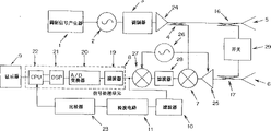
图9所示的FM-CW雷达设备包括作为发射系统的调制信号产生器1、压控振荡器2、调制器3、定向耦合器4和发射天线5,作为接收系统的接收天线6和变频器7,以及作为信号处理系统的信号处理单元8(包括滤波器19、A/O变换器20、DSP21和CPU22)、显示器9、滤波器10、检波电路11和比较器23。The FM-CW radar equipment shown in Fig. 9 comprises
这里,调制信号产生器1产生进行调频的锯齿波信号。压控振荡器2产生雷达输出的毫米波段调频信号。调制器3产生故障检测信号。定向耦合器4接收来自调制器3的毫米波信号,作为送至发射天线5和变频器7的本振信号。发射天线5有效地将定向耦合器4输出的信号辐射出去。接收天线6有效地对从目标物体反射的信号进行接收。变频器7将接收天线6所接收的信号与来自定向耦合器4的本振信号进行混频,产生含有目标物体与雷达设备之间的相对速度和距离信息的信号分量,并产生故障检测信号。信号处理单元8从变频器7输出的这些信号分量中检测出相对速度和距离信息,向显示器9输出必需的显示数据。在信号处理单元8中,滤波器19仅提取拍频分量(如图1和2所示)。A/D变换器20将滤波器19输出的模拟信号变换为数字信号。DSP21通过对A/D变换器20输出的数字信号进行FFT(快速的傅立叶变换)分析提取拍频分量,根据前面所列的方程(1)计算出距离和相对速度。CPU22通过监测比较器23的输出进行故障检测处理,并且为显示器9进行数据显示处理。然后,显示器9显示信号处理单元8输出的显示数据。滤波器10从变频器7输出的那些信号分量中滤出故障检测所需的信号分量。检波电路11将滤波器10输出的交流信号变换为直流信号。比较器23将检波电路11输出的故障检测信号与预先设定的基准信号进行比较。Here, the
包括上述各部件的FM-CW雷达设备的工作情况如下。The operation of the FM-CW radar apparatus including the above-mentioned components is as follows.
调制信号产生器1产生的锯齿波加到压控振荡器2,以便产生调频波。所产生的调频波的输出波形为
然后,这个信号受到调制器3的调制。如果调制方法是AM调制,则调制器3的输出信号为
这个信号从定向耦合器4加到变频器7,作为本振信号。为了说明简明起见,假设没有从目标物体反射的反射波,若式(3)所示的信号是经变频器7平方律检测的,则变频器7的输出信号可表示为:
信号Sdet经检波电路11变换为直流信号后,由比较器23用基准电压加以比较,于是就能检测是否出现故障情况。这里,基准电压设置为雷达设备工作正常时所产生的直流信号的值加上考虑季节和温度的改变量。就实际例子而言,如果比较器23发现检波电路11输出的直流信号的电压低于基准电压,CPU22就确定雷达工作不正常。这样,例如当变频器7中变频损耗增大时,由于变频器7输出的信号的绝对值总体减小,因此检波电路11输出的直流信号的电压下降。此外,如果调制信号产生器1的输出电压下降,那么由于从定向耦合器4输入变频器7的信号的输入电平下降,检波电路11输出的直流信号的电压也要下降。因此,检波电路11输出的直流信号的电压下降说明在高频电路中,无论是在雷达设备的接收部分还是发射部分,信号灵敏度已经降低。这就表明车辆前方最大检测距离已经减小。车辆前方最大检测距离减小意味着例如原来在车辆前方距离成为100m时告警的现在改变为在车辆前方距离成为60m时才告警。After the signal Sdet is converted into a DC signal by the
图10为示出DSP处理情况的操作流程图。DSP21对A/D变换器20输出的数字信号进行FFT(快速傅立叶变换)分析(图10的步骤30),识别出FFT频率输出的尖峰频率(步骤31)。然后,DSP21通过计算尖峰频率电平门限值(步骤32)限制所要使用的尖峰的个数(步骤33)。接着,DSP21估计可用尖峰的个数(步骤34),从提取的尖峰分量中滤除噪声分量(步骤35),最后从剩下的这些尖峰中提取两个拍频分量fb=(取决于距离的距离频率fr)±(取决于速度的速度频率fd),再根据前面所列的方程(1)解出距离R和相对速度v(步骤36),处理过程结束。Fig. 10 is an operational flow chart showing the state of DSP processing. The
图11为示出CPU22中处理情况的操作流程图。CPU22设置当前模式为故障检测模式(图11的步骤40)。可以将设置当前模式为故障检测模式的时间定在车辆发动机刚起动时或雷达设备刚接通时,然后,CPU22监测比较器23的输出电压(步骤41),通过确定比较器23的输出电压是否低于基准电压确定是否已发生故障(步骤42)。如果确定已发生故障,CPU22使显示器9显示故障(步骤43)。否则,CPU22就将故障检测模式改变为雷达测量模式(步骤44),使DSP21测量距离和相对速度(步骤45)。于是,就在显示器9上显示DSP21计算出的距离和相对速度(步骤46)。FIG. 11 is an operation flowchart showing the state of processing in the
因此,采用上述本发明第一优选实施例就能在FM-CW雷达设备完全不能工作前检测出由于高频电路特性变差而造成的工作不正常和性能下降的情况。Therefore, with the above-described first preferred embodiment of the present invention, it is possible to detect abnormal operation and performance degradation due to deterioration of high-frequency circuit characteristics before the FM-CW radar apparatus fails to operate at all.
图12为本发明第二优选实施例的方框图。标有与图9中标号相同的部件其功能与图9中相应部件相同,不再予以说明。Fig. 12 is a block diagram of a second preferred embodiment of the present invention. Components marked with the same reference numerals as in FIG. 9 have the same functions as the corresponding components in FIG. 9 and will not be described again.
在第二优选实施例中,为了防止发射信号输出,在定向耦合器4与发射天线5之间加了一个发射信号输出衰减电路13。按照这个实施例的结构,可以防止接收到由目标物体反射的反射波而引起的信号,无论目标物体如何接近雷达设备。In the second preferred embodiment, in order to prevent the output of the transmission signal, a transmission signal
从这个结构可见,第二优选实施例可以根据与第一优选实施例相同的原理实现与第一优选实施例相同的故障信号检测等功能,虽然在发射系统加了发射信号输出衰减电路13。It can be seen from this structure that the second preferred embodiment can realize the same fault signal detection and other functions as the first preferred embodiment according to the same principle as the first preferred embodiment, although a transmission signal
图13为本发明第三优选实施例的方框图。标有与图9中标号相同标号的部件其功能与图9中相应部件相同,不再予以说明。Fig. 13 is a block diagram of a third preferred embodiment of the present invention. Components marked with the same reference numerals as in FIG. 9 have the same functions as the corresponding components in FIG. 9 and will not be described again.
在第三优选实施例中,为了防止接收信号输出,在接收天线6与变频器7之间加了一个接收信号输入衰减电路14。按照这个实施例的结构,可以阻止由目标物体反射的反射波而引起的信号,无论目标物体如何接近雷达设备。In the third preferred embodiment, in order to prevent output of the received signal, a received signal input attenuation circuit 14 is added between the receiving
由这个结构可见,第三优选实施例可以根据与第一优选实施例相同的原理实现与第一优选实施例相同的故障信号检测等功能,虽然在接收系统加了接收信号输入衰减电路14。It can be seen from this structure that the third preferred embodiment can realize the same fault signal detection and other functions as the first preferred embodiment according to the same principle as the first preferred embodiment, although a received signal input attenuation circuit 14 is added to the receiving system.
图14为本发明第四优选实施例的方框图。标有与图9中标号相同的标号的部件其功能与图9中相应部件相同,不再予以说明。Fig. 14 is a block diagram of a fourth preferred embodiment of the present invention. Components marked with the same reference numerals as in FIG. 9 have the same functions as the corresponding components in FIG. 9 and will not be described again.
在第四优选实施例中,在发射系统的定向耦合器4与接收系统的变频器7之间加了一个本振信号调制器15。按照这个结构,只有本振信号受到故障确定调制信号的调制。In the fourth preferred embodiment, a local
由这个结构可见,第四优选实施例可以根据与第一优选实施例相同的原理实现与第一优选实施例相同的故障信号检测等功能,虽然本振信号调制器15是包括在本振系统内。It can be seen from this structure that the fourth preferred embodiment can realize the same fault signal detection and other functions as the first preferred embodiment according to the same principle as the first preferred embodiment, although the local
图15为本发明第五优选实施例的方框图。标有与图9中标号相同的标号的部件其功能与图9中相应部件相同,不再予以说明。Fig. 15 is a block diagram of a fifth preferred embodiment of the present invention. Components marked with the same reference numerals as in FIG. 9 have the same functions as the corresponding components in FIG. 9 and will not be described again.
在第五优选实施例中,通过安装在定向耦合器4与发射天线5之间的定向耦合器16和安装在接收天线6与变频器之间的定向耦合器17形成一个故障检测反馈回路。通过安装在这反馈回路中的反馈信号调制器18可以用故障检测信号进行调制。In the fifth preferred embodiment, a fault detection feedback loop is formed by the
由这个结构可见,第五优选实施例可以根据与第一优选实施例相同的原理实现与第一优选实施例相同的故障信号检测等功能,虽然在发射系统与接收系统之间加了由定向耦合器16、定向耦合器17和反馈信号调制器18组成的故障检测反馈回路。It can be seen from this structure that the fifth preferred embodiment can realize the same fault signal detection and other functions as the first preferred embodiment according to the same principle as the first preferred embodiment, although a directional coupling is added between the transmitting system and the receiving system The fault detection feedback loop composed of the
图16为在本申请人以前提出的FM-CW雷达设备(特开平5-040169)中应用本发明的优选实施例的方框图。标有与图9中标号相同的标号的部件其功能与图9中相应部件相同,不再予以说明。Fig. 16 is a block diagram showing a preferred embodiment of the present invention applied to an FM-CW radar apparatus previously proposed by the present applicant (Japanese Laid-Open Patent Application No. Hei 5-040169). Components marked with the same reference numerals as in FIG. 9 have the same functions as the corresponding components in FIG. 9 and will not be described again.
在这个第六优选实施例中,通过加装在压控振荡器2与定向耦合器4之间的发射信号放大器24,在定向耦合器17与变频器7之间的接收信号放大器25,在变频器7与信号处理单元8之间的滤波器28和第二变频器27,以及开关信号源26,形成一个外差式FM-CW雷达设备。也就是说,在第六优选实施例中,在只有与拍频相应的频率分量通过滤波器28后,被第二变频器27变换成中频分量的信号送至信号处理单元8。因此,这个实施例比常规技术能更好地削减噪声。In this sixth preferred embodiment, by adding the transmitting
由这个结构可见,第六优选实施例可以根据与第一优选实施例相同的原理实现与第一优选实施例相同的故障信号检测等功能,虽然这个实施例由于加了在压控振荡器2与定向耦合器4之间的发射信号放大器24、在定向耦合器17与变频器7之间的接收信号放大器25、在变频器7与信号处理单元8之间的滤波器28和第二变频器27、开关信号源26而成为外差式FM-CW雷达设备。It can be seen from this structure that the sixth preferred embodiment can realize the same functions as the fault signal detection and the like of the first preferred embodiment according to the same principle as the first preferred embodiment, although this embodiment is due to the addition of the voltage-controlled
图17示出了在日本专利申请特开平5-040169可提出的现有技术的FM-CW雷达设备中应用本发明的另一个优选实施例。标有与图9中标号相同的标号的部件其功能与图9中相应部件相同,不再予以说明。FIG. 17 shows another preferred embodiment of applying the present invention to a prior art FM-CW radar apparatus proposed in Japanese Patent Application Laid-Open No. Hei 5-040169. Components marked with the same reference numerals as in FIG. 9 have the same functions as the corresponding components in FIG. 9 and will not be described again.
在这个第七优选实施例中,以与第六优选实施例相同的方式形成了外差式FM-CW雷达设备。In this seventh preferred embodiment, a heterodyne FM-CW radar apparatus is formed in the same manner as the sixth preferred embodiment.
由这个结构可见,第七优选实施例可以根据与第六优选实施例相同的原理实现与第一优选实施例相同的故障信号检测等功能,虽然这个实施例由于加了在调制器3与定向耦合器4之间的发射信号放大器24、在定向耦合器17变频器7之间的接收信号放大器25、在变频器7与信号处理单元8之间的第二变频器27和滤波器28、开关信号源26而成为外差式FM-CW雷达设备。It can be seen from this structure that the seventh preferred embodiment can realize functions such as the same fault signal detection as the first preferred embodiment according to the same principle as the sixth preferred embodiment, although this embodiment is due to the addition of
此外,可以通过选择一个与雷达设备用来进行距离和相对速度测量的调制频率不同的频率作为在上述各优选实施例中故障检测的调制频率,很容易确定故障检测频率。Furthermore, the failure detection frequency can be easily determined by selecting a frequency different from the modulation frequency used by the radar apparatus for distance and relative speed measurements as the modulation frequency for failure detection in the above-described preferred embodiments.
此外,作为调制系统,可以使用按故障检测频率执行开、关操作的开关电路,而不用AM调制。这种开关电路调制也可以看作是AM调制的一种特殊情况,因为振幅被调制成为1或0。如果使用开关电路,那么例如要以使用PIN(PIN结)二极管,或者诸如GaAs、MEFET(金属半导体FET)、HEMT(高电子迁移率晶体管)之类的三端器件,通过控制漏极电流(漏极电压)通断进行开、关操作。In addition, as a modulation system, a switching circuit that performs on and off operations at the fault detection frequency can be used instead of AM modulation. This switching circuit modulation can also be seen as a special case of AM modulation, since the amplitude is modulated to either a 1 or a 0. If a switching circuit is used, for example, by using a PIN (PIN junction) diode, or a three-terminal device such as GaAs, MEFET (Metal Semiconductor FET), HEMT (High Electron Mobility Transistor), by controlling the drain current (drain Pole voltage) on and off for on and off operations.
此外,在第五优选实施例中,可以用一个频率调制器或相位调制器作为反馈信号调制器18。Furthermore, in the fifth preferred embodiment, a frequency modulator or a phase modulator may be used as the
此外,为了衰减发射信号输出或接收信号输入,可以使用一个增益衰减器或开关电路。Additionally, to attenuate the transmit signal output or receive signal input, a gain attenuator or switching circuit may be used.
如果在所形成的实施例中,故障检测与距离和相对速度检测在时间安排上不重叠,那么滤波器19、A/D变换器20和DSP21在功能上可以用来分别代替滤波器10、检波电路11和比较器23。If, in the resulting embodiment, fault detection does not overlap in timing with distance and relative speed detection, then filter 19, A/
此外,上述各优选实施例可以做成具有温度信息功能的,因为可以根据温度的改变来改变比较器23的基准电压。图18为示出在采用这种实施方式时CPU22对温度变化进行逻辑处理的操作流程图。图中,CPU22得到一个指定的温度传感器检测到的温度值(图18的步骤50)后,从指定的ROM(只读存储器)的表中读出与所检测到的温度对应的门限电压(步骤51)。这个得到的值就设定为比较器23的基准电压(步骤52)。CPU22对传感器进行监测(步骤53),如果发现传感器不正常,就执行不正常处理(步骤54和55)。In addition, the above-mentioned preferred embodiments can be made with a temperature information function, because the reference voltage of the
这样,就可以利用一个热敏器件使实施例中的比较器23成为直接受到温度控制的形式。In this way, the
Claims (20)
Applications Claiming Priority (3)
| Application Number | Priority Date | Filing Date | Title |
|---|---|---|---|
| JP216216/96 | 1996-08-16 | ||
| JP216216/1996 | 1996-08-16 | ||
| JP21621696A JP3639056B2 (en) | 1996-08-16 | 1996-08-16 | Radar device failure determination device |
Publications (2)
| Publication Number | Publication Date |
|---|---|
| CN1174332A true CN1174332A (en) | 1998-02-25 |
| CN1166958C CN1166958C (en) | 2004-09-15 |
Family
ID=16685102
Family Applications (1)
| Application Number | Title | Priority Date | Filing Date |
|---|---|---|---|
| CNB971107246A Expired - Fee Related CN1166958C (en) | 1996-08-16 | 1997-04-11 | Fault determination device and method for radar equipment |
Country Status (6)
| Country | Link |
|---|---|
| US (1) | US5841393A (en) |
| EP (1) | EP0825455B1 (en) |
| JP (1) | JP3639056B2 (en) |
| KR (1) | KR100267151B1 (en) |
| CN (1) | CN1166958C (en) |
| DE (1) | DE69717563T2 (en) |
Cited By (11)
| Publication number | Priority date | Publication date | Assignee | Title |
|---|---|---|---|---|
| CN1330976C (en) * | 2001-02-06 | 2007-08-08 | 富士通天株式会社 | FM-CW radar device |
| CN102472813A (en) * | 2009-07-01 | 2012-05-23 | 罗伯特·博世有限公司 | Mixer monitoring |
| CN102928791A (en) * | 2012-10-16 | 2013-02-13 | 南京航空航天大学 | Multi-parameter integration real-time normally-running state prediction method for high voltage power supply of radar transmitter |
| CN103576141A (en) * | 2012-07-30 | 2014-02-12 | 财团法人交大思源基金会 | Motion parameter estimation method, angle estimation method and judgment method |
| CN103946718A (en) * | 2011-10-04 | 2014-07-23 | 松下电器产业株式会社 | Mobile Object Detection Device |
| CN104024882A (en) * | 2011-11-24 | 2014-09-03 | 黑拉许克联合股份有限公司 | Radar device and a method for identifying a channel-failure of a radar device |
| CN105182303A (en) * | 2015-06-04 | 2015-12-23 | 祁欣 | Practical weather radar receiver fault detection tool |
| CN109477890A (en) * | 2016-08-05 | 2019-03-15 | 德克萨斯仪器股份有限公司 | Fault Detection in Radar Systems |
| CN109991604A (en) * | 2018-01-02 | 2019-07-09 | 恩智浦美国有限公司 | Radar equipment and method |
| CN110133658A (en) * | 2019-04-28 | 2019-08-16 | 惠州市德赛西威智能交通技术研究院有限公司 | A kind of fault detection method and system applied to trailer-mounted radar |
| CN116990819A (en) * | 2023-09-27 | 2023-11-03 | 成都国营锦江机器厂 | An anti-collision radar starting detection and protection method, system and device |
Families Citing this family (48)
| Publication number | Priority date | Publication date | Assignee | Title |
|---|---|---|---|---|
| JP4045043B2 (en) * | 1999-02-24 | 2008-02-13 | 本田技研工業株式会社 | Radar equipment |
| DE19945250B4 (en) * | 1999-09-21 | 2011-06-09 | Bayerische Motoren Werke Aktiengesellschaft | Method and device for state detection in a system for automatic longitudinal and / or transverse control in a motor vehicle |
| DE19948254C2 (en) * | 1999-10-07 | 2002-07-11 | Bayerische Motoren Werke Ag | Method for detecting contamination and / or blindness in a sensor operating according to the radar or lidar principle |
| DE19948251C2 (en) * | 1999-10-07 | 2002-06-13 | Bayerische Motoren Werke Ag | Method for detecting contamination and / or blindness in a sensor operating according to the radar or lidar principle |
| DE19948253C2 (en) * | 1999-10-07 | 2002-07-11 | Bayerische Motoren Werke Ag | Method for recognizing contamination and / or blindness in a sensor operating according to the radar or lidar principle |
| DE19948252C2 (en) * | 1999-10-07 | 2002-06-13 | Bayerische Motoren Werke Ag | Method for detecting contamination and / or blindness in a sensor operating according to the radar or lidar principle |
| US6407696B1 (en) * | 2000-05-12 | 2002-06-18 | Delphi Technologies, Inc. | Radar sensor optimization system |
| JP3661573B2 (en) * | 2000-07-24 | 2005-06-15 | 株式会社村田製作所 | Voltage-controlled oscillator, voltage-controlled oscillator device, and radar device |
| DE10209927B4 (en) * | 2002-03-07 | 2004-04-29 | Daimlerchrysler Ag | Performance monitoring for radar systems |
| DE10225152A1 (en) * | 2002-06-06 | 2003-12-18 | Bosch Gmbh Robert | Driver device for a microwave oscillator |
| JP3983158B2 (en) * | 2002-11-25 | 2007-09-26 | 富士通株式会社 | Radio radar signal processing method |
| JP4093885B2 (en) * | 2003-03-04 | 2008-06-04 | 富士通テン株式会社 | Radar device with anomaly detection function |
| JP4408638B2 (en) * | 2003-03-04 | 2010-02-03 | 富士通テン株式会社 | Radar device with anomaly detection function |
| US7064703B2 (en) * | 2004-02-17 | 2006-06-20 | Honeywell International Inc. | Methods and apparatus for randomly modulating radar altimeters |
| EP1672387B1 (en) * | 2004-12-20 | 2012-08-15 | Siemens Aktiengesellschaft | Radarsystem for locating a mobile control device |
| JP4652086B2 (en) * | 2005-03-04 | 2011-03-16 | 富士通テン株式会社 | Radar equipment |
| JP2007033287A (en) | 2005-07-28 | 2007-02-08 | Tdk Corp | Pulse wave radar equipment |
| JP2007178183A (en) | 2005-12-27 | 2007-07-12 | Mazda Motor Corp | Vehicle obstacle detection device |
| JP4811172B2 (en) * | 2006-07-27 | 2011-11-09 | 株式会社村田製作所 | Radar equipment |
| US7538718B2 (en) | 2007-01-30 | 2009-05-26 | Tdk Corporation | Radar system |
| JP4337887B2 (en) * | 2007-02-21 | 2009-09-30 | 株式会社デンソー | In-vehicle millimeter wave radar system |
| JP2008267839A (en) * | 2007-04-16 | 2008-11-06 | Matsushita Electric Ind Co Ltd | Radar system |
| JP2009008451A (en) * | 2007-06-26 | 2009-01-15 | Toyota Motor Corp | Broadband radar equipment |
| US7973701B2 (en) | 2008-03-31 | 2011-07-05 | Valeo Radar Systems, Inc. | Automotive radar sensor blockage detection system and related techniques |
| JP4796603B2 (en) * | 2008-05-22 | 2011-10-19 | パナソニック電工株式会社 | Moving body detection device |
| JP2010071865A (en) * | 2008-09-19 | 2010-04-02 | Fujitsu Ten Ltd | Signal processing device and radar device |
| DE102009001265A1 (en) | 2009-03-02 | 2010-09-09 | Robert Bosch Gmbh | Radar sensor with Blinheitserkennungseinrichtung |
| DE102010002759B4 (en) | 2010-03-11 | 2024-02-22 | Robert Bosch Gmbh | Radar sensor with self-test facility |
| DE102010012624A1 (en) * | 2010-03-24 | 2011-09-29 | Valeo Schalter Und Sensoren Gmbh | Driver assistance device for a vehicle and method for operating a radar device |
| JP4829361B2 (en) * | 2010-05-10 | 2011-12-07 | 三菱電機株式会社 | Millimeter wave radar module |
| EP2418505A1 (en) * | 2010-07-26 | 2012-02-15 | Bea S.A. | Modulating backscatter reflector for testing a Doppler transceiver |
| DE102011115309A1 (en) * | 2011-09-29 | 2013-04-04 | Infineon Technologies Ag | Radar circuit, radar system and method for testing a connection between a radar circuit and a radar antenna in a vehicle |
| DE102012106501A1 (en) * | 2012-07-18 | 2014-01-23 | Hella Kgaa Hueck & Co. | Method for monitoring radar device, involves superimposing transmitted radar signals with characteristic radar signal, receiving radar signals with characteristic radar signal and evaluating signal amplitude of characteristic radar signal |
| US9148796B2 (en) | 2012-12-13 | 2015-09-29 | Ninve Jr. Inc. | Resilient antenna disturbance detector |
| KR102108341B1 (en) * | 2012-12-17 | 2020-05-28 | 현대모비스 주식회사 | Radar Performance Testing method and system for vehicle |
| EP2755044A1 (en) * | 2013-01-15 | 2014-07-16 | Autoliv Development AB | FMCW radar self-test |
| JP6102346B2 (en) * | 2013-03-01 | 2017-03-29 | 富士通株式会社 | Electronic circuit, radar device, and radar device self-diagnosis method |
| JP6318483B2 (en) | 2013-06-28 | 2018-05-09 | 株式会社デンソー | Electronic device manufacturing method and limit value setting device |
| US9541444B2 (en) | 2014-04-01 | 2017-01-10 | Rosemount Tank Radar Ab | Self-diagnosing FMCW radar level gauge |
| FR3030774B1 (en) * | 2014-12-19 | 2017-01-20 | Thales Sa | METHOD FOR DETERMINING PARAMETERS OF A COMPRESSION FILTER AND MULTIVOYAL RADAR |
| US10012721B2 (en) | 2015-02-19 | 2018-07-03 | Teradyne, Inc. | Virtual distance test techniques for radar applications |
| CN104866877B (en) * | 2015-04-30 | 2018-09-18 | 苏州科技学院 | A kind of radio frequency ID distance measuring structures and method based on variable power |
| US10234542B2 (en) * | 2015-09-30 | 2019-03-19 | Texas Instruments Incorporated | Measurement of transceiver performance parameters in a radar system |
| EP3671257A1 (en) * | 2018-12-20 | 2020-06-24 | Sick Ag | Secure radar device and method for securely detecting an object |
| US11513190B2 (en) * | 2019-05-31 | 2022-11-29 | Texas Instruments Incorporated | Methods and apparatus to test radar integrated circuits |
| CN112782674A (en) * | 2019-11-07 | 2021-05-11 | 上海禾赛科技股份有限公司 | Laser radar and control method thereof |
| KR102859817B1 (en) * | 2020-02-28 | 2025-09-16 | 주식회사 에이치엘클레무브 | Apparatus and Method for Detecting Performance Degradation of Radar Apparatus for Vehicle, and Radar Apparatus of Vehicle with the same |
| KR102538264B1 (en) * | 2021-08-19 | 2023-05-31 | 주식회사 에이티솔루션 | Radar capable of Self-diagnosis and Disturbance objects detection using Proximity feedback signal and Operation method thereof |
Family Cites Families (7)
| Publication number | Priority date | Publication date | Assignee | Title |
|---|---|---|---|---|
| US3932870A (en) * | 1974-05-31 | 1976-01-13 | American District Telegraph Company | On-line test circuit for intrusion alarm systems |
| FR2428878A2 (en) * | 1978-06-13 | 1980-01-11 | Radiotechnique Compelec | Automatic control for Doppler effect mini-radar intruder detector - has circuits which guard against risk of failure of oscillator diode and detector diode |
| US4245221A (en) * | 1979-04-27 | 1981-01-13 | Rca Corporation | FM-CW Radar ranging system with automatic calibration |
| JP2981312B2 (en) * | 1991-08-08 | 1999-11-22 | 富士通株式会社 | FM-CW radar device |
| JP3002055B2 (en) * | 1992-06-10 | 2000-01-24 | 富士通株式会社 | Automobile collision prevention radar with self-failure detection function |
| JP3197346B2 (en) * | 1992-08-04 | 2001-08-13 | 富士通株式会社 | Automobile anti-collision radar with malfunction detection function |
| GB2303011B (en) * | 1995-06-29 | 1999-06-23 | Roderick Angel | Collision avoidance radar for land vehicles |
-
1996
- 1996-08-16 JP JP21621696A patent/JP3639056B2/en not_active Expired - Fee Related
-
1997
- 1997-03-11 US US08/814,408 patent/US5841393A/en not_active Expired - Lifetime
- 1997-03-11 DE DE69717563T patent/DE69717563T2/en not_active Expired - Lifetime
- 1997-03-11 EP EP97301592A patent/EP0825455B1/en not_active Expired - Lifetime
- 1997-04-11 CN CNB971107246A patent/CN1166958C/en not_active Expired - Fee Related
- 1997-07-25 KR KR1019970034977A patent/KR100267151B1/en not_active Expired - Fee Related
Cited By (16)
| Publication number | Priority date | Publication date | Assignee | Title |
|---|---|---|---|---|
| CN1330976C (en) * | 2001-02-06 | 2007-08-08 | 富士通天株式会社 | FM-CW radar device |
| CN102472813A (en) * | 2009-07-01 | 2012-05-23 | 罗伯特·博世有限公司 | Mixer monitoring |
| CN103946718B (en) * | 2011-10-04 | 2016-02-03 | 松下知识产权经营株式会社 | Mobile Object Detection Device |
| CN103946718A (en) * | 2011-10-04 | 2014-07-23 | 松下电器产业株式会社 | Mobile Object Detection Device |
| CN104024882A (en) * | 2011-11-24 | 2014-09-03 | 黑拉许克联合股份有限公司 | Radar device and a method for identifying a channel-failure of a radar device |
| CN103576141B (en) * | 2012-07-30 | 2017-09-05 | 财团法人交大思源基金会 | Motion parameter estimation method, angle estimation method and judgment method |
| CN103576141A (en) * | 2012-07-30 | 2014-02-12 | 财团法人交大思源基金会 | Motion parameter estimation method, angle estimation method and judgment method |
| CN102928791B (en) * | 2012-10-16 | 2015-02-11 | 南京航空航天大学 | Multi-parameter integration real-time normally-running state prediction method for high voltage power supply of radar transmitter |
| CN102928791A (en) * | 2012-10-16 | 2013-02-13 | 南京航空航天大学 | Multi-parameter integration real-time normally-running state prediction method for high voltage power supply of radar transmitter |
| CN105182303A (en) * | 2015-06-04 | 2015-12-23 | 祁欣 | Practical weather radar receiver fault detection tool |
| CN109477890A (en) * | 2016-08-05 | 2019-03-15 | 德克萨斯仪器股份有限公司 | Fault Detection in Radar Systems |
| CN109477890B (en) * | 2016-08-05 | 2023-08-08 | 德克萨斯仪器股份有限公司 | Fault detection in radar systems |
| CN109991604A (en) * | 2018-01-02 | 2019-07-09 | 恩智浦美国有限公司 | Radar equipment and method |
| CN110133658A (en) * | 2019-04-28 | 2019-08-16 | 惠州市德赛西威智能交通技术研究院有限公司 | A kind of fault detection method and system applied to trailer-mounted radar |
| CN116990819A (en) * | 2023-09-27 | 2023-11-03 | 成都国营锦江机器厂 | An anti-collision radar starting detection and protection method, system and device |
| CN116990819B (en) * | 2023-09-27 | 2023-12-15 | 成都国营锦江机器厂 | Anti-collision radar starting detection protection method, system and device |
Also Published As
| Publication number | Publication date |
|---|---|
| DE69717563T2 (en) | 2003-04-10 |
| KR100267151B1 (en) | 2000-11-01 |
| EP0825455A2 (en) | 1998-02-25 |
| US5841393A (en) | 1998-11-24 |
| KR19980018214A (en) | 1998-06-05 |
| EP0825455B1 (en) | 2002-12-04 |
| JPH1062525A (en) | 1998-03-06 |
| EP0825455A3 (en) | 1998-03-04 |
| DE69717563D1 (en) | 2003-01-16 |
| JP3639056B2 (en) | 2005-04-13 |
| CN1166958C (en) | 2004-09-15 |
Similar Documents
| Publication | Publication Date | Title |
|---|---|---|
| CN1174332A (en) | Fault determination device for radar equipment | |
| JP2657020B2 (en) | FM-CW radar device | |
| JP3988571B2 (en) | Radar equipment | |
| JP4871104B2 (en) | Radar apparatus and signal processing method | |
| JP4093109B2 (en) | Radar equipment for vehicles | |
| JP4678945B2 (en) | Scanning radar stationary object detection method | |
| US7893868B2 (en) | Radar device | |
| JP3428009B2 (en) | Radar equipment for vehicles | |
| JP2002071792A (en) | Radar device and vehicle control system | |
| JP3975883B2 (en) | Distance prediction method and radar apparatus | |
| JP2004264258A (en) | Radar device having fault detection function | |
| US7034745B2 (en) | Radar apparatus equipped with abnormality detection function | |
| US6683533B1 (en) | Inter-vehicle distance measuring system and apparatus measuring time difference between each detection time of same road surface condition | |
| JP2765251B2 (en) | Radar equipment for vehicles | |
| JP3344368B2 (en) | Radar equipment | |
| JP3230016B2 (en) | FM-CW radar | |
| JP3304792B2 (en) | In-vehicle radar device | |
| JP4393084B2 (en) | Radar equipment | |
| JP3853642B2 (en) | Automotive radar equipment | |
| JPH04313090A (en) | Obstacle detecting apparatus for automobile | |
| JP2000338228A (en) | One-antenna milliwave radar equipment | |
| JP2000088951A (en) | Target information detection system | |
| JP2000162309A (en) | FM-CW radar device | |
| JP2001133542A (en) | Target information detection system | |
| JP2000081479A (en) | Target information detection system |
Legal Events
| Date | Code | Title | Description |
|---|---|---|---|
| C06 | Publication | ||
| PB01 | Publication | ||
| C10 | Entry into substantive examination | ||
| SE01 | Entry into force of request for substantive examination | ||
| C14 | Grant of patent or utility model | ||
| GR01 | Patent grant | ||
| CF01 | Termination of patent right due to non-payment of annual fee |
Granted publication date: 20040915 Termination date: 20150411 |
|
| EXPY | Termination of patent right or utility model |