CN1175257C - Load detection device - Google Patents
Load detection device Download PDFInfo
- Publication number
- CN1175257C CN1175257C CNB988044285A CN98804428A CN1175257C CN 1175257 C CN1175257 C CN 1175257C CN B988044285 A CNB988044285 A CN B988044285A CN 98804428 A CN98804428 A CN 98804428A CN 1175257 C CN1175257 C CN 1175257C
- Authority
- CN
- China
- Prior art keywords
- load
- detection
- magnet
- difference
- detection device
- Prior art date
- Legal status (The legal status is an assumption and is not a legal conclusion. Google has not performed a legal analysis and makes no representation as to the accuracy of the status listed.)
- Expired - Fee Related
Links
Images









Classifications
-
- G—PHYSICS
- G01—MEASURING; TESTING
- G01L—MEASURING FORCE, STRESS, TORQUE, WORK, MECHANICAL POWER, MECHANICAL EFFICIENCY, OR FLUID PRESSURE
- G01L1/00—Measuring force or stress, in general
- G01L1/12—Measuring force or stress, in general by measuring variations in the magnetic properties of materials resulting from the application of stress
- G01L1/127—Measuring force or stress, in general by measuring variations in the magnetic properties of materials resulting from the application of stress by using inductive means
-
- G—PHYSICS
- G01—MEASURING; TESTING
- G01L—MEASURING FORCE, STRESS, TORQUE, WORK, MECHANICAL POWER, MECHANICAL EFFICIENCY, OR FLUID PRESSURE
- G01L1/00—Measuring force or stress, in general
- G01L1/12—Measuring force or stress, in general by measuring variations in the magnetic properties of materials resulting from the application of stress
- G01L1/125—Measuring force or stress, in general by measuring variations in the magnetic properties of materials resulting from the application of stress by using magnetostrictive means
Landscapes
- Physics & Mathematics (AREA)
- General Physics & Mathematics (AREA)
- Force Measurement Appropriate To Specific Purposes (AREA)
Abstract
本发明的载荷检测装置具有一检测部,此检测部包括一磁化线圈(2)和一实心的杆状磁体,所述磁体设置在上述线圈(2)的轴心上,上述磁体(1)被前述磁化线圈(2)所磁化,载荷(P)直接作用于上述磁体(1)从而使感应系数发生变化,因而能检测出所说的载荷。所以,依照本发明,上述装置的结构能得以简化,且机械强度高、动态范围广,具有较小尺寸、重量轻、成本降低并易于使用、适于移动。此外,根据因载荷(P)所导致的磁体(1)的磁导率的变化而引起的感应系数的变化来检测所说的载荷,因此,不会有移动伴随着检测,从而会提供这样一种结构,该结构具有较高的直接响应率,并易于调整,有较小的磁滞,且不可能受到磁力的影响。
The load detection device of the present invention has a detection portion, which includes a magnetizing coil (2) and a solid rod-shaped magnet. The magnet is arranged on the axis of the coil (2). The magnet (1) is magnetized by the magnetizing coil (2). A load (P) acts directly on the magnet (1), causing the inductance to change, thereby detecting the load. Therefore, according to the present invention, the structure of the device can be simplified, and the device has high mechanical strength, a wide dynamic range, a small size, a light weight, a low cost, and is easy to use and suitable for movement. In addition, the load is detected based on the change in inductance caused by the change in the magnetic permeability of the magnet (1) caused by the load (P). Therefore, there is no movement accompanying the detection, thereby providing a structure that has a high direct response rate, is easy to adjust, has a small hysteresis, and is unlikely to be affected by magnetic forces.
Description
技术领域technical field
本发明涉及一种载荷检测装置,它用于以电磁的方式检测直接作用于磁体上的载荷。The present invention relates to a load detection device for electromagnetically detecting a load acting directly on a magnet.
背景技术Background technique
作为一种用于测定作用于弹性部件的载荷传感器,已周知有应变仪式测力仪,其中,测出因载荷而变形的弹性部件的张力,并根据所测出的张力计算出作用于该弹性部件的载荷。As a load sensor for measuring the load acting on the elastic member, there is known a strain gauge load cell in which the tension of the elastic member deformed by the load is measured, and the force acting on the elastic force is calculated from the measured tension. component loads.
但是,上述应变仪式测力仪具有这样的问题即:机械强度低;由于动态范围窄(使用中的载荷范围),故额定力以上的余量小;当这种测力仪是高额定值式的时,对小载荷来说就无法确保测定精度;还有,由于输出信号弱,故该这动测力仪的信号处理器电路较为复杂,从而比较昂贵。However, the above-mentioned strain gauge dynamometer has such problems that the mechanical strength is low; since the dynamic range (load range in use) is narrow, the margin above the rated force is small; Sometimes, the measurement accuracy cannot be ensured for small loads; in addition, due to the weak output signal, the signal processor circuit of this dynamic force measuring instrument is more complicated and thus more expensive.
根据以上内容,本发明的目的是提供了一种载荷检测装置,它结构简单、机械强度高、动态范围广、有较小的尺寸、能减少重量并节约成本、而且灵敏度高、易于使用并易于调节、并特别适于移动。Based on the above, it is an object of the present invention to provide a load detection device which is simple in structure, high in mechanical strength, wide in dynamic range, small in size, capable of reducing weight and cost, and high in sensitivity, easy to use and easy to use. Adjustable and especially suitable for movement.
本发明的公开Disclosure of the invention
为了达到上述目的,权利要求1的发明其特征在于一种载荷检测装置,该装置具有一检测部,此检测部包括一线圈和一实心的杆状磁体,所述磁体设置在上述线圈的轴心上,其中,上述磁体被前述线圈所磁化,并且,载荷直接作用于上述磁体从而使感应系数发生变化,因而能检测出所说的载荷。In order to achieve the above objects, the invention of
权利要求2的发明其特征在于权利要求1的发明,其中,提供有多个所说的检测部,这些检测部用于形成对载荷的感应系数变化的差值,可根据该感应系数变化的差值来检测出载荷。The invention of
权利要求3的发明其特征在于权利要求2的发明,其中,用上述检测部中所使用的磁体间的磁致伸缩系数之差来形成上述感应系数变化的差值。The invention of
权利要求4的发明其特征在于权利要求2的发明,其中,用上述检测部中所使用的磁体间的应力之差来形成上述感应系数变化的差值。The invention of
权利要求5的发明其特征在于权利要求2的发明,其中,用上述检测部中所使用的磁体间的热处理硬度之差来形成上述感应系数变化的差值。The invention of
权利要求6的发明其特征在于权利要求2的发明,其中,用上述检测部中所使用的磁体间的磁导率之差来形成上述感应系数变化的差值。The invention of
权利要求7的发明其特征在于权利要求1的发明,其中,可使上述磁体的一部分发生改变或变形,从而根据磁体的改变或变形部分与其它部分的感应系数之差来检测载荷。The invention of
权利要求8的发明其特征在于权利要求7的发明,其中,用于使上述磁体部分地发生改变或变形的方法是加工硬化、热处理、表面处理或改变直径。The invention of
权利要求9的发明其特征在于权利要求2的发明,其中,以彼此相共轴且相对向的方式设置有多个检测部,并且,确定来自检测部的输出信号之差,以便检测作用于上述检测部内的磁体的载荷。The invention of
权利要求10的发明其特征在于权利要求2的发明,其中,以彼此相共轴且成整体的方式设置有多个检测部,并且,载荷作用于其中心部分,从而能沿多个方向检测该载荷。The invention of
权利要求11的发明其特征在于权利要求2的发明,其中,以彼此相共轴且成整体的方式设置有多个检测部,设置有为所述检测部所共用的单个磁体,并且,所述磁体固定在中心部分,从而能沿多个方向检测载荷。The invention of claim 11 is characterized in the invention of
所以,依照本发明,上述载荷检测装置由一实心杆状磁体和一用于对该磁体进行磁化的线圈构成,因此,所述磁体的直径可以较小,其结构也能得以简化,从而能提供一种机械强度高、动态范围广、具有较小尺寸、重量轻、成本降低并易于使用、适于移动的装置。Therefore, according to the present invention, the above-mentioned load detection device is composed of a solid rod-shaped magnet and a coil for magnetizing the magnet, so that the diameter of the magnet can be small and its structure can be simplified, thereby providing A device of high mechanical strength, wide dynamic range, small size, light weight, reduced cost and ease of use, suitable for movement.
此外,依照本发明,一具有小直径的磁体设置在一线圈的轴心处,在该位置处,磁通量的密度为最高,因此,可将对上述磁体进行磁化所需的能量保持为最小并使感应系数也较小,所以,能很容易地提供有利于检测的高频驱力。Furthermore, according to the present invention, a magnet having a small diameter is placed at the center of the axis of a coil at the position where the density of magnetic flux is the highest, so that the energy required to magnetize the above-mentioned magnet can be kept to a minimum and the The inductance is also small, so the high frequency driving force that is useful for detection can be easily provided.
再有,依照本发明,载荷直接作用于一磁体,并且,根据因载荷所导致的磁体的磁导率的变化而引起的感应系数的变化来检测所说的载荷,因此,不会有移动伴随着检测,从而会提供这样一种结构,该结构具有较高的直接响应率、易于调整、有较小的磁滞且不可能受到磁力的影响。Furthermore, according to the present invention, a load is directly applied to a magnet, and the load is detected based on a change in inductance caused by a change in the magnetic permeability of the magnet caused by the load, so that there is no movement accompanying This provides a structure that has a high direct response rate, is easy to adjust, has low hysteresis, and is unlikely to be affected by magnetic forces.
对附图的简要说明Brief description of the drawings
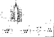
图1是显示本发明实施例1的载荷检测装置的基本结构的剖面图;1 is a sectional view showing the basic structure of a load detection device according to
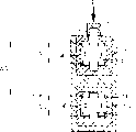
图2是显示本发明实施例2的载荷检测装置的基本结构的剖面图;2 is a cross-sectional view showing the basic structure of a load detection device according to
图3是显示本发明实施例2的载荷检测装置的一种变化形式的剖面图;Fig. 3 is a sectional view showing a variation of the load detection device of
图4是显示本发明实施例3的载荷检测装置的基本结构的剖面图;4 is a sectional view showing the basic structure of a load detection device according to
图5是显示本发明实施例3的载荷检测装置的一种变化形式的剖面图;Fig. 5 is a sectional view showing a variation of the load detection device of
图6是显示本发明实施例4的载荷检测装置的基本结构的剖面图;6 is a cross-sectional view showing the basic structure of a load detection device according to
图7是显示本发明实施例4的载荷检测装置的一种变化形式的剖面图;Fig. 7 is a sectional view showing a variation of the load detection device of
图8是显示本发明实施例5的载荷检测装置的基本结构的剖面图;8 is a cross-sectional view showing the basic structure of a load detection device according to
图9是显示本发明实施例5的载荷检测装置的一种变化形式1的剖面图;Fig. 9 is a cross-sectional view showing a
图10是显示本发明实施例5的载荷检测装置的一种变化形式2的剖面图;Fig. 10 is a sectional view showing a
图11是显示本发明实施例6的载荷检测装置的基本结构的框图;Fig. 11 is a block diagram showing the basic structure of a load detection device according to
图12是显示本发明实施例6的载荷检测装置的信号处理器电路的结构的剖面图;12 is a cross-sectional view showing the structure of a signal processor circuit of a load detection device according to
图13是显示本发明实施例6的载荷检测装置的一种变化形式1的剖面图;Fig. 13 is a sectional view showing a
图14是显示本发明实施例6的载荷检测装置的一种变化形式2的剖面图;Fig. 14 is a sectional view showing a
图15是显示本发明实施例6的载荷检测装置的一种变化形式3的剖面图;Fig. 15 is a sectional view showing a
图16是显示本发明实施例6的载荷检测装置的一种变化形式3的剖面图;Fig. 16 is a sectional view showing a
图17是显示本发明实施例7的载荷检测装置的基本结构的剖面图;Fig. 17 is a sectional view showing the basic structure of a load detecting device according to
图18是显示本发明实施例7的载荷检测装置的一种变化形式1的剖面图;Fig. 18 is a cross-sectional view showing a
图19是显示本发明实施例7的载荷检测装置的一种变化形式2的剖面图;Fig. 19 is a cross-sectional view showing a
图20是显示本发明实施例7的载荷检测装置的一种变化形式3的剖面图;Fig. 20 is a sectional view showing a
图21是显示本发明实施例8的载荷检测装置的基本结构的剖面图;Fig. 21 is a sectional view showing the basic structure of a load detecting device according to
图22是显示本发明实施例8的载荷检测装置的一种变化形式1的剖面图;Fig. 22 is a cross-sectional view showing a
图23是显示本发明实施例8的载荷检测装置的一种变化形式2的剖面图;Fig. 23 is a cross-sectional view showing a
图24是显示图23的载荷检测装置的信号处理器电路的结构的框图;Fig. 24 is a block diagram showing the structure of the signal processor circuit of the load detection device of Fig. 23;
图25是显示本发明应用1的摩托车盘式制动系统的结构图;Fig. 25 is a structural diagram showing the motorcycle disc brake system of
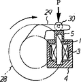
图26是显示本发明应用2的摩托车加速器系统的结构图;Fig. 26 is a structural diagram showing the motorcycle accelerator system of
图27是沿图26箭头方向的图;Fig. 27 is a figure along the arrow direction of Fig. 26;
图28是显示本发明应用3的物体位置检测系统的结构图;FIG. 28 is a structural diagram showing an object position detection system of
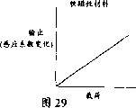
图29是软磁性材料的输出特性的图;Fig. 29 is a graph of output characteristics of a soft magnetic material;
图30是超磁致伸缩材料的输出特性的图;Fig. 30 is a graph of output characteristics of a giant magnetostrictive material;
图31是显示输出差值ΔV与载荷差值ΔP之间关系的图;以及Fig. 31 is a graph showing the relationship between the output difference ΔV and the load difference ΔP; and
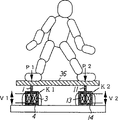
图32是显示本发明应用3的人体姿势检测系统的结构图。FIG. 32 is a structural diagram showing a human body posture detection system of
实现本发明的最佳模式BEST MODE FOR CARRYING OUT THE INVENTION
以下参照附图说明本发明的实施例。Embodiments of the present invention will be described below with reference to the drawings.
实施例1Example 1
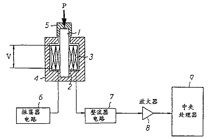
图1是显示本发明实施例1的载荷检测装置的基本结构的剖面图。Fig. 1 is a sectional view showing the basic structure of a load detecting device according to
在图1中,标号1表示实心杆状磁体,该磁体被磁化线圈2和检测线圈3所包围。所以,磁体1设置在磁化线圈2和检测线圈3的轴心处,并且,磁体1、磁化线圈2和检测线圈3被包封在一由磁性材料制成的磁屏蔽外罩4内。磁化线圈2和检测线圈是电绝缘的。In FIG. 1 ,
磁体1由诸如铁合金、铬铁、镍铁、钴铁、纯铁、硅铁、坡莫合金等之类的磁性材料、软磁材料或超磁致伸缩材料制成,其相对磁屏蔽外罩4向上突出的顶端嵌有一由非磁性材料制成的接头5。接头5用作一减震器以及一磁屏蔽部件。
一振荡器电路6电连接于磁化线圈2,一整流器电路7、一放大器8以及用作一处理器的CPU9电连接于检测电路3。An
以下说明上述载荷装置的功能。The function of the loading device described above will be described below.
振荡器电路6所驱动的磁化线圈2使磁体1磁化,并且,当载荷P经由接头5沿轴向方向作用到被磁化了的磁体1上时,如图1所示,一压力就会作用于磁体1,从而因磁致伸缩作用而减少了该磁体的磁导率并导致感应系数的变化。这就会使得磁化线圈2两端的电压发生变化,同时,检测线圈3两端的电压V也会按线圈匝数的比例发生变化。磁致伸缩作用对超磁致伸缩材料来说在数百ppm至数千ppm的范围内,而对其它材料来说则在数十ppm的范围内。The magnetizing
电压V在整流电路7中整流之后被放大器8所放大,并被作为一输出信号输入给CPU9,从而,CPU9根据电压V来计算出作用于磁体1的载荷P的大小。The voltage V is amplified by the
所以,在本实施例中,所述载荷检测设备由一磁体1、一用于对该磁体进行磁化的磁化线圈2、一用于检测电压V的检测线圈3、一用于对上述组件进行磁屏蔽的磁屏蔽外罩4等构成,因此,该设备结构简单,机械强度高、尺寸较小、重量轻且易于使用、适于移动。Therefore, in this embodiment, the load detection device is composed of a
此外,在这一实施例的载荷检测装置中,具有小直径的磁体1设置在磁化线圈2的轴心处,在该位置处,磁通量的密度为最高,因此,可将对上述磁体进行磁化所需的能量保持为最小并使感应系数也较小,所以,能很容易地提供有利于检测的高频驱力。In addition, in the load detecting device of this embodiment, the
再有,在这一实施例的载荷检测装置中,载荷P直接作用于磁体1,并且,根据因载荷P所导致的磁体1的磁导率的变化而引起的感应系数的变化来检测载荷P,因此,检测时不会有移动,从而,直接响应率高,易于调整,有较小的磁滞。特别是在将超磁致伸缩材料用作磁体1时,可以最佳地获得大的检测输出。此外,由一磁体1、一磁化线圈2和一检测线圈3构成的上述检测部被磁屏蔽外罩4所磁屏蔽,因此,检测结果不可能受到磁力影响,从而能高精度地检测载荷P。Also, in the load detection device of this embodiment, the load P acts directly on the
尽管在本实施例中使用了磁化线圈2和检测线圈3,但是,也可以只用磁化线圈2来检测所说的电压(这同样适用于以下的实施例)。Although the magnetizing
实施例2Example 2
以下参照图2说明本发明的实施例2。图2是显示本发明这一实施例的载荷检测装置的基本结构的剖面图,在图2中,略去了所说的磁化线圈和信号处理器电路。
本实施例的载荷检测设备设置成以串联且共轴的方式垂直地设置有两个检测部K1、K2,这两个检测部被一个由非磁性材料制成的外罩10所覆盖。The load detection device of this embodiment is arranged to have two detection parts K1 , K2 vertically arranged in series and coaxially, and these two detection parts are covered by a
检测部K1包括一磁体1、一设置在上述磁体周围的检测线圈3以及一用于包封住这些部件的磁屏蔽外罩4,与此相似,检测部K2包括一磁体11、一设置在上述磁体周围的检测线圈13以及一用于包封住这些部件的磁屏蔽外罩14,磁体11通过由非磁性材料制成的接头15与检测部K1的磁屏蔽外罩4相连。The detection part K1 includes a
在这一实施例的载荷检测装置中,检测部K1、K2中的磁体1、11由具有不同磁致伸缩常数的材料制成,通过接头5作用于磁体1的轴向载荷同样地通过接头15作用于另一个磁体11。In the load detection device of this embodiment, the
所以,在这一实施例的载荷检测装置中,有相同的载荷P分别作用于检测部K1、K2中的磁体1、11,但是,由于这些磁体1、11的磁致伸缩常数是彼此不同的,故检测部K1、K2中的感应系数变化也是彼此不同的,所以,检测线圈3、13中因感应系数变化的不同而产生的电压V1、V2也有彼此不同的值。Therefore, in the load detection device of this embodiment, the same load P acts on the
检测线圈3、13中所产生的电压V1、V2受环境状态(温度或湿度)等的影响,但是,在本实施例的检测装置中,可将电压V1、V2之差(V2-V1)检测为输出差ΔV,以便能在不受环境状态等的影响的情况下检测到载荷P。The voltages V1 and V2 generated in the detection coils 3 and 13 are affected by the environmental conditions (temperature or humidity), but, in the detection device of this embodiment, the difference (V2-V1) between the voltages V1 and V2 can be detected is the output difference ΔV so that the load P can be detected without being affected by the environmental state or the like.
此外,在本实施例中还能获得与在实施例1中相同的效果,由于精度高,故可以有较大的放大系数,并且,可将普通材料用作磁体1、11以代替昂贵的超磁致伸缩材料,因此,可以进一步减少所述装置的成本。In addition, in this embodiment, the same effect as in
尽管可将具有不同磁致伸缩常数的材料用于磁体1、11以作为用于产生检测部K1、K2中感应系数变化之差的装置,但是,也可以使用具有不同磁导率的材料,或者,可以使用通过热处理、表面处理(电镀、碳化、氮化处理等)或加工硬化(喷丸硬化等)而导致的具有不同硬度的相同材料(例如,一种材料经过处理,另一种材料不经过处理)。Although materials with different magnetostrictive constants may be used for the
此外,如图3所示,可将磁体1、11和检测线圈3、13包封在一个成整体的磁屏蔽外罩4内。在这种情况下,可以进一步减少重量并使尺寸变得较小,从而使部件数量较少并降低成本。In addition, as shown in FIG. 3 , the
实施例3Example 3
以下参照图4说明本发明的实施例3。图4是显示该实施例的载荷检测装置的基本结构的剖面图,在图4中,也略去了所说的磁化线圈和信号处理器电路。
这一实施例的载荷装置也设置成以串联的方式垂直地设置有两个检测部K1、K2,这两个检测部被一个由非磁性材料制成的外罩10所覆盖。但是,提供了一个为检测部K1、K2所共用的磁体1。对磁体1的位于检测部K1一侧的部分1a作局部的热处理。磁体1的这一部分1a可仅包括表面。The loading device of this embodiment is also arranged vertically in series with two detection parts K1, K2, and these two detection parts are covered by a
在如上所述那样对磁体1的一部分1a作热处理时,该部分1a的金属结构会发生变化,从而使该部分1a的磁导率不同于其它部分的磁导率,这就与使用了两个具有不同磁导率的磁体有同样的效果。所以,与上述实施例2相类似,由于检测线圈3、13中所产生的电压V1、V2之差(V2-V1)被检测为输出差ΔV,故可在不受环境状态等的影响的情况下高精度地检测出直接作用于磁体1的载荷P。When a portion 1a of the
此外,在本实施例中使用了一个单个的磁体1,从而能确保有较高的检测精度。In addition, a
另外,如图5所示,可将磁体1和检测线圈3、13包封在一个成整体的磁屏蔽外罩4内。在这种情况下,可以进一步减少重量并使尺寸变得较小,从而使部件数量较少并降低成本。In addition, as shown in FIG. 5 , the
实施例4Example 4
以下参照图6说明本发明的实施例4。图6是显示该实施例的载荷检测装置的基本结构的剖面图,在图6中,也略去了所说的磁化线圈和信号处理器电路。
这一实施例的载荷装置也设置成以串联的方式垂直地设置有两个检测部K1、K2,这两个检测部被一个由非磁性材料制成的外罩10所覆盖,但是,提供了一个为检测部K1、K2所共用的磁体1,并且,局部地减小了磁体1的位于检测部K1一侧的部分1a的直径。The loading device of this embodiment is also arranged to be vertically provided with two detection portions K1, K2 in series, and these two detection portions are covered by an
在减小磁体1的一部分1a的直径时,由载荷P所导致的部分1a上的应力会变得比其它部分的应力大,这就与使用了两个由不同材料(磁致伸缩常数)构成的磁体有同样的效果。所以,与上述实施例2、3相类似,由于检测线圈3、13中所产生的电压V1、V2之差(V2-V1)被检测为输出差ΔV,故可在不受环境状态等的影响的情况下高精度地检测出直接作用于磁体1的载荷P。When reducing the diameter of a part 1a of the
此外,在本实施例中也使用了一个单个的磁体1,从而能确保有较高的检测精度。In addition, a
另外,如图7所示,可将磁体1和检测线圈3、13包封在一个成整体的磁屏蔽外罩4内。在这种情况下,可以进一步减少重量并使尺寸变得较小,从而使部件数量较少并降低成本。In addition, as shown in FIG. 7 , the
实施例5Example 5
以下参照图8说明本发明的实施例5。图8是显示该实施例的载荷检测装置的基本结构的剖面图,在图8中,也略去了所说的磁化线圈和信号处理器电路。
这一实施例的载荷装置也设置成以串联的方式垂直地设置有两个检测部K1、K2,这两个检测部被一个由非磁性材料制成的外罩10所覆盖,但是,检测部K1、K2是完全独立的,并且,作用于检测部K1的磁体1的载荷P不会作用于检测部K2的磁体11。The loading device of this embodiment is also arranged to be vertically provided with two detection parts K1, K2 in series, and these two detection parts are covered by an
所以,在本实施例的载荷检测装置中,载荷P仅作用于检测部K1中的磁体1,因此,检测部分K2起一空载体的作用,以便补偿因环境状态等的差异所造成的检测误差,从而,由于检测线圈3、13中所产生的电压V1、V2之差(V2-V1)被检测为输出差ΔV,故可在不受环境状态等的影响的情况下高精度地检测出直接作用于磁体1的载荷P。Therefore, in the load detection device of the present embodiment, the load P acts only on the
此外,在本实施例中,可将同样的材料用于磁体1、11,从而可进一步地降低成本。Furthermore, in this embodiment, the same material can be used for the
如图9所示,可将磁体1、11和检测线圈3、13包封在一个成整体的磁屏蔽外罩4内。在这种情况下,可以进一步减少重量并使尺寸变得较小,从而使部件数量较少并降低成本。As shown in FIG. 9 , the
另外,如图10所示,可彼此独立地设置检测部K1、K2。在这种情况下,只需将检测部K1设置在实际接收载荷的位置,这就能使得尺寸减半,从而改善安装的自由度。In addition, as shown in FIG. 10, the detection parts K1, K2 may be provided independently of each other. In this case, it is only necessary to dispose the detection portion K1 at the position where the load is actually received, which enables the size to be halved, thereby improving the degree of freedom of installation.
实施例6Example 6
以下参照图11和12说明本发明的实施例6。图11是显示该实施例的载荷检测装置的基本结构的剖面图,图12是显示上述载荷检测装置的信号处理器电路的结构的框图。
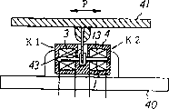
如图11所示,这一实施例的载荷装置设置成以彼此相对的方式将两个检测部K1、K2设置在一固定板40上,一设置在可横向移动的移动板41的底面上的突出部41a与检测部K1、K2中的磁体1、11的一端相接触。在图11中,标号3、13表示检测线圈,标号4、14表示屏蔽外罩,检测线圈3、13分别被磁化电路(未示出)所磁化。As shown in Fig. 11, the loading device of this embodiment is arranged such that the two detection parts K1, K2 are arranged on a fixed
在本实施例的载荷检测装置中,可检测出沿向左和向右方向之一作用于移动板41的载荷P。也就是说,如图12所示,在整流器电路7、17对来自检测部K1、K2的输出(电压)V1、V2进行整流,并在平滑电路12、22中使该电压变得平滑,然后将该电压输入到差分放大器电路8中,在该差分放大器电路中,确定并放大所述电压的差值ΔV(=V2-V1)以便输出。根据该输出结果计算出沿向右和向左方向作用于可移动板41的载荷P。In the load detecting device of the present embodiment, the load P acting on the moving
在如上所述的实施例中,用简单的结构就可检测出沿向右和向左方向的载荷P,并且,还可获得与前述实施例1-5同样的效果。In the embodiment as described above, the load P in the rightward and leftward directions can be detected with a simple structure, and the same effects as those of the aforementioned embodiments 1-5 can also be obtained.
如图13所示,可采用这样一种结构,其中,在固定板40上以彼此相对且独立的方式设置有两个检测部K1、K2,设置在可横向移动的移动板41的底面上的两个突出部41a中的各个突出部与检测部K1、K2中的各个磁体1、11相接触。在这种情况下,如图14所示,可将上述移动板分成两部分。As shown in FIG. 13, a structure may be adopted in which two detection parts K1, K2 are provided on the fixed
另外,如图15和图16所示,可在固定板40上以彼此相对的方式设置有四个检测部K1、K2、K3、K4,以可倾斜方式设置在这些检测部的中心的杆状杠杆42与检测部K1-K4中的磁体1、11、1′、11′的一端相接触,因此,杠杆42可构成一操纵杆。In addition, as shown in Fig. 15 and Fig. 16, four detection parts K1, K2, K3, K4 can be provided on the fixed
在上述结构中,由于能检测到来自相对向的检测部K1、K2与相对向的检测部K3、K4的输出信号之差,故可以分别检测到横向和纵方向上的分力P1、P2,从而,可根据这些呈矢量形式的分力P1、P2确定作用于杠杆42的载荷P的大小与方向。In the above structure, since the difference between the output signals from the opposite detection parts K1, K2 and the opposite detection parts K3, K4 can be detected, the component forces P1, P2 in the horizontal and vertical directions can be detected respectively, Therefore, the magnitude and direction of the load P acting on the lever 42 can be determined according to these component forces P1 and P2 in vector form.
实施例7Example 7
以下参照图17说明本发明的实施例7。图17是显示该实施例的载荷检测装置的基本结构的剖面图。
这一实施例的载荷装置固定在固定板40上并包括两个检测部K1、K2,它们设置成一共用的实心杆状磁体1包封在检测线圈3、13的轴心内,所述检测线圈则共轴地设置在一共用的磁屏蔽外罩4内。在这一载荷检测装置内,磁屏蔽外罩4接收磁体1的两端,与可横向移动的移动板41的底面相连的平板43位于磁体1的中心部分处。The loading device of this embodiment is fixed on the fixed
在本实施例的载荷检测装置中,当沿向右或向左方向的载荷P作用于移动板41时,载荷P就会通过平板43作用于磁体1的上述中心部分,从而挤压(位于检测部K1一侧的)左半边或(位于检测部K2一侧的)右半边,因此,与前述实施例6相类似,可以检测出沿两个方向作用于移动板41的载荷P。In the load detecting device of the present embodiment, when the load P in the rightward or leftward direction acts on the moving
在本发明的这一实施例中,由于磁体1接收位于所述中心部分的载荷,所以,如果有沿向左方向的载荷P作用于磁体1,那么,就会有压载作用于磁体1的左面一半并且没有载荷作用于右面一半。相反,如果有沿向右方向的载荷P作用于磁体1,那么,就会有压载作用于磁体1的右面一半并且没有载荷作用于左面一半。In this embodiment of the invention, since the
在如上所述的本实施例载荷检测装置中,由于载荷P只作用于(位于检测部K1一侧的)左半边或(位于检测部K2一侧的)右半边,故未受载荷作用的检测部K1或K2可起一空载体的作用,以便如在实施例5中那样补偿因环境状态的差异所造成的检测误差,并且,由于可将检测部K1、K2之差检测为一输出差,故可在不受环境状态等的影响的情况下检测出沿向左和向右方向之一作用于移动板41的载荷P。In the load detection device of the present embodiment as described above, since the load P only acts on the left half (on the side of the detection part K1) or the right half (on the side of the detection part K2), it is not detected by the load. The part K1 or K2 can function as an empty carrier to compensate for the detection error caused by the difference in the environmental state as in
如图18所示,如果所述载荷检测装置设置成该载荷检测装置中的共用磁体1穿过磁屏蔽外罩4,并且,该磁体的两端被设置在固定板40上的突出部40a所接收,那么,由于没有载荷P作用在磁屏蔽外罩4上,故磁屏蔽外罩4不需要有高机械强度,从而,可在使壁面厚度变薄的情况下减少所述载荷装置的重量。As shown in Figure 18, if the load detection device is arranged such that the
如图19所示,所述载荷检测装置设置成用固定在移动板41上的平板44将该装置分成检测部K1、K2,检测部K1、K2中的磁体1、11的一端被平板44所接收,而另一端则被设置在固定板40上的突出部40a所接收。在这种情况下,如图20所示,所述载荷检测装置可设置成将各具有作为单个主体的相同结构的检测部K1、K2以彼此相共轴且相对的方式设置在平板44的两侧。As shown in Fig. 19, the load detection device is arranged such that the device is divided into detection parts K1, K2 by a
实施例8Example 8
以下参照图21说明本发明的实施例8。图21是显示该实施例的载荷检测装置的基本结构的剖面图。
这一实施例的载荷装置固定在可横向移动的移动板41的底面上并包括两个检测部K1、K2,它们设置成一共用的实心杆状磁体1穿过检测线圈3、13的轴心,所述检测线圈则共轴地设置在一共用的屏蔽外罩4内。在这一载荷检测装置内,磁体1的中心部分固定在磁屏蔽外罩4上,并且,磁体1相对磁屏蔽外罩4侧向突出的两端分别与设置在固定板40上的突出部40a相接触。The loading device of this embodiment is fixed on the bottom surface of the
在本实施例的载荷检测装置中,与前述实施例6相似,可检测出沿两个方向作用于移动板41的载荷P。但是,由于磁体1固定在中心部分,所以,如果有沿向左方向的载荷P作用于磁体1,那么,就会有压载作用于磁体1的右面一半并且没有载荷作用于左面一半。相反,如果有沿向右方向的载荷P作用于磁体1,那么,就会有压载作用于磁体1的左面一半并且没有载荷作用于右面一半。In the load detecting device of this embodiment, similarly to the
在如上所述的本实施例载荷检测装置中,由于载荷P只作用于(位于检测部K1一侧的)左半边或(位于检测部K2一侧的)右半边,故未受载荷作用的检测部K1或K2可起一空载体的作用,以便如在实施例5中那样补偿因环境状态的差异所造成的检测误差,并且,由于可将检测部K1、K2之差检测为一输出差,故可在不受环境状态等的影响的情况下检测出沿向左和向右方向之一作用于移动板41的载荷P。In the load detection device of the present embodiment as described above, since the load P only acts on the left half (on the side of the detection part K1) or the right half (on the side of the detection part K2), it is not detected by the load. The part K1 or K2 can function as an empty carrier to compensate for the detection error caused by the difference in the environmental state as in
如图22所示,可采用这样的结构,在这种结构中,所述载荷检测装置固定在固定板40上,并且,设置在移动板41底面上的突出部41a与磁体1穿过该载荷检测装置中心部分的两端相接触。As shown in FIG. 22, a structure may be adopted in which the load detection device is fixed on the fixed
另外,如图23所示,可采用这样的结构,在这种结构中,有多个载荷检测装置(图23中作为实例示出了两个)设置在固定板40上,并且,设置在可横向移动的移动板41、41′底面上的突出部41a、41a′与相应磁体1、11穿过该载荷检测装置中心部分的两端相接触。In addition, as shown in FIG. 23, a structure may be adopted in which a plurality of load detection devices (two are shown as an example in FIG. Protrusions 41a, 41a' on the bottom surface of the laterally moving
在如图23所示那样设置有两个载荷检测装置的情况下,在如图24的框图所示的整流器电路7、17、7′、17′内分别对来自前述两个载荷检测装置中的检测部K1、K2、K1′、K2′的输出(电压)V11、V12、V21、V22进行整流,并在平滑电路12、22、12′、22′中使上述电压变得平滑,然后将该电压输入到差分放大器电路8、8′中,在该差分放大器电路中,确定并放大电压差值ΔV1(=V12-V11)、ΔV2(=V22-V21)以便输出。还将差值ΔV1、ΔV2输入给差分放大器电路18,在该差分放大器电路中,确定并放大所述差值的差值ΔV(=ΔV1-ΔV2)以便输出,并根据该差值ΔV确定出作用于两个可移动板41、41′的载荷P、P′之差。In the case where two load detection devices are provided as shown in FIG. 23, the
应用1
以下参照图25说明本发明载荷检测装置的应用1。
图25是摩托车的盘式制动系统的结构图。本发明的载荷检测装置(如实施例1所示的同一个装置,在图25中,用相同的标号表示与图1中相同的部件)设置在摩托车的手柄21内,磁体1的一端通过接头5与制动手柄22的中间部分相接触。Fig. 25 is a structural diagram of a disc brake system of a motorcycle. The load detecting device of the present invention (the same device as shown in
手柄21内包含有一信号处理器电路23,它与所述载荷检测装置的检测线圈3相连,信号处理器电路23电连接于控制器24。The
另一方面,在图25中,标号25表示一盘形制动盘,它可同车轮(未示出)一道旋转,所述制动盘的两侧设置有卡钳27,它们用于将衬垫26压在制动盘25的两侧上,以形成必要的制动力。卡钳27电连接于控制器24。On the other hand, in Fig. 25, reference numeral 25 denotes a disc-shaped brake disc, which can rotate together with the wheel (not shown), and calipers 27 are provided on both sides of the brake disc, and they are used to place the pad 26 is pressed on both sides of the brake disc 25 to form the necessary braking force. The caliper 27 is electrically connected to the
当摩托车的骑车人抓持住制动手柄22进行操作时,就将与因骑车人的抓持力而作用于载荷检测装置的磁体1的载荷P成比例的输出信号输入给信号处理器电路23,在该信号处理器电路中,对所输入的输出信号进行处理,从而将其转换成输入给控制器24的电压。然后,控制器24计算出载荷并将与载荷P成比例的控制信号输入给卡钳27,以便控制该卡钳进行驱动,卡钳27将衬垫26压在制动盘25的两面上以形成所需的制动力。When the rider of the motorcycle grips the brake handle 22 for operation, an output signal proportional to the load P acting on the
在上述实施中,与骑车人作用在制动手柄22上的抓持力有关的载荷P可直接被载荷检测装置所接收以便进行检测,因此,可提高对制动器的操作感觉。In the above implementation, the load P related to the rider's grip force on the brake handle 22 can be directly received by the load detection device for detection, thereby improving the operating feeling of the brake.
此外,信号处理器电路23提供了机械制动系统所无法获得的制动特性。In addition, the
应用2
以下参照图26和图27说明本发明载荷检测装置的应用2。
图26是摩托车的加速器系统的结构图,图27是沿图26中箭头A方向的图。本发明的载荷检测装置(如实施例1所示的同一个装置,在图26和图27中,用相同的标号表示与图1中相同的部件)设置在摩托车的手柄21内,磁体1的接头5通过滚柱30与杠杆29的一端相接触,而所述杠杆则与手柄28成整体。Fig. 26 is a structural diagram of the accelerator system of the motorcycle, and Fig. 27 is a diagram along the direction of arrow A in Fig. 26 . The load detecting device of the present invention (the same device as shown in
手柄28内包含有一信号处理器电路23,它与所述载荷检测装置的检测线圈3相连,信号处理器电路23电连接于控制器24。The
另一方面,在图26中,标号31表示一发动机,标号32表示一进气管,它与发动权31的进气系统相连接;进气管32的中间设置有一化油器33,进气管32相对化油器33的上游处设置有一节气阀34。节气阀34附近设置有一启动器35,它用于开启/关闭节气阀34,启动器35电连接于控制器24。On the other hand, in Fig. 26,
当摩托车的骑车人沿图27中箭头方向操纵手柄28时,就通过杠杆29和滚柱30将骑车人的操纵力传给所述载荷检测装置,因此,载荷P会沿轴向方向作用于该载荷检测装置的磁体1。然后,将与载荷P成比例的输出信号从所述载荷检测装置输入给信号处理器电路23,在该信号处理器电路中,对所输入的输出信号进行处理,从而将其转换成输入给控制器24的电压。然后,控制器24计算出载荷P并将与载荷P成比例的控制信号输出给启动器35,从而控制启动器35进行驱动,启动器35用于开启/关闭节气阀34以控制进入发动机31的空气量。When the rider of the motorcycle manipulates the
在上述应用中,不需要如通常那样显著地转动手柄,因此,骑车人不需要扭手腕,从而改善了节气操作。In the above application, there is no need to turn the handlebar as much as usual, and therefore, the rider does not need to twist the wrist, thereby improving gas-saving operation.
此外,信号处理器电路23提供了机械装置所无法获得的节气控制,因此,对发动机31中的混合物的燃烧控制会获得高输入功率、低排放、清洁燃烧等。In addition, the
应用3
以下参照图28说明本发明载荷检测装置的应用3。图28是一物体位置检测系统的结构图。
本应用示出了这样一个实例,其中,在用于检测在水平梁36上作线性运动的物体W的位置的装置中使用了本发明的载荷检测装置(如实施例1所示的同一个装置)。This application shows an example in which the load detection device of the present invention (the same device as shown in Embodiment 1) is used in a device for detecting the position of an object W linearly moving on a
本发明的载荷检测装置的检测部K1、K2支承着梁31的两端,检测部K1、K2分别由磁体1、11和检测线圈3、13以及包封这些组件的磁屏蔽外罩4、14构成,磁体1、11的上端通过接头5、15支承着梁36的两端。The detection parts K1, K2 of the load detection device of the present invention support the two ends of the
假定已知两个检测部K1、K2之间的距离L并且梁36的重量可以忽略不计,检测部K1、K2接收物体W的重量P,载荷P1、P2分别作用于检测部K1、K2中的磁体1、11,并且,载荷P1、P2根据位置x(距载荷P的加载点的距离)而改变自身数值,那么,P与P1、P2的关系就可写成:Assuming that the distance L between the two detection parts K1, K2 is known and the weight of the
P=P1+P2 (1)P=P1+P2 (1)
考虑到物体W的重量P对所述加载点的力矩平衡,有下式:Considering the moment balance of the weight P of the object W on the loading point, the following formula is given:
P1·x=P2(L·X) (2)P1·x=P2(L·X) (2)
可根据等式(1)、(2)将物体W的位置x写成:According to equations (1) and (2), the position x of object W can be written as:
x=P2·L/(P1+P2) (3)x=P2·L/(P1+P2) (3)
所以,如果载荷检测装置中的检测部K1、K2检测到了载荷P1、P2,那么,就可根据等式(3)计算出物体W的位置x。Therefore, if the detection parts K1, K2 in the load detection device detect the loads P1, P2, then the position x of the object W can be calculated according to the equation (3).
在已知物体W的重量P(=P1+P2)时,等式(3)可写成:When the weight P(=P1+P2) of the object W is known, equation (3) can be written as:
x=P2·L/P (3′)x=P2·L/P (3′)
那么,如果载荷P2仅被一个检测部K2检测到,则可根据等式(3′)计算出物体W的位置x。Then, if the load P2 is detected by only one detection section K2, the position x of the object W can be calculated according to the equation (3').
作用于检测部K1、K2的载荷P1、P2之差ΔP是:The difference ΔP between the loads P1 and P2 acting on the detection parts K1 and K2 is:
ΔP=P1-P2 (4)ΔP=P1-P2 (4)
检测部K1、K2的输出值之差ΔV是:The difference ΔV between the output values of the detection parts K1 and K2 is:
ΔV=V1-V2 (4′)ΔV=V1-V2 (4′)
所以,还可将上述电路设置成能检测所说的输出差ΔV。Therefore, the above circuit can also be arranged to detect said output difference ΔV.
一般地说,在将软磁性材料用于磁体1的情况下,如果适当地设定了载荷范围以及磁化电流/频率,那么,各个传感器的输出(感应系数的变化)就如图29所示那样是线性的。另一方面,在用超磁致伸缩材料的情况下,开始时的增长会很大,但随着载荷的僧加,输出增加率会逐渐减小。In general, when a soft magnetic material is used for the
就利用输出差的装置而言,当载荷仅作用于一个传感器而不作用于另一个传感器时,其输出特性与相应的各个传感器的输出特性相类似,因此,可按与载荷差一一对应的方式确定传感器的输出差,从而能对所说的系统进行控制。特别是在使用超磁致伸缩材料时,可获得较大的输出,从而能提高温度特性等的精度。此外,不会施加据认为是不利于机械强度的拉伸应力,因此,能获得较广的载荷范围。As far as the device using the output difference is concerned, when the load only acts on one sensor and not on the other sensor, its output characteristics are similar to those of the corresponding sensors, so it can be used in a one-to-one correspondence with the load difference. The output difference of the sensor is determined by means of a method, so that the system can be controlled. In particular, when a giant magnetostrictive material is used, a large output can be obtained, and the accuracy of temperature characteristics and the like can be improved. In addition, tensile stress, which is considered to be detrimental to mechanical strength, is not applied, and therefore, a wide load range can be obtained.
还有,在有输出差的情况下,当有大载荷作用于一个传感器并有小载荷作用于另一个传感器时,就软磁性材料而言,可按与任何载荷范围内的载荷差一一对应的方式确定传感器的输出差,而就超磁致伸缩材料而言,输出的增加率会因载荷范围的不同而不同,结果,对各个载荷范围来说,载荷差是不同的。Also, in the case of output difference, when a large load acts on one sensor and a small load acts on the other sensor, as far as soft magnetic materials are concerned, it can be one-to-one corresponding to the load difference in any load range The output difference of the sensor is determined by the method, and for the giant magnetostrictive material, the increase rate of the output will be different due to the different load ranges, and as a result, the load difference is different for each load range.
依照前述内容,适当地设定用于磁体1的磁性材料和工作传感器的结构或构成以及诸如载荷范围和磁化电流/频率之类的控制量,因此,可按与等式(4)中的ΔP一一对应的方式确定等式(4′)中的ΔV。特别是在使用软磁性材料时,ΔV的值相对ΔP而言是线性的,如图31所示,从而,能提高可控性。尽管在图31中所述输出的中值是零,但是,也可以用一电路来调整该中值。According to the foregoing, the magnetic material used for the
此外,如果图28所示的物体W是图32所示的人,那么,利用检测部K1、K2的输出信号的和与差可检测出重量P以及左侧和右侧载荷P1、P2之差,因此,可断定人在梁36上的姿势。在这种情况下,可对梁36进行分割。In addition, if the object W shown in FIG. 28 is a person shown in FIG. 32, the weight P and the difference between the left and right loads P1 and P2 can be detected by using the sum and difference of the output signals of the detection parts K1 and K2. , therefore, the posture of the person on the
本发明的效果Effect of the present invention
从以上的说明中可以清楚地看到,依照本发明,所述载荷检测装置由一实心杆状磁体以及用于对该磁体进行磁化的线圈构成,因此,所述磁体的直径可以较小,其结构也能得以简化,从而能提供一种机械强度高、动态范围广、具有较小尺寸、重量轻、成本降低的并易于使用、适于移动的装置。As can be clearly seen from the above description, according to the present invention, the load detection device is composed of a solid rod-shaped magnet and a coil for magnetizing the magnet, therefore, the diameter of the magnet can be relatively small, and its The structure can also be simplified so that a device with high mechanical strength, wide dynamic range, small size, light weight, reduced cost and easy to use, suitable for movement can be provided.
此外,依照本发明,一具有小直径的磁体设置在一线圈的轴心处,在该位置处,磁通量的密度为最高,因此,可将对上述磁体进行磁化所需的能量保持为最小并使感应系数也较小,所以,能很容易地提供有利于检测的高频驱力。Furthermore, according to the present invention, a magnet having a small diameter is placed at the center of the axis of a coil at the position where the density of magnetic flux is the highest, so that the energy required to magnetize the above-mentioned magnet can be kept to a minimum and the The inductance is also small, so the high frequency driving force that is useful for detection can be easily provided.
再有,依照本发明,载荷直接作用于一磁体,并且,根据因载荷所导致的磁体的磁导率的变化而引起的感应系数的变化来检测所说的载荷,因此,不会有移动伴随着检测,从而会提供这样一种结构,该结构能有较高的直接响应率,并易于调整,有较小的磁滞,且不可能受到磁力的影响。Furthermore, according to the present invention, a load is directly applied to a magnet, and the load is detected based on a change in inductance caused by a change in the magnetic permeability of the magnet caused by the load, so that there is no movement accompanying This provides a structure that has a high direct response rate, is easy to adjust, has low hysteresis, and is unlikely to be affected by magnetic forces.
Claims (17)
Applications Claiming Priority (4)
| Application Number | Priority Date | Filing Date | Title |
|---|---|---|---|
| JP360103/1997 | 1997-12-26 | ||
| JP36010397 | 1997-12-26 | ||
| JP36904998A JP4217321B2 (en) | 1997-12-26 | 1998-12-25 | Load detection device |
| JP369049/1998 | 1998-12-25 |
Publications (2)
| Publication Number | Publication Date |
|---|---|
| CN1253622A CN1253622A (en) | 2000-05-17 |
| CN1175257C true CN1175257C (en) | 2004-11-10 |
Family
ID=26581076
Family Applications (1)
| Application Number | Title | Priority Date | Filing Date |
|---|---|---|---|
| CNB988044285A Expired - Fee Related CN1175257C (en) | 1997-12-26 | 1998-12-25 | Load detection device |
Country Status (6)
| Country | Link |
|---|---|
| US (1) | US6345544B1 (en) |
| EP (1) | EP0964232B1 (en) |
| JP (1) | JP4217321B2 (en) |
| CN (1) | CN1175257C (en) |
| DE (1) | DE69837702T2 (en) |
| WO (1) | WO1999034182A1 (en) |
Families Citing this family (36)
| Publication number | Priority date | Publication date | Assignee | Title |
|---|---|---|---|---|
| DE19924002A1 (en) * | 1999-05-26 | 2000-11-30 | Wittenstein Gmbh & Co Kg | Sensor, in particular magnetiostrictive or magnetoelastic sensor |
| JP2003517808A (en) | 1999-08-31 | 2003-05-27 | デルタグライド、インコーポレイテッド | Power assist vehicle |
| JP2002286743A (en) * | 2001-03-22 | 2002-10-03 | Kayaba Ind Co Ltd | Vibration / oscillation level measuring device and its measuring method |
| US7070019B2 (en) * | 2001-06-21 | 2006-07-04 | Yamaha Motor Corporation Usa | Power assisted steering for all terrain vehicle |
| JP4763175B2 (en) * | 2001-08-20 | 2011-08-31 | ヤマハ発動機株式会社 | Load detection device |
| JP2003149063A (en) * | 2001-11-14 | 2003-05-21 | Yamaha Motor Co Ltd | Torque detector |
| US6946650B2 (en) | 2002-03-04 | 2005-09-20 | Independence Technology, L.L.C. | Sensor |
| US6748809B2 (en) * | 2002-08-26 | 2004-06-15 | Bbnt Solutions Llc | Load monitoring systems and methods |
| US7118431B2 (en) * | 2002-09-10 | 2006-10-10 | Yamaha Hatsudoki Kabushiki Kaisha | Watercraft steering assist system |
| US6966399B2 (en) * | 2002-11-26 | 2005-11-22 | Yamaha Motor Corporation, U.S.A. | Small vehicle with power steering assembly |
| JP3826106B2 (en) * | 2003-03-31 | 2006-09-27 | Tdk株式会社 | Weighing sensor |
| US6972560B2 (en) * | 2003-04-22 | 2005-12-06 | Delphi Technologies, Inc. | Method for detecting a change in permeability of a magnetostrictive object |
| US7104137B2 (en) * | 2004-04-20 | 2006-09-12 | Delphi Technologies, Inc. | Magnetostrictive fluid-pressure sensor |
| JP4456415B2 (en) * | 2004-06-07 | 2010-04-28 | ヤマハ発動機株式会社 | Load detection device and transportation equipment using the same |
| JP4726549B2 (en) * | 2004-06-14 | 2011-07-20 | ヤマハ発動機株式会社 | Magnetostrictive load sensor |
| JP2006274869A (en) | 2005-03-29 | 2006-10-12 | Yamaha Motor Co Ltd | Control system for saddle-ride type transportation equipment |
| JP2007003254A (en) * | 2005-06-22 | 2007-01-11 | Yamaha Motor Co Ltd | Throttle torque detection device and transport equipment such as motorcycle equipped with the same |
| US7677118B2 (en) * | 2005-07-01 | 2010-03-16 | Yamaha Hatsudoki Kabushiki Kaisha | Magnetostrictive load sensor and moveable object including the same |
| DE102005060861B4 (en) * | 2005-12-20 | 2019-10-31 | Robert Bosch Gmbh | Force sensor arrangement on a two-wheeled vehicle |
| DE102006020051A1 (en) * | 2006-04-26 | 2007-11-08 | Soehnle Professional Gmbh & Co. Kg | Force measuring device |
| JP2009276290A (en) * | 2008-05-16 | 2009-11-26 | Yamaha Motor Co Ltd | Magnetostrictive load sensor and moving body comprising it |
| JP5497551B2 (en) * | 2010-06-25 | 2014-05-21 | 本田技研工業株式会社 | Saddle riding |
| CN102519633B (en) * | 2011-11-30 | 2014-07-16 | 浙江大学 | Magneto-elastic and magneto-electric effect type stress monitoring device |
| US20140265708A1 (en) * | 2013-03-14 | 2014-09-18 | General Electric Company | Dual magnetic phase rotor laminations for induction machines |
| US10396615B2 (en) | 2013-02-28 | 2019-08-27 | General Electric Company | Electric machine stator lamination with dual phase magnetic material |
| EP2811110B1 (en) * | 2013-06-07 | 2017-09-20 | Sandvik Mining and Construction Oy | Arrangement and Method in Rock Breaking |
| US20150295454A1 (en) * | 2014-04-15 | 2015-10-15 | General Electric Company | Induction machine with dual phase magnetic material for sensorless control |
| US9453769B2 (en) | 2014-08-25 | 2016-09-27 | Maglogix, Llc | Method for developing a sensing system to measure the attractive force between a magnetic structure and its target by quantifying the opposing residual magnetic field (ORMF) |
| CN107531308A (en) * | 2015-03-30 | 2018-01-02 | 本田技研工业株式会社 | The driving-force control apparatus of vehicle |
| IT201700019335A1 (en) * | 2017-02-21 | 2018-08-21 | Visionar S R L | VEHICLE WITH A HANDLEBAR WITH ACCELERATION AND / OR BRAKING CONTROL. |
| RU174502U1 (en) * | 2017-04-13 | 2017-10-18 | Закрытое акционерное общество "Чебоксарский электроаппаратный завод" | ELECTROMAGNET |
| CN109374093A (en) * | 2018-10-12 | 2019-02-22 | 深圳砺剑脑科学科技有限公司 | Micro weight measuring circuit |
| KR102458745B1 (en) * | 2018-12-28 | 2022-10-24 | 닛폰 하츠죠 가부시키가이샤 | stress detection device |
| US11926880B2 (en) | 2021-04-21 | 2024-03-12 | General Electric Company | Fabrication method for a component having magnetic and non-magnetic dual phases |
| US11661646B2 (en) | 2021-04-21 | 2023-05-30 | General Electric Comapny | Dual phase magnetic material component and method of its formation |
| JP7845150B2 (en) * | 2022-11-16 | 2026-04-14 | 株式会社プロテリアル | Load sensor |
Family Cites Families (15)
| Publication number | Priority date | Publication date | Assignee | Title |
|---|---|---|---|---|
| JPS5012311B1 (en) * | 1970-05-19 | 1975-05-10 | ||
| US4598595A (en) * | 1985-04-18 | 1986-07-08 | The United States Of America As Represented By The Secretary Of The Navy | Torque gauge for applications including robotics |
| US4896544A (en) * | 1986-12-05 | 1990-01-30 | Mag Dev Inc. | Magnetoelastic torque transducer |
| SE457116B (en) * | 1987-04-30 | 1988-11-28 | Asea Ab | MAGNETOELASTIC POWER |
| US4849034A (en) * | 1987-10-14 | 1989-07-18 | Iowa State University Research Foundation, Inc. | Thermal treatment for increasing magnetostrictive response of rare earth-iron alloy rods |
| JPH01212301A (en) * | 1988-02-19 | 1989-08-25 | Toshiba Corp | Strain sensor |
| JPH02221830A (en) * | 1989-02-22 | 1990-09-04 | Kubota Ltd | Magnetostrictive torque sensor |
| KR930011088B1 (en) * | 1989-04-22 | 1993-11-20 | 미쯔비시 덴끼 가부시기가이샤 | Distortion detector |
| SE465184B (en) * | 1989-12-19 | 1991-08-05 | Asea Brown Boveri | MAGNETOELASTIC POWER SUPPLIER INCLUDING A POWER-TAKING ROTATION SYMMETRIC CORE OF MAGNETOELASTIC MATERIAL |
| JPH05118932A (en) * | 1991-10-25 | 1993-05-14 | Matsushita Electric Ind Co Ltd | Load sensor |
| JPH06241920A (en) * | 1993-02-18 | 1994-09-02 | Nissan Motor Co Ltd | Load detection method and load sensor |
| US5437197A (en) * | 1993-08-20 | 1995-08-01 | The Board Of Governors Of Wayne State University | Magnetostrictive sensor structures |
| JPH0979922A (en) * | 1995-09-16 | 1997-03-28 | Yaskawa Electric Corp | Magnetostrictive strain sensor |
| JPH09166506A (en) * | 1995-12-18 | 1997-06-24 | Yaskawa Electric Corp | Magnetostrictive strain sensor |
| US5905210A (en) * | 1997-01-09 | 1999-05-18 | Automotive Systems Laboratory, Inc. | Villari effect seat weight sensor |
-
1998
- 1998-12-25 CN CNB988044285A patent/CN1175257C/en not_active Expired - Fee Related
- 1998-12-25 WO PCT/JP1998/005966 patent/WO1999034182A1/en not_active Ceased
- 1998-12-25 JP JP36904998A patent/JP4217321B2/en not_active Expired - Fee Related
- 1998-12-25 US US09/380,234 patent/US6345544B1/en not_active Expired - Lifetime
- 1998-12-25 EP EP98961609A patent/EP0964232B1/en not_active Expired - Lifetime
- 1998-12-25 DE DE69837702T patent/DE69837702T2/en not_active Expired - Lifetime
Also Published As
| Publication number | Publication date |
|---|---|
| DE69837702T2 (en) | 2007-09-06 |
| JPH11241955A (en) | 1999-09-07 |
| US6345544B1 (en) | 2002-02-12 |
| CN1253622A (en) | 2000-05-17 |
| EP0964232A1 (en) | 1999-12-15 |
| DE69837702D1 (en) | 2007-06-14 |
| JP4217321B2 (en) | 2009-01-28 |
| WO1999034182A1 (en) | 1999-07-08 |
| EP0964232A4 (en) | 2003-03-05 |
| EP0964232B1 (en) | 2007-05-02 |
Similar Documents
| Publication | Publication Date | Title |
|---|---|---|
| CN1175257C (en) | Load detection device | |
| CN1295514C (en) | Current sensor and method for manufacturing the current sensor | |
| CN1146729C (en) | Mtanetic sensor, and magnetic flaw defection method and apparatus using the mangnetic sensor | |
| CN1526359A (en) | Magnetic resonance imaging system | |
| CN1039483A (en) | Magnetostrictive torque sensor | |
| CN1163729C (en) | Non-contact position sensor | |
| CN1675557A (en) | Magnetic bridge type current sensor, magnetic bridge type current detecting method, and magnetic bridge for use in that sensor and detecting method | |
| CN1065030C (en) | Electricity/air pressure converter | |
| CN101076737A (en) | Non-linear magnetic field sensors and current sensors | |
| CN101046950A (en) | Wind instrument having pads for closing tone holes with mechanical assistance and supporting system used therein | |
| CN1619271A (en) | Systems and methods for determining tire forces | |
| CN1197525C (en) | Apparatus for magnetic field regulation, magnetic field regulating method and recording medium | |
| CN1159951C (en) | Electromagnetic transducers and portable communication devices | |
| CN101051550A (en) | Signal transmission device | |
| JP2009075083A (en) | Magnetic force sensor | |
| CN1959453A (en) | optical device | |
| CN1272920A (en) | Magnetic sensor device, current sensor device and magnetic sensing element | |
| CN1304848C (en) | Horizontal magnetic coupler mechanical loading and measuring systems | |
| CN103757197A (en) | High-frequency vibration aging system and method for eliminating residual stress of small-size component | |
| CN1905335A (en) | Electromagnetic actuator using permanent magnets | |
| CN1400472A (en) | Outside magnetic field determing method and device, static magnetic field correcting method and MRI system | |
| CN1208601C (en) | Quality flow speed/density sensor with single curve measuring tube | |
| CN1222023C (en) | Method for metering metal oxide semi-conductor field effect transistor threshold voltage | |
| CN1531173A (en) | Fluid Drive Components and Heat Transfer Systems | |
| CN1940516A (en) | Method for manufacturing magnetostrictive torque sensor |
Legal Events
| Date | Code | Title | Description |
|---|---|---|---|
| C06 | Publication | ||
| PB01 | Publication | ||
| C10 | Entry into substantive examination | ||
| SE01 | Entry into force of request for substantive examination | ||
| C14 | Grant of patent or utility model | ||
| GR01 | Patent grant | ||
| CF01 | Termination of patent right due to non-payment of annual fee | ||
| CF01 | Termination of patent right due to non-payment of annual fee |
Granted publication date: 20041110 Termination date: 20161225 |