CN1175813A - Power supply unit - Google Patents
Power supply unit Download PDFInfo
- Publication number
- CN1175813A CN1175813A CN97115283A CN97115283A CN1175813A CN 1175813 A CN1175813 A CN 1175813A CN 97115283 A CN97115283 A CN 97115283A CN 97115283 A CN97115283 A CN 97115283A CN 1175813 A CN1175813 A CN 1175813A
- Authority
- CN
- China
- Prior art keywords
- short
- circuit
- power supply
- reactance coil
- period
- Prior art date
- Legal status (The legal status is an assumption and is not a legal conclusion. Google has not performed a legal analysis and makes no representation as to the accuracy of the status listed.)
- Granted
Links
- 230000007246 mechanism Effects 0.000 claims abstract description 222
- 230000009471 action Effects 0.000 claims description 4
- 230000009467 reduction Effects 0.000 abstract description 83
- 238000001514 detection method Methods 0.000 abstract description 14
- 230000006872 improvement Effects 0.000 description 76
- 238000000034 method Methods 0.000 description 12
- 239000003990 capacitor Substances 0.000 description 5
- 238000010586 diagram Methods 0.000 description 5
- 238000009499 grossing Methods 0.000 description 5
- 238000004378 air conditioning Methods 0.000 description 4
- 230000008859 change Effects 0.000 description 4
- 239000000463 material Substances 0.000 description 3
- 230000000694 effects Effects 0.000 description 2
- 230000007274 generation of a signal involved in cell-cell signaling Effects 0.000 description 2
- 230000000737 periodic effect Effects 0.000 description 2
- 230000002265 prevention Effects 0.000 description 2
- 238000007796 conventional method Methods 0.000 description 1
- 230000007423 decrease Effects 0.000 description 1
- 238000009413 insulation Methods 0.000 description 1
- 230000007774 longterm Effects 0.000 description 1
- 230000008092 positive effect Effects 0.000 description 1
- 230000008569 process Effects 0.000 description 1
- 230000000630 rising effect Effects 0.000 description 1
Images




Classifications
-
- H—ELECTRICITY
- H02—GENERATION; CONVERSION OR DISTRIBUTION OF ELECTRIC POWER
- H02M—APPARATUS FOR CONVERSION BETWEEN AC AND AC, BETWEEN AC AND DC, OR BETWEEN DC AND DC, AND FOR USE WITH MAINS OR SIMILAR POWER SUPPLY SYSTEMS; CONVERSION OF DC OR AC INPUT POWER INTO SURGE OUTPUT POWER; CONTROL OR REGULATION THEREOF
- H02M7/00—Conversion of AC power input into DC power output; Conversion of DC power input into AC power output
- H02M7/02—Conversion of AC power input into DC power output without possibility of reversal
- H02M7/04—Conversion of AC power input into DC power output without possibility of reversal by static converters
- H02M7/06—Conversion of AC power input into DC power output without possibility of reversal by static converters using discharge tubes without control electrode or semiconductor devices without control electrode
-
- H—ELECTRICITY
- H02—GENERATION; CONVERSION OR DISTRIBUTION OF ELECTRIC POWER
- H02M—APPARATUS FOR CONVERSION BETWEEN AC AND AC, BETWEEN AC AND DC, OR BETWEEN DC AND DC, AND FOR USE WITH MAINS OR SIMILAR POWER SUPPLY SYSTEMS; CONVERSION OF DC OR AC INPUT POWER INTO SURGE OUTPUT POWER; CONTROL OR REGULATION THEREOF
- H02M1/00—Details of apparatus for conversion
- H02M1/42—Circuits or arrangements for compensating for or adjusting power factor in converters or inverters
- H02M1/4208—Arrangements for improving power factor of AC input
- H02M1/4225—Arrangements for improving power factor of AC input using a non-isolated boost converter
-
- Y—GENERAL TAGGING OF NEW TECHNOLOGICAL DEVELOPMENTS; GENERAL TAGGING OF CROSS-SECTIONAL TECHNOLOGIES SPANNING OVER SEVERAL SECTIONS OF THE IPC; TECHNICAL SUBJECTS COVERED BY FORMER USPC CROSS-REFERENCE ART COLLECTIONS [XRACs] AND DIGESTS
- Y02—TECHNOLOGIES OR APPLICATIONS FOR MITIGATION OR ADAPTATION AGAINST CLIMATE CHANGE
- Y02B—CLIMATE CHANGE MITIGATION TECHNOLOGIES RELATED TO BUILDINGS, e.g. HOUSING, HOUSE APPLIANCES OR RELATED END-USER APPLICATIONS
- Y02B70/00—Technologies for an efficient end-user side electric power management and consumption
- Y02B70/10—Technologies improving the efficiency by using switched-mode power supplies [SMPS], i.e. efficient power electronics conversion e.g. power factor correction or reduction of losses in power supplies or efficient standby modes
Landscapes
- Engineering & Computer Science (AREA)
- Power Engineering (AREA)
- Rectifiers (AREA)
- Power Conversion In General (AREA)
Abstract
本发明公开一种电源装置,其构造简单、成本低、可防止电抗线圈的短路产生的刺耳噪音,由零点检测机构检测出交流电源的交流电压通过零点的时刻,之后,由驱动信号发生机构发生功率因数改善脉冲,由此使得通过短路元件驱动机构驱动短路元件,通过电抗线圈及第1二极管电桥将交流电源短路,改善电源功率因数,在此之后,由驱动信号发生机构发生极短脉冲宽度的噪音降低脉冲,该噪音降低脉冲驱动短路元件,通过电抗线圈和第1二极管电桥将交流电源短路。
The invention discloses a power supply device, which has a simple structure and low cost, and can prevent harsh noise generated by a short circuit of a reactance coil. A zero point detection mechanism detects the moment when the AC voltage of an AC power supply passes through the zero point, and then a drive signal generating mechanism generates The power factor improves the pulse, so that the short-circuit element is driven by the short-circuit element driving mechanism, the AC power is short-circuited through the reactance coil and the first diode bridge, and the power factor of the power supply is improved. After that, an extremely short pulse width is generated by the drive signal generating mechanism The noise reduction pulse of the noise reduction pulse drives the short-circuit element to short-circuit the AC power supply through the reactance coil and the first diode bridge.
Description
本发明涉及具有改善了的高电源功率因数、将交流电压整流为直流电压的电源装置,具体地说,是涉及能降低因电源功率因数的改善处理而产生的噪音的电源装置。The present invention relates to a power supply unit which has improved high power factor and rectifies AC voltage to DC voltage. Specifically, it relates to a power supply unit capable of reducing noise generated by the improvement process of power factor of power supply.
为了从电源装置取出更多的有效电力,改善电源功率因数是有效的办法。为此,在现有技术中提出了简易地改善电源功率因数的方法。另外,通过改善电源功率因数,可以使近年来一直待解决的电源的高谐波电流降低,也可对应于国内外的高谐波电流限制。In order to extract more effective power from the power supply device, it is an effective way to improve the power factor of the power supply. For this reason, a method for simply improving the power factor of a power supply has been proposed in the prior art. In addition, by improving the power factor of the power supply, it is possible to reduce the high harmonic current of the power supply that has been solved in recent years, and it can also correspond to the high harmonic current limit at home and abroad.
改善电源装置的功率因数的现有方法,例如有日本专利公报特开平2-299470号所公开的方法。该方法中,只在交流输入电压通过零点后的适当短期间内,接通开关元件,通过电抗线圈将交流电源短路,以此扩大电源电流的导通期间,改善电源功率因数。As a conventional method for improving the power factor of a power supply device, there is, for example, the method disclosed in Japanese Patent Laid-Open No. 2-299470. In this method, the switch element is turned on only in a suitable short period after the AC input voltage passes through the zero point, and the AC power supply is short-circuited through the reactance coil, so as to extend the conduction period of the power supply current and improve the power factor of the power supply.
另一种电源功率因数改善方法由特开平7-7946号公开,该方法中也同样地,从交流电压通过零点的时刻起,在预定的延迟时间后,使开关元件接通预定时间,以此改善电源功率。Another method for improving the power factor of a power supply is disclosed in JP-A-7-7946. In this method, too, the switch element is turned on for a predetermined time after a predetermined delay time from the moment when the AC voltage passes through the zero point, thereby Improve power supply.
上述现有的功率因数改善方法,都是从交流电压的零点通过时刻起,经过适当的延迟时间后,以预定时间通过电抗线圈使交流电源短路,以此扩大电流波形的导通角,改善电源功率。这些方法中,由于使电抗圈线短路,电抗线圈会产生“吱-”这样刺耳的噪音。The above-mentioned existing power factor improvement methods all start from the moment when the zero point of the AC voltage passes through, and after an appropriate delay time, the AC power supply is short-circuited through the reactance coil at a predetermined time, thereby expanding the conduction angle of the current waveform and improving the power supply. power. In these methods, since the reactance coil wires are short-circuited, the reactance coil generates harsh noises such as "squeaks".
为了防止这种噪音,必须提高电抗线圈的刚性以抑制噪音,或者复盖住电抗线圈的周围进行隔音处理等。采用上述防噪音方法会引使造价增加。另外,在采用这些防噪音方法时,还必须解决所用材料的可靠性及长年使用而变化等的问题。In order to prevent such noise, it is necessary to increase the rigidity of the reactor coil to suppress the noise, or to cover the surrounding of the reactor coil for sound insulation, etc. Adopting the above-mentioned anti-noise method will cause the cost to increase. In addition, when adopting these anti-noise methods, problems such as the reliability of the materials used and changes over many years must be solved.
本发明是鉴于上述问题而作出的,其目的在于提供一种电源装置,该电源装置能用简单的构造、低成本地降低因电抗线圈的短路产生的刺耳噪音。The present invention has been made in view of the above problems, and an object of the present invention is to provide a power supply device capable of reducing harsh noise due to a short circuit of a reactor coil at low cost with a simple structure.
为了实现上述目的,本发明采取以下技术方案:In order to achieve the above object, the present invention takes the following technical solutions:
一种电源装置,具有把来自交流电源的交流电压整流成为直流电压的整流机构和与该整流机构串联连接的电抗线圈,其特征在于还具有:A power supply device having a rectifying mechanism for rectifying an AC voltage from an AC power source into a DC voltage and a reactance coil connected in series with the rectifying mechanism, characterized in that it also has:
第1短路机构和第2短路机构;第1短路机构在交流电压通过了零点后的预定短期间,通过电抗线圈将交流电源短路;第2短路机构在第1短路机构短路了交流电源后,以比上述预定短期间更短的期间,通过电抗线圈将交流电源短路。The first short-circuit mechanism and the second short-circuit mechanism; the first short-circuit mechanism short-circuits the AC power supply through the reactance coil in a predetermined short period after the AC voltage passes through the zero point; the second short-circuit mechanism short-circuits the AC power supply after the first short-circuit mechanism short-circuits the For a period shorter than the aforementioned predetermined short period, the AC power supply is short-circuited through the reactance coil.
所述的电源装置,其特征在于,相对于第1短路机构的一次短路动作,第2短路机构的短路动作进行一次或若干次。The power supply device described above is characterized in that the short-circuit operation of the second short-circuit mechanism is performed once or several times with respect to the one-time short-circuit operation of the first short-circuit mechanism.
所述的电源装置,其特征在于,相对于第1短路机构的若干次短路动作,第2短路机构的短路动作进行一次或若干次。The power supply device described above is characterized in that the short-circuit operation of the second short-circuit mechanism is performed once or several times with respect to the several short-circuit operations of the first short-circuit mechanism.
所述的电源装置,其特征在于,相对于第1短路机构的若干次短路动作的每一次动作,第2短路机构的短路动作进行一次或若干次。The power supply device described above is characterized in that, for each of several short-circuit operations of the first short-circuit mechanism, the short-circuit operation of the second short-circuit mechanism is performed once or several times.
一种电源装置,具有把来自交流电源的交流电压变换为直流电压的整流机构和与该整流机构串联连接的电抗线圈;其特征在于,还具有第1短路机构、第2短路机构和第3短路机构;第1短路机构在交流电压通过了零点后的预定短期间,通过电抗线圈将交流电源短路;第2短路机构在第1短路机构短路交流电源前,以比上述预定短期间更短的期间,通过电抗线圈将交流电源短路;第3短路机构在第1短路机构短路了交流电源后,以比上述预定短期间更短的期间,通过电抗线圈将交流电源短路。A power supply device having a rectifying mechanism for converting an AC voltage from an AC power source into a DC voltage and a reactance coil connected in series with the rectifying mechanism; it is characterized in that it also has a first short-circuit mechanism, a second short-circuit mechanism and a third short-circuit Mechanism; the first short-circuit mechanism short-circuits the AC power supply through the reactance coil in a predetermined short period after the AC voltage passes through the zero point; , short-circuit the AC power supply through the reactance coil; the third short-circuit mechanism short-circuits the AC power supply through the reactance coil in a period shorter than the predetermined short period after the first short-circuit mechanism short-circuits the AC power supply.
所述的电源装置,其特征在于,上述第2或第3短路机构短路交流电源的上述短期间,以及在第1短路机构的短路动作与第2或第3短路机构的短路动作之间的非短路期间,是根据电抗线圈的固有频率决定的。The above-mentioned power supply device is characterized in that, the above-mentioned short-term period during which the second or third short-circuit mechanism short-circuits the AC power supply, and the difference between the short-circuit operation of the first short-circuit mechanism and the short-circuit operation of the second or third short-circuit mechanism During the short circuit, it is determined according to the natural frequency of the reactance coil.
所述的电源装置,其特征在于,上述第1、第2和第3短路机构备有开关机构、驱动信号发生机构和驱动机构;开关机构通过电抗线圈将交流电源短路;驱动信号发生机构发生驱动信号,该驱动信号具有相当于第1、第2及第3短路机构的各短路期间的脉冲宽度;驱动机构接受来自驱动信号发生机构的驱动信号,根据该驱动信号驱动上述开关机构。The power supply device is characterized in that the first, second and third short-circuit mechanisms are equipped with a switch mechanism, a drive signal generating mechanism and a drive mechanism; the switch mechanism short-circuits the AC power supply through a reactance coil; the drive signal generating mechanism generates a drive signal, the drive signal has a pulse width corresponding to each short-circuit period of the first, second and third short-circuit mechanisms; the drive mechanism receives the drive signal from the drive signal generating mechanism, and drives the above-mentioned switch mechanism according to the drive signal.
所述的电源装置,其特征在于,第2或第3短路机构短路交流电源的短期间、以及在第1短路机构的短路动作与第2或第3短路机构的短路动作之间的非短路期间,是考虑了上述开关机构及驱动机构的延迟时间并根据电抗线圈的固有频率决定的。The power supply device described above is characterized in that the second or third short-circuit mechanism short-circuits the AC power supply for a short period, and the non-short-circuit period between the short-circuit operation of the first short-circuit mechanism and the short-circuit operation of the second or third short-circuit mechanism , is determined according to the natural frequency of the reactance coil in consideration of the delay time of the above-mentioned switching mechanism and the driving mechanism.
所述的电源装置,其特征在于,具有供给机构,该供给机构把构成空气调节装置电源部的整流机构整流过的直流电压供给空气调节装置。The power supply unit described above is characterized by having a supply mechanism for supplying the DC voltage rectified by the rectification mechanism constituting the power supply unit of the air conditioner to the air conditioner.
一种电源装置,具有把来自交流电源的交流电压整流成为直流电压的整流机构和与该整流机构串联连接的电抗线圈;其特征在于,还具有第1短路机构和第2短路机构;第1短路机构在交流电压通过了零点后的预定短期间,通过电抗线圈将交流电源短路;第2短路机构在第1短路机构短路交流电源之前,以比上述预定短期间更短的期间,通过电抗线圈将交流电源短路。A power supply device having a rectifying mechanism for rectifying an AC voltage from an AC power source into a DC voltage and a reactance coil connected in series with the rectifying mechanism; it is characterized in that it also has a first short-circuit mechanism and a second short-circuit mechanism; the first short-circuit The mechanism short-circuits the AC power supply through the reactance coil in a predetermined short period after the AC voltage passes through the zero point; AC power shorted.
所述的电源装置,其特征在于,相对于第1短路机构的一次短路动作,第2短路机构的短路动作进行一次或若干次。The power supply device described above is characterized in that the short-circuit operation of the second short-circuit mechanism is performed once or several times with respect to the one-time short-circuit operation of the first short-circuit mechanism.
所述的电源装置,其特征在于,相对于第1短路机构的若干次短路动作,第2短路机构的短路动作进行一次或若干次。The power supply device described above is characterized in that the short-circuit operation of the second short-circuit mechanism is performed once or several times with respect to the several short-circuit operations of the first short-circuit mechanism.
所述的电源装置,其特征在于,相对于第1短路机构的若干次短路动作的每一次动作,第2短路机构的短路动作进行一次或若干次。The power supply device described above is characterized in that, for each of several short-circuit operations of the first short-circuit mechanism, the short-circuit operation of the second short-circuit mechanism is performed once or several times.
所述的电源装置,其特征在于,具有供给机构,该供给机构把构成空气调节装置电源部的整流机构整流过的直流电压供给空气调节装置。The power supply unit described above is characterized by having a supply mechanism for supplying the DC voltage rectified by the rectification mechanism constituting the power supply unit of the air conditioner to the air conditioner.
本发明采取以下技术方案:权项所记载的本发明电源装置,具有把来自交流电源的交流电压整流成为直流电压的整流机构和与该整流机构串联连接的电抗线圈;其特征在于,还具有第1短路机构和第2短路机构;第1短路机构在交流电压通过了零点后的预定短期间,通过电抗线圈将交流电源短路;第2短路机构在第1短路机构短路了交流电源后,以比上述预定短期间更短的期间,通过电抗线圈将交流电源短路。The present invention adopts the following technical solutions: the power supply device of the present invention described in the claims has a rectifying mechanism for rectifying the AC voltage from the AC power source into a DC voltage and a reactance coil connected in series with the rectifying mechanism; it is characterized in that it also has a second The first short-circuit mechanism and the second short-circuit mechanism; the first short-circuit mechanism short-circuits the AC power through the reactance coil in a predetermined short period after the AC voltage passes the zero point; the second short-circuit mechanism short-circuits the AC power after the first short-circuit mechanism short-circuits the AC power For a shorter period than the above-mentioned predetermined short period, the AC power supply is short-circuited through the reactance coil.
所记载的发明中,在交流电压通过了零点后的预定短期间,为了改善功率因数而通过电抗线圈短路了交流电源后,在短的期间,通过电抗线圈将交流电源短路,所以,不仅能改善功率因数,而且能以简单的构造、低成本、切实地防止电抗线圈的短路产生的噪音。In the described invention, in a predetermined short period after the AC voltage passes through the zero point, in order to improve the power factor, the AC power supply is short-circuited through the reactance coil, and then the AC power supply is short-circuited through the reactance coil during a short period of time. The power factor is improved, and the noise generated by the short circuit of the reactor coil can be reliably prevented with a simple structure and low cost.
所记载的本发明电源装置,具有把来自交流电源的交流电压整流成为直流电压的整流机构和与该整流机构串联连接的电抗线圈;其特征在于,还具有第1短路机构和第2短路机构;第1短路机构在交流电压通过了零点后的预定短期间,通过电抗线圈将交流电源短路;第2短路机构在第1短路机构短路交流电源前,以比上述预定短期间更短的期间,通过电抗线圈将交流电源短路。The power supply device of the present invention described has a rectification mechanism for rectifying the AC voltage from the AC power supply into a DC voltage and a reactance coil connected in series with the rectification mechanism; it is characterized in that it also has a first short-circuit mechanism and a second short-circuit mechanism; The first short-circuit mechanism short-circuits the AC power supply through the reactance coil in a predetermined short period after the AC voltage passes through the zero point; The reactance coil short-circuits the AC power supply.
所述的本发明电源装置中,由于在交流电压通过零点后的预定短期间,为了改善功率因数而通过电抗线圈将交流电源短路前,在短的期间,通过电抗线圈将交流电源短路,所以,不但能改善功率因数,而且能以简单的构造、低成本、切实地防止因电抗线圈的短路产生的噪音。In the power supply device of the present invention, the AC power supply is short-circuited through the reactance coil for a short period of time before the AC power supply is short-circuited through the reactance coil in order to improve the power factor in a predetermined short period after the AC voltage passes through the zero point, so, Not only can the power factor be improved, but also the noise caused by the short circuit of the reactor coil can be reliably prevented with a simple structure and low cost.
所述的本发明电源装置,是在上所述发明基础上增加以下特征,即,相对于第1短路机构的一次短路动作,第2短路机构的短路动作进行一次或若干次。The power supply device of the present invention is characterized in that the short-circuit operation of the second short-circuit mechanism is performed once or several times relative to the one-time short-circuit operation of the first short-circuit mechanism.
在所述的发明中,由于相对于第1短路机构的一次短路动作,第2短路机构的短路动作进行一次或若干次,所以,不但能改善功率因数,而且能切实地防止电抗线圈的短路产生的噪音。In the above-mentioned invention, since the short-circuit operation of the second short-circuit mechanism is performed once or several times with respect to the one-time short-circuit operation of the first short-circuit mechanism, not only the power factor can be improved, but also the short-circuit of the reactance coil can be reliably prevented. noise.
所述的本发明电源装置,是在上述所述发明基础上增加以下特征,即,相对于第1短路机构的若干次短路动作,第2短路机构的短路动作进行一次或若干次。The power supply device of the present invention is characterized in that the short-circuit operation of the second short-circuit mechanism is performed once or several times relative to the several short-circuit operations of the first short-circuit mechanism on the basis of the above-mentioned invention.
所述的发明中,由于相对于第1短路机构的若干次短路动作,第2短路机构的短路动作进行一次或若干次,所以,不但能改善功率因数,而且能切实地防止电抗线圈的短路产生的噪音。In the above-mentioned invention, since the short-circuit operation of the second short-circuit mechanism is performed once or several times with respect to the several short-circuit operations of the first short-circuit mechanism, not only the power factor can be improved, but also the short-circuit of the reactance coil can be reliably prevented. noise.
所记载的本发明装置,是在上述所述发明基础上增加以下特征,即,相对于第1短路机构的若干次短路动作的每一次动作,第2短路机构的短路动作进行一次或若干次。The device of the present invention described above is characterized in that the short-circuiting action of the second short-circuiting mechanism is performed once or several times for each of several short-circuiting actions of the first short-circuiting mechanism.
在所述的发明中,由于相对于第1短路机构的若干次短路动作的每一次动作,第2短路机构的短路动作进行一次或若干次,所以,不但能改善功率因数,而且能切实防止电抗线圈的短路产生的噪音。In the above invention, since the short-circuit operation of the second short-circuit mechanism is performed once or several times for each operation of the several short-circuit operations of the first short-circuit mechanism, not only the power factor can be improved, but also the reactance can be reliably prevented. Noise generated by a short circuit of the coil.
记载的本发明电源装置,具有把来自交流电源的交流电压变换为直流电压的整流机构和与该整流机构串联连接的电抗线圈;其特征在于,还具有第1短路机构、第2短路机构和第3短路机构;第1短路机构在交流电压通过了零点后的预定短期间,通过电抗线圈将交流电源短路;第2短路机构在第1短路机构短路交流电源前,以比上述预定短期间更短的期间,通过电抗线圈将交流电源短路;第3短路机构在第1短路机构短路了交流电源后,以比上述预定短期间更短的期间,通过电抗线圈将交流电源短路。The power supply device of the present invention described has a rectifying mechanism for converting an AC voltage from an AC power source into a DC voltage and a reactance coil connected in series with the rectifying mechanism; it is characterized in that it also has a first short-circuit mechanism, a second short-circuit mechanism and a first 3 short-circuit mechanism; the first short-circuit mechanism short-circuits the AC power supply through the reactance coil during the predetermined short period after the AC voltage passes through the zero point; During the period, the AC power supply is short-circuited through the reactance coil; after the first short-circuit mechanism short-circuits the AC power supply, the AC power supply is short-circuited through the reactance coil for a period shorter than the above-mentioned predetermined short period.
所述的发明中,由于在交流电压通过了零点后的预定短期间,通过电抗线圈将交流电源短路前后,在短期间,通过电抗线圈将交流电源短路,所以,不但能改善功率,而且能以简单的构造、低成本且切实地防止电抗线圈的短路所产生的噪音。In the above invention, since the AC power is short-circuited by the reactance coil before and after the AC power is short-circuited by the reactance coil for a predetermined short period after the AC voltage passes the zero point, not only the power can be improved, but also the power can be improved. Simple structure, low cost, and reliable prevention of noise caused by short circuit of the reactor coil.
记载的本发明电源装置,是在所述发明任一项基础上增加以下特征,即,上述第2或第3短路机构使交流电源短路的短期间,以及在第1短路机构的短路动作与第2或第3短路机构的短路动作之间的非短路期间,是根据电抗线圈的固有频率决定的。According to the power supply device of the present invention, the following features are added on the basis of any one of the above inventions, that is, the short period during which the second or third short-circuit mechanism short-circuits the AC power supply, and the short-circuit operation of the first short-circuit mechanism and the first short-circuit mechanism. The non-short-circuit period between the short-circuit operations of the second or third short-circuit mechanism is determined based on the natural frequency of the reactance coil.
所述的发明中,由于第2或第3短路机构的短的短路期间及非短路期间,是根据电抗线圈的固有频率决定的,所以,能切实在防止电抗线圈的短路所产生的噪音。In the above invention, since the short short-circuit period and non-short-circuit period of the second or third short-circuit mechanism are determined according to the natural frequency of the reactor coil, the noise generated by the short-circuit of the reactor coil can be reliably prevented.
所述的电源装置,是在任一项上所述发明基础上增加以下特征,即,上述第1、第2和第3短路机构备有开关机构、驱动信号发生机构和驱动机构;开关机构通过电抗线圈将交流电源短路;驱动信号发生机构发生驱动信号,该驱动信号具有相当于第1、第2及第3短路机构各短路期间的脉冲宽度;驱动机构接受来自驱动信号发生机构的驱动信号,根据该驱动信号驱动上述开关机构。Described power supply device is to increase following feature on the basis of any one of the above-mentioned inventions, that is, the above-mentioned first, second and third short-circuit mechanisms are equipped with switch mechanism, drive signal generating mechanism and drive mechanism; switch mechanism passes reactance The coil short-circuits the AC power supply; the driving signal generating mechanism generates a driving signal, and the driving signal has a pulse width equivalent to each short-circuit period of the first, second and third short-circuiting mechanisms; the driving mechanism receives the driving signal from the driving signal generating mechanism, according to The drive signal drives the switch mechanism described above.
在所述的发明中,由于由驱动信号发生机构发生驱动信号,该驱动信号具有相当于第1、第2及第3短路机构各短路期间的脉冲宽度,由该驱动信号通过驱动机构驱动开关机构,由开关机构通过电抗线圈使交流电源短路,所以,能以较简单的电路构造切实防止电抗线圈的短路产生的噪音。In the said invention, since the driving signal is generated by the driving signal generating mechanism, the driving signal has a pulse width corresponding to each short-circuit period of the first, second and third short-circuiting mechanisms, and the switching mechanism is driven by the driving signal through the driving mechanism. , The AC power supply is short-circuited by the switch mechanism through the reactance coil, so the noise generated by the short-circuit of the reactance coil can be reliably prevented with a relatively simple circuit structure.
所记载的本发明电源装置,是在上述发明中增加以下特征,即,由第2或第3短路机构使交流电源短路的短期间、以及第1短路机构的短路动作与第2或第3短路机构的短路动作之间的非短路期间,是考虑了上述开关机构及驱动机构的延迟时间并根据电抗线圈的固有频率决定的。The power supply device of the present invention described has the following features added to the above invention, that is, the short period during which the AC power supply is short-circuited by the second or third short-circuit mechanism, and the short-circuit operation of the first short-circuit mechanism is different from that of the second or third short-circuit mechanism. The non-short-circuit period between the short-circuit operations of the mechanism is determined according to the natural frequency of the reactance coil in consideration of the delay time of the switching mechanism and the drive mechanism.
在所述的发明中,由于考虑了开关机构和驱动机构的延迟时间,根据电抗线圈的固有频率,决定第2或第3短路机构的短的短路期间及非短路期间,所以,能切实防止电抗线圈的短路所产生的噪音。In the above invention, since the delay time of the switch mechanism and the drive mechanism is considered, and the short short-circuit period and non-short-circuit period of the second or third short-circuit mechanism are determined according to the natural frequency of the reactance coil, the reactance can be reliably prevented. Noise generated by a short circuit of the coil.
所记载的本发明电源装置,是在所述任一项发明基础上增加以下特征,即,具有供给机构,该供给机构把构成空气调节装置电源部的整流机构整流过的直流电压供给空气调节装置。The described power supply device of the present invention has the following feature added on the basis of any one of the above inventions, that is, it has a supply mechanism for supplying the DC voltage rectified by the rectification mechanism constituting the power supply part of the air conditioning device to the air conditioning device. .
在所述的发明中,由于用本发明电源装置构成空气调节装置的电源部,所以,提供了不但能改善功率因数,而且提供了能低成本且切实地防止噪音的空气调节装置。In the above invention, since the power supply unit of the air conditioner is constituted by the power supply unit of the present invention, it is possible to provide an air conditioner capable of improving the power factor and reliably preventing noise at low cost.
本发明具有积极的效果:The present invention has positive effect:
如上所述,根据所记载的本发明,由于在交流电压通过了零点后的预定短期间,为了改善功率因数而通过电抗线圈短路了交流电源后,在短的期间,通过电抗线圈短路交流电源,所以,不仅能改善功率因数,而且能以简单的构造、低成本、切实地防止电抗线圈的短路产生的噪音。尤其是在构造方面,只在第1短路机构基础上增加第2短路机构即可,具体地说,该增加是除了功率因数改善脉冲外,只要再加上降低噪音降低脉冲即可,通过简单的电路变更或增加即可完成,所以,不需要防振材料、隔音材料等,价格几乎不增加,而且可靠性高,长时期使用也不发生变化。As described above, according to the present invention as described, since the AC power supply is short-circuited through the reactance coil for improving the power factor in a predetermined short period after the AC voltage passes through the zero point, the AC power supply is short-circuited through the reactance coil for a short period of time, Therefore, not only can the power factor be improved, but also the noise generated by the short circuit of the reactor coil can be reliably prevented with a simple structure and low cost. Especially in terms of structure, it is only necessary to add the second short-circuit mechanism on the basis of the first short-circuit mechanism. Specifically, in addition to the power factor improvement pulse, the addition of the noise reduction pulse can be added, through a simple It can be completed by changing or adding circuits, so no vibration-proof materials, sound-proof materials, etc. are required, the price hardly increases, and the reliability is high, and there is no change in long-term use.
根据所记载的本发明,由于在交流电压通过零点后的预定短期间,为了改善功率因数而通过电抗线圈将交流电源短路前,在短的期间,通过电抗线圈将交流电源短路,所以,不但能改善功率因数,而且能以简单的构造、低成本、切实地防止因电抗线圈的短路而产生的噪音。According to the described invention, since the AC power supply is short-circuited through the reactance coil in a short period of time before the AC power supply is short-circuited through the reactance coil in order to improve the power factor in a predetermined short period after the AC voltage passes through the zero point, not only can The power factor is improved, and the noise generated by the short circuit of the reactor coil can be reliably prevented with a simple structure and low cost.
根据所记载的本发明,由于相对于第1短路机构的一次短路动作,第2短路机构的短路动作进行一次或若干次,所以,不但能改善功率因数,而且能切实地防止电抗线圈的短路产生的噪音。According to the present invention described, since the short-circuit operation of the second short-circuit mechanism is performed once or several times with respect to the one-time short-circuit operation of the first short-circuit mechanism, not only the power factor can be improved, but also the short-circuit of the reactor coil can be reliably prevented. noise.
根据所记载的本发明,由于相对于第1短路机构的若干次短路动作,第2短路机构的短路动作进行一次或若干次,所以,不但能改善功率因数,而且能切实地防止电抗线圈的短路产生的噪音。According to the present invention described, since the short-circuit operation of the second short-circuit mechanism is performed once or several times with respect to the several short-circuit operations of the first short-circuit mechanism, not only the power factor can be improved, but also the short-circuit of the reactor coil can be reliably prevented. the noise produced.
根据所记载的本发明,由于相对于第1短路机构的若干次短路动作的每一次动作,第2短路机构的短路动作进行一次或若干次,所以,不但能改善功率因数,而且能切实防止电抗线圈的短路产生的噪音。According to the present invention described, since the short-circuit operation of the second short-circuit mechanism is performed once or several times for each operation of the several short-circuit operations of the first short-circuit mechanism, not only the power factor can be improved, but also the reactance can be reliably prevented. Noise generated by a short circuit of the coil.
根据所记载的本发明,由于在交流电压通过了零点后的预定短期间,通过电抗线圈将交流电源短路前后,在短期间,通过电抗线圈将交流电源短路,所以,不但能改善功率,而且能以简单的构造、低成本且切实地防止电抗线圈的短路所产生的噪音。According to the present invention described, since the AC power supply is short-circuited by the reactance coil before and after the AC power supply is short-circuited by the reactance coil for a predetermined short period after the AC voltage passes the zero point, not only the power can be improved, but also the power can be improved. The noise generated by the short circuit of the reactor coil is reliably prevented with a simple structure at low cost.
根据所记载的本发明,由于第2或第3短路机构的短的短路期间及非短路期间,是根据电抗线圈的固有频率决定的,所以,能切实在防止电抗线圈的短路所产生的噪音,同时,决定了电抗线圈后,最适当状态不因电源频率、负荷等而变化。According to the present invention described, since the short short-circuit period and the non-short-circuit period of the second or the third short-circuit mechanism are determined according to the natural frequency of the reactance coil, the noise generated by the short-circuit of the reactance coil can be reliably prevented, At the same time, after the reactance coil is determined, the most suitable state does not change due to power frequency, load, etc.
根据所记载的本发明,由于由驱动信号发生机构发生驱动信号,该驱动信号具有相当于第1、第2及第3短路机构各短路期间的脉冲宽度,由该驱动信号通过驱动机构驱动开关机构,由开关机构通过电抗线圈使交流电源短路,所以,能以较简单的电路构造切实防止电抗线圈的短路产生的噪音。According to the present invention described, since the driving signal is generated by the driving signal generating mechanism, the driving signal has a pulse width corresponding to each short-circuit period of the first, second and third short-circuiting mechanisms, and the switching mechanism is driven by the driving signal through the driving mechanism. , The AC power supply is short-circuited by the switch mechanism through the reactance coil, so the noise generated by the short-circuit of the reactance coil can be reliably prevented with a relatively simple circuit structure.
根据所记载的本发明,由于考虑了开关机构和驱动机构的延迟时间,根据电抗线圈的固有频率,决定第2或第3短路机构的短的短路期间及非短路期间,所以,能切实防止电抗线圈的短路所产生的噪音。According to the present invention described, since the delay time of the switching mechanism and the driving mechanism is considered, and the short-circuit period and the non-short-circuit period of the second or third short-circuit mechanism are determined according to the natural frequency of the reactance coil, the reactance can be reliably prevented. Noise generated by a short circuit of the coil.
根据所记载的本发明,由于用本发明电源装置构成空气调节装置的电源部,所以,提供了不但能改善功率因数,而且能低成本且切实地防止噪音的空气调节装置。According to the present invention described, since the power supply unit of the air conditioner is constituted by the power supply device of the present invention, an air conditioner capable of improving the power factor and reliably preventing noise at low cost is provided.
以下参照附图详细说明本发明的实施例:Embodiments of the present invention are described in detail below with reference to the accompanying drawings:
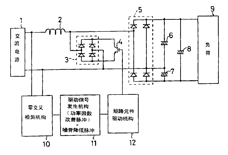
图1是本发明一实施例电源装置的电路构造图。FIG. 1 is a circuit configuration diagram of a power supply device according to an embodiment of the present invention.
图2表示图1所示电源装置各部的信号波形。FIG. 2 shows signal waveforms of various parts of the power supply unit shown in FIG. 1 .
图3表示本发明第2实施例电源装置各部的信号波形。Fig. 3 shows signal waveforms of each part of the power supply device according to the second embodiment of the present invention.
图4是本发明第3实施例电源装置的电路构造的图。Fig. 4 is a diagram showing a circuit configuration of a power supply unit according to a third embodiment of the present invention.
图5表示本发明第4实施例电源装置各部的信号波形。Fig. 5 shows signal waveforms of each part of the power supply device according to the fourth embodiment of the present invention.
图6表示本发明第5实施例电源装置各部的信号波形。Fig. 6 shows signal waveforms of each part of the power supply device according to the fifth embodiment of the present invention.
图7是说明产生功率因数改善脉冲及噪音降低脉冲的驱动信号发生机构的构造的图。FIG. 7 is a diagram illustrating the structure of a drive signal generating mechanism for generating power factor improvement pulses and noise reduction pulses.
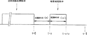
图8表示功率因数改善脉冲与噪音降低脉冲之间的间歇时间及噪音降低脉冲的短路时间。FIG. 8 shows the intermittent time between the power factor improvement pulse and the noise reduction pulse and the short-circuit time of the noise reduction pulse.
图9表示噪音降低脉冲为1个、2个、n个时的功率因数改善脉冲及噪音脉冲降低脉冲之间的间歇时间及噪音降低脉冲的短路时间。FIG. 9 shows the power factor improvement pulse and the pause time between the noise reduction pulses and the short-circuit time of the noise reduction pulse when there are 1, 2, and n noise reduction pulses.
图10表示第i个噪音降低脉冲的上升及下降时刻的定义。FIG. 10 shows the definitions of the rising and falling timings of the i-th noise reduction pulse.
图11是表示噪音降低脉冲为2个时的功率因数改善脉冲、间歇时间、短路时间的关系。FIG. 11 shows the relationship among power factor improvement pulses, pause time, and short-circuit time when there are two noise reduction pulses.
图12表示相对于短路元件驱动机构的延迟、短路元件的接通延迟时间及切断延迟时间,对间歇时间及短路时间修正方法。FIG. 12 shows how to correct the intermittent time and the short-circuit time with respect to the delay of the short-circuit element driving mechanism, the on-delay time and the off-delay time of the short-circuit element.
图13表示将本发明的电源装置用于空气调节装置时的构造。Fig. 13 shows the configuration when the power supply unit of the present invention is used in an air conditioner.
图14是表示内装有本发明电源装置的空气调节装置和内装有无噪音降低功能的现有电源装置的空气调节装置的噪音特性曲线。Fig. 14 is a graph showing noise characteristics of an air conditioner incorporating a power supply unit of the present invention and an air conditioner incorporating a conventional power supply unit without a noise reduction function.
下面,参照附图说明本发明的实施例。Embodiments of the present invention will be described below with reference to the drawings.
图1是本发明一实施例电源装置的电路构造图。图2表示图1所示电源装置的各部的信号波形。图1所示的电源装置,具有一端与交流电源1的一个输出端连接的电抗线圈2,该电抗线圈2的另一端分别与第1二极管电桥3和第2二极管电桥5的各一方输入端连接,第1二极管电桥3由4个二极管构成,其电流方向一致,第2二极管电桥5构成全波整流器。第1和第2二极管电桥3、5的各另一方输入端与交流电源1的另一个输出端连接。FIG. 1 is a circuit configuration diagram of a power supply device according to an embodiment of the present invention. FIG. 2 shows signal waveforms of various parts of the power supply device shown in FIG. 1 . The power supply device shown in FIG. 1 has a
第1二极管电桥3的两输出端连接在短路元件4的整流子与发射极之间,该短路元件4例如是由双极晶体管、IGBT、MOSFET等构成的开关元件,当短路元件4接通时,通过第1二极管电桥3和电抗线圈2将交流电源1短路,以此能改善电源装置的电源功率因数。短路元件4的门与短路元件驱动机构12连接,由该短路元件驱动机构12驱动短路元件4,使短路元件4成为接通状态。The two output terminals of the
交流电源1的两输出端连接着例如由光耦合器、变流器等构成的零交叉检测机构10,该零交叉检测机构10检测出交流电源1的交流电压、即具有图2中标号21所示正弦波形的交流电压通过零点即零交叉点的时刻,把该检测信号供给驱动信号发生机构11。The two output terminals of the
驱动信号发生机构11例如由微型计算机、专用电路等构成,产生如图2中的标号24a及26a分别所示的功率因数改善脉冲和脉宽比该功率因数改善脉冲小得多的噪音降低脉冲,把这些功率因数改善脉冲24a及噪音降低脉冲26a供给短路元件驱动机构12。短路元件驱动机构12应答这些功率因数改善脉冲24a和噪音降减脉冲26a,将短路元件4驱动成为接通状态,这样,通过第1二极管电桥3和电抗线圈2使交流电源1短路。其结果,当功率因数改善脉冲24a使短路元件4接通时,通过第1二极管电桥3和电抗线圈2将交流电源1短路,可改善电源功率因数,同时,噪音降低脉冲26a使短路元件4接通时,可降低为了改善电源功率因数而电抗线圈2短路时产生的噪音。Drive
第2二极管电桥5的输出端通过平滑用电解电容6、7、8与负荷9连接,这样,来自交流电源1的交流电压被第2二极管电桥5及平滑用电解电容6、7、8倍电压整流后,作为直流电压供给负荷9。The output end of the
上述构造的电源装置中,当交流电源1供给了图2中标号21所示的交流电压时,该交流电压通过电抗线圈2供给由第2二极管电桥5及平滑用电解电容6、7、8构成的倍电压整流电路,作为直流电压供给负荷9,同时,该交流电压通过零点时,该零点通过由零交叉检测机构10检测出,驱动信号发生机构11被该检测信号驱动。In the power supply unit with the above structure, when the
驱动信号发生机构11被零交叉检测机构10的零点检测输出信号驱动时,交流电源的零点通过后,产生图2所示的功率因数改善脉冲24a及噪音降低脉冲26a。功率因数改善脉冲24a及噪音降低脉冲26a通过短路元件驱动机构12将短路元件4驱动成为接通状态,这样,通过第1二极管电桥3和电抗线圈2将交流电源1短路。其结果,当短路元件4应答功率因数改善脉冲24a并通过电抗线圈2将交流电源1短路时,扩大电源电流的导通期间,改善电源装置的电源功率因数,另外,短路元件4应答噪音降低脉冲26a动作时,可以降低电抗线圈2的噪音。该噪音是电抗线圈2被功率因数改善脉冲24a短路后,电抗线圈2的短路解除,短路电流切断时的噪音。When the
具体地说,如图2所示,标号22表示功率因数改善前的电源电流波形,标号23表示由功率因数改善脉冲24a改善了功率因数后的电源电流波形,由此可见,改善后的电源电流的导通期间扩大,所以,电源功率因数得到改善。在功率因数改善脉冲24a之后,紧接着输出脉宽非常小的噪音降低脉冲26a,使短路元件4短路,这样,电抗线圈2被功率因数改善脉冲24a短路时,短路电流切断时的电抗线圈的噪音可被降低,而电源电流的波形及电源功率因数几乎不变。Specifically, as shown in Fig. 2,
图3表示本发明第2实施例电源装置的各部信号波形。第2实施例与上述第1实施例的不同点仅仅是功率因数改善脉冲24a及噪音降低脉冲26a的顺序相反,其它构造及作用均与第1实施例相同。Fig. 3 shows signal waveforms of each part of the power supply device according to the second embodiment of the present invention. The difference between the second embodiment and the above-mentioned first embodiment is only that the order of the power
第2实施例的电路构造与图1所示基本相同,但从驱动信号发生机构11发生的功率因数改善脉冲24a及噪音降低脉冲26a的发生顺序相反,即如图3所示,先发生短期间的噪音降低脉冲26a,再发生功率因数改善脉冲24a。另外,在图3的信号波形图中,与图2同样地,标号21及22分别表示交流电源1的交流电源1的交流电压波形和功率因数改善前的电流波形,标号25表示进行功率因数改善及噪音改善后的电流波形。The circuit structure of the second embodiment is basically the same as that shown in FIG. 1, but the generation order of the power
第2实施例中,使噪音降低脉冲26a在功率因数改善脉冲24a之前发生,在由功率因数改善脉冲24a通过电抗线圈2将交流电源1短路之前,先由噪音降低脉冲26a使电抗线圈2瞬间短路,可降低电抗线圈2的短路电流切断时的噪音。然后再由功率因数改善脉冲24a通过电抗线圈2将交流电源1短路,这样,如图3的标号25所示,扩大电源电流的导通期间,可改善电源功率因数。In the second embodiment, the
图1至图3所示的第1及第2实施例中,使噪音降低脉冲26a在功率因数改善脉冲24a之前或之后发生,这样,通过电抗线圈2将交流电源1短路,可以降低电抗线圈2的短路电流切断或接通时的噪音。如果在功率因数改善脉冲24a之前和之后都发生噪音降低脉冲26a,则更能降低电抗线圈2的短路电流切断和接通时的噪音。In the first and second embodiments shown in FIGS. 1 to 3, the
图4表示本发明第3实施例电源装置的电路构造。该图所示的电源装置中,构成全波整流器的第2二极管电桥5的一方输出端连接着电抗线圈2的一端,在电抗线圈2的另一端与第2二极管电桥5的另一方输出端之间,连接着由开关晶体管构成的短路元件4的整流子和发射极,该短路元件4接通时,通过电抗线圈2和第2二极管电桥5将交流电源1短路。电抗线圈2的另一端通过防倒流用二极管13与平滑用电解电容8及负荷9连接。二极管13的作用是,当短路元件4接通、通过电抗线圈2及第2二极管电桥5将交流电源1短路时,使平滑用电解电容8被短路元件4短路。Fig. 4 shows a circuit configuration of a power supply unit according to a third embodiment of the present invention. In the power supply device shown in this figure, one output end of the
连接在交流电源1两输出端的零交叉检测机构10、驱动信号发生机构11、短路元件驱动机构12的构造及作用,与图1所示的相同,如图2所示,驱动信号发生机构11发生功率因数改善脉冲24a及紧接着该功率因数改善脉冲24a的噪音降低脉冲26a,这此脉冲使得通过短路元件驱动机构12将短路元件4驱动成为接通状态,由此,与第1实施例同样地,可由功率因数改善脉冲24a改善电源功率因数,由噪音降低脉冲26a降低电抗线圈2的短路电流切断时的噪音。另外,改变该功率因数脉冲24a和噪音降低脉冲26a的顺序,如图3所示地,驱动信号发生机构11先发生噪音降低脉冲26a后,再发生功率因数改善脉冲24a,这些脉冲使得通过短路元件驱动机构12将短路元件4驱动成为接通状态,与第2实施例同样地,可由噪音降低脉冲26a降低电抗线圈2的短路电流切断时的噪音,再由功率因数改善脉冲改善电源功率因数。The structure and function of the zero-
图5表示本发明第4实施例电源装置的各部信号波形。该第4实施例与上述第1实施例的不同点仅仅是在功率因数改善脉冲24a之后发生若干个(本实施例中是2个)噪音降低脉冲26a、26b。其它构造及作用与第1实施例相同。即,图5中,标号21、22分别表示交流电源1的交流电压的波形及功率因数改善前的电流波形,27表示进行了功率因数改善及噪音改善后的电流波形,24a表示功率因数改善脉冲,26a、26b表示噪音降低脉冲。Fig. 5 shows signal waveforms of each part of the power supply device according to the fourth embodiment of the present invention. The fourth embodiment differs from the first embodiment above only in that several (two in this embodiment)
第4实施例的电源装置电路构造与图1或图4所示基本相同,不同点是由驱动信号发生机构11在功率因数改善脉冲24a之后发生若干个噪音降低脉冲26a、26b。The circuit structure of the power supply device of the fourth embodiment is basically the same as that shown in Fig. 1 or Fig. 4, except that the driving
第4实施例中,在功率因数改善脉冲24a之后发生若干个噪音降低脉冲26a、26b,由功率因数改善脉冲24a改善了功率因数后,能更加切实地降低电抗线圈2的短路电流切断时产生的噪音。另外,也可以改变以上顺序,即,如图3所示地,在功率因数改善脉冲24a之前发生若干个噪音降低脉冲26a、26b,这时,能降低电抗线圈2的短路电流接通时的噪音。In the fourth embodiment, several
第4实施例中,即使发生若干个噪音降低脉冲26a、26b,这些噪音降低脉冲与功率因数改善脉冲24a相比,其脉冲宽度极短,所以,电源装置的电流波形几乎不变,对功率因数也没有影响。In the fourth embodiment, even if several
图6表示本发明第5实施例电源装置的各部信号波形。第5实施例中,发生连续若干个功率因数改善脉冲24a、24b的同时,在每一个功率因数改善脉冲之后,各发生噪音降低脉冲26a、26b。图6中,表示功率因数改善脉冲24a、24b及噪音降低脉冲26a、26b分别为2个时的情形。Fig. 6 shows signal waveforms of each part of the power supply device according to the fifth embodiment of the present invention. In the fifth embodiment, while a plurality of power
在发生连续的功率因数改善脉冲24a、24b的同时,紧接着每个功率因数改善脉冲24a、24b之后,发生一个噪音降低脉冲26a、26b,这样,在改善电源装置的功率因数的同时,可切实降低电抗线圈2的短路电流切断时的噪音。图6所示的第5实施例中,是在若干个功率因数改善脉冲的每一个之后发生一个降低噪音脉冲,但也可以在若干个功率因数改善脉冲的每一个之前发生一个噪音降低脉冲,这样,也能改善电源装置的功率因数,同时能降低电抗线圈2的电流接通时的噪音。While successive power
图6所示的第5实施例中,是相应于每一个功率因数改善脉冲发生一个噪音降低脉冲,但也可以相应于每一个功率因数改善脉冲发生若干个噪音降低脉冲26b,这种情况下,噪音降低脉冲可以在功率因数改善脉冲之前或之后发生,也可以在功率因数改善脉冲之前和之后都发生。在功率因数改善脉冲之前和之后都发生噪音降低脉冲时,可切实地降低电抗线圈2的短路电流在接通时和切断时的噪音。In the fifth embodiment shown in Fig. 6, one noise reduction pulse 26b is generated corresponding to each power factor improvement pulse, but it is also possible to generate several noise reduction pulses 26b corresponding to each power factor improvement pulse. In this case, The noise reduction pulse can occur before or after the power factor improvement pulse, or both before and after the power factor improvement pulse. When the noise reduction pulse occurs before and after the power factor improvement pulse, the noise of the short-circuit current of the
下面,参照图7说明发生功率因数改善脉冲24a和噪音降低脉冲26a的驱动信号发生机构11。为了降低电抗线圈2的振动引起的噪音,通过短路元件4使电抗线圈2短路的噪音降低脉冲26a,与为了改善电源装置功率因数而通过短路元件4使电抗线圈2短路的功率因数改善脉冲24a相比,是脉冲宽度极短、基本上不改变电流波形,对功率因数也没有影响的时间宽度的脉冲。Next, the
驱动信号发生机构11,例如可采用装在微型计算机内的定时功能的构造,或者,也可以由专用的波形生成电路构成。图7中,说明采用计数器、比较器、4个寄存器A、B、C、D时的动作。4个寄存器分别存储各脉冲间的期间及各脉冲的宽度。具体地说,从零交叉检测机构10输出的零交叉发生时刻到功率因数改善脉冲24a发生的期间,作为D1存储在寄存器A内。在D1上加上功率因数改善脉冲24a的脉冲宽度得到的值,作为D2存储在寄存器B内。在D2上加上功率因数改善脉冲24a与噪音降低脉冲26a之间的间歇期间得到的值,作为D3存储在寄存器C内。在D3上加上噪音降低脉冲26a的脉冲宽度得到的值,作为D4存储在寄存器D内。The driving signal generating means 11 may be configured by, for example, a timing function incorporated in a microcomputer, or may be constituted by a dedicated waveform generating circuit. In FIG. 7, the operation when using a counter, a comparator, and four registers A, B, C, and D is explained. The 4 registers store the period between each pulse and the width of each pulse respectively. Specifically, the period from the zero-cross occurrence time output from the zero-cross detection means 10 to the generation of the power
在零交叉检测机构10输出的零交叉发生时刻,使零交叉中断,起动计数器,将该计数器的值与各寄存器的值用比较器比较,当计数器的值达到寄存器A内存储的值D1时,发生功率因数改善脉冲24a,当计数器的值达到寄存器B内存储的值D2时,停止功率因数改善脉冲24a,当计数器的值达到寄存器C内存储的值D3时,发生噪音降低脉冲26a,当计数器的值达到寄存器D内存储的值D4时,停止噪音降低脉冲26a。通过适当设定各寄存器的值,可以简单而切实在发生具有所需脉冲宽度及间歇期间的功率因数改善脉冲24a和噪音降低脉冲26a。At the zero-cross occurrence time output by the zero-
图7中,是在发生功率因数改善脉冲24a之后再发生噪音降低脉冲26a的,但也可以通过变更各寄存器的值,简单地在功率因数改善脉冲24a之前发生噪音降低脉冲26a。另外,通过增加寄存器数目、或者不增加寄存器数目而是通过依次改写一个寄存器的值,也可以发生若干个功率因数改善脉冲和若干个噪音降低脉冲,或者相应于每一个功率因数改善脉冲发生一个或若干个噪音降低脉冲。In FIG. 7, the
下面,参照图8至图11,详细说明功率因数改善脉冲与噪音降低脉冲之间的间歇期间和噪音降低脉冲的脉冲宽度、即电抗线圈2的短路时间。Next, the intermittent period between the power factor improvement pulse and the noise reduction pulse, the pulse width of the noise reduction pulse, that is, the short-circuit time of the
电抗线圈2的噪音产生原因,是由于电流急剧地接通、切断时,使电抗线圈振动,电抗线圈以固有频率振动的缘故。在电流升高和降低时,产生相反方向的力。所以,电抗线圈的振动以T=1ms的程度继续着。The noise of the
先参照图8和图9的噪音降低脉冲数=1,说明噪音降低脉冲为一个时的情形。如图8所示,设功率因数改善脉冲的终了时刻为t=0,到噪音降低脉冲发生之间的间歇时间为x,噪音降低脉冲的短路时间为y,电抗线圈的固有频率为f,角频率ω=2πf,则电流接通、切断时电抗线圈产生的振动如下式所示。Referring first to Fig. 8 and Fig. 9 where the number of noise reduction pulses = 1, the situation when there is one noise reduction pulse will be described. As shown in Figure 8, let the end time of the power factor improvement pulse be t=0, the intermittent time between the generation of the noise reduction pulse be x, the short-circuit time of the noise reduction pulse be y, the natural frequency of the reactance coil be f, and the angle Frequency ω=2πf, then the vibration generated by the reactance coil when the current is turned on and off is shown in the following formula.
〔式1〕
t=0时产生的振动为 sin(ωt)The vibration generated when t=0 is sin(ωt)
t=x时产生的振动为 sin(ω(t-x)-π)The vibration generated when t=x is sin(ω(t-x)-π)
t=x+y时产生的振动为 sin(ω(t-x-y))The vibration generated when t=x+y is sin(ω(t-x-y))
电抗线圈的振动的实效值,在t=0~T之间如所下所示。The effective value of the vibration of the reactor coil is as follows between t=0 and T.
〔式2〕
〔式3〕[Formula 3]
F(t)=sin(ωt)+sin(ω(t-x)-π)+sin(ω(t-x-y))F(t)=sin(ωt)+sin(ω(t-x)-π)+sin(ω(t-x-y))
电抗线圈的振动的实效值的最小值,可从上式的Veff求得,但简单地只要满足F(t)=0即可。从该式计算振动的最小值时,如图9的噪音降低脉冲数=1时所示,功率因数改善脉冲与噪音降低脉冲之间的间歇时间x和噪音降低脉冲的短路时间y分别为The minimum value of the effective value of the vibration of the reactance coil can be obtained from V eff in the above formula, but it is only necessary to satisfy F(t)=0. When the minimum value of vibration is calculated from this formula, as shown in Fig. 9 when the number of noise reduction pulses = 1, the intermittent time x between the power factor improvement pulse and the noise reduction pulse and the short-circuit time y of the noise reduction pulse are respectively
x=y=π/(3ω)。x=y=π/(3ω).
在以上的说明中,对间歇时间与短路时间相等的情形作了说明,由于电抗线圈的振动是周期函数,所以,间歇时间和短路时间各自的相位即使错开2aπ/ω(a=0、1、2、3…)及2bπ/ω(b=0、1、2、3…),也能实现同样的效果,间歇时间x和短路时间y分别如下式所示即可。In the above description, the situation that the intermittent time and the short-circuit time are equal has been explained. Since the vibration of the reactor coil is a periodic function, even if the respective phases of the intermittent time and the short-circuit time are staggered by 2aπ/ω (a=0, 1, 2, 3...) and 2bπ/ω (b=0, 1, 2, 3...), the same effect can also be achieved, and the intermittent time x and the short-circuit time y are as shown in the following formulas.
x=±π/(3ω)+2aπ/ωx=±π/(3ω)+2aπ/ω
y=±π/(3ω)+2bπ/ωy=±π/(3ω)+2bπ/ω
这时,x>0,y>0,a、b可以是不同的值。但是,当间歇时间x的式中第1项的符号为+时,短路时间y的式中第1项的符号为+,反之,当间歇时间x的式中第1项的符号为-时,短路时间y的式中第1项的符号为也为-。At this time, x>0, y>0, and a and b may have different values. However, when the symbol of the first item in the formula of intermittent time x is +, the symbol of the first item in the formula of short-circuit time y is +, conversely, when the symbol of the first item in the formula of intermittent time x is -, The symbol of the first item in the formula of short-circuit time y is also -.
上面对噪音降低脉冲为一个时的情形作了说明。下面说明噪音降低脉冲为n个(n=1、2、3…)时的情形。比照上述电抗线圈振动的实效值F(t)表示一般式,如图10所示地进行噪音降低脉冲发生时刻的显示。即,以功率因数改善脉冲的终了时刻作为基准时刻(t=0),设第i个噪音降低脉冲上升和下降时刻分别为αi、βi,则0~T之间的电抗线圈振动的实效值如下式所示。The above has explained the case where the number of noise reduction pulses is one. Next, the case where there are n noise reduction pulses (n=1, 2, 3...) will be described. The general expression is expressed by comparing the effective value F(t) of the above-mentioned reactance coil vibration, and the display of the noise reduction pulse generation time is performed as shown in FIG. 10 . That is, taking the end time of the power factor improvement pulse as the reference time (t=0), assuming the rise and fall times of the i-th noise reduction pulse are respectively αi and βi, then the effective value of the reactor coil vibration between 0 and T is as follows shown in the formula.
〔式4〕
G(t)=sin(ωt)G(t)=sin(ωt)
〔式5〕
电抗线圈振动的实效值的最小值G(t)=0即可,满足该G(t)=0的αi、βi的关系有很多,作为一例,如图9所示,间歇时间x和短路时间y相等,噪音降低脉冲数n=2时,如下式所示。The minimum value G(t)=0 of the effective value of the reactance coil vibration is sufficient. There are many relationships between αi and βi that satisfy this G(t)=0. As an example, as shown in FIG. 9, the intermittent time x and the short-circuit time When y is equal, the number of noise reduction pulses n=2, as shown in the following formula.
xi=yi=π/5(ω)xi=yi=π/5(ω)
同样地,相等的噪音降低脉冲为n(n=1、2、3…)个时,如下式所示。Similarly, when there are n (n=1, 2, 3, . . . ) equal noise reduction pulses, it is as shown in the following formula.
xi=yi=π/((2n+1)ω)xi=yi=π/((2n+1)ω)
从周期函数的性质考虑,当相位错开2aπ/ω(a=0、1、2、3…)时,如下式所示。Considering the nature of the periodic function, when the phase is staggered by 2aπ/ω (a=0, 1, 2, 3...), it is shown in the following formula.
〔式6〕[Formula 6]
xi=yi=π/((2n+1)ω)+2aπ/ωxi=yi=π/((2n+1)ω)+2aπ/ω
作为另一例,当n=2时,也能容易地想象出图11所示的噪音降低脉冲,它们也包含在满足上述G(t)=0的关系中。另外,其它的满足G(t)=0的条件也存在,其说明从略。As another example, when n=2, noise reduction pulses shown in FIG. 11 can also be easily imagined, and they are also included in the relationship satisfying the above-mentioned G(t)=0. In addition, other conditions satisfying G(t)=0 also exist, and their descriptions are omitted.
如上所述,通过根据电抗线圈的固有频率决定噪音降低脉冲的间歇时间x和短路时间y,可以最有效地降低电抗线圈的噪音。该决定方法不因电源频率、负荷等的状态而改变最适当条件。决定了所用的电抗线圈后,决定固有频率,可决定最适当的噪音降低脉冲。As described above, by determining the intermittent time x and the short-circuit time y of the noise reduction pulse according to the natural frequency of the reactor coil, the noise of the reactor coil can be reduced most effectively. This determination method does not change the optimum conditions depending on the state of power supply frequency, load, etc. After determining the reactance coil to be used, the natural frequency can be determined to determine the most appropriate noise reduction pulse.
下面,参照图12说明相对于短路元件驱动机构12的延迟、短路元件4的接通时间延迟及切断时间延迟,对上述决定的间歇时间及短路时间进行修正的方法。图12中表示在短路元件驱动机构12和短路元件4中,假设切断时间比接通时间快进行修正的情形。Next, a method of correcting the above-determined intermittent time and short-circuit time with respect to the delay of the short-circuit
为了使噪音成为最小值地决定短路元件4的电流的通/断定时,驱动信号发生机构11的输出信号把间歇时间设定得短,仅相当于短路元件驱动机构12和短路元件4的延迟时间,把噪音降低脉冲的短路时间设定得长。这样,能以上述计算得到的通/断定时使短路元件4动作。另外,在图12中,把短路元件4的电流波形简单地表示为矩形波。在图12中,是在输出了功率因数改善脉冲之后再发生噪音降低脉冲的,但是,如果在输出功率因数改善脉冲之前发生噪音降低脉冲,通过进行同样的修正,也可以降低电抗线圈的噪音。另外,噪音降低脉冲有若干个时,通过进行同样的修正,也可以防止电抗线圈的噪音。In order to minimize the noise and determine the on/off of the current of the short-circuit element 4, the output signal of the drive
下面参照图13,说明将本发明的电源装置用于空气调节装置时的情形。图13中,交流电源1、电抗线圈2、第1二极管电桥3、短路元件4、第2二极管电桥5、平滑用电解电容6、7、8、零交叉检测机构10、短路元件驱动机构12与图1所示电源装置中的相同。15是微型计算机,16是倒相电路,17是压缩机用马达。Next, referring to Fig. 13, a description will be given of the case where the power supply unit of the present invention is used in an air conditioner. In Fig. 13, an
微型计算机15控制倒相电路16并使压缩机用马达17运转,进行整个空气调节装置的控制,同时,接受来自零交叉检测机构10的零交叉检测输出信号,进行与驱动信号发生机构11同等的动作,发生上述的功率因数改善脉冲和噪音降低脉冲,把这些脉冲供给短路元件驱动机构12,通过该短路元件驱动机构12驱动短路元件4,这样,通过电抗线圈2和第1二极管电桥3将交流电源1短路,改善电源装置的功率因数,同时降低电抗线圈的噪音。The
图14是噪音特性曲线图,表示内装着具有功率因数改善功能及噪音降低功能的本发明电源装置的空气调节装置、以及内装着只有功率因数改善功能而没有噪音降低功能的现有电源装置的空气调节装置的噪音特性。图中,曲线Y表示内装着现有电源装置的空气调节装置的噪音特性,曲线H表示内装着本发明电源装置的空气调节装置的噪音特性。从图中可见,曲线Y中的7KHz至8KHz区间的噪音很大,而曲线H中的7KHz至8KHz区间的噪音减低了很多。Fig. 14 is a noise characteristic graph showing an air conditioner incorporating a power supply unit of the present invention having a power factor improvement function and a noise reduction function, and an air conditioning unit incorporating a conventional power supply unit having only a power factor improvement function but no noise reduction function. Adjust the noise characteristics of the device. In the figure, curve Y represents the noise characteristic of the air conditioner incorporating the conventional power supply unit, and curve H represents the noise characteristic of the air conditioner incorporating the power supply unit of the present invention. It can be seen from the figure that the noise in the interval from 7KHz to 8KHz in curve Y is very large, while the noise in the interval from 7KHz to 8KHz in curve H is much reduced.
Claims (14)
Applications Claiming Priority (3)
| Application Number | Priority Date | Filing Date | Title |
|---|---|---|---|
| JP230958/96 | 1996-08-30 | ||
| JP23095896A JP3578874B2 (en) | 1996-08-30 | 1996-08-30 | Power supply and power supply for air conditioner |
| JP230958/1996 | 1996-08-30 |
Publications (2)
| Publication Number | Publication Date |
|---|---|
| CN1175813A true CN1175813A (en) | 1998-03-11 |
| CN1067500C CN1067500C (en) | 2001-06-20 |
Family
ID=16915996
Family Applications (1)
| Application Number | Title | Priority Date | Filing Date |
|---|---|---|---|
| CN97115283A Expired - Fee Related CN1067500C (en) | 1996-08-30 | 1997-08-29 | Power supply unit |
Country Status (4)
| Country | Link |
|---|---|
| JP (1) | JP3578874B2 (en) |
| KR (1) | KR100266034B1 (en) |
| CN (1) | CN1067500C (en) |
| GB (1) | GB2316817B (en) |
Cited By (4)
| Publication number | Priority date | Publication date | Assignee | Title |
|---|---|---|---|---|
| CN101080864B (en) * | 2004-12-15 | 2010-06-23 | 富士通将军股份有限公司 | Power supply device |
| CN102055350A (en) * | 2009-11-06 | 2011-05-11 | 日立空调·家用电器株式会社 | DC power supply device and air-conditioner using the same |
| CN102095922A (en) * | 2010-11-28 | 2011-06-15 | 沈阳工业大学 | A Method for Predicting the Zero Point of Short Circuit Current |
| CN101622778B (en) * | 2007-12-27 | 2013-03-20 | 东芝开利株式会社 | DC power supply device |
Families Citing this family (10)
| Publication number | Priority date | Publication date | Assignee | Title |
|---|---|---|---|---|
| GB2335550B (en) * | 1997-06-27 | 1999-12-22 | Toshiba Kk | Direct-current power supply system and air conditioner using such power supply system |
| JP3550485B2 (en) * | 1997-06-27 | 2004-08-04 | 東芝キヤリア株式会社 | DC power supply and air conditioner |
| TW364049B (en) | 1997-09-24 | 1999-07-11 | Toshiba Corp | Power conversion apparatus and air conditioner using the same |
| KR100321244B1 (en) * | 1998-12-30 | 2002-03-08 | 윤종용 | Harmonic Suppression Device of Air Conditioner and Its Suppression Method |
| US6281658B1 (en) * | 1999-01-08 | 2001-08-28 | Lg Electronics Inc. | Power factor compensation device for motor driving inverter system |
| KR100420964B1 (en) * | 2002-02-23 | 2004-03-02 | 학교법인 포항공과대학교 | Single-stage converter compensating power factor |
| KR100757484B1 (en) * | 2002-03-08 | 2007-09-11 | 주식회사 엘지이아이 | Power Factor Correction Control Circuit and Method of Inverter Air Conditioner |
| KR100614330B1 (en) * | 2004-02-24 | 2006-08-18 | 엘지전자 주식회사 | Power factor improvement method of inverter control circuit |
| WO2016051488A1 (en) * | 2014-09-30 | 2016-04-07 | 三菱電機株式会社 | Power conversion device |
| JP2018174643A (en) * | 2017-03-31 | 2018-11-08 | 三菱重工サーマルシステムズ株式会社 | CONVERTER DEVICE, ITS CONTROL METHOD, AND MOTOR DRIVE DEVICE |
Family Cites Families (6)
| Publication number | Priority date | Publication date | Assignee | Title |
|---|---|---|---|---|
| JPS61224857A (en) * | 1985-03-29 | 1986-10-06 | Hitachi Ltd | Controller of rectifier circuit |
| JPH02299470A (en) * | 1989-05-11 | 1990-12-11 | Fuji Electric Co Ltd | High power-factor rectifier circuit |
| WO1993026078A1 (en) * | 1992-06-10 | 1993-12-23 | Digital Equipment Corporation | High power factor switched dc power supply |
| JP2763479B2 (en) * | 1992-08-06 | 1998-06-11 | 三菱電機株式会社 | DC power supply |
| JP2739706B2 (en) * | 1993-09-17 | 1998-04-15 | 東光株式会社 | AC-DC converter |
| EP1300937B1 (en) * | 1994-07-01 | 2010-06-09 | Sharp Kabushiki Kaisha | Air conditioning device |
-
1996
- 1996-08-30 JP JP23095896A patent/JP3578874B2/en not_active Expired - Fee Related
-
1997
- 1997-08-18 KR KR1019970039765A patent/KR100266034B1/en not_active Expired - Fee Related
- 1997-08-29 GB GB9718368A patent/GB2316817B/en not_active Expired - Fee Related
- 1997-08-29 CN CN97115283A patent/CN1067500C/en not_active Expired - Fee Related
Cited By (6)
| Publication number | Priority date | Publication date | Assignee | Title |
|---|---|---|---|---|
| CN101080864B (en) * | 2004-12-15 | 2010-06-23 | 富士通将军股份有限公司 | Power supply device |
| CN101622778B (en) * | 2007-12-27 | 2013-03-20 | 东芝开利株式会社 | DC power supply device |
| CN102055350A (en) * | 2009-11-06 | 2011-05-11 | 日立空调·家用电器株式会社 | DC power supply device and air-conditioner using the same |
| CN102055350B (en) * | 2009-11-06 | 2014-04-02 | 日立空调·家用电器株式会社 | DC power supply device and air-conditioner using the same |
| CN102095922A (en) * | 2010-11-28 | 2011-06-15 | 沈阳工业大学 | A Method for Predicting the Zero Point of Short Circuit Current |
| CN102095922B (en) * | 2010-11-28 | 2012-12-12 | 沈阳工业大学 | Short circuit current zero predicting method |
Also Published As
| Publication number | Publication date |
|---|---|
| CN1067500C (en) | 2001-06-20 |
| GB2316817B (en) | 1998-09-23 |
| KR100266034B1 (en) | 2000-09-15 |
| JPH1080139A (en) | 1998-03-24 |
| KR19980018826A (en) | 1998-06-05 |
| GB9718368D0 (en) | 1997-11-05 |
| GB2316817A (en) | 1998-03-04 |
| JP3578874B2 (en) | 2004-10-20 |
Similar Documents
| Publication | Publication Date | Title |
|---|---|---|
| CN1067500C (en) | Power supply unit | |
| CN1246954C (en) | Switch type power source | |
| CN1060298C (en) | Interleaved switching converter circuit and switching converter controlling method | |
| CN1161678C (en) | Solar generating device | |
| CN1182651C (en) | DC brushless motor drive device and air conditioner using same | |
| CN1229605C (en) | Inverter air conditioner | |
| CN1050475C (en) | Power generating equipment for vehicle | |
| CN1726631A (en) | Switching power supply device and method for controlling switching power supply device | |
| CN1120565C (en) | Method and circuit for resonance inversion | |
| CN1538584A (en) | Motor control equipment | |
| CN101079576A (en) | System and method for switch of power adjuster | |
| CN1639954A (en) | Switching power source apparatus | |
| CN1357964A (en) | DC-DC converter | |
| CN1018413B (en) | Pulse Width Modulation Type Inverter | |
| CN1538611A (en) | Inverter controllers for driving motors and air conditioners using inverter controllers | |
| CN1360392A (en) | Noise reducing device for electric power conversion device | |
| CN1830134A (en) | Load driver capable of suppressing overcurrent | |
| CN1719710A (en) | power circuit | |
| CN88101565A (en) | Pulse Width Modulation Power Converter | |
| CN1505256A (en) | motor drive circuit | |
| CN1770612A (en) | Semiconductor device for switching power supply control and switching power supply device using the semiconductor device | |
| CN1393989A (en) | Apparatus and method for driving motor | |
| CN1170276A (en) | Electroluminescent display device and drive circuit for display device | |
| CN1825743A (en) | LLC series resonant converter and its synchronous rectification power switch driving method | |
| CN2589870Y (en) | Frequency conversion air-conditioner |
Legal Events
| Date | Code | Title | Description |
|---|---|---|---|
| C10 | Entry into substantive examination | ||
| SE01 | Entry into force of request for substantive examination | ||
| C06 | Publication | ||
| PB01 | Publication | ||
| C14 | Grant of patent or utility model | ||
| GR01 | Patent grant | ||
| C19 | Lapse of patent right due to non-payment of the annual fee | ||
| CF01 | Termination of patent right due to non-payment of annual fee |