CN1217103C - Switchable inflator - Google Patents
Switchable inflator Download PDFInfo
- Publication number
- CN1217103C CN1217103C CN998096423A CN99809642A CN1217103C CN 1217103 C CN1217103 C CN 1217103C CN 998096423 A CN998096423 A CN 998096423A CN 99809642 A CN99809642 A CN 99809642A CN 1217103 C CN1217103 C CN 1217103C
- Authority
- CN
- China
- Prior art keywords
- battery
- fluid
- moving device
- power switch
- batteries
- Prior art date
- Legal status (The legal status is an assumption and is not a legal conclusion. Google has not performed a legal analysis and makes no representation as to the accuracy of the status listed.)
- Expired - Lifetime
Links
Images

Classifications
-
- F—MECHANICAL ENGINEERING; LIGHTING; HEATING; WEAPONS; BLASTING
- F04—POSITIVE - DISPLACEMENT MACHINES FOR LIQUIDS; PUMPS FOR LIQUIDS OR ELASTIC FLUIDS
- F04D—NON-POSITIVE-DISPLACEMENT PUMPS
- F04D25/00—Pumping installations or systems
- F04D25/02—Units comprising pumps and their driving means
- F04D25/08—Units comprising pumps and their driving means the working fluid being air, e.g. for ventilation
- F04D25/084—Units comprising pumps and their driving means the working fluid being air, e.g. for ventilation hand fans
-
- F—MECHANICAL ENGINEERING; LIGHTING; HEATING; WEAPONS; BLASTING
- F04—POSITIVE - DISPLACEMENT MACHINES FOR LIQUIDS; PUMPS FOR LIQUIDS OR ELASTIC FLUIDS
- F04D—NON-POSITIVE-DISPLACEMENT PUMPS
- F04D25/00—Pumping installations or systems
- F04D25/02—Units comprising pumps and their driving means
- F04D25/06—Units comprising pumps and their driving means the pump being electrically driven
- F04D25/0673—Battery powered
Landscapes
- Engineering & Computer Science (AREA)
- Mechanical Engineering (AREA)
- General Engineering & Computer Science (AREA)
- Battery Mounting, Suspending (AREA)
- Structures Of Non-Positive Displacement Pumps (AREA)
- Yarns And Mechanical Finishing Of Yarns Or Ropes (AREA)
- Confectionery (AREA)
- Supplying Of Containers To The Packaging Station (AREA)
- Power Steering Mechanism (AREA)
- Air Bags (AREA)
Abstract
Description
本发明的技术领域Technical Field of the Invention
这项发明涉及一种流体移动装置,该流体移动装置主要是与低压充气制品一起使用的,但不排除其他的应用。This invention relates to a fluid moving device primarily for use with low pressure inflatable articles, but not to the exclusion of other applications.
本发明的概述Summary of the invention
在一个实施方案中,本发明是一种用流体填充贮器的装置。所述装置包括为把流体引入所述装置而配备的流体入口、使流体通过所述装置为填充所述贮器提供流体的移动装置,以及把流体提供给所述贮器的流体转移孔。该装置进一步包括通过手工操作启动和关闭所述移动装置的电源开关。按照这个实施方案,该装置配备了为流体入口、移动装置,流体转移孔和电源开关提供外壳的手持机壳。该手持机壳具有这样的形状或布局,以致用单一的用户手柄就可以把它握在用户的一只手中,所述的手持机壳和单一的用户手柄允许流体转移孔通过旋转进入和退出与所述贮器咬合的状态并且还允许用户用同一只手拨动电源开关起动和关闭该装置。其中所述移动装置(11)包括调节流体压力,把加压的流体提供给并通过流体转移孔(18)的装置。其中所述手持机壳(1)可以围绕着所述装置(100)的轴线按顺时针方向和逆时针方向旋转,以进入和退出与所述贮器(28)咬合的状态。其中电源开关(5)是这样配置的,以致当所述装置(100)通过单一的用户手柄被用户握在手中时它可以与用户的手指接触,并且通过简单地移动用户的手指就可以起动和关闭所述装置(100)。其中所述电源开关(5)包括自密封的结构(6),该结构在所述电源开关(5)处于关闭位置时将流体入口(10)密封,而在电源开关(5)不处于关闭位置时不密封所述流体入口(10)。其中所述流体入口(10)包括许多凹进手持机壳(1)外壁的进气孔。其中所述电源开关(5)具有一系列与所述电源开关(5)一起移动的反向槽(7),当电源开关(5)处于关闭位置时它们将进气孔密封,当电源开关(5)不处于关闭位置时它们将不密封进气孔。其中所述移动装置(11)包括与叶轮(11)结合的马达(3),其中叶轮(11)的轮毂(9)紧靠着马达(3)轴上的轴衬,叶轮(11)的叶片面向马达,叶轮(11)的背面面对流体转移孔(18),这样在出现轴向载荷时,可以防止叶轮(11)与马达(3)脱开,并且使叶轮(11)的叶片不受任何可能通过流体转移孔(18)进入的物体的影响。其中所述装置(100)进一步包括毗邻流体转移孔(18)配置的静止的叶片(16),这些叶片把流动路径引向通过流体转移孔(18)。进一步包括电池舱(30),该电池舱具有适合与标准尺寸的电池组(33,36)实现电连接的尺寸和布局。装置(100)进一步包括按不同尺寸制造的电池的可以拆卸的电池组件(38),其中可以拆卸的电池组件(38)具有适合与所述的电池舱(30)电连接的尺寸和布局。装置(100)进一步包括永久地安装在电池舱(30)中可以再充电的电池(36)。装置(100)进一步包括可以拆卸的电池容器(50),其尺寸和布局适合使尺寸不同的电池(33,36)适应电池舱(30)的尺寸和布局,以使不同尺寸的电池(33,36)能够与电池舱(30)实现电连接。装置(100)其中所述标准尺寸的电池组(33,36)是C类型号的碱性电池(33)。其中所述的不同尺寸的电池(33,36)是可再充电的电池(36)。其中所述可以拆卸的电池容器(50)包括一条槽,这条槽允许可再充电的电池(36)与所述装置(100)的所述电池舱(30)实现电接触。其中可以拆卸的电池容器(50)包括适合使所述可以拆卸的电池容器(50)和尺寸不同的电池与电池(33,36)充电装置(72)耦合的结构。其中所述结构包括一对从可以拆卸的电池容器(50)的一端伸出的突舌(58,59),每个突舌(58,59)都具有加肋的构造,这种构造形成每个突舌(58,59)的槽形部分(64,65)。其中所述的那对突舌(58,59)的槽形部分(64,65)具有这样的尺寸和布局,以致它们通过组合与电池充电装置(72)相匹配,并且使尺寸不同的电池(33,36)的末端(80,81)与电池充电装置(72)相接触。其中可以拆卸的电池容器(50)具有这样的构造和布局,以致它可以被打开和关闭以适应尺寸不同的电池(33,36)的拆除、更换或变更位置。其中可以拆卸的电池容器(50)具有可以在内部重新排列的构造和布局,以致所述的可以拆卸的电池容器(50)能够适应许多种尺寸和类型的电池(33,36)。装置(100)中所述电池舱(30)包括至少一个弹簧(39),所述弹簧迫使可以再次充电的电池(36)与所述电池舱(30)实现电连接。装置(100)中可以拆卸的电池组件(38)和可以拆卸的电池容器(50)之一包括保证可以拆卸的电池组件(38)或可以拆卸的电池容器(50)在电池舱(30)中适当取向的装置。In one embodiment, the invention is a device for filling a reservoir with a fluid. The device includes a fluid inlet configured to introduce fluid into the device, movement means for passing fluid through the device to provide fluid for filling the reservoir, and a fluid transfer aperture for providing fluid to the reservoir. The device further includes a power switch for manually activating and deactivating the mobile device. According to this embodiment, the device is provided with a hand-held housing that provides housing for the fluid inlet, displacement device, fluid transfer port and power switch. The hand-held housing has such a shape or layout that it can be held in one hand of the user with a single user handle that allows the fluid transfer hole to be rotated into and out of the The state of the receptacle snaps in and also allows the user to activate and deactivate the device by flipping the power switch with the same hand. Wherein said moving means (11) includes means for regulating fluid pressure, supplying pressurized fluid to and through fluid transfer holes (18). Wherein the hand-held casing (1) can rotate clockwise and counterclockwise around the axis of the device (100) to enter and exit the state of engaging with the receptacle (28). Wherein the power switch (5) is configured such that when the device (100) is held in the user's hand by a single user handle it is in contact with the user's finger and can be activated and activated by simply moving the user's finger The device (100) is switched off. Wherein the power switch (5) comprises a self-sealing structure (6), which seals the fluid inlet (10) when the power switch (5) is in the off position, and seals the fluid inlet (10) when the power switch (5) is not in the off position The fluid inlet (10) is not sealed from time to time. Wherein the fluid inlet (10) includes many air intake holes recessed into the outer wall of the hand-held case (1). Wherein the power switch (5) has a series of reverse slots (7) that move together with the power switch (5), and they seal the air inlet when the power switch (5) is in the off position, when the power switch ( 5) They will not seal the air intake when not in the closed position. Wherein said moving device (11) comprises a motor (3) combined with an impeller (11), wherein the hub (9) of the impeller (11) is close to the bushing on the shaft of the motor (3), and the blades of the impeller (11) Facing the motor, the back of the impeller (11) faces the fluid transfer hole (18), so that in the event of an axial load, the impeller (11) can be prevented from being disengaged from the motor (3), and the blades of the impeller (11) will not be affected. The effect of any object that may enter through the fluid transfer hole (18). Wherein said device (100) further comprises stationary vanes (16) disposed adjacent to the fluid transfer hole (18), the vanes directing the flow path through the fluid transfer hole (18). A battery compartment (30) is further included having a size and layout suitable for electrical connection with standard sized battery packs (33, 36). The device (100) further comprises a removable battery assembly (38) of batteries manufactured in different sizes, wherein the removable battery assembly (38) has a size and layout suitable for electrical connection with said battery compartment (30). The device (100) further includes a rechargeable battery (36) permanently mounted in the battery compartment (30). The device (100) further includes a detachable battery container (50) sized and arranged to accommodate differently sized batteries (33, 36) to the size and layout of the battery compartment (30) so that differently sized batteries (33, 36) 36) It can be electrically connected with the battery compartment (30). The device (100) wherein said standard size battery pack (33, 36) is a Type C model alkaline battery (33). The batteries (33, 36) of different sizes described therein are rechargeable batteries (36). Wherein said removable battery container (50) includes a slot which allows a rechargeable battery (36) to make electrical contact with said battery compartment (30) of said device (100). Wherein the detachable battery container (50) includes structure suitable for coupling said detachable battery container (50) and batteries of different sizes with a battery (33, 36) charging device (72). Wherein the structure includes a pair of tabs (58, 59) protruding from one end of the detachable battery container (50), each tab (58, 59) having a ribbed configuration forming each grooved portion (64, 65) of a tongue (58, 59). The grooved portions (64, 65) of the pair of tabs (58, 59) described therein are sized and arranged so that they match the battery charging device (72) by combination and allow batteries of different sizes ( 33, 36) are in contact with the battery charging device (72) at their ends (80, 81). The removable battery container (50) therein has such a construction and layout that it can be opened and closed to accommodate removal, replacement or relocation of batteries (33, 36) of different sizes. Wherein the removable battery container (50) has an internally rearrangeable configuration and layout such that the removable battery container (50) can accommodate a wide variety of sizes and types of batteries (33, 36). The battery compartment (30) of the device (100) includes at least one spring (39) that urges a rechargeable battery (36) into electrical connection with the battery compartment (30). One of the detachable battery assembly (38) and the detachable battery container (50) in the device (100) includes ensuring that the detachable battery assembly (38) or the detachable battery container (50) is in the battery compartment (30) Properly oriented device.
按照本发明的另一个实施方案,提供了一种流体移动装置,该装置包括把流体引入所述的流体移动装置的流体入口、使流体通过所述的流体移动装置移动的移动装置、以及提供流体的流体转移孔。按照这个实施方案,流体移动装置配备一个电池舱,其尺寸和布局适合与标准尺寸的电池组实现电连接。此外,该流体移动装置还配备了一个可以拆卸的电池容器,该电池容器的尺寸和布局使不同尺寸的电池适应所述电池舱的尺寸或布局,以致不同尺寸的电池都能与所述的电池舱实现电连接,或者一个由不同尺寸的电池制成的可以拆卸的电池组件,该电池组件的尺寸或布局适合与所述的电池舱实现电连接。According to another embodiment of the present invention, there is provided a fluid moving device comprising a fluid inlet for introducing fluid into said fluid moving device, a moving device for moving fluid through said fluid moving device, and providing a fluid fluid transfer holes. According to this embodiment, the fluid moving device is provided with a battery compartment sized and arranged for electrical connection to a standard size battery pack. In addition, the fluid moving device is provided with a detachable battery container sized and arranged to accommodate batteries of different sizes to the size or layout of the battery compartment so that batteries of different sizes can be combined with the battery compartment for electrical connection, or a detachable battery assembly made of batteries of different sizes, the size or layout of which is suitable for electrical connection with said battery compartment.
按照本发明的第三个实施方案,提供了一种流体移动装置,该装置包括为把流体引入该流体移动装置而准备的自密封的流体入口、使流体通过该流体移动装置移动的移动装置、以及提供流体的流体转移孔。按照这个实施方案,该流体移动装置还配备了起动和关闭该移动装置的电源开关。该电源开关包括自密封的结构,当电源开关处于关闭位置时该结构将自密封的流体入口密封,当电源开关不处于关闭位置时,它不密封那个自密封的流体入口。According to a third embodiment of the present invention there is provided a fluid moving device comprising a self-sealing fluid inlet for introducing fluid into the fluid moving device, a moving device for moving fluid through the fluid moving device, and fluid transfer holes for supplying fluid. According to this embodiment, the fluid moving device is also equipped with a power switch to activate and deactivate the moving device. The power switch includes a self-sealing structure that seals the self-sealing fluid inlet when the power switch is in the off position and that does not seal the self-sealing fluid inlet when the power switch is not in the off position.
按照本发明的第四个实施方案,提供了一种电池供电的装置,该装置包括尺寸和布局适合与标准尺寸的电池组实现电连接的电池舱。按照这个实施方案,该电池供电的装置还配备一个可以拆卸的电池容器,其尺寸和布局使不同尺寸的电池适应所述电池舱的尺寸和布局,以致不同尺寸的电池都能够与所述的电池舱实现电连接;或者配备一个由不同尺寸的电池制成的可以拆卸的电池组件,该电池组件具有适合与所述的电池舱实现电连接的尺寸和布局。According to a fourth embodiment of the present invention, there is provided a battery powered device comprising a battery compartment sized and arranged for electrical connection with a standard size battery pack. According to this embodiment, the battery-powered unit is also provided with a removable battery container sized and arranged to adapt batteries of different sizes to the size and layout of said battery compartment, so that batteries of different sizes can be connected to said battery compartment. compartment for electrical connection; or a detachable battery assembly made of batteries of different sizes having dimensions and layout suitable for electrical connection with said battery compartment.
附图的简要说明Brief description of the drawings
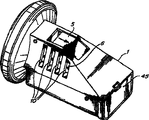
图1是手持流体移动装置的透视正视图,它表示该装置被保持在断电模式;Figure 1 is a perspective front view of a handheld fluid moving device showing that the device is held in a power-off mode;
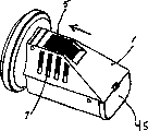
图2是流体移动装置的透视侧面图,它图解说明开关处于断电位置而换气孔处于关闭位置;Figure 2 is a perspective side view of the fluid moving device illustrating the switch in the de-energized position and the vent in the closed position;
图3是手持流体移动装置的透视正视图,它表示该装置被保持在通电模式;Figure 3 is a perspective front view of a handheld fluid moving device showing that the device is held in a powered mode;
图4是流体移动装置的透视侧视图,它表示开关处于通电位置而换气孔处于打开位置;Figure 4 is a perspective side view of the fluid moving device showing the switch in the energized position and the vent in the open position;
图5是流体移动装置的侧视截面图,它图解说明其各个组成部分的布局以及借助充气阀与充气贮器的连接;Figure 5 is a side cross-sectional view of the fluid moving device illustrating the layout of its various components and connection to the inflatable reservoir via the inflatable valve;
图6是流体移动装置的透视正视图,它表示该装置处于“准备就绪”的位置,该流体移动装置已经接通电源并且借助充气阀可以与贮器衔接或断开;Figure 6 is a perspective front view of the fluid moving device, showing the device in the "ready" position, the fluid moving device has been powered on and can be engaged or disconnected from the reservoir by means of the inflation valve;
图7是流体移动装置的俯视剖面图,其中包括电池舱的实施方案;Figure 7 is a top sectional view of a fluid moving device including an embodiment of a battery compartment;
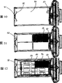
图8是流体移动装置的俯视图,它展示安装了常规电池的电池舱;Figure 8 is a top view of the fluid moving device showing the battery compartment with conventional batteries installed;
图9是流体移动装置的俯视图,它展示安装了充电电池的电池舱;Figure 9 is a top view of the fluid moving device showing the battery compartment with rechargeable batteries installed;
图10是流体移动装置的俯视图,它图解说明电池舱的另一个实施方案;Figure 10 is a top view of a fluid moving device illustrating another embodiment of a battery compartment;
图11是流体移动装置的俯视图,它图解说明图10所示电池舱安装了常规电池;Figure 11 is a top view of the fluid moving device illustrating the battery compartment shown in Figure 10 with conventional batteries installed;
图12是流体移动装置的俯视图,它图解说明图10所示的电池舱并且图解说明在电池容器内安装了充电电池的电池组件被放置在电池舱内;12 is a top view of the fluid moving device illustrating the battery compartment shown in FIG. 10 and illustrating the placement of a battery assembly with rechargeable batteries installed in the battery container within the battery compartment;
图13是图12所示的电池容器和包括充电电池的电池组件以及本发明的电池充电适配器的透视图;13 is a perspective view of the battery container shown in FIG. 12 and the battery assembly including the rechargeable battery and the battery charging adapter of the present invention;
图14是图13所示的电池充电适配器的透视图;Figure 14 is a perspective view of the battery charging adapter shown in Figure 13;
图15是图13所示的电池容器,电池组件和电池充电适配器的透视图,它们图解说明电池充电适配器与电池组件和电池容器的连接;Figure 15 is a perspective view of the battery container, battery pack and battery charging adapter shown in Figure 13 illustrating the connection of the battery charging adapter to the battery pack and battery container;
图16是具有电源开关的流体移动装置的侧面剖开的透视图,它展示在安装了常规电池的情况下装置内部各个组成部分的布局。Figure 16 is a side cutaway perspective view of a fluid moving device with a power switch showing the layout of the various components inside the device with a conventional battery installed.
本发明的详细描述Detailed description of the invention
除非另有说明,下面的叙述将参照图5进行。在本文中揭示的本发明的流体移动装置100的优选实施方案是作为充气装置使用的,该充气装置将完成对充气制品的充气并且将把压力增加到大约1/2psi(0.003kPa)。人们将意识到为了提供更高的压力(例如,高达4psi(0.03kPa))可以制作这种流体移动装置的容量更大的型号。人们将意识到在本发明的优选实施方案中空气是被移动的流体并且可以通过该流体移动装置调节其压力,但是本发明的装置并非局限于空气移动装置,它可以包括权利要求书所定义的任何流体移动装置。Unless otherwise specified, the following description will be made with reference to FIG. 5 . The preferred embodiment of the fluid moving device 100 of the present invention disclosed herein is used as an inflation device that will complete the inflation of an inflatable article and will increase the pressure to about 1/2 psi (0.003 kPa). It will be appreciated that higher capacity versions of such fluid moving devices can be made to provide higher pressures (eg, up to 4 psi (0.03 kPa)). It will be appreciated that in the preferred embodiment of the invention air is the fluid being moved and its pressure can be adjusted by the fluid moving device, but the device of the invention is not limited to air moving devices and may include Any fluid moving device.
这项发明的流体移动装置优选与把允许流体在低压下迅速(至少10cfm[4.7L/s].)转移到充气贮器中的阀门并入的充气贮器一起使用。人们将意识到在此使用的充气贮器将包括任何可以容纳流体的贮器,并且在优选实施方案中包括具有与该流体移动装置匹配的阀门组件的充气制品,例如,褥垫、玩具、浮筒等。图5图解说明与充气贮器28结合成一体的这种阀门26的实例。这种充气阀门的优选实施方案具有大约3/4平方英寸(5cm2)的流体转移孔,该流体转移孔不过分地限制流体从流体移动装置流向充气贮器。结合在一起的充气阀门和充气贮器在与流体移动装置100耦合时提供一种廉价、快速、有效且易于使用的方法,以便把流体移动到最低压力的充气贮器中并且给该贮器增压。The fluid moving device of this invention is preferably used with an air-filled reservoir incorporating a valve that allows rapid (at least 10 cfm [4.7 L/s].) transfer of fluid at low pressure into the air-filled reservoir. It will be appreciated that an inflatable receptacle as used herein will include any receptacle that can hold a fluid, and in preferred embodiments includes an inflatable article having a valve assembly compatible with the fluid moving device, e.g., mattresses, toys, pontoons wait. FIG. 5 illustrates an example of such a valve 26 integrated with an inflatable reservoir 28 . A preferred embodiment of this inflation valve has a fluid transfer orifice of approximately 3/4 square inch (5 cm 2 ) that does not unduly restrict fluid flow from the fluid moving device to the inflation reservoir. The combined inflation valve and inflation reservoir, when coupled to the fluid moving device 100, provide an inexpensive, quick, effective and easy-to-use method for moving fluid into the lowest pressure inflation reservoir and increasing the pressure of the reservoir. pressure.
流体移动装置的优选实施方案是由电池供电的。它包括容纳马达3,叶轮11和电源开关5的机壳1。电池电源提供最大的便携性。现在参照图7至图9,为了谈论性能价格比(这对于这种装置的用户也许是重要的),流体移动装置100包括电池舱30,该电池舱将容纳比较容易买到的、低成本的常规电池(例如,碱性电池33)或价格比较高的高性能的充电电池(例如,镍镉电池36)。A preferred embodiment of the fluid moving device is battery powered. It includes a housing 1 housing a motor 3 , an impeller 11 and a
参照图5和图7,在拆除位于电池舱30一端的面板45的情况下,电池可以被插到流体移动装置的电池舱中。位于面板上的弹簧闩47(见图5)把面板固定到机壳上。用手按压弹簧将允许拆除面板。当面板安装在机壳上时,它将在可操作的条件下把电池保持在电池舱30内。Referring to Figures 5 and 7, with the
现在参照图9图解说明适合装配到流体移动装置的电池舱中并且在尺寸上可以与图8所示的常规电池33交换的电池组件配置38的实施方案。图9图解说明的电池组件的实施方案包括一条狭长槽37,该狭长槽允许所述的电池组件与弹簧39配合。弹簧39伸进狭长槽,而狭长槽37具有这样的构造,以致该电池组件与外壳触点41配合。电池舱的弹簧39和弹簧40提供大小相等方向相反的力作用在电池组件上,以致该电池组件可以与机壳触点41形成适当的接触。该机壳触点与流体移动装置中各个需要电力的组成部分耦合。因此,电池组件配备了这样的狭长槽,以允许这种与机壳接触的电连接。Referring now to FIG. 9, an embodiment of a battery pack configuration 38 suitable for fitting into a battery compartment of a fluid moving device and dimensionally interchangeable with the
当电池的互换性的物理需求(例如常规电池或充电电池的尺寸和形状)发生变化时,需要一种机构来保证所有的电池非必选项将适合在流体移动装置的电池舱30内适当地发挥作用。现在参照图10,在流体移动装置的这个优选实施方案中,电池舱将按适当的尺寸制造,以便适应多种C类尺寸的碱性电池。所以,需要一种考虑到尺寸比常规的C类尺寸的碱性电池更大或者更小的电池的机构。When the physical requirements for battery interchangeability (such as the size and shape of conventional or rechargeable batteries) change, a mechanism is needed to ensure that all battery optional items will fit properly within the
正像下面将更详细地讨论的那样,一种这样的机构(它可以被用来实现尺寸兼容性)是电池组件,它容纳不同尺寸的电池并且是按照兼容的尺寸制造的以便适合安装在电池舱30内。这样的电池组件38的实例是用图9图解说明的,并且在前面曾讨论过。这样的电池组件的补充实例将下面将进一步予以说明。As will be discussed in more detail below, one such mechanism (which can be used to achieve size compatibility) is the battery pack, which accommodates batteries of different sizes and is manufactured to
另一种可以用来提供上述的不同尺寸的电池与电池舱的兼容性的机构是可以再次使用的电池容器50,该电池容器在尺寸上与C类尺寸的碱性电池是兼容的,正像图13A、13B和图15A、15B图解说明的那样,而且这种电池容器还可以为各种各样的比较小的电池、不同尺寸的电池或电池组件提供外壳。电池容器适合接纳各种类型和尺寸的电池,例如,包括多种尺寸的镍镉电池和镍/金属氢化物电池。参照图13A和图13B,电池容器的表面将至少一个可以安排在许多位置的弹簧51并入,这些弹簧可以把电池(例如,不同直径的电池)牢固地固定在电池容器中。电池容器的内部还包括至少一个弹簧57,这些弹簧可以在电池容器的范围内把不同长度的电池保持在所需要的操作位置。电池容器的内部可以通过移动或变更弹簧57的位置被进一步改装,以适应长度截然不同的电池。Another mechanism that can be used to provide the aforementioned compatibility of different sized batteries with the battery compartment is the
图10图解说明将采纳这种电池容器50的流体移动装置的实施方案。该流体移动装置包括位于电池舱30两端的弹簧触点52、53。这对弹簧触点有助于不管使用的是哪种电池都保证电池、电池组件和电池容器与机壳触点(未示出)之间的电接触。FIG. 10 illustrates an embodiment of a fluid movement device that would incorporate such a
再一次参照图5,任何电池容器50和电池组件38都可以配备一个凸舌46(见图13图解说明的电池容器),该凸舌将保证在流体移动装置内电池组件或电池容器适当的取向。具体地说,该流体移动装置包括一个隆起物99,该隆起物防止电池组件或电池容器按不适当的取向插入该流体移动装置。更具体地说,隆起物99阻止电池组件或电池容器上的凸舌46滑过该隆起物,借此保证电池组件或电池容器能够按唯一的取向插入电池舱30。这种结构是有用的,例如,阻止电池容器内的电池组件或电池由于在电池舱中不适当的取向和不适当地接触电池舱的弹簧触点52而发生意外的短路(见图10)。Referring again to FIG. 5, any
现在参照图13A和图13B,图解说明装有不同尺寸的充电电池的电池容器50的实施方案。在优选实施方案中,该电池容器能够容纳尺寸比C类尺寸的充电电池小的电池而且稍加修改还可以容纳尺寸比C类尺寸的充电电池大的电池。具体地说,在优选实施方案中,电池容器不作任何修改就能接纳任何尺寸小于C类尺寸的电池。因此,人们将意识到虽然本发明的电池容器的优选实施方案是用C型电池图解说明的,但是在本发明的电池容器内可以采用任何可能选择的电池或尺寸。Referring now to FIGS. 13A and 13B, an embodiment of a
另外,该电池容器还可以配备允许包含在该电池容器内的充电电池在该充电电池处于电池容器内时再次充电的结构,借此消除每次充电时必须从电池容器中取出可再充电的电池或电池组件的要求。图13A、13B或图15A、15B图解说明可再充电的电池组件54具有配置在电池容器50内的末端56。该电池容器50配备了一对从电池容器的末端伸出的凸舌58、59,这对凸舌具有形成狭槽部分64、65的肋状构型。这些狭槽部分与电池充电装置72上的肋68、69配合。电池充电装置72可以象图15B中图解说明的那样滑入充电位置,借此使肋对准并固定到电池充电装置的末端78、79上(见图14A)并且与电池组件的末端80、81接触,因此能够给电池组件充电。In addition, the battery container may also be equipped with a structure that allows the rechargeable battery contained in the battery container to be recharged while the rechargeable battery is in the battery container, thereby eliminating the need to remove the rechargeable battery from the battery container every time it is charged or battery pack requirements. 13A, 13B or 15A, 15B illustrate a
电池容器50可以被用来提供保护可再充电的电池组件54的结构,以便于运输或储存(例如,在流体移动装置的电池舱外面搬运可再充电的电池组件时),或者可以被用来提供附加的安全性,以防止意外地激活该流体移动装置(例如,在流体移动装置与配置在该流体移动装置内的电池一起运输时)。就这两种情况而言,保护裸露的电池末端80、81和消除由于与电池末端接触而意外地激活流体移动装置的可能不仅是有利的而且是有用的。这种对电池末端80、81的保护可以通过在电池容器内颠倒可再充电的电池组件的位置使电池组件的裸露端不能与机壳触点41接触(见图9),并且使电池末端80、81位于电池容器的受保护的非活动性的末端55(见图13A)而得以实现。The
常规电池、不同尺寸的充电电池和可再充电的电池组件54的互换性的优点在于为用户准备了性能价格比的选择余地,其中用户可以选择成本比较低、容易买到的常规电池,这种电池可能不提供与其他选择(例如可再充电的电池组件)一样多的输出功率但具有比其他选择长的运行时间。另外,用户可以选择可再充电的电池组件,尽管这种电池价格比较高,但是它提供更高的输出并因此使流体移动装置在升高的压力下以更高的流体吞吐量运行,而且提供给电池组件再次充电的选择余地从而使它能够再次使用。人们还应该意识到任何可互换的电池组件38、可再充电的电池组件54(在介绍与电池容器50配合时已经被图解说明过)、包括任何尺寸的电池的电池容器、标准尺寸的电池以及适应这些可互换的非必选项中任何一项电池舱30都不局限于流体移动装置。具体地说,人们将意识到这项发明的电池容器、电池组件和电池舱能与任何电池供电的装置一起使用。The advantage of the interchangeability of conventional batteries, rechargeable batteries of different sizes, and rechargeable battery packs 54 is to provide the user with a choice of cost performance, wherein the user can choose a conventional battery that is relatively low in cost and easy to buy. Such batteries may not provide as much output power as other options (such as rechargeable battery packs) but have a longer run time than other options. In addition, the user may select a rechargeable battery pack which, although more expensive, provides higher output and thus allows the fluid moving device to operate at elevated pressures at higher fluid throughputs, and provides There is an option to recharge the battery pack so that it can be used again. It should also be appreciated that any interchangeable battery pack 38, rechargeable battery pack 54 (illustrated when introduced in conjunction with battery container 50), battery container including any size battery, standard size battery As well as accommodating any of these interchangeable options,
如上所述,有多种电源可以装在流体移动装置的机壳内且可以与流体移动装置一起使用,其目的是为了使用户在选择用户优选的电池非必选项以及适合用户要求的性能非必选项时有选择的余地。但是,人们将意识到本发明的流体移动装置不需要包含可互换的电源而且还可以配置永久地安装在该流体移动装置内的一组充电电池,以致这组充电电池通过把给电池充电的连接器安装到流体移动装置自身上的适当的连接器上就可以在流体移动装置内完成再次充电。尽管如此,人们还应该意识到可以拆卸并且可以再次充电的电池容器或可以拆卸的电池组件以及为了适应本发明的可以拆卸的电池容器或可以拆卸的电池组件而配置的流体移动装置的电池舱的优点在于即使在电池容器或电池组件已从电池舱中拆除(例如,为了给电池容器或可再充电的电池组件充电)的情况下该流体移动装置也能借助辅助电源运行。所以,本发明的流体移动装置的这个实施方案的优点是该流体移动装置的运行时间可以超出可再充电的电池组件被永久地完全封闭在流体移动装置内的流体移动装置的运行时间。As mentioned above, there are a variety of power sources that can be housed within and used with a fluid moving device, the purpose of which is to allow the user to choose the battery option that the user prefers and the performance that suits the user's requirements. There is a choice when there is an option. However, it will be appreciated that the fluid moving device of the present invention need not contain interchangeable power sources and can also be configured with a set of rechargeable batteries permanently installed in the fluid moving device so that the set of rechargeable batteries is Recharging can be accomplished within the fluid moving device by mounting the connectors to appropriate connectors on the fluid moving device itself. Nevertheless, one should also appreciate the advantages of removable and rechargeable battery containers or removable battery assemblies and battery compartments of fluid moving devices configured to accommodate the removable battery containers or removable battery assemblies of the present invention. An advantage is that the fluid moving device can be operated on auxiliary power even if the battery container or battery assembly has been removed from the battery compartment (eg, to recharge the battery container or rechargeable battery assembly). Thus, an advantage of this embodiment of the fluid moving device of the present invention is that the run time of the fluid moving device may exceed that of a fluid moving device in which the rechargeable battery pack is permanently and completely enclosed within the fluid moving device.
在流体移动装置的优选实施方案中,上述电池源中的任何一种都可以互换地用于给驱动叶轮11的马达供电(见图5),该叶轮将使流体产生流动并且可以提高流体压力以便给流体移动装置充气。In a preferred embodiment of the fluid moving device, any of the battery sources described above can be used interchangeably to power the motor that drives the impeller 11 (see Figure 5) that will cause the fluid to flow and can increase the fluid pressure to inflate the fluid moving device.
现在参照图1至图6,人们将意识到本发明的流体移动装置的另一方面是其手持机壳组件。为了优化电池源、马达3和叶轮11的性能,这些组成部分已被合并到非常符合人体工程学的手持机壳1中,该手持机壳具有多用途的用户手柄和多用途的电源开关5。参照图6,手持机壳允许用户用多用途的用户手柄把流体移动装置握在用户的手中,使多用途的电源开关5靠近用户的拇指并且容易用拇指接近它。本质上,手持机壳、多用途的用户手柄和多用途的电源开关是为了握住和开、关该流体移动装置以及为了把该流体移动装置移入和移出与上述的充气贮器的阀门26耦合的位置(与阀门的连接用图5表示)而设计的。Referring now to FIGS. 1-6, one will appreciate another aspect of the fluid moving device of the present invention is its hand-held housing assembly. To optimize the performance of the battery source, motor 3 and impeller 11 , these components have been incorporated into a very ergonomic hand-held housing 1 with a multi-purpose user handle and a
借助机械连锁使流体移动装置100与充气阀门26耦合, 通过取消充气期间用手支撑流体移动装置来维持密封连接的要求使充气过程得到简化。图3和图5-6图解说明本发明的机械连锁组件的优选实施方案,它具有位于机壳上且靠近流体转移孔18的凸舌20,该凸舌与位于充气阀门的外边缘24附近的充气阀门的凸缘22咬合。该手持机壳是为右手和左手操作准备的,并且允许流体移动装置按顺时针方向和反时钟方向旋转以便进入和退出与充气阀门咬合的状态。Coupling the fluid moving device 100 to the inflation valve 26 by means of a mechanical interlock simplifies the inflation process by eliminating the requirement to support the fluid moving device by hand during inflation to maintain a sealed connection. Figures 3 and 5-6 illustrate a preferred embodiment of the mechanical interlock assembly of the present invention having a tab 20 located on the housing adjacent to the fluid transfer hole 18 which mates with a tab located adjacent the outer edge 24 of the inflation valve. The flange 22 of the inflation valve snaps into place. The handheld housing is intended for right-handed and left-handed operation and allows the fluid moving device to be rotated clockwise and counter-clockwise into and out of engagement with the inflation valve.
现在将参照图1-6阐述流体移动装置的操作。当流体移动装置被激活(ON)时,叶轮11的旋转使流体通过自动密封的流体入口10进入手持机壳。然后,这部分流体穿过叶轮舱14,在那里经过压缩后通过流体转移孔18从手持机壳排出。为了使电池、马达和叶轮的组合的效率和功率输出增加到最大限度,叶轮舱14的出口侧15包括一系列固定的叶片16,这些叶片引导流体离开叶轮舱从流体移动装置流出时的流动路径。通过更好地挖掘流体出口路径,这些固定的叶片将提高该装置的性能和增强其给充气贮器充气和增压的能力。The operation of the fluid moving device will now be explained with reference to FIGS. 1-6. When the fluid moving device is activated (ON), the rotation of the impeller 11 causes fluid to enter the handset housing through the self-sealing
在本发明的流体移动装置的马达和叶轮结合的优选实施方案中,人们将意识到马达/叶轮结合将取消为了防止叶轮在马达轴上的轴向运动而追加的把叶轮安装到马达轴上的机械连接件。具体地说,在优选实施方案中,叶轮的叶片将朝向马达,以致叶轮上的任何轴向载荷都在马达的方向上。此外,叶轮的轴套9紧靠着马达轴上的轴衬8,以致任何轴向运动都被阻止。人们将进一步意识到尽管流体移动装置的优选实施方案具有马达和叶轮,但是熟悉这项技术的人已知的流体移动装置的其它布局(例如,隔板和泵)也在权利要求书所定义的本发明的范围内。In the preferred embodiment of the motor and impeller combination of the fluid moving device of the present invention, it will be appreciated that the motor/impeller combination will eliminate the need for additional mounting of the impeller to the motor shaft in order to prevent axial movement of the impeller on the motor shaft. Mechanical connectors. Specifically, in a preferred embodiment, the blades of the impeller will face the motor so that any axial load on the impeller is in the direction of the motor. Furthermore, the hub 9 of the impeller abuts against the bushing 8 on the motor shaft so that any axial movement is prevented. It will further be appreciated that while the preferred embodiment of the fluid moving device has a motor and impeller, other arrangements of fluid moving devices known to those skilled in the art (e.g., baffles and pumps) are also within the scope of the claims within the scope of the present invention.
因为流体移动装置的优选实施方案是可移植的,所以它可以用在室内或室外的各种场合。在这些变化的工作环境中,经自动密封的流体入口10流过流体移动装置的流动路径也可能把流体移动装置内部的组成部分放在靠近有威胁环境的碎片(例如,灰尘、沙子、混杂的颗粒状物质等)的地方。因此,本发明的流体移动装置的另一方面是自动密封的结构,该自动密封结构在流体移动装置的电源开关处于OFF即关闭位置的时候将流体移动装置内部的诸组成部分密封。Because the preferred embodiment of the fluid moving device is implantable, it can be used in a variety of indoor or outdoor applications. In these changing operating environments, the flow path through the fluid moving device through the self-sealing
现在参照图16,流体移动装置的优选实施方案为了限制暴露在外来的物质中故意使自动密封的流体入口10凹陷到该装置的外部周界的下面。具体地说,电源开关5有一对带一系列反向狭长槽7的侧面零件,这些零件与电源开关一起移动,以便在电源开关离开关闭位置朝ON位置移动时打开自动密封的流体入口并且随着电源开关向OFF位置移动将该流体入口密封(见图1-4)。这将保证自动密封的流体入口10仅仅在流体移动装置运行时才暴露出来,借此减少流体移动装置的电动机械部分被污染的可能性。Referring now to FIG. 16, a preferred embodiment of the fluid moving device intentionally recesses the self-sealing
人们还将意识到在本发明倾向于便携式应用的优选实施方案中,为了把尺寸和重量减少到最低限度已经把机壳1和所有在该装置中使用的零部件结合起来,借此提高操作的便捷性。具体地说,人们将意识到本文中所用的“手持”倾向于包括其尺寸足够小、重量足够轻,足以握在用户的手中的任何流体移动装置,并且优选可以放入用户的手掌并且可以用用户的一个手指拨动开关的掌型装置。这种集成包括一些非必选项,例如电力输出与尺寸和重量的比值适合该装置的便携式应用的镍镉电池。It will also be appreciated that in the preferred embodiment of the invention, which is intended for portable use, the housing 1 has been combined with all the components used in the device in order to minimize size and weight, thereby increasing ease of operation. Convenience. Specifically, it will be appreciated that "handheld" as used herein is intended to include any fluid moving device that is small enough and light enough to be held in the hand of a user, and preferably fits into the palm of a user and can be used A palm-type device in which the user flips a switch with one finger. This integration includes optional options such as a NiCd battery with a power output to size and weight ratio suitable for the device's portable application.
至此已经介绍了至少一个作为本发明的例证的实施方案,对于熟悉这项技术的人员,各种变更、修改和改进将容易发生。这样的变更、修改和改进都倾向于包括在本发明的范围之内。因此,前面的介绍仅仅是为了举例说明,不倾向于作为限制。本发明只受权利要求书所定义的内容的限制。Having thus described at least one embodiment which is illustrative of the present invention, various alterations, modifications and improvements will readily occur to those skilled in the art. Such alterations, modifications and improvements are intended to be included within the scope of the present invention. Accordingly, the foregoing description is by way of illustration only and is not intended to be limiting. The present invention is limited only by what is defined in the claims.
Claims (23)
Applications Claiming Priority (2)
| Application Number | Priority Date | Filing Date | Title |
|---|---|---|---|
| US9639398P | 1998-08-13 | 1998-08-13 | |
| US60/096,393 | 1998-08-13 |
Publications (2)
| Publication Number | Publication Date |
|---|---|
| CN1312889A CN1312889A (en) | 2001-09-12 |
| CN1217103C true CN1217103C (en) | 2005-08-31 |
Family
ID=22257156
Family Applications (1)
| Application Number | Title | Priority Date | Filing Date |
|---|---|---|---|
| CN998096423A Expired - Lifetime CN1217103C (en) | 1998-08-13 | 1999-08-13 | Switchable inflator |
Country Status (12)
| Country | Link |
|---|---|
| US (3) | US6237653B1 (en) |
| EP (1) | EP1105650B1 (en) |
| JP (1) | JP4542706B2 (en) |
| CN (1) | CN1217103C (en) |
| AT (3) | ATE309468T1 (en) |
| AU (1) | AU760985B2 (en) |
| CA (1) | CA2338746C (en) |
| DE (3) | DE69939711D1 (en) |
| ES (1) | ES2211147T3 (en) |
| HK (1) | HK1039975B (en) |
| MX (1) | MXPA01001636A (en) |
| WO (1) | WO2000009890A1 (en) |
Families Citing this family (46)
| Publication number | Priority date | Publication date | Assignee | Title |
|---|---|---|---|---|
| US6332760B1 (en) * | 2000-04-04 | 2001-12-25 | Team Worldwide Corporation | Inflatable product provided with built-in battery case and socket |
| US7025576B2 (en) * | 2001-03-30 | 2006-04-11 | Chaffee Robert B | Pump with axial conduit |
| WO2001087121A2 (en) * | 2000-05-17 | 2001-11-22 | Chaffee Robert B | Inflatable device with recessed fluid controller and modified adjustment device |
| US20040215367A1 (en) * | 2000-08-04 | 2004-10-28 | King Henry S. | Method and apparatus supporting container identification for multiple quay cranes |
| SE520368C2 (en) * | 2001-04-09 | 2003-07-01 | Saab Barracuda Ab | Camouflage, masking balloon as well as input and output device for a refillable masking balloon |
| US6990700B2 (en) * | 2001-06-22 | 2006-01-31 | Team Worldwide Corporation | Inflatable product provided with electric air pump |
| CN100502730C (en) | 2001-07-10 | 2009-06-24 | 罗伯特·查飞 | Inflatable device and method for deploying an inflatable body |
| US7000276B2 (en) | 2002-04-11 | 2006-02-21 | Chaffee Robert B | Body support surface comfort device |
| CA2482164C (en) * | 2002-04-11 | 2012-03-06 | Robert B. Chaffee | Body support surface comfort device |
| CN101254053A (en) * | 2002-04-25 | 2008-09-03 | 罗伯特·B·查飞 | Inflatable chambers fluidly connected by one-way valves and methods of use thereof |
| AU2003230261B2 (en) * | 2002-05-03 | 2008-02-14 | Robert B. Chaffee | Self-sealing valve with electromechanical device for actuating the valve |
| AU2003252032A1 (en) | 2002-07-18 | 2004-02-09 | George Matthews | Universal earth suit |
| US6971417B2 (en) * | 2002-10-22 | 2005-12-06 | Keystone Manufacturing Co., Inc. | Apparatus for evacuating bags |
| WO2004045343A1 (en) * | 2002-11-18 | 2004-06-03 | Chaffee Robert B | Inflatable device |
| US6733919B1 (en) * | 2002-12-20 | 2004-05-11 | Motorola, Inc. | Battery spacer and circuit board mounting apparatus |
| US6799697B1 (en) * | 2003-02-24 | 2004-10-05 | Elbert G. Keller | Air injector apparatus |
| US20050079077A1 (en) * | 2003-06-09 | 2005-04-14 | Tsai Jing Hong | Reversible inflation system |
| US20060053561A1 (en) * | 2004-09-13 | 2006-03-16 | The Coleman Company, Inc. | Airbed with built-in air pump |
| US20060053560A1 (en) * | 2004-09-13 | 2006-03-16 | The Coleman Company, Inc. | Airbed with built-in air pump |
| US7284968B2 (en) * | 2004-09-28 | 2007-10-23 | Ho Lee Co., Ltd. | Bidirectional air pump |
| WO2006039723A2 (en) * | 2004-10-08 | 2006-04-13 | Chaffee Robert B | Methods and apparatus for controlling air in inflatable devices |
| US7588425B2 (en) * | 2005-03-18 | 2009-09-15 | Aero Products International, Inc. | Reversible inflation system |
| US20070077153A1 (en) * | 2005-09-30 | 2007-04-05 | Austen Timothy F | Rechargeable AC/DC pump |
| WO2007115316A2 (en) | 2006-04-04 | 2007-10-11 | Chaffee Robert B | Method and apparatus for monitoring and controlling pressure in an inflatable device |
| CA2651035A1 (en) * | 2006-05-31 | 2007-12-13 | The Glad Products Company | Evacuation device |
| US20080226476A1 (en) * | 2007-03-16 | 2008-09-18 | Lau Vincent W S | Air pump with dual power supply |
| US20080286124A1 (en) * | 2007-05-15 | 2008-11-20 | Wen Ta Sen | Pump for inflatable objects with integrated light source |
| US8033797B2 (en) * | 2007-05-17 | 2011-10-11 | The Coleman Company, Inc. | Pump with automatic deactivation mechanism |
| USD594880S1 (en) | 2007-10-01 | 2009-06-23 | Aero Products International, Inc. | Handheld pump |
| AU2009223281B2 (en) | 2008-03-13 | 2015-04-16 | Robert B. Chaffee | Method and apparatus for monitoring and controlling pressure in an inflatable device |
| EP2413746B1 (en) * | 2009-04-02 | 2014-06-11 | Robert B. Chaffee | Fluid controller for an inflatable device |
| US9322406B2 (en) * | 2009-11-30 | 2016-04-26 | Robert Stephen Potratz | Lightweight inflation device |
| WO2011084892A1 (en) * | 2010-01-08 | 2011-07-14 | Hydro-Photon, Inc. | Dynamo powered ultraviolet water purification system |
| US8657565B2 (en) | 2010-04-22 | 2014-02-25 | The Coleman Company, Inc. | Pump with integrated deflation port |
| US8480375B2 (en) * | 2010-10-18 | 2013-07-09 | Dongguan Tiger Point, Metal & Plastic Products Co., Ltd. | Auto-stop air pump |
| US20120107157A1 (en) * | 2010-10-28 | 2012-05-03 | Dongguan Tiger Point, Metal & Plastic Products Co., Ltd. | Air pump having an impeller with double-sided blades |
| JP6067519B2 (en) * | 2011-04-22 | 2017-01-25 | 株式会社マキタ | Fan |
| WO2016061446A1 (en) * | 2014-10-16 | 2016-04-21 | Air Cruisers Company | Electric powered inflation system |
| CN206368786U (en) | 2016-12-08 | 2017-08-01 | 明达实业(厦门)有限公司 | The attachment structure of pump and aerated product |
| AU2018200068B2 (en) * | 2017-01-04 | 2019-04-18 | Tti (Macao Commercial Offshore) Limited | Inflator |
| JP7091171B2 (en) * | 2018-07-05 | 2022-06-27 | 株式会社マキタ | Portable inflator |
| US10786089B2 (en) | 2018-08-07 | 2020-09-29 | Sun Pleasure Company Limited | Built-in air pump assembly |
| US20200049156A1 (en) * | 2018-08-07 | 2020-02-13 | Sun Pleasure Company Limited | Built-In Air Pump Assembly |
| US12345268B2 (en) * | 2021-12-20 | 2025-07-01 | Red Dog Vac Trac Llc | Machine and method for vacuum assisted servicing of a fluid enclosure |
| CN217271013U (en) * | 2022-04-27 | 2022-08-23 | 上海鱼尾科技有限公司 | Inflator pump upper cover and inflator pump |
| CN221322657U (en) * | 2023-12-09 | 2024-07-12 | 东莞市红宇塑胶有限公司 | Dual-purpose air pump |
Family Cites Families (13)
| Publication number | Priority date | Publication date | Assignee | Title |
|---|---|---|---|---|
| US2595406A (en) | 1948-09-09 | 1952-05-06 | John E Popovich | Flashlight fan |
| US2803527A (en) | 1956-07-06 | 1957-08-20 | Robert O Lundahl | Portable electric fan unit |
| US3086698A (en) * | 1961-03-03 | 1963-04-23 | Goldstein Mayer | Portable blower |
| DE2554719A1 (en) | 1975-12-05 | 1977-06-08 | Faruk Sidrah Ibrahim | Blower for portable blacksmith forge - has battery powered motor providing several speed settings |
| DE2701556A1 (en) | 1977-01-15 | 1978-07-27 | Paul Roth | Air pressure and suction blower - has battery-driven motor and air screw or air bucket wheel fitted in housing |
| JPS5941973U (en) * | 1982-09-09 | 1984-03-17 | 三洋電機株式会社 | battery pack |
| US4678014A (en) | 1984-11-05 | 1987-07-07 | Siesta Corporation | Inflator/deflator with molded housing |
| US4751452A (en) * | 1986-02-24 | 1988-06-14 | Cooper Industries | Battery operated power wrap tool |
| US5184309A (en) * | 1990-03-20 | 1993-02-02 | Saber Equipment Corp. | Fluid dispensing nozzle including in line flow meter and data processing unit |
| JPH0520258U (en) * | 1991-08-29 | 1993-03-12 | 日本電気株式会社 | Battery storage structure |
| US5535849A (en) * | 1995-03-13 | 1996-07-16 | Flo-Dynamics, Inc. | Hand held transmission fluid changer |
| JP3485719B2 (en) * | 1996-04-26 | 2004-01-13 | 三洋電機株式会社 | Battery pack that can be installed without orientation |
| EP0852296A3 (en) | 1997-01-06 | 2000-01-26 | Innovative Air Products, Inc. | Inflator with drop-in batteries and universal adapters |
-
1999
- 1999-08-13 AT AT03016857T patent/ATE309468T1/en not_active IP Right Cessation
- 1999-08-13 AU AU54834/99A patent/AU760985B2/en not_active Expired
- 1999-08-13 CA CA002338746A patent/CA2338746C/en not_active Expired - Lifetime
- 1999-08-13 DE DE69939711T patent/DE69939711D1/en not_active Expired - Lifetime
- 1999-08-13 AT AT03003709T patent/ATE410599T1/en not_active IP Right Cessation
- 1999-08-13 US US09/374,723 patent/US6237653B1/en not_active Expired - Lifetime
- 1999-08-13 CN CN998096423A patent/CN1217103C/en not_active Expired - Lifetime
- 1999-08-13 ES ES99941119T patent/ES2211147T3/en not_active Expired - Lifetime
- 1999-08-13 JP JP2000565302A patent/JP4542706B2/en not_active Expired - Fee Related
- 1999-08-13 DE DE69912447T patent/DE69912447T2/en not_active Expired - Lifetime
- 1999-08-13 AT AT99941119T patent/ATE253176T1/en not_active IP Right Cessation
- 1999-08-13 EP EP99941119A patent/EP1105650B1/en not_active Expired - Lifetime
- 1999-08-13 WO PCT/US1999/018436 patent/WO2000009890A1/en not_active Ceased
- 1999-08-13 HK HK02101194.0A patent/HK1039975B/en not_active IP Right Cessation
- 1999-08-13 MX MXPA01001636A patent/MXPA01001636A/en active IP Right Grant
- 1999-08-13 DE DE69928299T patent/DE69928299T2/en not_active Expired - Lifetime
-
2001
- 2001-05-29 US US09/867,130 patent/US6598626B2/en not_active Expired - Lifetime
-
2003
- 2003-07-29 US US10/629,452 patent/US20040089368A1/en not_active Abandoned
Also Published As
| Publication number | Publication date |
|---|---|
| US20040089368A1 (en) | 2004-05-13 |
| US6598626B2 (en) | 2003-07-29 |
| DE69939711D1 (en) | 2008-11-20 |
| EP1105650A1 (en) | 2001-06-13 |
| HK1039975A1 (en) | 2002-05-17 |
| DE69912447T2 (en) | 2004-08-19 |
| AU760985B2 (en) | 2003-05-29 |
| US20020104579A1 (en) | 2002-08-08 |
| JP2002522708A (en) | 2002-07-23 |
| ES2211147T3 (en) | 2004-07-01 |
| HK1039975B (en) | 2006-04-21 |
| AU5483499A (en) | 2000-03-06 |
| EP1105650B1 (en) | 2003-10-29 |
| ATE410599T1 (en) | 2008-10-15 |
| CN1312889A (en) | 2001-09-12 |
| DE69928299D1 (en) | 2005-12-15 |
| CA2338746A1 (en) | 2000-02-24 |
| JP4542706B2 (en) | 2010-09-15 |
| DE69912447D1 (en) | 2003-12-04 |
| DE69928299T2 (en) | 2006-07-20 |
| ATE309468T1 (en) | 2005-11-15 |
| MXPA01001636A (en) | 2002-04-17 |
| ATE253176T1 (en) | 2003-11-15 |
| WO2000009890A1 (en) | 2000-02-24 |
| US6237653B1 (en) | 2001-05-29 |
| CA2338746C (en) | 2009-06-16 |
Similar Documents
| Publication | Publication Date | Title |
|---|---|---|
| US6598626B2 (en) | Switchable inflation device | |
| US6806681B1 (en) | Battery holder | |
| JP2007503105A (en) | Fuel cartridge connecting member for portable fuel cell | |
| WO2022192767A1 (en) | Adjustable fan assembly | |
| WO2004010838A3 (en) | Portable hand-held battery-operated dust blower | |
| CN111432945A (en) | High pressure cleaning device | |
| US6971417B2 (en) | Apparatus for evacuating bags | |
| EP1359325B1 (en) | A switchable inflation device | |
| KR20100043757A (en) | Battery carrier | |
| CN216154965U (en) | A vacuum suction cup device | |
| AU2003244024B2 (en) | A switchable inflation device | |
| CN116620225A (en) | An automatic battery replacement device for a commercial robot | |
| EP3195416B1 (en) | Apparatus for selectively connecting to different sources of electric powers | |
| CN1036754C (en) | Housing structure of equipment using air batteries | |
| KR20030026909A (en) | A vacuum cleaner | |
| CN115173527A (en) | Energy storage device | |
| JPH0373284B2 (en) | ||
| JPH10211125A (en) | Simple vacuum cleaner | |
| JPS61154635A (en) | vacuum cleaner | |
| JP2002005080A (en) | Air pump and fittings | |
| JPH0373285B2 (en) | ||
| JPS61154634A (en) | Electric cleaner |
Legal Events
| Date | Code | Title | Description |
|---|---|---|---|
| C06 | Publication | ||
| PB01 | Publication | ||
| C10 | Entry into substantive examination | ||
| SE01 | Entry into force of request for substantive examination | ||
| C14 | Grant of patent or utility model | ||
| GR01 | Patent grant | ||
| CX01 | Expiry of patent term |
Granted publication date: 20050831 |
|
| CX01 | Expiry of patent term |