CN1223721A - Automatic sample processing system - Google Patents

Automatic sample processing system Download PDF

Info

Publication number
CN1223721A
CN1223721A CN 97196024 CN97196024A CN1223721A CN 1223721 A CN1223721 A CN 1223721A CN 97196024 CN97196024 CN 97196024 CN 97196024 A CN97196024 A CN 97196024A CN 1223721 A CN1223721 A CN 1223721A
Authority
CN
China
Prior art keywords
container
receptacle
controller
sample
analyser
Prior art date
Legal status (The legal status is an assumption and is not a legal conclusion. Google has not performed a legal analysis and makes no representation as to the accuracy of the status listed.)
Pending
Application number
CN 97196024
Other languages
Chinese (zh)
Inventor
彭永
马克·格罗斯
亨德拉·坦尼米哈德加
吕迪格·F·劳斯科尔伯
安德烈亚·G·佩德拉齐尼
圣地亚哥·F·艾伦
Current Assignee (The listed assignees may be inaccurate. Google has not performed a legal analysis and makes no representation or warranty as to the accuracy of the list.)
Beckman Coulter Inc
Original Assignee
Beckman Instruments Inc
Priority date (The priority date is an assumption and is not a legal conclusion. Google has not performed a legal analysis and makes no representation as to the accuracy of the date listed.)
Filing date
Publication date
Application filed by Beckman Instruments Inc filed Critical Beckman Instruments Inc
Priority to CN 97196024 priority Critical patent/CN1223721A/en
Publication of CN1223721A publication Critical patent/CN1223721A/en
Pending legal-status Critical Current

Links

Images

Landscapes

  • Automatic Analysis And Handling Materials Therefor (AREA)

Abstract

A system for a clinical lab that is capable of automatically processing, including sorting, of multiple specimen containers. The system comprises a central controller, a workstation (100), one or more analyzers (2000), and an automated centrifuge. The workstation (100) has automatic detectors for detecting the presence of a holder (14) holding specimen containers (12). The workstation (100) has a bar code reader for reading bar codes on the containers. The system has a transport subsystem, preferably a workstation robotic arm (700) and an analyzer robotic arm (2000) for transporting the specimen containers (12), moving them to and from the workstation (100), to and from the analyzers (2000), and to and from the centrifuge (1000). The centrifuge is loaded with buckets (1200) containing specimen containers (12). The workstation (100) can be provided with a balance system (800) for balancing the weight of the buckets (1200) used. The workstation (100) can also have a decapper (900) for automatically removing caps from the specimen containers.

Description

样品自动处理系统Automatic sample processing system

背景background

本发明大体涉及试验室化验自动化的系统,尤其是涉及生物试样的化验。The present invention generally relates to a system for laboratory assay automation, and more particularly to the assay of biological samples.

过去的70年中,试验室化验已发生变化并得到显著地改善。最初,化验或分析是通过人工操作进行的,并且一般要使用大量的血浆、血液或其它生物液体。但是,随着机械技术在工业化工厂的发展,类似的技术被引入分析试验室。随着新技术的引入,方法得以改善,因而,由单一仪器得到的结果的质量得以提高并使进行每次化验所需的试样量减少。Laboratory assays have changed and improved dramatically over the past 70 years. Initially, assays or analyzes were performed manually and typically using large volumes of plasma, blood or other biological fluids. However, as mechanical technology developed in industrial chemical plants, similar techniques were introduced into analytical laboratories. As new technologies are introduced, methods are improved, thereby increasing the quality of results obtained from a single instrument and reducing the amount of sample required to perform each assay.

已经开发出这样的仪器,其通过减少完成各种分析所需的来回时间和试样量来提高化验过程的效率。例如,这类仪器可以是California,Fullerton的Beckman仪器公司提供的SynchronTM系列自动分析仪。这类仪器能自动分析许多血样和进行多种分析,并提供可靠、准确和快速的试样分析。Instruments have been developed that increase the efficiency of the assay process by reducing the round-trip time and sample size required to complete the various analyses. Such an instrument may be, for example, the Synchron (TM) series of automated analyzers available from Beckman Instruments Company of Fullerton, California. These instruments automatically analyze many blood samples and perform multiple analyses, and provide reliable, accurate and rapid sample analysis.

尽管已作出改进,但在分析试验室的操作中还有改进的余地。例如,还需要许多时间用于样品准备。样品准备包括用于处理的试样的分类、离心处理和去掉装有试样的容器的盖。离心处理需要将多个试样容器,一般是试管,装入离心机接受槽,使接受槽的重量平衡,以便使离心机平衡,将接受槽装入离心机,然后关上离心机盖,进行离心处理,打开离心机盖,取出接受槽,然后从接受槽中取出试管。所有这些操作都是劳动密集型的,增加了实验室分析的成本。而且,这些劳动密集型步骤易导致操作员出错。另外,人的参予也带来了试样被操作人员污染的危险,以及操作员暴露在危险的生物物质之下。Although improvements have been made, there is room for improvement in the operation of analytical laboratories. For example, a lot of time is also required for sample preparation. Sample preparation includes sorting of samples for processing, centrifugation and decapping of containers containing samples. Centrifugation requires multiple sample containers, usually test tubes, to be loaded into the receiving tank of the centrifuge to balance the weight of the receiving tank so that the centrifuge can be balanced. For processing, open the centrifuge lid, remove the receiver tank, and remove the test tube from the receiver tank. All these operations are labor-intensive and increase the cost of laboratory analysis. Moreover, these labor-intensive steps are prone to operator error. In addition, human participation also brings the risk of contamination of the sample by the operator and exposure of the operator to dangerous biological substances.

已经尝试提供自动化,包括使用传送机系统将试样运送到分析仪,如美国专利No.5,178,834和5,209,903所述。使用传送机系统的一个问题是,它们一般是一个总的完整系统的一部分,这个系统包括特定的分析仪和其它处理装置。这样,希望换接到一个传送机系统的一个分析实验室需要更换它的全部现有系统,这需要大量的资金投入和对操作员的大量培训费用。Attempts have been made to provide automation, including the use of conveyor systems to transport samples to analyzers, as described in US Patent Nos. 5,178,834 and 5,209,903. One problem with using conveyor systems is that they are generally part of an overall complete system that includes specific analyzers and other processing devices. Thus, an analytical laboratory wishing to switch to a conveyor system would need to replace all of its existing systems, which would require significant capital investment and significant training costs for operators.

在分析实验室中的另一普遍问题是如何处理“STAT”试样。这些是需要立即处理的试样。例如,来自急救室的病人的试样常常需要“STAT”分析,以便值班医生能够确定病情的起因。当前的分析系统主要依靠操作员介入来中断正常的工作流程以确保STAT试样得到及时的关注。但是,在实验室的繁忙期间,这些STAT样品和试样不是总可以得到它们所需的及时处理。Another common problem in analytical laboratories is how to handle "STAT" samples. These are specimens that require immediate processing. For example, patient samples from emergency rooms often require "STAT" analysis so that the doctor on call can determine the cause of the condition. Current analytical systems rely primarily on operator intervention to interrupt the normal workflow to ensure that STAT samples receive timely attention. However, during busy periods in laboratories, these STAT samples and coupons do not always receive the timely processing they require.

现有技术的实验室离心机一般具有一个高速电机驱动的主轴、若干个放置试管的夹持器、试管支架和/或提供在主轴箱组件的各个成角度间隔开的装料台的小瓶,主轴箱组件位于一个管形腔中并被一个安全环所包围,离心机也有一个安全-紧锁门,用于在主轴运行期间盖住腔。主轴以一个选定的速度被驱动,该速度能从大约3600RMP直到大约100,000RMP。Prior art laboratory centrifuges typically have a high speed motor driven spindle, a number of holders for placing test tubes, test tube holders and/or vials provided at each angularly spaced loading station of the headstock assembly, the spindle The box assembly is located in a tubular cavity surrounded by a safety ring, and the centrifuge also has a safety-lock door that covers the cavity during spindle operation. The spindle is driven at a selected speed which can be from about 3600 RMP up to about 100,000 RMP.

离心处理的自动化带来许多问题。例如:The automation of centrifugation poses many problems. For example:

1.在某些情况下需要绕过离心处理;1. In some cases it is necessary to bypass centrifugation;

2.进入离心机的通道被防护盖所阻挡,该防护盖一般在打开和闭合位置之间竖直地变换;2. Access to the centrifuge is blocked by a protective cover that shifts generally vertically between open and closed positions;

3.在运动过程中,伴随着使盖自动化和防止人员受到伤害的是过高的费用;3. During the movement, comes the prohibitive expense of automating the cover and preventing injury to personnel;

4.在高速运行开始以前,必须使离心机平衡在大约10克范围内;以及;4. The centrifuge must be equilibrated to within approximately 10 grams before high speed operation begins; and;

5.由于旋转样品所需的时间,导致许多工艺费用昂贵,尤其是装卸离心机、为旋转操作过程编制程序以及使离心机加速和减速需要较长的周期时,导致费用昂贵。5. Many processes are expensive due to the time required to spin the sample, especially the long cycles required to load and unload the centrifuge, program the spinning process, and accelerate and decelerate the centrifuge.

在现有技术的某些离心机中,一个主轴箱可被转位到若干个静止位置中的一个,以便在主轴箱组件对应的成角度间隔开的接受器装料台装卸离心机。但是,由于对于转位和高速运行使用的是不同的电机和控制,这些离心机变得复杂和昂贵;由于转位电机导致的惯量增加,因而降低了高速的性能。In some prior art centrifuges, a headstock is indexable to one of several rest positions for loading and unloading the centrifuge from corresponding angularly spaced receiver loading stations of the headstock assembly. However, these centrifuges became complex and expensive due to the use of different motors and controls for indexing and high speed operation; high speed performance was degraded due to the increased inertia caused by the indexing motor.

因此,需要一个能使样品处理和样品准备过程自动化的系统,包括用于分析过程的离心处理,尤其包括用于分析实验室的离心处理。这个系统必须能与现有的装置一起使用,即,现有装置不需要更换,并且该系统能与许多现有的分析装置一起使用。还有,系统的处理能力受到需要离心处理的试样最小程度地影响。而且,需要该系统能够识别和迅速处理STAT样品,使与生物试样相接触所带来的健康危险最小,以及使试样被操作员的错误所导致的污染的几率最小。Therefore, there is a need for a system that automates sample handling and sample preparation processes, including centrifugation for analytical processes, especially for analytical laboratories. The system must be usable with existing devices, ie existing devices do not need to be replaced, and the system can be used with many existing analytical devices. Also, the throughput of the system is minimally affected by samples requiring centrifugation. Furthermore, there is a need for a system capable of identifying and rapidly processing STAT samples, minimizing health risks from contact with biological samples, and minimizing contamination of samples by operator error.

综述review

本发明提供了一个满足上述需要的系统。本发明的系统以一个组合式工作台为基础,该工作台能自动地准备生物试样用于由许多分析装置进一步处理,而不需要更换现有分析装置。该系统能对新进的试样分类并优先处理STAT试样。根据需要,新进试样可被自动地离心处理、去顶盖并运送到选定的分析装置。通过使用一个中心控制器可以自动地控制该系统。该系统提供了有效的、高的处理能力和快速的分析结果,同时降低了操作员错误几率以及减少了操作员暴露在生物物质之下。The present invention provides a system that satisfies the above needs. The system of the present invention is based on a modular workstation that can automatically prepare biological samples for further processing by a number of analytical devices without the need to replace existing analytical devices. The system sorts incoming samples and prioritizes STAT samples. Incoming samples are automatically centrifuged, decapped and transported to the selected analytical unit as needed. The system can be automatically controlled by using a central controller. The system provides efficient, high throughput and rapid analytical results while reducing operator error and operator exposure to biological matter.

一般地,被自动处理的试样装在多个容器中,例如试管,它可以带有盖。每个容器带有容器识别标记,例如,一个条形码。容器位于诸如扇形体和/或支架的一个或多个夹持器中,扇形体和/或支架上有识别标记。Typically, samples to be processed automatically are contained in multiple containers, such as test tubes, which may have caps. Each container is marked with container identification, eg a barcode. The containers are located in one or more holders such as sectors and/or racks with identification markings on the segments and/or racks.

根据本发明的一个方面,一个处理系统包括:(ⅰ)中心控制器,(ⅱ)一个具有用于分类、准备和运送容器的子系统的工作台,(ⅲ)一个用于离心处理选定的试样的离心处理系统,以及(ⅳ)用于有选择地分析试样的至少一个分析仪。不仅整个系统被认为是新颖和创新的,而且整个系统的子系统以及系统的具体的机械部件也被认为是新颖和创新的。中心控制器According to one aspect of the invention, a processing system includes: (i) a central controller, (ii) a workstation with subsystems for sorting, preparing and shipping containers, (iii) a processing system for centrifuging selected a centrifugation system for the sample, and (iv) at least one analyzer for selectively analyzing the sample. Not only the system as a whole is considered new and innovative, but also subsystems of the system as a whole, as well as specific mechanical components of the system. central controller

可以作为工作台的一部分的中心控制器包括存储器和一个数据输入部件,数据输入部件用于将处理指令输入存储器中以便按照容器识别标记处理每个容器。根据中心控制器的指令,对每个容器可以优选地进行如下处理:The central controller, which may be part of the workstation, includes memory and a data input unit for entering processing instructions into the memory for processing each container according to the container identification. According to the instructions of the central controller, each container can preferably be processed as follows:

(a)只进行分类,即,工作台仅用于对容器进行分类以便进一步处理;(a) for sorting only, i.e. the workstation is used only for sorting containers for further processing;

(b)分类和离心处理;(b) sorting and centrifugation;

(c)分类、离心处理和去顶盖;(c) sorting, centrifugation and decapping;

(d)分类、离心处理、去顶盖和分析;(d) sorting, centrifugation, decapping and analysis;

(e)分类、去顶盖和分析(适于不需要离心处理的样品);和(e) Sorting, decapping and analysis (for samples not requiring centrifugation); and

(f)分类和分析(适于不需要离心处理和自动去盖的样品)。(f) Sorting and analysis (suitable for samples that do not require centrifugation and automatic decapping).

中心控制器装有一个处理监控器,处理监控器具有一个设定程序的探测输入步骤,用于确定在工作台上的输入位置引入了容器;一个容器选择步骤,被探测的容器在该步骤中被选择进行处理;一个识别步骤,用于根据容器识别标记对每个选定的容器确定处理分项;以及一个处理选择步骤,用于开始确定的处理分项,处理分项是分类、离心处理、去顶盖和分析中的一个或多个。工作台The central controller is provided with a process monitor having a programmed detection input step for determining the introduction of a container at an input position on the workbench; a container selection step in which the detected container is selected for processing; an identification step to determine a treatment schedule for each selected container based on the container identification mark; and a treatment selection step to initiate the identified processing schedule, which is sorting, centrifugation one or more of , decap and analyze. workbench

工作台装有探测器,用于探测系统中夹持器存在与否。探测器具有一个输出部件,用于向中心控制器发出存在一个夹持器的信号。工作台具有一个标记读取器,例如,一个条形码读取器,用于读取容器识别标记。标记读取器装有一个输出部件,用于向中心控制器提供容器识别标记。优选地,标记读取器也可有效地用于向中心控制器发出夹持器识别标记信号。The table is equipped with detectors to detect the presence or absence of grippers in the system. The detector has an output member for signaling the presence of a gripper to the central controller. The station has an indicia reader, eg a barcode reader, for reading container identification indicia. The indicia reader is provided with an output unit for providing container identification indicia to the central controller. Preferably, the indicia reader is also operative to signal the gripper identification indicia to the central controller.

工作台也包括一个容器分类子系统,它有一个与中心控制器连通的数据输入部件,用于接受来自中心控制器的指令,以便按照存储在中心控制器存储器中的处理指令对容器分类以用于选择性的处理。容器分类系统也包括若干个分类位置,用于按照它们的处理指令放置容器。The workstation also includes a container sorting subsystem having a data input component in communication with the central controller for receiving instructions from the central controller to sort the containers according to processing instructions stored in the central controller memory for use in for selective processing. The container sorting system also includes several sorting locations for placing containers according to their processing instructions.

一般地,工作台包括多个输入位置,用于由操作员最初放置容器,每个输入位置具有一个探测器。优选地,至少一个位置被选择用于优先处理的容器,即,STAT试样,因此,当探测器输出部件发出存在一个优先处理容器的信号时,中心信息处理机提供优先处理优先容器的指令。Typically, the station includes a plurality of input locations for initial placement of containers by an operator, each input location having a detector. Preferably, at least one location is selected for the prioritized container, ie, the STAT sample, whereby the central processor provides instructions to prioritize the prioritized container when the detector output unit signals the presence of a prioritized container.

工作台一般包括一个平台,平台带有诸如标柱的定位装置,用于使夹持器和离心机接受器在预定位置定位。平台可以装有低于表面的探测器,例如,笛簧接点管,用于探测平台上存在一个夹持器。一个工作台自动臂支承在平台上并且一般装有一个标记读取器,读取器可以是一个条形码读取器。平台具有一个分析仪运送位置,用于放置夹持器以便由分析仪进行分析;以及一个分析仪接受位置,用于接受来自分析仪的已分析过的样品。优选地,工作台装有一个防护系统,用于有选择地阻挡操作员接近,例如,操作员干扰系统运行。防护系统包括一个围起工作台顶部并具有用于使分析仪自动臂通过的开口的隔板、一个用于将接受器运到离心机的扩展部分和一个联锁的入口小门。入口小门可以是一个框格门,它有一个对中心控制器作出反应的驱动装置和一个用于向中心控制器发出要求进入的信号的操作员输入装置,控制器运行以便合适地制止工作台自动臂的运行并随后启动驱动装置以打开入口小门。优选地,平台的基座具有若干个按标准尺寸设计的隔板,它们通过一对横梁和自动臂轨道的一个导轨连接。优选地,导轨提供了一个用于系统的大容量的空气蓄气器。The workbench typically includes a platform with positioning means, such as posts, for positioning the holder and centrifuge receiver in predetermined positions. The platform may be equipped with subsurface detectors, such as reed tubes, to detect the presence of a gripper on the platform. A table robot arm is supported on the platform and typically houses an indicium reader, which may be a bar code reader. The platform has an analyzer transport location for placing the holder for analysis by the analyzer, and an analyzer receiving location for receiving the analyzed sample from the analyzer. Preferably, the workstation is provided with a guard system for selectively blocking access by an operator, eg, an operator interfering with the operation of the system. The guard system consists of a bulkhead enclosing the bench top with openings for the passage of the analyzer robotic arm, an extension for transporting the receivers to the centrifuge, and an interlocked access hatch. The access wicket may be a sash door with an actuator responsive to the central control and an operator input for signaling the central control that access is required, the control operating to properly restrain the workbench The operation of the automatic arm and the subsequent activation of the drive to open the access wicket. Preferably, the base of the platform has several bulkheads designed according to standard dimensions, which are connected by a pair of beams and a guide rail of the automatic arm track. Preferably, the guide rail provides a large capacity air accumulator for the system.

可以使用两种不同类型的夹持器,并且对于不同类型的夹持器可以使用不同类型的定位装置。例如,对于将要处理的容器可以使用第一夹持器,例如,扇形体,其中,第一夹持器由输送系统运送。可以使用第二夹持器,例如,支架,在使用第二种夹持器时,第二夹持器的容器由输送系统单个地运送以便分类。优选地,第二夹持器的夹持器定位装置比第一夹持器的夹持器定位装置离输送系统更近,以使输送系统的移动量最少。Two different types of grippers can be used, and different types of positioning means can be used for different types of grippers. For example, a first gripper, eg a sector, may be used for the containers to be processed, wherein the first gripper is transported by the conveyor system. A second gripper, eg, a rack, may be used, in which case the containers of the second gripper are individually transported by the conveyor system for sorting. Preferably, the gripper positioning means of the second gripper is closer to the delivery system than the gripper positioning means of the first gripper to minimize movement of the delivery system.

一般地,平台靠近一个分析仪安置。优选地,平台最靠近分析仪的部分是用于放置将运送到分析仪的容器。平台可以具有一个输入侧部,用于接受要进一步处理的容器,输入侧部与分析仪的侧部相对,在输入侧部和分析仪侧部之间是一个供工作台自动臂使用的运送通道。离心处理系统Typically, the platform is positioned adjacent to an analyzer. Preferably, the portion of the platform closest to the analyzer is for containers to be transported to the analyzer. The platform may have an input side for receiving containers for further processing, the input side is opposite the analyzer side, and between the input side and the analyzer side is a transport channel for the table robotic arm . Centrifugal Processing System

离心处理系统包括一个自动化离心机,它装有多个接受器,也称作接受筐或接受槽,每个接受槽接受多个容器。离心机包括一个与主轴耦合的电机,主轴安放着接受槽、一个控制器,并根据需要安放着一个盖和一个盖驱动器。离心机控制器使主轴组件转位或停住在选定的位置,以便根据来自中心控制器的信号自动地放置和取出接受槽。盖具有一个关闭位置和一个打开位置,盖驱动器根据来自离心机控制器的指令打开和关闭盖。A centrifuge processing system consists of an automated centrifuge with multiple receivers, also called baskets or troughs, each receiving multiple containers. The centrifuge includes a motor coupled to a spindle housing the receiver, a controller, and optionally a cover and a cover drive. The centrifuge controller indexes or parks the spindle assembly at selected positions for automatic placement and removal of receiving slots based on signals from the central controller. The lid has a closed position and an open position, and the lid driver opens and closes the lid in response to commands from the centrifuge controller.

在装有容器的接受器被放入离心机以前,优选地,它们在一个平衡系统中被平衡。平衡系统可以是工作台的一个部分,其包括一个具有用于接受和放置若干个容器接受器的位置的天平,以及一个天平控制器,天平控制器用于在相关的递增重量随着每次存放位置变化时有选择地在接受器腔中存放容器,以使各对接受器中的重量相等。平衡控制器可以设计成中心控制器中的一个平衡程序,平衡程序保持着容器位置和相关重量的基本数据,并且指导自动臂存放容器。优选地,平衡系统也包括一批平衡载荷,即,平衡试管,平衡控制器运行以便有选择地将选定的平衡载荷存放在接受器中,以限定接受器之间的重量差别。优选地,平衡载荷被装载以限定各对接受器之间的重量差别不超过10克。Before the receptacles with containers are placed in the centrifuge, they are preferably balanced in a balancing system. The balance system may be a portion of the workbench comprising a balance with positions for receiving and placing several container receptacles, and a balance controller for increasing the relative incremental weight with each storage position Selectively deposit containers in the receptacle cavities while changing so that the weights in each pair of receptacles are equal. The balance controller can be designed as a balance program in the central controller. The balance program maintains the basic data of the position of the container and the relative weight, and instructs the automatic arm to deposit the container. Preferably, the balancing system also includes an array of balancing loads, ie, balancing test tubes, the balancing controller being operative to selectively deposit selected balancing loads in the receptacles to define weight differentials between receptacles. Preferably, the balance load is loaded so as to limit the weight difference between each pair of receptacles to no more than 10 grams.

根据本发明的一个优选的离心机包括一个机体;一个相对于机体支承的主轴箱,用于支承成角度间隔开的若干个流体接受器并使接受器绕着竖直轴旋转;一个与主轴箱耦接的主轴电机;一个与该电机连接的旋转编码器,用于对于主轴的每次旋转产生一个转位信号和若干个位置信号;一个驱动器,用于根据一个外来信号驱动主轴电机;一个由机体支承的罩,用于在转动过程中密封主轴箱装置,罩的一个上部具有一个可打开的进入盖,以便接近流体样品;一个与进入盖耦接的定位装置,以便使进入盖在打开和关闭位置之间水平转换;一个盖位置传感器,用于发出盖的关闭位置的信号;以及一个控制器,用于根据编码器、门位置传感器和外来信号向驱动器和门定位装置发出信号。离心机控制器A preferred centrifuge according to the present invention comprises a body; a headstock supported relative to the body for supporting a plurality of fluid receivers spaced at an angle and rotating the receivers around a vertical axis; A coupled spindle motor; a rotary encoder connected to the motor for generating an index signal and several position signals for each rotation of the spindle; a driver for driving the spindle motor according to an external signal; a A cover supported by the body for sealing the headstock assembly during rotation, an upper portion of the cover having an openable access cover for access to fluid samples; horizontal transitions between closed positions; a cover position sensor to signal the closed position of the cover; and a controller to signal the drive and door positioner based on the encoder, door position sensor and external signals. centrifuge controller

优选地,离心机控制器运行,用于(a)接受并储存一个离心机旋转概况,包括一个转子轴速度和周期;(b)使转子转位,以便使一个选定的样品台前进进入一个存取位置;(c)根据循环概况使转子转动;以及(d)停住转子,使一个预定的样品台位于存取位置。优选地,使转子转位和旋转由同一个主轴电机完成,以避免对主轴箱有害的惯量增加。优选地,控制器还运行以实现旋转概况设定的加速度和速度以及一个旋转距离,这个旋转距离包括与旋转速度和周期对应的第一距离,以及与加速到旋转速度和减速到静止对应的第二距离。优选地,旋转距离还包括从转位位置到预定的样品台间隔的一个距离,以使从旋转速度到静止平滑地减速,静止时样品台处于存取位置。Preferably, the centrifuge controller is operative to (a) receive and store a centrifuge rotation profile, including a rotor shaft speed and period; (b) index the rotor to advance a selected sample stage into a the access position; (c) rotating the rotor according to the cycle profile; and (d) parking the rotor with a predetermined sample stage in the access position. Preferably, indexing and rotating the rotor is done by the same spindle motor to avoid a detrimental increase in inertia of the spindle housing. Preferably, the controller is also operative to achieve the rotational profile set acceleration and velocity and a rotational distance comprising a first distance corresponding to rotational velocity and period, and a second distance corresponding to acceleration to rotational velocity and deceleration to rest Two distances. Preferably, the rotational distance also includes a distance from the indexed position to the predetermined sample stage spacing to allow a smooth deceleration from rotational speed to rest, where the sample stage is in the access position.

优选地,盖定位装置与盖摩擦地配合,以防止在运动过程中万一与盖不小心的接触而发生伤害。盖定位装置可包括一个与盖偏压地接触的驱动轮,用于在盖移动时限定作用在其上的驱动力。去顶盖系统Preferably, the cover retainer frictionally engages the cover to prevent injury in the event of inadvertent contact with the cover during movement. The cover positioning means may include a drive wheel in biasing contact with the cover for limiting the drive force acting thereon when the cover is moved. decap system

在经离心处理后的容器被分析以前,它们可在一个去顶盖系统中去掉盖,去顶盖系统也可以是包括在工作台内的一部分。去顶盖系统包括一个用于夹紧地固定住一个容器的接受器;一个相对于接受器可移动地安装并具有用于夹住安装在容器上的一个盖的装置的轭架部件;一个用于在打开和闭合位置之间侧向移动轭架部件的转换装置;以及一个升降机,用于在闭合位置时相对于接受器提升轭架部件从而去掉顶盖。Before the centrifuged containers are analyzed, they can be decapped in a decapping system, which can also be included as part of the workbench. The cap removal system includes a receptacle for clampingly holding a container; a yoke member movably mounted relative to the receptacle and having means for clamping a cover mounted on the container; switching means for laterally moving the yoke member between open and closed positions; and a lift for lifting the yoke member relative to the receiver in the closed position to remove the top cover.

优选地,去顶盖系统也包括一个收集器,用于接受来自轭架部件的盖;以及一个卸料机,用于将去掉的顶盖从轭架部件转移到收集器。用于夹紧盖的装置可以包括轭架的一个向上凸起部分,用于与盖的一个向外延伸凸出表面配合,轭架凸出部分在闭合位置位于盖的下部延伸。通过一个相对于接受器固定安装的支柱连同转换装置的设定程序的运行可以执行卸料机的功能,升降机用于使轭架部件定位在打开位置并使去掉的顶盖位于支柱上方对齐,轭架部件下降以使盖与支柱配合,从而从轭架部件上去掉顶盖。在另一优选的轭架凸出部分中,轭架部件有一个电驱动的夹紧装置以夹紧盖,并且卸料机可以是一个偏压地支承在轭架上的柱塞,连同转换装置的设定程序运行以使在驱动抓手装置前盖装载在柱塞上,一旦松开夹紧装置可以将盖弹出。Preferably, the decapping system also includes a collector for receiving caps from the yoke members and an unloader for transferring removed caps from the yoke members to the collector. The means for gripping the lid may include an upwardly raised portion of the yoke for cooperating with an outwardly extending raised surface of the lid, the yoke raised portion extending below the lid in the closed position. The function of the unloader can be performed by a column fixedly installed relative to the receiver together with the programmed operation of the conversion device, the lifter is used to position the yoke parts in the open position and align the removed top cover above the column, the yoke The frame member is lowered to engage the cover with the post, thereby removing the top cover from the yoke member. In another preferred yoke lug, the yoke part has an electrically actuated clamping device to clamp the cover, and the unloader may be a plunger biasedly supported on the yoke, together with the switching device The set-up program runs so that the cover is loaded on the plunger before the gripper is actuated, and the cover can be ejected once the clamp is released.

优选地,去顶盖装置还包括一个引导件,用于引导去掉的盖进入接受器。而且,去顶盖装置还包括一个盖传感器,用于探测盖进入接受器中并发出信号以证实合适地去顶盖。Preferably, the decapping device further includes a guide for guiding the removed cap into the receptacle. Furthermore, the decapping apparatus also includes a cap sensor for detecting entry of the cap into the receptacle and providing a signal to confirm proper capping.

优选地,接受器可控制地转动以去掉带螺纹的盖。接受器可以包括一个位于一个刚性部件中的可充气的软外壳,软外壳通过一个控制阀流体相通地连接到一个压力源,以便有选择地夹紧容器。在另一优选的变化中,一个具有一个封闭底端的柔性套筒包围着位于一个刚性部件中的容器的一部分,在刚性部件中的一个夹紧装置穿过套筒有选择地夹紧容器,万一一个容器破裂,套筒可以有利地防止碎片。Preferably, the receptacle is controllably rotated to remove the threaded cap. The receptacle may include an inflatable bladder within a rigid member, the bladder being fluidly connected via a control valve to a pressure source for selectively gripping the container. In another preferred variation, a flexible sleeve with a closed bottom end encloses a portion of the container in a rigid member, and a gripping device in the rigid member selectively grips the container through the sleeve, in case Should a container break, the sleeve advantageously prevents debris.

本发明的系统可以适用于许多试样,并且一般适用于生物试样,例如,人体血样。但是,它也可适用于非生物试样。分析仪The system of the present invention is applicable to many samples, and is generally applicable to biological samples, eg, human blood samples. However, it is also applicable to non-biological samples. Analyzer

一般地,该系统包括两个分析仪,即,一个单一的工作台离心机可以服务于两个分析仪。但是,该系统也可使用一个分析仪或多于两个的分析仪。一般地,每个分析仪包括一个用于对一个试样有选择地完成至少两种不同的分析的装置,和一个与中心控制器连通的分析仪控制器,因此,中心控制器可以指令分析仪控制器对每个试样进行什么分析。每个分析仪也包括一个输出系统,用于向中心控制器的存储器提供分析结果。一般地,每个分析仪的输出系统有一个输出部件,用于向中心控制器提供分析仪可获得的信息,并且中心控制器具有用于有选择地确定将要分析的每个试样由哪个分析仪进行分析的装置。Typically, the system includes two analyzers, ie, a single benchtop centrifuge can serve both analyzers. However, the system can also use one analyzer or more than two analyzers. Typically, each analyzer includes a means for selectively performing at least two different analyzes on a sample, and an analyzer controller in communication with a central controller so that the central controller can instruct the analyzer What analysis does the controller perform on each sample. Each analyzer also includes an output system for providing analysis results to the memory of the central controller. Typically, the output system of each analyzer has an output section for providing information available to the analyzer to a central controller, and the central controller has a means for selectively determining which analyzer to use for each sample to be analyzed. device for analysis.

一个典型的分析仪具有相对的侧部、一个前部、一个顶部和一个后部,顶部上具有分析装置并且使用者可从前部接近。优选地,工作台接近于分析仪的一个侧部,而对分析仪的前部不会有任何妨碍。工作台有一个前部、一个后部和相对的侧部,并且优选地,工作台的后部靠近分析仪的侧部。当使用离心机的时候,优选地它接近于工作台的一个侧部。当使用两个分析仪的时候,优选地它们背靠背,工作台的后部接近于每个分析仪的一个侧部。A typical analyzer has opposing sides, a front, a top, and a rear with the analysis device on the top and user access from the front. Preferably, the bench is close to one side of the analyzer without any obstruction to the front of the analyzer. The bench has a front, a rear and opposite sides, and preferably the rear of the bench is adjacent to the side of the analyzer. When using a centrifuge it is preferably close to one side of the table. When two analyzers are used, they are preferably back to back with the rear of the bench close to one side of each analyzer.

在一个典型的分析仪中,分析仪具有一个基座以及一个位于基座上的支架,支架具有一个顶板。优选地,分析仪自动臂位于顶板上,以使它处于静止位置时不会造成妨碍。沿着顶板可以有一个自动臂通道以及一个用于沿着自动臂通道移动自动臂的驱动装置,自动臂有一个轨道配合部件。一个延伸臂从轨道配合部件沿着与通道延伸相同的方向延伸,并且容器抓手装置与延伸臂连接。优选地,延伸臂是足够的长以使在轨道配合部件位于通道的端部时,自动臂不妨碍支架前工作区的机体的上部。In a typical analyzer, the analyzer has a base and a stand on the base with a top plate. Preferably, the analyzer arm is located on the top plate so that it does not get in the way when it is in the rest position. Along the top plate there may be a robotic arm channel and a drive for moving the robotic arm along the robotic arm channel, the robotic arm having a track fitting. An extension arm extends from the track fitting in the same direction as the channel extends, and the container gripping means is connected to the extension arm. Preferably, the extension arm is long enough so that the robotic arm does not interfere with the upper part of the body of the stand's front working area when the track fitting is at the end of the tunnel.

优选地,分析仪的自动臂抓手装置适合与容器夹持器配合,以便在分析仪接受位置和分析仪之间提起并运送夹持器。夹持器可以是扇形体,在扇形体的向上的壁上具有一对间隔开的抓手装置开口,抓手装置具有相对延伸的钩形末端,以便通过各个抓手装置开口与壁部的一个底表面配合。在另一优选的变化中,夹持器具有一个直立的柄部件,柄部件包括一个弹性部件并具有一个柱形,以便有助于抓手装置相对于夹持器一段竖直位置有效地抓紧夹持器。这里所用的“柱形”意味着具有一个由一条直线形成的表面,这条直线与一个参考轴线平行。输送系统Preferably, the automated arm gripper arrangement of the analyzer is adapted to cooperate with the container holder for lifting and transporting the holder between the analyzer receiving location and the analyzer. The holder may be a sector having a pair of spaced apart gripper openings on an upwardly facing wall of the sector, the gripper having oppositely extending hooked ends for passing through each gripper opening and one of the wall portions. Bottom surface fit. In another preferred variation, the gripper has an upright handle member comprising a resilient member and having a cylindrical shape to facilitate effective gripping of the gripper in a vertical position relative to the gripper. Holder. As used herein, "cylindrical" means having a surface formed by a line that is parallel to a reference axis. Conveyor system

输送系统(ⅰ)将容器输送到离心机接受器、分析仪和去顶盖系统以及从它们那里运走;(ⅱ)将接受器运到平衡系统和离心处理系统以及从它们那里运走;以及(ⅲ)将容器运送到分类系统。输送系统有一个与中心控制器连通的控制器,以便中心控制器可以指挥输送系统。The delivery system (i) transports containers to and from the centrifuge receiver, analyzer, and decapping systems; (ii) transports receivers to and from the equilibration system and centrifugation system; and (iii) Shipping the container to the sorting system. The delivery system has a controller that communicates with the central controller so that the central controller can direct the delivery system.

在一个优选系统中,输送系统包括至少两个自动臂。每个分析仪具有一个自动臂用于运送容器到和离开分析仪,并且工作台有一个自动臂用于其它运送功能。In a preferred system, the delivery system comprises at least two robotic arms. Each analyzer has a robotic arm for transporting containers to and from the analyzer, and the station has a robotic arm for other transport functions.

优选地,工作台自动臂包括:(ⅰ)一个位于工作台上的纵向轨道,(ⅱ)一个可沿着工作台轨道定位的基架,轨道在接近工作台的相对端部之间延伸并且近似地横向居中,(ⅲ)一个可控制地旋转支承的锥形头,(ⅳ)一个可控制地旋转支承在锥形头的上臂,(ⅴ)一个可控制地旋转支承在上臂的一个端部的下臂,(ⅵ)一个可控制地旋转支承在下臂的一个端部的肘节头,以及(ⅶ)一个可旋转控制地被支承在一个抓手装置轴上的抓手装置头部。抓手装置头部具有一对从其上延伸出的抓手装置指,它随着触觉反馈可控制地向着抓手装置轴的相对侧部运动和远离抓手装置轴的相对侧部,以便有选择地抓紧和运送其上的容器和夹持器。优选地,抓手装置头部包括一个光学头部传感器,用于探测位于接近抓手装置指的物体。头部传感器能包括一个光源部分和一个光接受器部分,并具有接近于抓手装置轴汇聚的各个光源和接受器轴,这些轴优选地相对于抓手装置轴与抓手装置指成近似的正交关系,以便探测在抓手装置指之间有一个容器部分或夹持器端部进入。Preferably, the table robotic arm comprises: (i) a longitudinal track on the table, (ii) a base frame positionable along the table track extending between opposite ends of the proximate table and extending approximately centered laterally, (iii) a conical head controllably rotatably supported, (iv) an upper arm controllably rotatably supported on the conical head, (v) a controllably rotatably supported upper arm at one end of the upper arm The lower arm, (ⅵ) a toggle head rotatably supported on one end of the lower arm, and (ⅶ) a gripper head rotatably supported on a gripper shaft. The gripper head has a pair of gripper fingers extending therefrom that are controllably movable toward and away from opposite sides of the gripper axis in response to tactile feedback to facilitate Selectively grips and transports containers and holders thereon. Preferably, the gripper head includes an optical head sensor for detecting objects located proximate to the gripper fingers. The head sensor can comprise a light source portion and a light receiver portion, with respective light source and receiver axes converging proximate to the gripper axis, preferably with respect to the gripper axis being approximately the same as the gripper finger. Orthogonal relationship to detect entry of a container part or gripper end between the gripper fingers.

优选地,自动臂装有一个标记扫描仪,用于读取容器标记和夹持器标记以便识别。标记扫描仪相对于一个扫描轴运行,扫描仪优选地安装到自动臂的上臂上使扫描轴从接近于锥形头的上部向下和向外地取向,以便在抓手装置指在标记附近时读取水平和垂直取向的标记。Preferably, the robotic arm is equipped with a marking scanner for reading container markings and gripper markings for identification. The marker scanner operates relative to a scan axis, the scanner is preferably mounted to the upper arm of the robotic arm with the scan axis oriented downwardly and outwardly from the upper portion proximate to the tapered head for reading when the gripper finger is in the vicinity of the marker. Take markers for horizontal and vertical orientation.

优选地,锥形头可绕着面位显示轴移动大于180度的角度,并且基架可移动到接近于工作台的相对端部,以方便运输大体上位于工作台上任何位置的容器和夹持器。此外,抓手装置头部可优选地与工作台成伸出关系的安置,以便接近一个外部处理台。Preferably, the conical head is movable through an angle greater than 180 degrees about the face display axis, and the base frame is movable close to the opposite end of the table to facilitate transport of containers and holders located substantially anywhere on the table. Holder. In addition, the gripper head may preferably be disposed in extended relation to the work table for access to an external processing station.

中心控制器通过夹持器跟踪容器所处的位置是必要的。因此,优选地,标记读取器可以读取夹持器识别标记,读取器输出部件向中心控制器提供夹持器识别标记,以便根据各自的夹持器来跟踪容器。It is necessary for a central controller to track where the container is located via the gripper. Thus, preferably, the indicia reader can read the gripper identification indicia, the reader output means providing the gripper identification indicium to the central controller for tracking the containers according to the respective gripper.

在本发明的另一方面,一个离心机系统包括若干个接受器;离心机具有主轴组件、使主轴组件转位以自动装卸接受器的离心机控制器;以及电驱动盖;平衡系统;以及用于在平衡系统和离心机之间运送容器和接受器的输送系统。In another aspect of the invention, a centrifuge system includes a plurality of receivers; a centrifuge having a spindle assembly, a centrifuge controller for indexing the spindle assembly to automatically load and unload the receivers; and an electrically driven cover; a balancing system; and Conveyor system for transporting containers and receptacles between the balancing system and the centrifuge.

用于离心机接受器的一个优选平衡系统包括上述标记的平衡系统,其中位于接受器中的容器的位置与它们的重量有关,以便对称装载每个接受器。A preferred balancing system for centrifuge receptacles includes the above-noted balancing system, wherein the position of the containers in the receptacles is related to their weight so that each receptacle is loaded symmetrically.

根据本发明的一个优选去顶盖装置包括上述的去顶盖系统,它包括去掉螺纹盖的能力。A preferred decapping apparatus according to the present invention includes the above described decapping system which includes the ability to remove threaded caps.

装有将要分析的试样的试管具有不同的高度和不同的直径。因此,夹持器和离心机接受器优选地装有弹性指。The test tubes containing the samples to be analyzed have different heights and different diameters. Therefore, the gripper and centrifuge receptacle are preferably fitted with resilient fingers.

在使用工作台的过程中,工作台有可能与分析仪没有对齐,以至分析仪自动臂不能足够地夹紧装有用于分析的容器的夹持器,和/或不正确地将装有已分析过的试样运送到工作台。因此,优选地,工作台上保持着夹持器以便运送到分析仪或由分析仪接受的位置装有一个调节装置,以便独立地使这些位置对齐,而不用移动分析仪或工作台。调节装置包括一个可旋转和可平移的平台,在平台上具有至少一个夹持器位置;以及一个夹紧驱动装置,用于有选择地保持平台位于工作台上一个固定的位置。使用该系统的方法During use of the workbench, it is possible that the workbench is out of alignment with the analyzer such that the analyzer robotic arm does not adequately grip the The finished sample is transported to the workbench. Therefore, preferably, the positions on the table where the holders are held for transport to or received by the analyzer are provided with an adjustment device to independently align these positions without moving the analyzer or the table. The adjustment means includes a rotatable and translatable platform having at least one gripper position on the platform; and a clamp drive for selectively maintaining the platform in a fixed position on the table. ways to use the system

根据本发明的一个方法使用该系统。在本发明的方法中,用于按照容器识别标记处理每个容器的指令储存在中心控制器的存储器中。探测系统中存在一个夹持器并向中心控制器发出信号。容器识别标记被读取并也向中心控制器发出信号。容器按照存储器中的指令通过自动臂被运送到若干个分类位置。选定的试样被分类,并被有选择地离心处理、去顶盖和分析。The system is used according to one method of the present invention. In the method of the invention, instructions for processing each container according to the container identification mark are stored in the memory of the central controller. The presence of a gripper in the system is detected and signaled to the central controller. The container identification mark is read and also sends a signal to the central controller. Containers are transported by automated arms to several sorting locations according to instructions in memory. Selected samples are sorted and optionally centrifuged, decapped and analyzed.

为了对选定的试样进行离心处理,装有选定试样的容器按照处理指令被运送到离心机接受器并通过工作台自动臂装入一个选定的接受器。装有容器的接受器随后被平衡,例如,通过采用具有相等装载位置数的对称装载方式装载成对的接受器,和/或在需要另外重量的接受器中装入“平衡”试管。被平衡的接受器被装入离心机,容器按照来自中心控制器的指令以一个速度被离心处理一段时间。通过停住离心机、将离心机转位到选定的卸料位置,并根据来自中心控制器的信号通过自动臂从离心机中取出接受器,从而为离心机卸载。To centrifuge a selected sample, the container containing the selected sample is transported to the centrifuge receiver according to the processing instructions and loaded into a selected receiver by the table robotic arm. The loaded receptacles are then balanced, for example, by loading pairs of receptacles with symmetrical loading with an equal number of loading positions, and/or by loading "balanced" tubes in receptacles requiring additional weight. The balanced receivers are loaded into a centrifuge and the containers are centrifuged at a speed for a period of time according to instructions from a central controller. The centrifuge is unloaded by stopping the centrifuge, indexing the centrifuge to the selected discharge position, and removing the receiver from the centrifuge by an automatic arm based on a signal from the central controller.

在分析过程中,每个分析仪向中心控制器提供分析仪可获得的信息,并且中心控制器确定将要进行分析的每个试样由哪个分析仪进行分析。During analysis, each analyzer provides information available to the analyzer to the central controller, and the central controller determines which analyzer analyzes each sample to be analyzed.

因此,在本发明的系统和方法中,用于分析的试样的样品准备是自动进行的。而且,该系统可以与现有装置一起使用,即,现有分析仪通过使它们具有一个自动臂和与一个中心控制器信息连通的改进能够被使用。而且,该系统能够识别和快速处理STAT样品。此外,该系统使手工处理试样最少化。这可以减少接触生物样品所引起的健康危害和污染试样的危险。Thus, in the systems and methods of the present invention, sample preparation of samples for analysis is automated. Furthermore, the system can be used with existing installations, ie existing analyzers can be used by retrofitting them with a robotic arm and communication with a central controller. Furthermore, the system is capable of identifying and rapidly processing STAT samples. In addition, the system minimizes manual handling of specimens. This can reduce health hazards from contact with biological samples and the risk of contaminating the specimen.

附图Attached picture

从下面的描述、权利要求和附图中可以更好地理解本发明的各种特征、方面和优点,其中:Various features, aspects and advantages of the present invention can be better understood from the following description, claims and drawings, in which:

图1是根据本发明的一个系统的立体图,包括一个工作台、一个离心机和两个分析仪;Fig. 1 is a perspective view of a system according to the present invention, comprising a workbench, a centrifuge and two analyzers;

图2A-2C是采用图1的系统处理容器的步骤的流程图;图2A用于一个处理监控装置,图2B用于图2A的监控装置的离心处理子系统,图2C用于图2A的监控装置的分析子系统;2A-2C are flow charts of the steps of processing containers using the system of FIG. 1; FIG. 2A is for a process monitoring device, FIG. 2B is for the centrifuge processing subsystem of the monitoring device of FIG. 2A, and FIG. 2C is for the monitoring of FIG. 2A Analytical subsystem of the device;

图2D显示了图2A的系统处理控制器如何控制工作台、分析仪和离心机;Figure 2D shows how the system process controller of Figure 2A controls the workbench, analyzer and centrifuge;

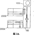
图3A-3E是工作台、分析仪和离心机的不同布置的平面图;3A-3E are plan views of different arrangements of benches, analyzers and centrifuges;

图3F是本发明的工作台和离心机与一个传送机系统一起使用的平面图;Figure 3F is a plan view of the table and centrifuge of the present invention in use with a conveyor system;

图3G是本发明的分析仪与一个传送机系统一起使用的平面图;Figure 3G is a plan view of the analyzer of the present invention in use with a conveyor system;

图4是图1的工作台的平面图;Fig. 4 is the plan view of the workbench of Fig. 1;

图5与图4类似,是图1的工作台的示意图,显示了用于固定夹持器的定位销的位置和用于探测夹持器的探测器的位置;Fig. 5 is similar to Fig. 4, is the schematic diagram of the workbench of Fig. 1, has shown the position of the positioning pin that is used to fix the gripper and the position of the detector that is used to detect gripper;

图6A-6C显示了用在图5的工作台上的定位销的不同形式;Figures 6A-6C show different forms of alignment pins used on the table of Figure 5;

图7是图5的工作台的局部剖视图,显示了一个用于探测存在一个夹持器的探测器;Figure 7 is a partial cross-sectional view of the table of Figure 5, showing a detector for detecting the presence of a gripper;

图8A是用于本系统的一个扇形体的立体图,并显示了工作台的定位销如何与扇形体连接;Figure 8A is a perspective view of a segment used in the present system and shows how the positioning pins of the workbench are connected to the segment;

图8B和8C是图8A的扇形体的俯视图和仰视图;8B and 8C are top and bottom views of the sector of FIG. 8A;

图8D是显示图8A的扇形体的另一结构的局部立体图;Fig. 8D is a partial perspective view showing another structure of the fan-shaped body in Fig. 8A;

图9A和9B分别是用于本发明的系统的一个支架的俯视图和侧视图;9A and 9B are top and side views, respectively, of a stand for use in the system of the present invention;

图9C和9D是图9A和9B的支架的插入部分的分解图和局部侧剖视图;9C and 9D are exploded and partial side cross-sectional views of the insertion portion of the stent of FIGS. 9A and 9B;

图10A是一个位于本发明系统的离心机主轴箱托板中的接受槽的俯视图;Figure 10A is a top view of a receiving slot in the centrifuge headstock support of the system of the present invention;

图10B是图10A中的接受槽的侧视图;Figure 10B is a side view of the receiving tank in Figure 10A;

图10C是图10A中的接受槽的仰视立体图,显示了离心机托板的另一种结构;Figure 10C is a bottom perspective view of the receiving tank in Figure 10A, showing another structure of the centrifuge pallet;

图11A-11D显示了对于根据本发明的离心机接受槽的不同装载方式;Figures 11A-11D show different loading modes for centrifuge receiving tanks according to the present invention;

图12A是图1的工作台的运送位置调节装置的俯视图;Fig. 12A is a top view of the transport position adjusting device of the workbench of Fig. 1;

图12B是沿着图12A中的线12B-12B截取的调节装置的剖面图;Figure 12B is a cross-sectional view of the adjustment device taken along line 12B-12B in Figure 12A;

图13A-13D是图1的工作台的自动臂的细节,图13A是一个立体图;图13B是显示自动臂相对于图1的工作台的一个运动范围的平面图;图13C是自动臂的一个抓手装置头部和一个光学头部传感器的局部分解立体图;图13D是与图13C相同的立体图,显示了光学传感器的另一结构;13A-13D are details of the automatic arm of the workbench of FIG. 1, and FIG. 13A is a perspective view; FIG. 13B is a plan view showing a range of motion of the automatic arm relative to the workbench of FIG. 1; FIG. Partially exploded perspective view of the hand device head and an optical head sensor; FIG. 13D is the same perspective view as FIG. 13C, showing another structure of the optical sensor;

图14A和14B是图1的系统的一个分析仪的主视图和侧视图,图14B是沿着图14A中的线14B-14B截取的;14A and 14B are front and side views of an analyzer of the system of FIG. 1 , with FIG. 14B taken along line 14B-14B in FIG. 14A;

图15A-15G显示了图14A的分析仪自动臂的一个抓手装置部分的细节,15A和15B是主视图和右侧视图;图15C是与图15B的右侧视图,图中抓手装置部分下降与一个扇形体配合;图15D和15E是沿着图15A的线15D-15D的截面图;图15E显示了与一个扇形体的配合;以及图15G是显示抓手装置部分另一结构的一个立体图;Figures 15A-15G show details of a part of the gripper mechanism of the automatic arm of the analyzer of Figure 14A, 15A and 15B are front and right side views; Figure 15C is a right side view of Figure 15B, with part of the gripper mechanism Descend to cooperate with a sector; Figure 15D and 15E are cross-sectional views along the line 15D-15D of Figure 15A; Figure 15E shows the cooperation with a sector; and Figure 15G is a one showing another structure of the grip device part stereogram;

图16A是图1的系统的一个离心机的局部前视立体图;16A is a partial front perspective view of a centrifuge of the system of FIG. 1;

图16B是一个局部细节后视立体图,显示了图16A的离心机装置的一个入口小门的另一结构;Figure 16B is a partial detailed rear perspective view showing another configuration of an inlet wicket of the centrifuge unit of Figure 16A;

图16C是一个细节立体图,显示了图16B的入口小门的一个驱动装置;Figure 16C is a detailed perspective view showing an actuation mechanism for the entrance wicket of Figure 16B;

图16D和16E是图16B的离心机装置的一个图示方框图和一个电路方框图;Figures 16D and 16E are a schematic block diagram and an electrical block diagram of the centrifuge device of Figure 16B;

图16F是图16B的离心机装置的一个电路接口组件的放大电路图;Figure 16F is an enlarged circuit diagram of a circuit interface assembly of the centrifuge device of Figure 16B;

图16G是图16B的离心机装置的一个计算机程序的流程图;Figure 16G is a flowchart of a computer program for the centrifuge device of Figure 16B;

图17A和17B分别是图1的系统的平衡子系统的一个俯视图和一个侧视图;17A and 17B are a top view and a side view, respectively, of the balancing subsystem of the system of FIG. 1;

图18A是图1的系统的去顶盖子系统的立体图;18A is a perspective view of the decapping subsystem of the system of FIG. 1;

图18B是显示工作台上的图18A的去顶盖子系统的平面图;18B is a plan view showing the decapping subsystem of FIG. 18A on a bench;

图18C是显示图18A的去顶盖系统的一部分的另一结构的立体图;18C is a perspective view showing another configuration of a portion of the decapping system of FIG. 18A;

图18D和18E是图18C的去顶盖系统部分的侧剖面图和仰视图;18D and 18E are side sectional and bottom views of portions of the decapping system of FIG. 18C;

图18F是图18A的去顶盖系统部分的另一接受器部分的局部侧视图;18F is a partial side view of another receptacle portion of the decapping system portion of FIG. 18A;

图19是图1的系统的一个气动子系统的示意图;Figure 19 is a schematic diagram of a pneumatic subsystem of the system of Figure 1;

图20A和20B是图1的系统的一个工作台平台的分解立体图和侧视图;20A and 20B are exploded perspective views and side views of a workbench platform of the system of FIG. 1;

图21是工作台的一个防护罩的一个门部分的局部截面图;描述Figure 21 is a partial sectional view of a door portion of a protective cover of the workbench; description

系统综述systematic review

参看图1、2、4、8A、9A和10A,根据本发明的一个系统10包括:一个工作台100、一个离心机装置1000和至少一个分析仪2000,一般是标明为2000A和2000B的两个分析仪,这些作为本系统的主要组成部分。由一个操作者在工作台100装上容器12,例如试管102(参看图8)。试管102上带有识别标记,即一个条形码104和一个顶盖103。容器一般放在一个夹持器14,例如一个扇形体300(图8A)或一个试管支架600(图9A)中。为了进行离心处理,容器12一般被转移到接受器或接受槽1200(图10A)。Referring to Figures 1, 2, 4, 8A, 9A and 10A, a system 10 according to the present invention includes a bench 100, a centrifuge unit 1000 and at least one analyzer 2000, generally two denoted 2000A and 2000B. analyzers, these serve as the main components of this system. The station 100 is loaded with containers 12, such as test tubes 102, by an operator (see FIG. 8). The test tube 102 has identification marks, ie a barcode 104 and a cap 103 . The containers are typically placed in a holder 14, such as a quadrant 300 (FIG. 8A) or a test tube holder 600 (FIG. 9A). For centrifugation, container 12 is typically transferred to a receiver or tank 1200 (FIG. 10A).

如图2A所示,系统10的一个处理监控装置200包括一个探测输入步骤202,用于探测在工作台100的输入位置16(图4)的容器12的存在。在一个容器选择步骤204中,被探测的容器12被选择进行处理。除了需要优先或“STAT”处理的容器外,处理是以先进先出为基础。那些容器12由操作者放入工作台100上的一个优先区18内以便优先处理。As shown in FIG. 2A, a process monitoring device 200 of system 10 includes a detect input step 202 for detecting the presence of container 12 at input location 16 of station 100 (FIG. 4). In a container selection step 204, detected containers 12 are selected for processing. Processing is on a first-in-first-out basis, except for containers that require priority or "STAT" processing. Those containers 12 are placed by the operator into a priority area 18 on the station 100 for priority processing.

在选择了用于处理的一个容器12后,在容器识别标记读取步骤206读取容器识别标记,即条形码104,并且在处理选择步骤208基于对容器12的具体处理确定主要处理分项。该容器然后在离心步骤210、去掉顶盖步骤212、分析步骤214和输出分类步骤216的一个或多个中进行处理。After a container 12 is selected for processing, the container identification mark, ie, the barcode 104 is read at a container identification mark reading step 206 and the main processing sub-items are determined at a process selection step 208 based on the specific processing of the container 12 . The container is then processed in one or more of a centrifugation step 210 , a decapping step 212 , an analysis step 214 , and an output sorting step 216 .

对于要经过整个处理过程的试样,容器由离心步骤210送到离心子系统以便在离心机装置1000(图16A-16G)中进行离心处理。被离心处理的容器随后在去掉顶盖步骤212中由一个去掉顶盖子系统900处理(图18A-18B)。接着,去掉顶盖的试样被输送到分析步骤214以便在任何可获得的分析仪上进行分析。大体上,可以进行对生物料样有效的任何类型的分析,包括尿、血液和脑脊髓液的分析。而且,本发明的系统10能用于工业分析,因此它不局限于生物物质。For samples to be processed throughout, the container is sent from the centrifugation step 210 to the centrifugation subsystem for centrifugation in the centrifuge assembly 1000 (FIGS. 16A-16G). The centrifuged containers are then processed by a decapping subsystem 900 in a decapping step 212 (FIGS. 18A-18B). Next, the decapped sample is delivered to analysis step 214 for analysis on any available analyzer. In general, any type of analysis valid for biological samples, including analysis of urine, blood and cerebrospinal fluid, can be performed. Furthermore, the system 10 of the present invention can be used for industrial analysis, so it is not limited to biological substances.

在一个或两个分析仪2000上分析之后,容器被送回到工作台100,并随后在输出分类步骤216中取出分类,其中,每个容器12被放入一个特定的夹持器14中。一些夹持器14用于还要进行进一步分析或处理的容器,其它的夹持器用于已完成处理的容器。After analysis on one or two analyzers 2000 , the containers are returned to the station 100 and subsequently sorted in an output sorting step 216 , in which each container 12 is placed in a specific holder 14 . Some holders 14 are for containers that are yet to be further analyzed or processed, other holders are for containers that have already been processed.

如图2A所示,容器12不必经过全部处理步骤210、2122、214和216。例如,工作台100能仅用于取出分类。另外,它能用于不需要分离和/或去掉顶盖的容器,监控装置200采用处理选择步骤208的结果以便确定后续的处理步骤。例如,合适的容器12可直接送去分析并随后取出分类。As shown in FIG. 2A , container 12 need not go through all of processing steps 210 , 2122 , 214 and 216 . For example, the workstation 100 can be used only for take-out sorting. In addition, it can be used for containers that do not require separation and/or decapping, and the monitoring device 200 uses the results of the processing selection step 208 to determine subsequent processing steps. For example, suitable containers 12 may be sent directly for analysis and subsequently removed for sorting.

以下将详细描述的离心机装置1000设计用于将装在接受器或接受槽1200(图10A)中的容器进行离心处理。每个接受槽1200装有多个将被离心处理的容器,并且离心机1000用于使多个接受槽进行离心处理,一般是四个。离心机的合适运行和避免离心机的损坏是很重要的,装在离心机中的接受槽有大体相同的重量,偏差一般是在大约10克以内。The centrifuge apparatus 1000, described in detail below, is designed to centrifuge containers contained in a receptacle or tank 1200 (FIG. 10A). Each receiving tank 1200 is equipped with a plurality of containers to be centrifuged, and the centrifuge 1000 is used to centrifuge a plurality of receiving tanks, generally four. It is important for the proper operation of the centrifuge and to avoid damage to the centrifuge. The receiving tanks installed in the centrifuge have approximately the same weight, and the deviation is generally within about 10 grams.

离心步骤210监控大体上如图2B所示的离心子系统。在离心子系统中,接受槽1200装入选定的位置,每个接受槽中的各个容器的位置存储在存储器中。接受槽以预定的顺序装入以便被近似平衡以及被需要离心处理的容器12的具体的补充物合理地许可。优选地,由一个平衡系统800(图17A,17B)监控装入过程,并且可进一步平衡接受槽1200以符合预定的公差。被平衡的接受槽随后装入离心机1000、进行离心处理并被取出。然后,再将单个的容器12从接受槽1200中取出以便进一步的处理。The centrifugation step 210 monitors the centrifugation subsystem generally as shown in Figure 2B. In the centrifuge subsystem, the receivers 1200 are loaded into selected locations, and the positions of the individual containers in each receiver are stored in memory. The receiving tanks are loaded in a predetermined order so as to be approximately balanced and reasonably permitted by the specific replenishment of containers 12 requiring centrifugation. Preferably, the loading process is monitored by a balancing system 800 (FIGS. 17A, 17B), and the receiving tank 1200 can be further balanced to meet predetermined tolerances. The equilibrated receiver tanks are then loaded into centrifuge 1000, centrifuged and removed. The individual containers 12 are then removed from the receiving tank 1200 for further processing.

分析步骤214监控大体上如图2C所示的分析子系统,容器12(一般是试管102)被放入扇形体300,与容器放入其中的特定扇形体对应的数据被存储在一个处理控制器500的存储器中。如图1所示,一个装有试管的扇形体300通过工作台100的一个自动臂110放在工作台100的一个运送位置106,每个分析仪都有一个运送位置106。一个分析仪自动臂2002将扇形体从运送位置106捡起并运送到一个分析仪转移位置2004。接着,分析仪2000按照来自处理控制器的处理指令分析试样,并将分析结果存储在处理控制器500的存储器中。然后,分析仪自动臂2002将装有分析过的试样的扇形体300从分析仪转移位置2004捡起并将它们送到工作台接受位置110。在工作台接受位置110的扇形体300随后由工作台自动臂700捡起以便分类。Analysis step 214 monitors the analysis subsystem generally as shown in FIG. 2C, containers 12 (typically test tubes 102) are placed into sectors 300, and data corresponding to the particular sector into which the containers are placed is stored in a process controller 500 in memory. As shown in FIG. 1, a quadrant 300 containing test tubes is placed by a robotic arm 110 of the worktable 100 at a delivery location 106 of the worktable 100, one delivery location 106 for each analyzer. An analyzer robotic arm 2002 picks up and transports the sectors from the delivery location 106 to an analyzer transfer location 2004 . Next, the analyzer 2000 analyzes the sample according to the processing instruction from the processing controller, and stores the analysis result in the memory of the processing controller 500 . Then, the analyzer robotic arm 2002 picks up the sectors 300 containing the analyzed samples from the analyzer transfer position 2004 and sends them to the bench receiving position 110 . The sectors 300 at the table receiving position 110 are then picked up by the table robot arm 700 for sorting.

图2D显示了数据和运行指令信息在系统10的不同部分之间的流程图。该系统包括中心处理控制器500,它一般是一个计算机系统。例如,可以使用的计算机系统是广泛可得的32位个人计算机的工业类似物,该计算机具有在几兆位范围内的读写存储器。控制器500装有一个合适的输入装置,例如,一个键盘、触摸屏、卡片读取器或另一计算机,用于将处理指令输入存储器以便根据容器识别标记处理每个容器12。FIG. 2D shows the flow of data and operational order information between different parts of the system 10 . The system includes a central processing controller 500, which is typically a computer system. For example, computer systems that may be used are industrial analogues of widely available 32-bit personal computers with read-write memory in the range of several megabits. Controller 500 incorporates a suitable input device, such as a keyboard, touch screen, card reader or another computer, for entering processing instructions into memory for processing each container 12 according to the container identification indicia.

处理控制器500利用以工作台状态和样品识别数据形式的反馈提供用于机械控制工作台100的指令。每个分析仪2000分别装有各自的控制器2008A和2008B以及用于自动臂2002的分开的控制器2010A和2010B。分析仪控制器2008A和2008B可以是商业上可买到的工业微型计算机或处理控制器500的类似物。每个分析仪控制器2008A和2008B有一个输出连接装置,用于向中心控制器500提供来自每个分析仪的关于可利用性的信息,即分析仪是否能进行一个具体的化验以及化验结果。回过来,处理控制器500对每个试样向每个分析仪2000提出化验要求以及通过对应的控制器2008A和2008B的一个输入连接装置提供运行指令。类似地,处理控制器500向每个分析仪自动臂控制器2010A和2010B提供不同的装载和卸载指令。用于分析仪自动臂控制器2010A和2010B的合适装置可以从许多工业机器人供应商获得。The process controller 500 uses feedback in the form of stage status and sample identification data to provide instructions for mechanically controlling the stage 100 . Each analyzer 2000 is equipped with a respective controller 2008A and 2008B and a separate controller 2010A and 2010B for the robotic arm 2002, respectively. Analyzer controllers 2008A and 2008B may be commercially available industrial microcomputers or the like of process controller 500 . Each analyzer controller 2008A and 2008B has an output connection for providing information to the central controller 500 from each analyzer regarding the availability, ie whether the analyzer is capable of performing a particular assay and the assay results. In turn, the process controller 500 requests assays for each sample to each analyzer 2000 and provides run instructions through an input connection of the corresponding controllers 2008A and 2008B. Similarly, process controller 500 provides different loading and unloading instructions to each analyzer robot controller 2010A and 2010B. Suitable devices for analyzer robotic arm controllers 2010A and 2010B are available from a number of industrial robot suppliers.

根据每个分析仪输出向中心控制器500提供的分析仪获得的信息,中心控制器选择确定哪个分析仪用于各个试样。这可以通过装在控制器存储器中的软件来完成,在存储器中,软件将分析仪可获得的信息与试样所需进行的化验进行对比。分析仪可获得信息包括每个分析仪能进行什么化验以及分析仪的状态信息,例如,是否已经装入了用于特定化验的试剂以及分析仪是否有储备可用。Based on the analyzer-acquired information each analyzer output provides to the central controller 500, the central controller selects which analyzer to use for each sample. This can be accomplished by software contained in the memory of the controller, where the software compares the information available to the analyzer with the assays required to be performed on the sample. Information available to the analyzers includes what assays each analyzer can perform as well as analyzer status information such as whether reagents for a particular assay have been loaded and whether the analyzer has reserves available.

处理控制器500也向离心机装置1000提供机械控制指令并从离心机装置接受状态信息。The process controller 500 also provides mechanical control commands to the centrifuge device 1000 and receives status information from the centrifuge device.

有选择地,整个系统可与一个主计算机502连接。主计算机502可与多个系统连接,每个系统包括一个工作台、一个离心机和一个或多个分析仪。主计算机可用于对每个试样向处理控制器500输入指令,并且化验结果可由中心处理控制器500报告给主计算机502。Optionally, the entire system can be connected to a host computer 502 . Host computer 502 can interface with multiple systems, each system including a bench, a centrifuge, and one or more analyzers. A host computer can be used to input instructions to the processing controller 500 for each sample, and assay results can be reported by the central processing controller 500 to the host computer 502 .

在系统的组成部分,即输出单元、输出系统单元和输入系统之间的连接装置可以是现有的数据连接件,例如,与电缆、总母线、和诸如IR传输或直接硬导线的数据传输装置相互连接的RS232连接器。系统部件布置The connection means between the system components, i.e. the output unit, the output system unit and the input system can be existing data connections, for example, with cables, bus bars, and data transmission means such as IR transmission or direct hard wires Interconnected RS232 connectors. System Component Arrangement

如图1所示,工作台100包括一个具有一个平台顶面114的平台112。工作台有一个前部或输入部116、一个后部或分析仪部118和两个相对的侧部120。前部具有放置夹持器14的放置位置,夹持器14用于存放将要处理的容器12、已经完成了处理的容器和已被部分地处理了的容器。沿着平台的中部是一个供自动臂700使用的导轨704。As shown in FIG. 1 , workbench 100 includes a platform 112 having a platform top surface 114 . The bench has a front or input section 116 , a rear or analyzer section 118 and two opposing sides 120 . The front part has a place for holding holders 14 for storing containers 12 to be processed, containers which have already been processed and containers which have been partially processed. Along the middle of the platform is a rail 704 for the robotic arm 700 .

该系统适于与多种结构的夹持器14一起使用。例如,它能用于如图8A、8B和8C所示的扇形体300,该扇形体可存放少量的试管102。扇形体300尤其适用于需要经过同样处理的容器。如下详述,自动臂700具有抓手装置726,抓手装置726不仅用于抓起单个的容器12而且还抓起扇形体300,结果,能运输一组容器12以便同时进行各种处理步骤。工作台100也能与支架600一起使用,如图9所示,该支架能存放多个容器。一般是试管102的容器12一个接一个地从支架600中取出用于处理。优选地,支架600放得比扇形体300更接近自动臂导轨704,以有助于提高和增大系统的处理能力。在工作台100的分析仪部118,有装有容器的扇形体300,用于向分析仪2000输送或接受来自分析仪2000的容器。The system is suitable for use with various configurations of holders 14 . For example, it can be used with a quadrant 300 as shown in Figures 8A, 8B and 8C, which can store a small number of test tubes 102. The sector 300 is especially suitable for containers that need to be treated as such. As detailed below, the robotic arm 700 has a gripping device 726 for gripping not only individual containers 12 but also segments 300, and as a result, a group of containers 12 can be transported for various processing steps simultaneously. The workstation 100 can also be used with a stand 600, as shown in FIG. 9, which can store multiple containers. Containers 12, typically test tubes 102, are removed one by one from rack 600 for processing. Preferably, the bracket 600 is placed closer to the robotic arm rail 704 than the sector 300 to help improve and increase the processing capacity of the system. In the analyzer section 118 of the workbench 100 , there is a quadrant 300 containing containers for delivering or receiving containers to or from the analyzer 2000 .

如图1所示,工作台自动臂700优选地居中地位于平台112上,以便容易接近平台的前输入部116和分析仪部118。而且,离心机1000优选地安装在工作台100的一个侧部120处,以便操作者能接近平台112的前部或输入部116的全部长度,后部或分析仪部118保留供分析仪2000进入。As shown in FIG. 1 , the bench robot arm 700 is preferably centrally located on the platform 112 for easy access to the front input section 116 and analyzer section 118 of the platform. Also, the centrifuge 1000 is preferably mounted at one side 120 of the bench 100 so that the operator has access to the full length of the front or input section 116 of the platform 112, with the rear or analyzer section 118 reserved for access by the analyzer 2000 .

在图1的布置中,分析仪2000以使它们的侧部接近、优选地是毗连工作台100的方式安装,并使两个分析仪2000背靠背。在图1的结构中,工作台100不会妨碍任何一个分析仪的运行,并且任何一个分析仪也不会妨碍工作台的运行。此外,位于工作台一个端部的离心机1000也不妨碍分析仪和工作台。分析仪大体上是相同的,区别在于一个分析仪(2000A)“在右边装备”它的自动臂2002A,以到达工作台100的右边,第二个分析仪2000B“在左边装备”它的自动臂2002B,以到达工作台100的左边。In the arrangement of FIG. 1 , the analyzers 2000 are mounted with their sides close to, preferably adjoining, the bench 100 , with the two analyzers 2000 back to back. In the configuration of FIG. 1, the workbench 100 does not interfere with the operation of any analyzer, and neither analyzer interferes with the operation of the workbench. In addition, the centrifuge 1000 located at one end of the bench does not interfere with the analyzer and bench. The analyzers are substantially the same, with the difference that one analyzer (2000A) is "armed on the right" with its robotic arm 2002A to reach the right of the table 100, and the second analyzer 2000B is "armed on the left" with its robotic arm 2002B to reach the left of workbench 100 .

图3A是图1所示系统的布置的俯视图。另外可能的布置如图3B-3F所示。图3B的布置与图3A的布置相同,除了离心机1000放在由工作台100和两个分析仪2000形成的一个U形空间中并紧靠两个分析仪的底部2012的后部2020。FIG. 3A is a top view of the arrangement of the system shown in FIG. 1 . Another possible arrangement is shown in Figures 3B-3F. The arrangement of FIG. 3B is the same as that of FIG. 3A except that the centrifuge 1000 is placed in a U-shaped space formed by the table 100 and the two analyzers 2000 and abuts the rear 2020 of the bottom 2012 of the two analyzers.

在图3C所示的本发明的形式中,布置与图3B所示的布置相同,除了第二分析仪2000B紧靠着工作台100远离第一分析仪的那一端放置。In the form of the invention shown in Figure 3C, the arrangement is the same as that shown in Figure 3B, except that the second analyzer 2000B is placed next to the end of the table 100 remote from the first analyzer.

在图3D的布置中,两个分析仪2000放置在工作台100的相对侧,从而形成一个“十”字形,右侧分析仪2000A紧靠工作台的后部118,左侧分析仪2000B紧靠工作台100的前部116。离心机1000如图3A的布置一样位于工作台的一个端部。In the arrangement of Figure 3D, the two analyzers 2000 are placed on opposite sides of the bench 100 so as to form a "cross" shape, with the right analyzer 2000A abutting the rear 118 of the bench and the left analyzer 2000B abutting Front 116 of work bench 100 . The centrifuge 1000 is located at one end of the bench as in the arrangement of Figure 3A.

图3E的布置类似于图3D的布置,除了两个分析仪2000安放在工作台100的离心机端而不是在工作台的中部。图3E的布置与图3D的布置相比的优点在于,工作台的输入侧不被任何分析仪所妨碍。The arrangement of Figure 3E is similar to that of Figure 3D, except that the two analyzers 2000 are placed at the centrifuge end of the bench 100 rather than in the middle of the bench. The arrangement of Figure 3E has the advantage over that of Figure 3D that the input side of the bench is not obstructed by any analyzers.

从这些不同的布置可以看出,可以安装工作台和离心机1000以使它们不妨碍接近任何一个分析仪。As can be seen from these various arrangements, the bench and centrifuge 1000 can be installed so that they do not obstruct access to either analyzer.

本发明的工作台和离心机不局限于如图3A-3E所示的直接连同分析仪一起使用。而且,它们能与包括一个传送机126的传送机系统一起使用,如图3F和3E所示。在图3E的形式中,工作台的自动臂700从传送机126上拾起一般位于扇形体中的容器,对容器进行处理,并有选择地对容器进行离心处理。随后,处理过的容器被送回到传送机126。The bench and centrifuge of the present invention are not limited to use directly with the analyzer as shown in Figures 3A-3E. Also, they can be used with conveyor systems that include a conveyor 126, as shown in Figures 3F and 3E. In the version of FIG. 3E, the robotic arm 700 of the station picks up the containers generally in the quadrant from the conveyor 126, processes the containers, and optionally centrifuges the containers. The processed containers are then returned to the conveyor 126 .

在图3G的形式中,传送机与分析仪2000配合,分析仪的自动臂2002将容器和/或扇形体拾起并送到传送机126。分析仪In the version of FIG. 3G , the conveyor cooperates with the analyzer 2000 , whose robotic arm 2002 picks up and delivers the containers and/or segments to the conveyor 126 . Analyzer

图1中所示的分析仪2000是由Califomia Fullerton的Beckman仪器公司提供的Synchron CX分析仪装置,可以将它进行修改或改型以便装有这里所述的自动臂2002。如图14A和14B所示,每个分析仪2000有一个基座2012,基座具有相对的侧部2014、一个前部2016、一个顶部2018和一个后部2020。顶部2018具有分析仪移动位置2004和在其上的分析装置,使用者可以从前部接近顶部2018。支架2022安装在基座2012的顶部2018的后部,支架2022具有一个前工作区2024和一个顶板2026。在顶板2026上是一个包括自动臂2002的传递机构,用于将试样从工作台100自动传递到分析仪2000,以及用于将分析后的试样从分析仪2000传递到工作台100。具有驱动装置2030的一个轨道或导轨2028延伸贯穿顶板2026,用于沿着导轨2028移动自动臂2002。自动臂2002具有一个导轨啮合部件2032和一个延伸臂2034,延伸臂2034从导轨啮合部件2032沿着轨道2028延伸的相同方向延伸。从延伸臂2034的端部,有一个向前延伸臂2036,在向前延伸臂2036的端部有一个向下悬臂2038。在向前延伸臂的底端是抓手装置2040。The analyzer 2000 shown in FIG. 1 is a Synchron CX analyzer unit supplied by Beckman Instruments Company of Fullerton, California, which may be modified or retrofitted to incorporate the robotic arm 2002 described herein. As shown in FIGS. 14A and 14B , each analyzer 2000 has a base 2012 with opposing sides 2014 , a front 2016 , a top 2018 and a rear 2020 . The top 2018 has an analyzer mobile station 2004 and the analysis device thereon, and the top 2018 is accessible from the front by the user. Mounted on the rear of the top 2018 of the base 2012 is a stand 2022 having a front working area 2024 and a top plate 2026 . On top plate 2026 is a transfer mechanism including robotic arm 2002 for automatically transferring samples from workbench 100 to analyzer 2000 and for transferring analyzed samples from analyzer 2000 to workbench 100 . A track or rail 2028 with drive means 2030 extends through the top plate 2026 for moving the robotic arm 2002 along the rail 2028 . Robotic arm 2002 has a rail engaging member 2032 and an extension arm 2034 that extends from rail engaging member 2032 in the same direction that rail 2028 extends. From the end of the extending arm 2034, there is a forward extending arm 2036 and at the end of the forward extending arm 2036 there is a downwardly cantilevered arm 2038. At the bottom end of the forwardly extending arm is a gripping device 2040 .

由于有延伸臂2034,抓手装置2040能到达工作台100上的扇形体300。而且,在“静止”状态,第一分析仪2000A的自动臂2002A不会妨碍基座2012的顶部2018和支架的前工作区,从而不会妨碍处理和操作者接近分析仪。Thanks to the extension arm 2034 , the gripper device 2040 can reach the sector 300 on the table 100 . Also, in the "rest" state, the robotic arm 2002A of the first analyzer 2000A does not obstruct the top 2018 of the base 2012 and the front working area of the stand, thereby preventing handling and operator access to the analyzer.

进一步如图15A-15F所示,每个分析仪自动臂2002的抓手装置2040由一个抓手装置传动装置2041支承,传动装置2041安装在一个托架2042上,托架刚性地固定在自动臂2002的升降部件2043上。一个曲柄部件2044可绕着传动装置2041的竖直轴线2045在第一和第二位置之间经过大约180度的角度移动,以便选择相反取向地将扇形体300放置在分析仪转移位置2004和工作台运送位置106上或回收其上的扇形体。一个自动钳2046安装到曲柄部件2044的一个端部末端,用于可移动地支承一对朝向外部的钩形抓手装置部件2048,每个抓手装置部件2048可插入扇形体300的各个顶部壁槽322中,以下将结合图8A-8C对扇形体300进行描述。这样插入以后,一旦自动钳2046启动以使抓手装置部件2048分开,抓手装置部件2048的钩形端部末端2049嵌入顶部壁306(在其上形成有槽322)的下侧。而且,每个抓手装置部件2048有一个与其竖直可滑动地配合的提取器部件2050,一个竖直定向的压缩弹簧2052安放在提取器部件的上方,用于在抓手装置部件伸入槽322时在槽322之间偏压地接触顶部壁306。提取器部件2050的一个目的是确保在扇形体300被放置在一个位置时扇形体保持一个不受干扰的状态,在升降部件2043提升、撤回抓手装置部件2048的过程中,提取器保持扇形体300向下。提取器部件2050的另一个目的是在分析仪抓手装置2040的操作过程中使抓手装置部件2048上的扇形体300稳定。As further shown in Figures 15A-15F, the gripper device 2040 of each analyzer automatic arm 2002 is supported by a gripper device transmission 2041, and the transmission device 2041 is mounted on a bracket 2042, which is rigidly fixed to the automatic arm. 2002 on the lifting part 2043. A crank member 2044 is movable about the vertical axis 2045 of the transmission 2041 through an angular movement of approximately 180 degrees between first and second positions to select opposite orientations for placing the segments 300 in the analyzer transfer position 2004 and operating The table transports the segments on or retrieves the position 106. An automatic pincer 2046 is mounted to one end end of the crank member 2044 for movably supporting a pair of outwardly facing hook-shaped gripper members 2048 each insertable into a respective top wall of the sector 300 In the slot 322, the sector 300 will be described below with reference to FIGS. 8A-8C. After such insertion, the hooked end 2049 of the gripper member 2048 engages the underside of the top wall 306 (in which the slot 322 is formed) once the automatic pliers 2046 are activated to separate the gripper members 2048 . Moreover, each gripper member 2048 has an extractor member 2050 vertically and slidably engaged therewith, and a vertically oriented compression spring 2052 is positioned above the extractor member for use when the gripper member extends into the slot. The top wall 306 is biasedly contacted between the slots 322 at 322 . One purpose of the extractor part 2050 is to ensure that the sector 300 remains in an undisturbed state when the sector 300 is placed in a position, and that the extractor holds the sector during lifting and retraction of the gripper part 2048 by the lifting part 2043 300 down. Another purpose of the extractor member 2050 is to stabilize the segments 300 on the gripper member 2048 during operation of the analyzer gripper 2040 .

一个适于传动装置2041的装置可以是加拿大Tustin的SMC公司供应的型号为NCRB/BW30-180S旋转传动装置。一个适于用作自动钳2046的装置可以是纽约Hauppauge的Festo公司供应的HGP-10-A型抓手装置。适于用作分析仪导轨2028和驱动装置2030的装置可以是加拿大Torrance的Intelligent Actuator公司供应的带有型号为SA-A竖直移动部件的型号为IS-MX-20-200-400自动定位系统。One suitable device for transmission 2041 may be the model NCRB/BW30-180S rotary transmission available from SMC Corporation of Tustin, Canada. One device suitable for use as automatic pliers 2046 may be the model HGP-10-A gripper device available from Festo Corporation of Hauppauge, New York. A device suitable for use as the analyzer guide rail 2028 and drive unit 2030 may be the IS-MX-20-200-400 Automatic Positioning System with the SA-A vertical moving part supplied by Intelligent Actuator Corporation of Torrance, Canada .

进一步参考图15G,可用于扇形体300’的抓手装置部件2048优选的另一结构包括一个抓手装置部件,标号为2048’,用于嵌入弹性快334,以及一个辅助抓手装置部件,标号为2048”,用于夹紧扇形体300’的后壁305。工作台With further reference to FIG. 15G, another preferred structure of the gripping device part 2048 that can be used in the sector 300' includes a gripping device part, reference numeral 2048', for embedding the elastic fast 334, and an auxiliary gripping device part, reference number 2048", used to clamp the rear wall 305 of the quadrant 300'. Workbench

一个优选的工作台100或实验台的布置如图4所示。这种布置尤其适合在工作台100的右侧具有离心机1000,如图1和4所示。在平台112的输入部分116上,具有从左到右标为A-O的供扇形体300使用的十五个分类位置128、以及供安放试管的支架使用的对应的十五个分类位置130A-O。供自动臂700使用的导轨沿着平台的中部延伸,从一端延伸到另一端,将平台分成输入部分116和分析仪部分118。支架比扇形体更接近导轨704,因为对于支架自动臂需要更多次的输送,支架上的容器需要一个接一个地装和卸。A preferred workbench 100 or lab bench arrangement is shown in FIG. 4 . This arrangement is particularly suitable for having the centrifuge 1000 on the right side of the bench 100 as shown in FIGS. 1 and 4 . On the input portion 116 of the platform 112, there are fifteen sorting positions 128, labeled A-O from left to right, for the sectors 300, and corresponding fifteen sorting positions 130A-O for the racks holding the test tubes. Rails for the robotic arm 700 run along the middle of the platform, from one end to the other, dividing the platform into an input section 116 and an analyzer section 118 . The racks are closer to the rails 704 than the sectors because more transfers are required for the rack robotic arm, and the containers on the racks need to be loaded and unloaded one by one.

在扇形体和支架位置的一般分配中,输入位置16包括标为A-J的支架位置128和扇形体位置130,这里放置将要被处理的新容器(包括在位置A供“STAT”试样使用的优先区18);输出位置17包括位置N和O,这里放置已完成处理并等待从工作台100上移走的扇形体和支架;辅助区19包括位置K-M,这里放置装有准备进行分析的试样的扇形体和支架,例如,由分析仪中的一个进行第一次分析的试样,或者已由一个分析仪进行了分析并准备在第二个分析仪上进行第二次分析处理的试样。应理解的是:对于输入部分116上的位置的功能的具体划分将根据分析仪的处理速率、可供使用的分析仪数目以及其它因素而改变,在支架位置128和扇形体位置130之间的分配也可以不同。In a general assignment of quadrant and rack positions, input positions 16 include rack positions 128 labeled A-J and quadrant positions 130, where new containers to be processed (including the preferred container for "STAT" specimens at position A) are placed. area 18); the output position 17 includes positions N and O, where the quadrants and racks that have completed processing and are waiting to be removed from the workbench 100 are placed; the auxiliary area 19 includes positions K-M, where the samples containing ready-to-analyze are placed sectors and holders, e.g. samples that are analyzed for the first time by one of the analyzers, or samples that have been analyzed by one analyzer and are to be processed for a second analysis on a second analyzer . It should be understood that the specific division of functions for the positions on the input section 116 will vary depending on the processing rate of the analyzers, the number of analyzers available, and other factors. Allocations can also be different.

带有条形码识别标记601的支架600用于存放和/或分类试管,并作为从工作台上移走或放置大量试管的一种方法。尽管扇形体300具有较小的容积,但它能被自动臂700和2002拾起,不仅用于处理而且可用于对多个试管同时进行分类,从而增加了工作台100的效率。Rack 600 with barcode identification indicia 601 is used to store and/or sort test tubes and as a means of removing or placing large numbers of test tubes from the bench. Although the sector 300 has a smaller volume, it can be picked up by the robotic arms 700 and 2002 not only for handling but also for sorting multiple test tubes simultaneously, thereby increasing the efficiency of the workbench 100 .

图4所示的工作台适合与至少两个分析仪一起使用。这样,在分析仪部分118的每端的一个“发射台”105具有运送位置106,用于由分析仪自动臂2002拾起扇形体;以及接受位置110,用于从自动臂2002运送装有分析过的样品的扇形体。若干个扇形体位置134环绕在发射台周围,以便供空扇形体使用,或者当输入部分装满时在高峰处理时间放置装有试样的扇形体。The bench shown in Figure 4 is suitable for use with at least two analyzers. Thus, a "launch pad" 105 at each end of the analyzer section 118 has delivery locations 106 for picking up the sectors by the analyzer robotic arm 2002; The quadrant of the sample. A number of quadrant positions 134 surround the launch pad to accommodate empty quadrants, or to place quadrants with samples during peak processing times when the input section is full.

在分析仪侧的中部是接受器或接受槽1200、一个天平802以及平衡系统800的一个辅助支架位置804。图4显示了在天平802上有四个进行平衡的接受器或接受槽,辅助位置804具有一个供平衡试管806使用的支架,平衡试管用于平衡装有容器的接受器的重量。辅助支架位置804的右侧是去掉顶盖系统900,紧接着是四个接受器1200,它们或者是在离心处理后被取出试管,或者是装入新的试管以进行离心处理。In the middle of the analyzer side are the receiver or receiving tank 1200 , a scale 802 and an auxiliary stand location 804 for the balance system 800 . Figure 4 shows that there are four receptacles or receptacles for balancing on the balance 802, and the auxiliary position 804 has a stand for a balance tube 806 which is used to balance the weight of the receptacle containing the container. To the right of the auxiliary rack position 804 is the decap system 900, followed by four receptacles 1200 which are either removed from the tube after centrifugation or loaded into new tubes for centrifugation.

再参看图20A和20B,平台112的一个优选结构包括一个基座20,基座20具有与若干个间隔的隔板24连接的一对平行间隔的横梁部件22,隔板24各自具有支承导轨704的轨道部件26的柱形部分25。每个隔板24也在横梁部件22上装有一对柱形部件28,平台114的输入部分和分析仪部分116和118被单独地固定在各排柱形部件28的上部。由于具有这种结构,平台112可以作为一个紧凑的包装被方便地存放和运输,该紧凑包装包括横梁部件22、轨道部件26以及输入部分116和分析仪部分118,另一个紧凑包装包括具有柱形部件28固定到其上的隔板24。共有五个隔板24,在它们之间的空间限定了四个隔间用于以方便的形式安装系统10的动力分配和电气组件。在每个端部隔板24的下部装有一对旋转小脚轮130,用于可转动地支承工作台100;以及一个可调节脚组件132向内地与每个端部间隔并安装在每个横梁部件22的下部,用于以方便的形式调节和固定平台112。Referring again to FIGS. 20A and 20B , a preferred configuration of the platform 112 includes a base 20 having a pair of parallel spaced beam members 22 connected to a plurality of spaced partitions 24 each having support rails 704. The cylindrical portion 25 of the track member 26. Each bulkhead 24 also carries a pair of column members 28 on the beam member 22, and the input and analyzer sections 116 and 118 of the platform 114 are individually secured to the upper portion of each row of column members 28. Due to this structure, the platform 112 can be conveniently stored and transported as a compact package including the beam member 22, the track member 26 and the input section 116 and the analyzer section 118, and another compact package including the The bulkhead 24 to which the member 28 is secured. There are five bulkheads 24, the spaces between which define four compartments for mounting the power distribution and electrical components of the system 10 in a convenient fashion. A pair of swivel casters 130 are mounted on the lower portion of each end bulkhead 24 for rotatably supporting the workbench 100; and an adjustable foot assembly 132 is inwardly spaced from each end and mounted on each beam member 22 for adjusting and fixing the platform 112 in a convenient form.

一个通常的工作台长度为约2.83m,整个宽度为约980mm,其中输入部分宽约540mm、轨道宽约145mm以及分析部分宽约440mm。A typical table length is about 2.83m, and the overall width is about 980mm, wherein the input part is about 540mm wide, the track is about 145mm wide and the analysis part is about 440mm wide.

还是参考图1,工作台100优选地装有一个保护性的防护系统40,用于阻挡操作者进入平台顶面114上的空间。防护系统40有一个框架42,在框架42上装有若干个透明壁板部件44,壁板部件44接近平台顶面114竖直地安装,防护系统40沿着后部118间断开以便清洗各个分析仪自动臂2002A和2002B。紧邻着离心机装置100的壁板部件,标号为44A,有一个形成在其上的气泡形延伸部分46,以便将到离心机装置1000的一个通道包括在防护系统40内。另外,再参考图21,沿着前部116的壁板部件,标号为44B,从框架42的顶部向下延伸仅仅一部分,三个透明门壁板48被支承着以便相对壁板44B的各个部分重叠地竖直移动。每个门壁板48通过一个曲柄制动组件54与一个气动传动装置52的一个活塞杆50配合,传动装置52安装在框架42的顶上部。一个螺线管锁闩56与每个门壁板48相结合地安装在平台114内,以便在一个关闭位置同时锁紧门壁板。在如图21所示的示例性的结构中,当螺线管锁闩56打开时,螺线管锁闩与形成在活塞杆50下端的间断点或狭槽58配合,锁闩56启动松开杆50。门壁板48通过曲柄制动组件54依靠过量的向内力得到加强,曲柄制动组件在其上具有从动凸块60,从动凸块在壁板48的关闭位置近似地沿着平台顶面114的边缘延伸。在每个曲柄制动组件54的下面有一个门按钮62,用于向处理控制器500发出门需要打开的信号。受合适的互锁和处理悬架所支配,对应的锁闩58被驱动,接着对应的气动传动装置52被启动,于是,门壁板48被提升以便操作者接近工作台100的输入部分116。工作台100优选地装有两个备用止动装置64,分别接近输入部分116的每个端部,以供操作者使用。Still referring to FIG. 1 , the work platform 100 is preferably equipped with a protective guard system 40 for blocking the operator from entering the space on the top surface 114 of the platform. The protection system 40 has a frame 42 on which several transparent wall parts 44 are installed. The wall parts 44 are installed vertically close to the platform top surface 114. The protection system 40 is disconnected along the rear part 118 to clean each analyzer. Automatic arms 2002A and 2002B. The wall member, designated 44A, immediately adjacent to the centrifuge unit 100 has a bubble-shaped extension 46 formed therein to include a passage to the centrifuge unit 1000 within the guard system 40. In addition, referring again to FIG. 21 , along the front portion 116 of the panel member, designated 44B, extending downwardly from the top of the frame 42 for only a portion, three transparent door panels 48 are supported so as to be opposed to each portion of the panel 44B. Move vertically overlapping. Each door panel 48 cooperates via a crank brake assembly 54 with a piston rod 50 of a pneumatic actuator 52 mounted on top of the frame 42 . A solenoid latch 56 is mounted in platform 114 in conjunction with each door panel 48 for simultaneously locking the door panels in a closed position. In the exemplary configuration shown in FIG. 21, when the solenoid latch 56 is open, the solenoid latch engages a discontinuity or slot 58 formed in the lower end of the piston rod 50, and the latch 56 is activated to release. Rod 50. Door panel 48 is reinforced by means of excess inward force by crank detent assembly 54 having follower lugs 60 thereon which, in the closed position of panel 48, approximately follow the platform top surface. 114 edge extensions. Below each crank brake assembly 54 is a door button 62 for signaling to process controller 500 that the door needs to be opened. Subject to suitable interlocks and handling suspensions, the corresponding latch 58 is actuated, and the corresponding pneumatic actuator 52 is activated, whereby the door panel 48 is raised to allow operator access to the input portion 116 of the workstation 100 . The table 100 is preferably provided with two backup stops 64, one near each end of the input portion 116, for use by the operator.

参考图5,对于每个扇形体300提供两个扇形体定位柱或销142。类似地,提供两个支架定位销146用于固定工作台100上的每个支架600。一个平台磁体145与平台顶面114平齐安装并与各对销子142和146保持预定关系,以便吸住如下所述的扇形体300和支架600的各个夹持器磁体330。而且,对于用于离心机的每个接受器或接受槽1200,在工作台100上有两个接受槽定位销144。图6A-6C分别显示了一个典型的扇形体销142、支架销146和接受槽销144。选择销子的特定形状以便它们能与各自定位的装置相配合。如这些图所示,销子的三种形式不同以防操作者将装置在工作台上错误定位。还是如图6A-6C所示,平台114上的销子142、144和146位于一个浅凹部156中,以便限制从容器12的任何无意的洒落物。在天平802上也有与凹部156对应的凹部。此外,一个圆周槽158形成在平台114的前部116和后部118中并环绕着供夹持器14使用的不同位置,如图6A所示。Referring to FIG. 5 , two sector positioning posts or pins 142 are provided for each sector 300 . Similarly, two bracket positioning pins 146 are provided for fixing each bracket 600 on the workbench 100 . A platform magnet 145 is mounted flush with the platform top surface 114 and in predetermined relationship to each pair of pins 142 and 146 to attract each of the retainer magnets 330 of the segments 300 and bracket 600 as described below. Also, for each receptacle or receptacle 1200 used in the centrifuge, there are two receptacle alignment pins 144 on the table 100 . Figures 6A-6C show a typical segment pin 142, bracket pin 146 and receiving slot pin 144, respectively. The specific shape of the pins is chosen so that they will fit the respective positioning device. As shown in these figures, the three types of pins are different to prevent the operator from mispositioning the device on the workbench. As also shown in FIGS. 6A-6C , the pins 142 , 144 and 146 on the platform 114 are located in a shallow recess 156 to limit any unintentional spills from the container 12 . The balance 802 also has a recess corresponding to the recess 156 . Additionally, a circumferential groove 158 is formed in the front 116 and rear 118 of the platform 114 and surrounds the various locations for the holder 14, as shown in FIG. 6A.

扇形体销142和扇形体300之间的配合如图8A所示;支架600与支架定位销144之间的配合如图9A和9B所示;离心机接受槽1200与接受槽定位销146之间的关系如图10C所示,它显示了在离心机1000的另一种结构中的销子146。The cooperation between the sector pin 142 and the sector 300 is shown in Figure 8A; the cooperation between the bracket 600 and the bracket positioning pin 144 is shown in Figures 9A and 9B; between the centrifuge receiving groove 1200 and the receiving groove positioning pin 146 The relationship is shown in FIG. 10C , which shows the pin 146 in another configuration of the centrifuge 1000 .

工作台装有一个探测系统,用于探测工作台上存在扇形体和支架。在图7所示的本发明优选形式中,使用了置于稍低于工作台上表面凹处的一个传感器或笛簧接点管150。每个笛簧接点管150由一个平齐安装的孔塞部件152固定,孔塞部件是可以去除以便维修和/或更换笛簧接点管150。优选地,笛簧接点管150的电路带有合适的连接件(未显示)以便有助于更换笛簧接点管150而不需到达平台顶面114的下部。笛簧接点管150的位置如图5所示。可以通过提供带有磁体的扇形体、支架和接受槽来启动笛簧接点管,磁体的强度要足够强以启动笛簧接点管。此外,也可使用其它探测系统,包括重量系统,其中探测器通过重量来探测一个扇形体或类似物的存在;或者一个依靠电流的探测系统,其中一个扇形体或支架的存在接通一个电路以便测出电流;或者一个光学中断器,其中该装置断开一个光路径。The table is equipped with a detection system for detecting the presence of sectors and supports on the table. In the preferred form of the invention shown in Figure 7, a sensor or reed contact tube 150 is used which is recessed slightly below the upper surface of the table. Each reed contact tube 150 is held in place by a flush fitting plug member 152 which is removable for maintenance and/or replacement of the reed contact tube 150 . Preferably, the circuit of the reed contact tube 150 is provided with suitable connectors (not shown) to facilitate replacement of the reed contact tube 150 without accessing the lower portion of the platform top surface 114 . The position of the reed contact tube 150 is shown in FIG. 5 . The reed tube may be activated by providing the segments, bracket and receptacle with a magnet strong enough to activate the reed tube. In addition, other detection systems may be used, including gravimetric systems, where the detector uses weight to detect the presence of a segment or the like; or a current-dependent detection system, where the presence of a segment or bracket completes an electrical circuit to sense current; or an optical interrupter, where the device interrupts an optical path.

如图8A、8B和8C所示的示例性的扇形体包括一个具有一个凸形前壁302、一个凹形后壁304、一个底壁308和侧壁310的基体301。一个顶部315极容易地安装在基体301上并包括一个顶部壁306,顶部壁306从基体的侧壁310的部分向后和向外地延伸。侧壁310交错排列以便清洗工作台100的扇形体定位销142,从而形成一个突出部分318,突出部分318上有两个容纳销子142的孔320。沿着前壁302是用于容纳试管102的管形腔314,在如图所示的形式中有七个这种腔。它们从顶部壁306延伸并能通过底部壁308排出液体。每个腔的前部有一个狭槽316以便条形码读取器读取在试管102前部上的条形码104。在顶部壁306上是两个狭槽322,狭槽322由分析仪自动臂2002(图15A-15F)的抓手装置部件或夹紧装置2048嵌入。狭槽316部分地延伸在基体301中并且部分地在顶部315中。The exemplary sector shown in FIGS. 8A , 8B and 8C includes a base 301 having a convex front wall 302 , a concave rear wall 304 , a bottom wall 308 and side walls 310 . A top 315 is easily mounted on the base 301 and includes a top wall 306 extending rearwardly and outwardly from portions of the side walls 310 of the base. The side walls 310 are staggered for cleaning the sector pins 142 of the workbench 100 , thereby forming a protruding portion 318 with two holes 320 for receiving the pins 142 . Along the front wall 302 are tubular cavities 314 for receiving test tubes 102, in the form shown there are seven such cavities. They extend from the top wall 306 and are capable of draining liquid through the bottom wall 308 . The front of each chamber has a slot 316 for a barcode reader to read the barcode 104 on the front of the test tube 102 . On the top wall 306 are two slots 322 that are inserted by the gripping device components or clamping devices 2048 of the analyzer robotic arm 2002 (FIGS. 15A-15F). Slot 316 extends partly in base 301 and partly in top 315 .

从扇形体300的顶部壁306向上延伸的是一个后壁对应体,标为305,从它上面突起一个T形柄324,后壁305和柄324的组合被工作台自动臂700的抓手装置部件726(图13C)所嵌入。Extending upwardly from the top wall 306 of the sector 300 is a rear wall counterpart, designated 305, from which protrudes a T-shaped handle 324, the combination of the rear wall 305 and handle 324 being held by the gripper assembly of the table robot arm 700 Component 726 (FIG. 13C) is embedded.

扇形体300的前壁302上具有可识别的条形码326,以使中心控制器500跟踪扇形体和其中的试管。基体301也具有一个内部条形码条纹327,在试管狭槽316是空的时候,内部条形码条纹327是可见的,但试管在狭槽中时,内部条形码条纹327被遮住。这样,一个条形码扫描仪724(图13A)能给中心控制器500发出在每个扇形体中试管的数目和位置的信息。一个夹持器磁体330与底壁308平齐地安装以便在移动试管102的过程中使扇形体300稳定并使扇形体保持在工作台100原来的位置上。夹持器磁体330被定位和定向以便被工作台100的各个平台磁体145所吸引。一个传感器磁体332类似地与底壁308平齐地安装以便启动工作台100的各个笛簧接点管传感器150。The front wall 302 of the quadrant 300 has an identifiable barcode 326 to enable the central controller 500 to keep track of the quadrant and the test tubes therein. The base 301 also has an inner barcode stripe 327 that is visible when the tube slot 316 is empty but is hidden when the tube is in the slot. Thus, a bar code scanner 724 (FIG. 13A) can send information to the central controller 500 about the number and location of the test tubes in each sector. A gripper magnet 330 is mounted flush with the bottom wall 308 to stabilize the segment 300 and keep the segment in place on the table 100 during movement of the test tube 102 . Gripper magnets 330 are positioned and oriented so as to be attracted to respective platform magnets 145 of table 100 . A sensor magnet 332 is similarly mounted flush with the bottom wall 308 to activate each reed sensor 150 of the bench 100 .

参考图8D,标为300’的扇形体的另一优选结构具有后壁305(和柄324)和一个三角形弹性块334,后壁305从顶部壁306延伸并具有一个向后凸起的凸出部分305’,弹性块334接近沿着凸出部分305’的下侧固定在柄324上。与图15E的嵌入结构相比具有增大的竖直(或水平)对齐的配合公差,弹性块334有助于扇形体300被图13G所示结构中的分析仪自动臂2002的抓手装置部件2048’和2048”可靠的嵌入。通过弹性块334与一个抓手装置部件726弹性地适应以及块334与后壁305的组合具有一个非圆形的柱形,弹性块334有助于图13D的结构中的工作台自动臂700的抓手装置部件726更有效地抓取,尽管抓手装置部件的竖直定位有稍微变化,抓手装置部件的嵌入在扇形体300’和抓手装置轴线715之间形成了一个中心竖直对齐的关系。Referring to FIG. 8D, another preferred configuration of the sector designated 300' has a rear wall 305 (and handle 324) and a triangular resilient block 334, the rear wall 305 extending from the top wall 306 and having a rearwardly convex protrusion Part 305', the elastic block 334 is fixed on the handle 324 proximately along the underside of the protruding part 305'. With increased vertical (or horizontal) alignment fit tolerance compared to the embedded structure of FIG. 15E , the elastic block 334 helps the sector 300 to be held by the gripper device part of the analyzer robot arm 2002 in the structure shown in FIG. 13G 2048' and 2048 "reliably embedded. By elastically adapting the elastic block 334 to a gripper device part 726 and the combination of the block 334 and the rear wall 305 has a non-circular cylindrical shape, the elastic block 334 contributes to the The gripper part 726 of the table robot arm 700 in the structure grips more efficiently, although the vertical orientation of the gripper part varies slightly, the gripper part embedded in the sector 300' and the gripper axis 715 A central vertical alignment relationship is formed between them.

由于实验室一般处理不同来源的试样,如不同的医院、试验室和医生诊所,容器或试管102常常具有不同的直径和不同的高度。为了适应直径的变化,顶部315对于每个试管腔314有四个悬指328,悬指径向向内偏移。图8D所示扇形体300’可从Beckman Instruments withthe Synchron CX machine获得。Since laboratories typically handle samples from different sources, such as different hospitals, laboratories, and doctors' offices, the containers or tubes 102 often have different diameters and different heights. To accommodate variations in diameter, the top 315 has four fingers 328 for each cuvette lumen 314 that are offset radially inward. The sector 300' shown in Figure 8D is available from Beckman Instruments with the Synchron CX machine.

参考图9A-9D,一个适合用于系统10的试管支架600包括一个框架602,框架602具有加在其上的条形码识别标记601并限定了5×10排竖直腔603。框架包括容纳定位销146的孔604并具有夹持器磁体330和传感器磁体332的对应体。每个腔603具有带有弹簧指607的插入部606以便在支架中放置不同大小的试管,形成弹簧指以便固定一个弹性O形环部件609,O形环部件609通过弹性指607增大了作为试管102的容器12的摩擦配合。这样,每个支架600形成一个容纳容器12的夹持器14,腔603一般间隔大约20mm的间距,插入部606作成大小使得直到直径大约为16mm的容器偏置地放在中心,弹性指部件607和O形环609的组合具有足够的弹性以便使直径不大于大约13mm的容器更有效地放在中心。Referring to FIGS. 9A-9D , a test tube rack 600 suitable for use with system 10 includes a frame 602 having barcode identification indicia 601 affixed thereon and defining 5×10 rows of vertical chambers 603 . The frame includes holes 604 that receive the dowel pins 146 and have counterparts for the holder magnet 330 and the sensor magnet 332 . Each chamber 603 has an insertion portion 606 with spring fingers 607 for placing test tubes of different sizes in the holder, forming the spring fingers to hold an elastic O-ring member 609 enlarged by the elastic fingers 607 as The friction fit of the container 12 of the test tube 102. Thus, each holder 600 forms a holder 14 for receiving a container 12, the cavities 603 are generally spaced about 20 mm apart, the inserts 606 are sized so that up to a container with a diameter of about 16 mm is placed offset in the center, and the spring finger members 607 The combination with O-ring 609 is sufficiently resilient to allow for efficient centering of containers up to about 13 mm in diameter.

尽管本发明对用于跟踪本系统的试管和其它部件的条形码和条形码读取器进行了描述,但其它探测系统也可使用。例如,可将磁性油墨标记贴在试管或其它部件上以便通过一个磁性油墨读取器读取。Although the present invention has been described with respect to barcodes and barcode readers used to track test tubes and other components of the system, other detection systems may be used. For example, magnetic ink markers can be affixed to test tubes or other components for reading by a magnetic ink reader.

参考图10A、10B和10C,每个接受槽或接受器1200具有与支架600的开口603对应的一系列腔1203,腔1203对称地环绕着一个杆部件1204。杆部件1204的上部的截面为方形以便沿着四个独立的直角方向的任一个方向与自动臂700的抓手装置部件726(图13)配合,一对间隔的弹性O形环1206固定在杆部件上以增大与抓手装置部件726的摩擦配合。如图10A所示,在每个接受器1200中有16个腔1203,每个腔1203由一个插入部606的对应体所限定并具有弹性指部件607的对应体。接受器1200放置在离心机装置1000的各个托板1008中,接受器具有一对形成在其两侧的凹槽1208以便如图10A所示与每个托板1008的各个轴承盖1009对齐。Referring to FIGS. 10A , 10B and 10C , each receiving slot or receptacle 1200 has a series of cavities 1203 corresponding to the openings 603 of the bracket 600 , the cavities 1203 symmetrically surrounding a rod member 1204 . The upper portion of the rod member 1204 is square in cross-section so as to mate with the gripper device member 726 (FIG. 13) of the robotic arm 700 in any of four independent orthogonal directions, and a pair of spaced elastic O-rings 1206 are secured to the rod. part to increase the friction fit with the gripper part 726. As shown in FIG. 10A , there are sixteen cavities 1203 in each receptacle 1200 , each cavity 1203 being defined by a counterpart of an insert 606 and having a counterpart of a resilient finger 607 . A receptacle 1200 is placed in each pallet 1008 of the centrifuge unit 1000, and the receptacle has a pair of grooves 1208 formed on both sides thereof so as to align with a respective bearing cover 1009 of each pallet 1008 as shown in FIG. 10A.

如图10C所示,每个接受器1200形成有一对孔1210以便定位在对应的接受槽定位销144上,以及一个传感器磁体330的对应体以便启动工作台平台114的相关笛簧接点管传感器150(图5)。有选择地进一步参考图10C,一个传感器150的对应体可以位于托板1008中或其下部以便检测在离心机端部1006中的接受器1200的放置状态,和/或定位销144的对应体作为另一种选择安装在托板1008的上部以便通过轴承盖1009使接受槽1200定位。As shown in FIG. 10C , each receptacle 1200 is formed with a pair of holes 1210 for positioning over corresponding receptacle dowel pins 144 , and a counterpart of a sensor magnet 330 for activating the associated reed tube sensor 150 of table platform 114 . (Figure 5). Optionally with further reference to FIG. 10C , a counterpart of a sensor 150 may be located in or below the tray 1008 to detect placement of the receptacle 1200 in the end 1006 of the centrifuge, and/or the counterpart of the positioning pin 144 as a Another option is mounted on the upper part of the carrier plate 1008 so that the receiving slot 1200 is positioned by the bearing cap 1009 .

当装有试管的接受槽用于离心机时,它们应以对称的方式装入以提供平衡是很重要的。图11A-11D提供了装入离心机的接受器1200的一个俯视图,显示了令人满意的装载方式。没填的圆圈代表空的试管腔1203,涂黑的圆圈代表装有试管102的腔。装入接受槽以便在离心机的中心点的相对侧提供均匀的重量,同时保持每个接受器相对于各个杆部件1004近似地平衡。对于本领域的普通技术人员来说,其它合适的装载方式是已知的。When receivers containing test tubes are used in a centrifuge, it is important that they be loaded in a symmetrical fashion to provide balance. Figures 11A-11D provide a top view of a receptacle 1200 loaded into a centrifuge, showing a satisfactory loading pattern. Unfilled circles represent empty cuvette chambers 1203 , and blackened circles represent cavities filled with cuvettes 102 . The receiver slots are fitted to provide an even weight on opposite sides of the centrifuge's center point, while keeping each receiver approximately balanced relative to each rod member 1004 . Other suitable means of loading are known to those of ordinary skill in the art.

参考图13A、13B和13C,自动臂700的一个示例性结构包括一个可沿着工作台轨道704定位的基架702。轨道704近似地在工作台100的相对的端部之间延伸并近似地集中在相对的侧部之间的中心,以及具有防护性的摺状罩705。一个锥形头706可控制地旋转支承在基架702的竖直底座轴707上,一个上部臂708类似地可控制地旋转支承在锥形头706的一个水平凸出轴709上。一个下部臂710类似地可控制地旋转支承在上部臂708的弯头轴711上,弯头轴711与凸出轴709平行间隔地位于上部臂708的一个外端部。类似地,一个肘节头712可控制地旋转支承在下部臂710的一个肘节轴713上,并具有一个可控制地旋转支承在一个抓手装置轴715上的抓手装置头714。轴713和715是正交的,肘节轴713与弯头轴711平行间隔地位于下部臂710的一个外端部。抓手装置头714具有一个抓手装置体716和一对随着触觉反馈可控制地向着或离开抓手装置轴715的相对侧部移动的抓手装置衔铁717。抓手装置头714也包括一个相对于抓手装置体716固定地支承的光学头部传感器718,头部传感器718包括具有一个光源轴720的一个光源719以及具有一个接受器轴722的光接受器721,轴720和722从与抓手装置体716和抓手装置衔铁717成间隔关系的相对侧部接近于抓手装置轴715汇聚。自动臂700也包括一个自动控制系统(未显示),它具有相对于工作台轨道704操纵抓手装置头714的合适装置以便以本领域的已知方式抓取并运送物体。就所描述而言,示例性的自动臂700是一个可从CRS Robotics of Ontario,Canada获得的255型商业化的装置。Referring to FIGS. 13A , 13B and 13C , an exemplary configuration of a robotic arm 700 includes a base frame 702 positionable along a table track 704 . A rail 704 extends approximately between opposite ends of the table 100 and converges approximately in the center between the opposite sides, with a protective bellows 705 . A conical head 706 is controllably rotatably supported on a vertical base shaft 707 of the base frame 702 and an upper arm 708 is similarly controllably rotatably supported on a horizontal projecting shaft 709 of the conical head 706 . A lower arm 710 is similarly controllably rotatably supported on an elbow shaft 711 of the upper arm 708 , which is located at one outer end of the upper arm 708 at a distance parallel to the projecting shaft 709 . Similarly, a toggle head 712 is controllably rotatably supported on a toggle shaft 713 of the lower arm 710 and has a gripper head 714 controllably rotatably supported on a gripper shaft 715 . The axes 713 and 715 are orthogonal, and the toggle axis 713 is located at one outer end of the lower arm 710 parallel to the elbow axis 711 and spaced apart. The gripper head 714 has a gripper body 716 and a pair of gripper armatures 717 that controllably move toward and away from opposite sides of the gripper axis 715 in response to tactile feedback. The gripper head 714 also includes an optical head sensor 718 fixedly supported relative to the gripper body 716. The head sensor 718 includes a light source 719 with a light source axis 720 and a light receiver with a receiver axis 722. 721 , shafts 720 and 722 converge proximate to gripper shaft 715 from opposite sides in spaced relation to gripper body 716 and gripper armature 717 . The robotic arm 700 also includes a robotic control system (not shown) with suitable means for manipulating the gripper head 714 relative to the table track 704 to grasp and transport objects in a manner known in the art. As depicted, the exemplary robotic arm 700 is a commercially available device, Model 255, available from CRS Robotics of Ontario, Canada.

进一步如图所示,自动臂700装有一个识别标记扫描仪724,有时称作条形码扫描仪724,扫描仪724具有一个扫描轴725并固定地安装在上部臂708上,以便扫描轴725远远地从光源轴720和接受器轴722的交叉点相交于抓手装置轴715。这样,扫描仪724有利地定位在上部臂708上以使得有效地扫描竖直和水平定向的识别标记。尤其是,尽管支架600、接受器1200和扇形体300的各种识别标记一般是水平地定向,但容器识别标记104一般是竖直地定向。此外,抓手装置头714装有一对抓手装置部件726,抓手装置部件726安装在各个抓手装置衔铁上并用于如这里所述那样抓紧容器、接受器和扇形体以便转运它们。而且,头部传感器718连同抓手装置头714的程序化移动可以确定容器12的高度以使它与抓手装置部件726有效配合。As further shown, the robotic arm 700 is equipped with an identification mark scanner 724, sometimes referred to as a bar code scanner 724, the scanner 724 has a scanning axis 725 and is fixedly mounted on the upper arm 708 so that the scanning axis 725 is far from The ground intersects the gripper axis 715 from the intersection of the light source axis 720 and the receiver axis 722 . As such, the scanner 724 is advantageously positioned on the upper arm 708 so as to efficiently scan both vertically and horizontally oriented identification marks. In particular, while the various identification indicia of rack 600, receptacle 1200, and sectors 300 are generally oriented horizontally, container identification indicia 104 are generally oriented vertically. In addition, the gripper head 714 carries a pair of gripper members 726 mounted on each gripper armature and used to grip containers, receptacles and sectors for their transfer as described herein. Also, the programmed movement of the head sensor 718 in conjunction with the gripper head 714 can determine the height of the container 12 to effectively engage the gripper member 726 .

进一步参考图13B,自动臂700可绕着底座轴707在θ角范围内移动,θ角对称地位于工作台导轨704的相对侧并大于180度,近似为315度。绕着底座轴707的角度取向范围连同可移动到接近工作台100的每个端部的基架有助于将容器12、扇形体300和其它夹持器实际地运送到平台114上的任何一个位置,而且常常不需要沿着轨道704移动基架702。另外,抓手装置头714以相对于平台板114伸出的关系有利安装以使它到达离心机装置1000。With further reference to FIG. 13B , the robotic arm 700 is movable around the base axis 707 within an angle θ that is symmetrically located on opposite sides of the table rail 704 and greater than 180 degrees, approximately 315 degrees. The range of angular orientations around the base axis 707, along with the base frame movable to each end of the table 100, facilitates the practical transport of the containers 12, sectors 300 and other holders to any one of the platforms 114. position, and often does not need to move the pedestal 702 along the track 704. Additionally, the gripper assembly head 714 is advantageously mounted in a protruding relationship relative to the platform plate 114 so that it reaches the centrifuge assembly 1000 .

进一步参考图13D,抓手装置头714的另一结构具有仅在抓手装置体716的一侧的头部传感器718以及一个取代发光体719并安装在光接受器721附近的激光源719’。这样,光源轴线720和接受器轴线722从抓手装置轴线715的同一侧汇聚,但是,激光源719’可以更大地补偿传感器718的效率损失,这种损失是由于轴线720和722与抓手装置轴线715不对称导致的。位置调节器Referring further to FIG. 13D, another configuration of the gripper head 714 has a head sensor 718 on only one side of the gripper body 716 and a laser source 719' installed near the light receiver 721 instead of the light emitter 719. Thus, the source axis 720 and receiver axis 722 converge from the same side of the gripper axis 715, however, the laser source 719' can more than compensate for the loss of efficiency of the sensor 718 due to the contact between the axes 720 and 722 and the gripper. Axis 715 is caused by asymmetry. position regulator

工作台运送位置106和接受位置对应于每个分析仪2000优选地装有一个位置调节装置961,每个调节装置961有助于在工作台100和对应的分析仪2000之间交换夹持器300。如图12A和12B所示,运送位置调节器961包括一个平台部件962和一个夹板部件964,它们通过若干个螺栓紧固件965可移动地安装在工作台100的平台板112的相对侧,紧固件965和平台部件962的一个凸起部966延伸穿过形成在平台112中的一个间隙开口967。每个紧固件上装有一个压缩弹簧968以便对平台部件962和夹板部件964加偏压使其进入与平台板112的压紧配合,平台部件962也有一个部分地置入其上凹槽中的O形环以便在夹紧过程中摩擦地紧夹平台。一个气动气缸970装配在夹板部件964和平台部件962的凸起部966之间以便与通过一个压力系统850(图19)选择性地将高压气体施加到气动气缸970的一个气体口971相对应地松开夹紧。当气动气缸970被驱动时,平台部件962可自由地转动和侧向移动。平台部件962有两对安装在其上的定位销142以便使位于其上的扇形体300定位并保持不动,扇形体300可被工作台自动臂700或对应的分析仪自动臂2002所够得着。此外,平台部件962具有嵌入其中的传感器150以便探测被定位在相关的销子对142上的对应的扇形体300,每个传感器150一般通过现有技术的磁性笛簧接点管来实现并被装配以便向处理控制器500发送信号。The bench transport position 106 and the receiving position correspond to each analyzer 2000, preferably equipped with a position adjustment device 961, each adjustment device 961 facilitating the exchange of the holder 300 between the bench 100 and the corresponding analyzer 2000 . As shown in Figures 12A and 12B, the transport position regulator 961 includes a platform member 962 and a clamping plate member 964, which are movably mounted on opposite sides of the platform plate 112 of the workbench 100 by several bolt fasteners 965, tightly The fastener 965 and a raised portion 966 of the platform member 962 extend through a clearance opening 967 formed in the platform 112 . A compression spring 968 is housed on each fastener so that platform member 962 and cleat member 964 are biased and made to enter into the compression fit with platform plate 112, and platform member 962 also has a partly inserted in the groove on it. O-rings to frictionally grip the platform during the clamping process. A pneumatic cylinder 970 fits between the clamping plate member 964 and the raised portion 966 of the platform member 962 so as to correspond to a gas port 971 for selectively applying high pressure gas to the pneumatic cylinder 970 by a pressure system 850 ( FIG. 19 ). Release the clamp. When the pneumatic cylinder 970 is actuated, the platform member 962 is free to rotate and move laterally. The platform member 962 has two pairs of locating pins 142 mounted thereon to position and hold the sector 300 located thereon, which can be reached by the bench robot arm 700 or the corresponding analyzer robot arm 2002 with. In addition, the platform member 962 has sensors 150 embedded therein to detect a corresponding sector 300 positioned on an associated pair of pins 142, each sensor 150 being typically implemented and assembled by a prior art magnetic reed contact tube. In order to send a signal to the processing controller 500 .

一旦每个传感器2000定位在近似与工作台100对准时,通过首先驱动气动气缸970调节相关的调节装置961以便松开夹紧,然后手动地使平台部件962定位和定向以便使扇形体300对应于分析仪自动臂2002的工作台转移位置与分析仪抓手装置2040对准。随后,气动气缸970被松开以便在对准位置夹紧平台部件962,从而进行调节。最后,通过任何合适的装置将平台部件962的定位和定向存储在处理控制器500的存储器中,例如,通过采用工作台自动臂700的光学头部传感器718扫描平台部件962上处于固定位置的扇形体300。平衡系统Once each sensor 2000 is positioned in approximately alignment with the table 100, the associated adjustment device 961 is adjusted by first actuating the pneumatic cylinder 970 to loosen the clamp, and then the platform member 962 is manually positioned and oriented so that the sectors 300 correspond to The table transfer position of the analyzer robotic arm 2002 is aligned with the analyzer gripping device 2040 . Pneumatic cylinders 970 are then released to clamp platform member 962 in the aligned position for adjustment. Finally, the location and orientation of the platform member 962 is stored in the memory of the process controller 500 by any suitable means, for example, by scanning a sector of the platform member 962 at a fixed position with the optical head sensor 718 of the table robotic arm 700. Body 300. balance system

如上所述,并参考图4、17A和17B,处理系统10包括一个平衡系统800以便在离心处理之前使接受器或接受槽1200中的容器12平衡,该平衡系统包括天平802和在工作台100的后部118上的辅助支架位置804。天平802可以是现有技术中的电子平台天平,在其上加装接受槽定位销144的对应体以使接受器1200定位。通过工作台自动臂700,接受槽可在天平802、离心机装置1000和后部118上的其它位置之间移动,工作台自动臂也将容器12从在辅助位置804的支架600以及从工作台100上的其它位置转移到天平802上的接受槽1200。平衡系统800也包括一个平衡控制器,用于有选择地将容器存放在接受器的腔中,这时相关的递增重量随着每次存放的位置而变化,从而使各对接受器中的重量均衡。平衡控制器可以作为中心处理控制器500中的一个平衡程序808来实现,平衡程序808保存着容器位置和有关重量的一个基本数据810并指令自动臂700,以便根据天平平台802测定的重量将容器12存放在接受器1200中,以任何合适的形式将重量发信号给处理控制器500。As mentioned above, and with reference to FIGS. 4, 17A and 17B, the processing system 10 includes a balancing system 800 that includes a balance 802 and a balance on the bench 100 to balance the container 12 in the receiver or tank 1200 prior to centrifugation. Auxiliary bracket location 804 on rear portion 118 of . The balance 802 can be an electronic platform balance in the prior art, on which the corresponding body of the positioning pin 144 of the receiving slot is added to position the receiver 1200 . The receptacle can be moved between the balance 802, the centrifuge unit 1000 and other positions on the rear 118 by the table robot arm 700, which also lifts the container 12 from the support 600 at the auxiliary position 804 and from the table Other positions on 100 are transferred to receiving tank 1200 on scale 802. The balance system 800 also includes a balance controller for selectively depositing containers in receptacle cavities, with the associated incremental weight varying with each deposited position so that the weight in each pair of receptacles balanced. The balance controller can be realized as a balance program 808 in the central processing controller 500. The balance program 808 maintains a basic data 810 of the container position and related weight and instructs the automatic arm 700 to move the container according to the weight determined by the balance platform 802. 12 is deposited in the receptacle 1200, and the weight is signaled to the process controller 500 in any suitable form.

优选地,平衡系统也包括选择性地存放入接受器1200的一批平衡荷载806(可以是装有预定重量的试管102)。因此,平衡系统运转以便将平衡荷载806转移到特定的接受器1200中的合适位置以限定在接受器之间的重量偏差。优选地,平衡荷载806被逐渐地装载以便限定各对接受器1200的重量偏差不超过10克。在工作台100上的辅助支架位置804接近天平802以方便平衡荷载806的暂时存储,在位置804的支架600也对将要进一步处理和/或存储的容器12提供另外的暂时存储。Preferably, the balancing system also includes a batch of balancing loads 806 (which may be test tubes 102 with predetermined weights) selectively deposited into the receptacles 1200 . Accordingly, the balancing system operates to transfer the balancing load 806 to the proper location in a particular receptacle 1200 to limit weight deviations between receptacles. Preferably, the balance load 806 is loaded gradually so as to limit the weight deviation of each pair of receptacles 1200 to no more than 10 grams. Auxiliary rack location 804 on bench 100 proximate balance 802 to facilitate temporary storage of balance load 806, rack 600 at location 804 also provides additional temporary storage for containers 12 to be further processed and/or stored.

在平衡程序808中,天平基本数据810最初是随着容器识别标记104的对应体和相关的公共旋转操作过程1002的数据输入一个选择试样步骤812,对应的容器12具有被离心机装置1000同时进行离心处理的合适数量。接着,在称皮重步骤814中,用于保存容器12的接受器1200的合适补充被标出,如果必要,并放置在天平平台802的各个位置上。在将各个物品放置在天平802上之后,在天平802上的总载荷被测出,在各次测定值之间的差别表示每次特定加载的载荷。接跟着称皮重步骤814的是一个加载步骤816。其中,将要离心处理的容器12按照图11A-11D的合适方式依次放入各个接受器1200,具体按照哪种方式主要取决于将要离心处理的容器12的数目。在加载步骤816过程中,平衡程序808继续监控加到天平802上的载荷。这样,平衡程序808运行以监控与每个接受器相关的总重量。在加载步骤816之后,根据需要在校正步骤820中加入平衡荷载806以使各对接受器1200的重量在预定的许可偏差范围内。去顶盖系统In the balance procedure 808, the balance basic data 810 is initially entered into a select sample step 812 along with the counterpart of the container identification mark 104 and the data related to the common rotation operation process 1002, and the corresponding container 12 has been centrifuged by the centrifuge device 1000 simultaneously. Appropriate amount for centrifugation. Next, in a taring step 814 , a suitable complement of receptacles 1200 for holding containers 12 is marked, if necessary, and placed on the scale platform 802 at various locations. After each item is placed on the scale 802, the total load on the scale 802 is measured and the difference between the measurements represents the load for each particular load. Following the taring step 814 is a loading step 816 . Wherein, the containers 12 to be centrifuged are put into the respective receivers 1200 sequentially according to the appropriate manner shown in FIGS. During the loading step 816, the balance program 808 continues to monitor the load being applied to the balance 802. Thus, the balance program 808 operates to monitor the total weight associated with each receptacle. After the loading step 816, a balancing load 806 is added in a calibration step 820 as needed to keep the weight of each pair of receptacles 1200 within a predetermined tolerance. decap system

具体参看图18A-18B,去顶盖系统900包括一个接受装置902,用于夹紧地固定住具有盖103的一个容器或试管102,盖103与试管102摩擦地配合并从试管102顶部的相对侧横向延伸。接受装置902相对于以下进一步描述的工作台100的一个去顶盖插入面板903悬挂地安装。本发明的一个重要方面是,去顶盖系统900既可对如下所述的螺纹配合盖也可对这里所述的与容器12只有摩擦配合的盖运行。一个具有形成在其中的一个盖槽905的轭架部件904可移动地安装在升降机906上并由其支承,升降机凸出在插入面板903上部。升降机906包括一个驱动装置908和一个与轭架部件刚性连接的升降机柱909,驱动装置908通过一个平移皮带911与一个平移电机910连接以便在打开和关闭位置之间以升降机柱909为中心转动平移轭架部件904。升降机906也通过一个升降机皮带913与一个升降机电机912连接以便连着轭架部件904一起升降升降机柱。轭架部件904具有一个形成在盖槽905中面向上的凸出部分916,用于在盖103安放在试管102上时与盖103的向外延伸凸出表面917的下侧配合,试管102在轭架部件904的闭合位置固定在接受装置902中。Referring specifically to FIGS. 18A-18B , the decapping system 900 includes a receiving device 902 for clampingly holding a container or test tube 102 having a cap 103 frictionally engaged with the test tube 102 and extending from the opposite side of the test tube 102 top. Extend laterally. Receptacle 902 is mounted suspended relative to a topless insert panel 903 of bench 100 described further below. An important aspect of the present invention is that the decapping system 900 can operate on both a threaded fit cap as described below and a cap that has only a friction fit with the container 12 as described herein. A yoke member 904 having a cover groove 905 formed therein is movably mounted on and supported by lifters 906 projecting above the insertion panel 903 . Elevator 906 includes a drive unit 908 coupled to a translation motor 910 via a translating belt 911 for rotational translation about the lift column 909 between open and closed positions and an elevator column 909 rigidly connected to the yoke member. Yoke member 904 . The elevator 906 is also connected by an elevator belt 913 to an elevator motor 912 for raising and lowering the elevator column in conjunction with the yoke member 904 . The yoke member 904 has an upwardly facing raised portion 916 formed in the cover groove 905 for engaging the underside of the outwardly extending raised surface 917 of the cover 103 when the cover 103 is placed on the test tube 102. The closed position of the yoke part 904 is fixed in the receiving device 902 .

在轭架部件904的闭合位置具有在凸出表面917下部延伸的凸出部分916,升降机906运行以相对接受装置902提升轭架部件904以便去掉盖103。对应地,软外壳保持架920可转动地安装到插入面板930上,并通过一个旋转皮带925与一个转动电机924连接以便可控制地以容器12为中心转动软外壳921,从而从盖103上旋出容器12。盖103位于轭架部件904中以防转动,盖103形成了一个在其上具有扩展部分927的非圆形外形,当转矩通过接受装置902作用在容器12上时,盖103的扩展部分927靠在盖槽905的一个部分上。气体口922优选地形成以便给软外壳921提供一个旋转连接,口922通过一个保持架管929与三通控制阀928连接以便根据中心控制器500来选择性地压力驱动,从而实现所述的容器12的固定。In the closed position of the yoke member 904 having the raised portion 916 extending below the raised surface 917, the elevator 906 operates to lift the yoke member 904 relative to the receiving means 902 for removal of the cover 103. Correspondingly, the bladder holder 920 is rotatably mounted on the insert panel 930, and is connected to a rotation motor 924 through a rotating belt 925 so as to controllably rotate the bladder 921 around the container 12, thereby unscrewing from the lid 103. Out of the container 12. The cover 103 is located in the yoke member 904 to prevent rotation, and the cover 103 forms a non-circular profile with an extension 927 thereon, which expands 927 of the cover 103 when torque is applied to the container 12 through the receiving means 902. Rest on a portion of cover groove 905 . The gas port 922 is preferably formed to provide a swivel connection to the bladder 921, and the port 922 is connected to a three-way control valve 928 through a retainer tube 929 for selective pressure actuation according to the central controller 500, thereby realizing the described container 12 fixed.

进一步参考图18F,软外壳保持架的另一优选结构,标为夹紧保持架920’,包括一个代替软外壳921的弹性套筒921’,套筒921’具有三个向外凸出的吊架926,吊架926与保持架920’的各个吊架槽929配合以确保套筒921’随着保持架920’整体转动。三个竖直定向的夹紧装置913在带有对应的偏心杆914的吊架926之间间隔开,杆914搁靠在一个圆盘板915上。通过接头922经保持架管929与控制阀928连接的一个气缸918向上驱动圆形板915和杆914。杆914具有与对应的销子913A配合的一对间隔的偏心槽914A,销子是从夹紧装置913上凸出的,从而根据杆914的向上运动向内驱动夹紧装置913以便沿着试管102压紧套筒921’。套筒921’的底部是封闭的以便万一其中的试管102破裂时限定破片。另外,套筒921’具有形成在其中的肋条923用于与试管102接触,包括三个与夹紧装置913对准的全长夹紧肋条923A和三个按比例缩短的夹持器肋条923B。在肋条923之间的空间使得套筒921’具有灵活性以提高夹紧装置913在夹紧试管102时的效率。正常100mm长的试管102延伸到套筒921’的底部,尽管具有长度为75mm的试管102正常地只有一部分插入套筒921’,如图18F中虚线所示,夹持器肋条923B制作成用于固定部分地插入的短试管102,而不会不必要地增加对于全部插入和取出100mm试管102所必须的轴向力。With further reference to FIG. 18F, another preferred construction of the bladder retainer, designated clamp retainer 920', includes a resilient sleeve 921' in place of the bladder 921, the sleeve 921' having three outwardly protruding prongs. The bracket 926 and the hanger 926 cooperate with each hanger slot 929 of the holder 920' to ensure that the sleeve 921' rotates integrally with the holder 920'. Three vertically oriented clamping devices 913 are spaced between hangers 926 with corresponding eccentric rods 914 resting on a disc plate 915 . A cylinder 918 connected to a control valve 928 via a cage tube 929 by a joint 922 drives the circular plate 915 and rod 914 upwards. Rod 914 has a pair of spaced apart eccentric slots 914A cooperating with corresponding pins 913A which protrude from clamping means 913 to drive clamping means 913 inwardly in response to upward movement of rod 914 so as to slide along the test tube. 102 compresses the sleeve 921'. The bottom of the sleeve 921' is closed to confine fragments in the event the test tube 102 therein breaks. Additionally, the sleeve 921' has ribs 923 formed therein for contacting the test tube 102, including three full-length clamping ribs 923A aligned with the clamping means 913 and three proportionally shortened gripper ribs 923B. The spaces between the ribs 923 allow the sleeve 921' The test tube 102, which is normally 100mm long, extends to the bottom of the sleeve 921', although the test tube 102 having a length of 75mm is normally only partially inserted into the sleeve 921', as shown in dashed lines in FIG. A partially inserted short cuvette 102 is secured without unnecessarily increasing the axial force necessary to fully insert and withdraw the 100 mm cuvette 102 .

优选地,去顶盖系统也包括一个收集器930,用于收集来自轭架部件的盖103;以及一个卸料机932,用于将去下的盖103从轭架部件904运送到收集器930。卸料机的一个示例性装置包括一个接近收集器930固定地安装到插入面板903上的一个直立的卸料机杆934,它在轭架部件打开位置与盖槽905对齐。中心控制器500的去顶盖程序部分运行以移动在其中带有一个去掉的盖103的轭架部件904,直到杆934从轭架部件上移去盖103。优选地,收集器930还包括一个管部件936,用于引导被移去的盖103进入收集器930。Preferably, the cap removal system also includes a collector 930 for collecting the caps 103 from the yoke parts; and an unloader 932 for transporting the caps 103 removed from the yoke parts 904 to the collector 930 . An exemplary arrangement of the tripper includes an upright tripper bar 934 fixedly mounted to the insert panel 903 near the collector 930, which aligns with the cover slot 905 in the yoke member open position. The decap routine portion of the central controller 500 operates to move the yoke member 904 with a cap 103 removed therein until the rod 934 removes the cap 103 from the yoke member. Preferably, the collector 930 also includes a tube member 936 for guiding the removed cap 103 into the collector 930 .

进一步参考图18C-18E,去顶盖系统的另一优选结构,标为900’,包括一个具有底罩939的轭架外壳938作为轭架部件904的一个对应体,以及一个夹紧机构940,它在外壳938中运行以便可靠地夹紧盖103。如图18E所示,夹紧机构940有一对相对的、绕枢轴安装的夹紧装置942,夹紧装置942由具有一个楔形偏心驱动装置946的气动气缸944所驱动,偏心驱动装置946根据作用的气体压力从气缸944延伸。每个夹紧装置942在其上形成有若干个凸起943以便在盖103放置在盖槽905中时夹紧盖103的相对侧。轭架外壳938中形成有一个从气缸944到凸出在罩939下部的一个接头949的一个通道948,以便与一个柔性管950连接,管950在插入面板903下部延伸到一个三通阀952。如上述的阀928一样,通过一个去顶盖管870与气动系统850连接的阀952启动以便根据中心控制器500来驱动气动气缸944以夹紧盖103。这样,盖103就不必需要有一个扩展部分927或者具有一个与盖槽905的旋转过盈配合。此外,在优选的去顶盖系统900’中,盖103不需要具有向外凸出的凸出表面917(图18A)。With further reference to Figures 18C-18E, another preferred configuration of the decapping system, designated 900', includes a yoke housing 938 having a bottom cover 939 as a counterpart to the yoke member 904, and a clamping mechanism 940, It operates in housing 938 to securely grip cover 103 . As shown in Figure 18E, the clamping mechanism 940 has a pair of opposing, pivotally mounted clamping devices 942, the clamping device 942 is driven by a pneumatic cylinder 944 with a wedge-shaped eccentric drive device 946, the eccentric drive device 946 according to the action The gas pressure extends from cylinder 944. Each clamping device 942 has a plurality of protrusions 943 formed thereon for clamping opposite sides of the cover 103 when the cover 103 is placed in the cover groove 905 . A passage 948 is formed in the yoke housing 938 from the cylinder 944 to a fitting 949 protruding from the lower portion of the cover 939 for connection with a flexible tube 950 extending below the insert panel 903 to a three-way valve 952. As with valve 928 described above, valve 952 connected to pneumatic system 850 via a decap tube 870 is activated to drive pneumatic cylinder 944 to clamp cap 103 in response to central controller 500 . Thus, the cover 103 does not necessarily need to have an extension 927 or have a rotational interference fit with the cover groove 905 . Furthermore, in the preferred decapping system 900', the cap 103 need not have an outwardly convex raised surface 917 (FIG. 18A).

如图18C和18D所示,去顶盖系统900’包括一个在轭架外壳938上卸料机932的对应体,它以一个柱塞组件954的形式存在。柱塞组件954包括一个在喷射器支架956中操作的凸出柱塞955,柱塞955有一个与喷射器支架956滑动配合的向上凸出杆957,一个喷射器弹簧958安装在杆957上以便顶着轭架外壳938向下偏压柱塞955。通过关闭阀952从夹紧装置942上松开的盖103,通过使柱塞955轴向移动进入与轭架外壳948的配合而被从盖槽905中强制取出。当夹紧机构打开时,应防止盖103粘到夹紧装置942的凸起部分943上,以便将盖可靠地卸入收集器930中。As shown in Figures 18C and 18D, the decapping system 900' includes a counterpart to the unloader 932 on the yoke housing 938 in the form of a plunger assembly 954. Plunger assembly 954 includes a projecting plunger 955 that operates in injector bracket 956. Plunger 955 has an upwardly projecting stem 957 that slides in engagement with injector bracket 956. An injector spring 958 is mounted on stem 957 for The plunger 955 is biased downward against the yoke housing 938 . Cover 103 , released from clamp 942 by closing valve 952 , is forcibly removed from cover slot 905 by axially moving plunger 955 into engagement with yoke housing 948 . When the clamping mechanism is open, the cover 103 should be prevented from sticking to the raised portion 943 of the clamping device 942 so that the cover can be reliably unloaded into the collector 930 .

当盖槽905被转动到盖103上方的一个位置时,控制器500运行程序以驱动升降机906到足够高,以便柱塞955清除盖103,然后降低轭架外壳938,从而在夹紧装置942降低到与盖103对准时压缩喷射器弹簧952,盖103支承着柱塞955。接着,通过开启阀952关闭夹紧机构940,夹紧装置942夹紧盖103,去顶盖系统900’如上述的图18A和18B的去顶盖系统一样连续运行。When the cover slot 905 is rotated to a position above the cover 103, the controller 500 is programmed to drive the elevator 906 high enough so that the plunger 955 clears the cover 103 and then lowers the yoke housing 938, thereby lowering the clamp 942. Injector spring 952 is compressed to align with cap 103 , which bears plunger 955 . Next, the clamping mechanism 940 is closed by opening the valve 952, the clamping device 942 clamps the lid 103, and the decapping system 900' continues to operate as described above for the decapping systems of Figures 18A and 18B.

还是如图18B所示,管部件936装有一个盖探测器959,用于一旦每有一个进入收集器930的盖103通过就向控制器500发出信号。这样,万一通过去顶盖系统900’处理一个要去盖的容器12未能检测到进入收集器930的盖103的通过,可以进行适当的校正。As also shown in FIG. 18B , tube member 936 is provided with a cap detector 959 for signaling to controller 500 upon passage of each cap 103 entering collector 930 . In this way, in the event that a decapped container 12 is processed by the decapping system 900' without detecting the passage of the cap 103 into the collector 930, appropriate corrections can be made.

如图19所示,工作台100装有一个气动回路或气体压力系统850,该系统具有与一个合适的高压气体源852的一个插塞连接851,气体通过一个输入过滤器853给入到一个近似22升容量的蓄气器854中,装有一个单向输入阀855用于在气体源852关闭时保持压力。一个主螺线管阀858和一个压力传感器859在输入过滤器853和输入阀855之间串联连接,压力传感器859在大约5个大气压时发出气体压力正常存在的信号。轨道704的导轨26被用作蓄气器854,导轨26有利地提供了大容量并大体上沿着工作台100的全长延伸,从而使相对短的气动连接成为可能。As shown in Figure 19, the bench 100 is provided with a pneumatic circuit or gas pressure system 850 having a plug connection 851 to a suitable high pressure gas source 852 fed through an input filter 853 to an approximate In the 22 liter capacity accumulator 854, a one-way inlet valve 855 is provided to maintain pressure when the gas source 852 is closed. A main solenoid valve 858 and a pressure sensor 859 are connected in series between the input filter 853 and the input valve 855, the pressure sensor 859 signals the normal presence of gas pressure at about 5 atmospheres. Rail 26 of track 704 is used as accumulator 854, rail 26 advantageously providing a large capacity and extending substantially along the full length of table 100, thereby enabling a relatively short pneumatic connection.

一个配气管860与蓄气器854连接以便如这里所述将气体给到工作台100的气动部件。在从配气管860分出的一个轴承分支861中,一个水份过滤器862、一个具有一个油过滤器864和一个压力显示器865的压力调节器863以及一个压力传感器866串联连接以便将气体给到工作台自动臂700的轨道704的轴承,压力传感器发出大约4.5大气压正常存在的信号。一个从配气管860分出的制动器分支867有一个连接在其上的螺线管制动器阀868用于驱动轨道704的一个轨道制动器。一个压力调节器的对应体,标为869,从配气管860分出连接在去顶盖分支870中以便将气体给到去顶盖系统900。一个从配气管860分出、具有另一个调节器872的防护分支871将气体给到三个门阀873,用于控制防护系统40的气动驱动装置52。一对安装到轨道704的导轨26上的调节器阀874与蓄气器854气体连通以便有选择地松开运送位置调节器961,阀874通过各个调节器管875与调节器961的对应的气体口971连接。最后,配气管960的一对侧部装料器分支876具有阀874的对应体,指定为手动驱动阀878,用于将气体给到分析仪2000的气动部件,包括分析仪自动臂2002。离心机装置A gas distribution tube 860 is connected to the gas accumulator 854 to supply gas to the pneumatic components of the table 100 as described herein. In a bearing branch 861 branching from the gas distribution pipe 860, a moisture filter 862, a pressure regulator 863 with an oil filter 864 and a pressure indicator 865 and a pressure sensor 866 are connected in series so as to feed gas to On the bearings of the track 704 of the table robotic arm 700, the pressure sensor signals the normal existence of approximately 4.5 atmospheres. A brake branch 867 from the gas distribution pipe 860 has a solenoid brake valve 868 connected thereto for actuating a track brake of the track 704. A counterpart of a pressure regulator, designated 869 , branches off from the gas distribution line 860 and is connected in the decapping branch 870 to feed gas to the decapping system 900 . A guard branch 871 branching from the gas distribution pipe 860 with another regulator 872 feeds air to three gate valves 873 for controlling the pneumatic drive 52 of the guard system 40 . A pair of regulator valves 874 mounted to rail 26 of track 704 are in gaseous communication with accumulator 854 for selectively releasing delivery position regulator 961, valves 874 are connected to corresponding gas of regulator 961 through each regulator tube 875. port 971 connection. Finally, a pair of sideloader branches 876 of gas distribution tube 960 have counterparts to valves 874 , designated as manually actuated valves 878 , for feeding gas to the pneumatic components of analyzer 2000 , including analyzer robotic arm 2002 . centrifuge unit

如上所述,离心机装置1000接受已被装入接受器1200的容器12中的试样,使试样在分析仪2000中进一步处理之前经受一个特定的旋转操作过程1002。具体参考图16A,离心机装置1000在一个可旋转驱动的主轴箱1006的各个托板1008上具有若干个装料台1004,用于将一套平衡的接受器1200接受到离心机装置1000的一个旋转腔1010中。这里所用的“接受器”包括接受槽1200,但它广泛地指用于将液体试样保持在一个离心机中以及在试样运送过程中将试样放入或从离心机中取出的装置。这样,“接受器”能够表示(1)一个单一的试管、小瓶或可直接装入离心机箱部腔的其它容器;或(2)一个支架、扇形体或装有一个或多个容器的全体夹持器,在离心处理过程中容器处于这种夹持器中。As mentioned above, the centrifuge device 1000 receives a sample that has been loaded into the container 12 of the receptacle 1200 and subjects the sample to a specific spinning operation 1002 prior to further processing in the analyzer 2000 . Specifically referring to FIG. 16A , the centrifuge device 1000 has several loading tables 1004 on each pallet 1008 of a rotatably driven headstock 1006 for receiving a set of balanced receivers 1200 into one of the centrifuge devices 1000. In the rotating chamber 1010. "Receptacle" as used herein includes receiving tank 1200, but refers broadly to the device used to hold a liquid sample in a centrifuge and to place the sample in or out of the centrifuge during sample transport. Thus, "receptacle" can mean (1) a single test tube, vial, or other container that fits directly into the cavity of a centrifuge housing; holder in which the container is held during centrifugation.

离心机装置1000的一个示例性实施例包括一个具有一个腔开口1014的机壳1012;一个被支承在机壳1012中并处于开口1014以下的主轴部件1016,用于驱动主轴箱1006;以及如图所示通过一对轴承盖1009可绕枢轴转动地安装在主轴箱1006中的托板1008。机壳1012包括一个具有一块基座板1020固定在其上的带轮的基座架1018;若干个机体壁板,包括环绕着基座架1018并从基座板1020向上延伸的各对侧部壁板1022和端部壁板1024;以及一个面板1026,面板1026在机体壁板1024和1022的上端部之间延伸。一个具有腔开口1014形成在其上的腔挡板1028覆盖了面板1026的一部分,一个观察板1030也覆盖了面板1026的一部分,面板1026具有一个与腔开口1014对应的开口(未显示)以及在观察板1030下部便于维修机壳1012的内部的另一开口(未显示)。An exemplary embodiment of the centrifuge device 1000 includes a housing 1012 having a cavity opening 1014; a spindle assembly 1016 supported in the housing 1012 below the opening 1014 for driving the headstock 1006; and A pallet 1008 is shown pivotally mounted in the headstock 1006 by a pair of bearing caps 1009 . Cabinet 1012 includes a wheeled base frame 1018 with a base plate 1020 secured thereto; wall 1022 and end wall 1024; and a panel 1026 extending between the upper ends of the body walls 1024 and 1022. A cavity baffle 1028 having cavity opening 1014 formed therein covers a portion of panel 1026, and a viewing plate 1030 also covers a portion of panel 1026, panel 1026 having an opening (not shown) corresponding to cavity opening 1014 and at The lower portion of viewing panel 1030 facilitates another opening (not shown) for servicing the interior of enclosure 1012 .

根据本发明,离心机装置1000包括一个水平定向的门部件1032,它可在腔挡板1028之下在如图16A实线所示的打开位置和虚线所示的闭合位置之间横向移动。门部件1032的打开位置提供了到达旋转腔1010的通道,闭合位置关闭了这种通道以便在离心机装置1000的运转过程中防止与主轴箱1006和其中的试样意外的接触。门部件1032支承在门架1034中,门架1034在基座板1020之上间隔一定距离的安置在若干个柱部件1036上。门部件1032由一个如下进一步描述的摩擦配合的门驱动装置1038在打开和闭合位置之间驱动;万一人们不小心穿过到达了腔开口1014,此时门部件移动到闭合位置,通过限制驱动力作用到门部件1032,驱动装置1038可以有利地保护人们免受伤害。还是如图16A所示,离心机装置1000可以包括一个输入键盘1040和一个阴极射线管显示器(CRT display)1042,用于与离心机装置1000的一个操作员进行接口。In accordance with the present invention, centrifuge assembly 1000 includes a horizontally oriented door member 1032 that is movable laterally beneath cavity barrier 1028 between an open position, shown in solid lines, in FIG. 16A, and a closed position, shown in phantom lines. The open position of door member 1032 provides access to spin chamber 1010 and the closed position closes such access to prevent accidental contact with headstock 1006 and samples therein during operation of centrifuge assembly 1000 . The door member 1032 is supported in a door frame 1034 which is placed on a plurality of column members 1036 spaced apart above the base plate 1020 . The door member 1032 is driven between the open and closed positions by a friction-fit door driver 1038 as further described below; The force applied to the door member 1032 and the drive means 1038 can advantageously protect people from injury. As also shown in FIG. 16A , the centrifuge device 1000 may include an input keyboard 1040 and a cathode ray tube display (CRT display) 1042 for interfacing with an operator of the centrifuge device 1000 .

进一步参看图16B-16E,离心机装置1000的另一优选结构具有带有门部件和门架的对应体1032’和1034’的一个小的机壳对应体(未显示),因此,穿过腔开口1014到旋转腔1010的通道正常地穿过一个缩小的通道开口1044以便打开和关闭门部件1032’。如图16B所示,门壁板1032’支承在位于一个上部或外部托架部件1048和一个下部或内部托架部件1050之间的一个可拆卸的门模件1046中,开口1044的垂直对齐的对应体形成在每个托架部件1048和1050中。进入口1044是足够的大以便在装料台1004如下描述的指向一个装载位置时将一个接受器1200穿过它垂直传送进入到与一个装料台1004稳定配合。更具体的是,门模件1046的托架部件1048和1050固定到各个横柱1052的相对侧,一个手柄1054安装在一个横柱1052上以便从门架1034’中水平地拉回门模件1046,从而使旋转腔1010穿过腔开口1014完全地露出来。应理解的是,可以通过任何合适的方式提供通向门模件1046的通道,例如,去掉相关的端部壁板1024。With further reference to Figures 16B-16E, another preferred configuration of the centrifuge assembly 1000 has a small housing counterpart (not shown) with counterparts 1032' and 1034' of the door members and gantry, thus, passing through the cavity Access from opening 1014 to swivel chamber 1010 is normally through a reduced access opening 1044 to open and close door member 1032'. As shown in Figure 16B, the door panel 1032' is supported in a removable door module 1046 between an upper or outer bracket member 1048 and a lower or inner bracket member 1050, the vertical alignment of the opening 1044 Corresponding bodies are formed in each bracket member 1048 and 1050 . The access port 1044 is large enough to transport a receptacle 1200 vertically therethrough into stable engagement with a loading station 1004 when the loading station 1004 is directed toward a loading position as described below. More specifically, the bracket members 1048 and 1050 of the door module 1046 are secured to opposite sides of respective cross-posts 1052, and a handle 1054 is mounted on one of the cross-posts 1052 to draw the door module horizontally back from the door frame 1034'. 1046, so that the rotating cavity 1010 is completely exposed through the cavity opening 1014. It will be appreciated that access to the door module 1046 may be provided by any suitable means, for example, by removing the associated end wall panel 1024 .

还是如图16B所示,门架1034’包括一个在柱部件1036的上端部之间延伸的支承板1056,以及一对沿着支承板1056的相对侧部刚性固定的侧部导轨1058,用于使门模件1046横向定位。如图16C所示,门驱动装置1038包括一个由一个驱动壳体1062可转动地支承的摩擦驱动轮1060和一个与其配合的步进电机1064。驱动轮1060有一个形成在其上的弹性环部件1066,用于与门部件1032’的一个侧部表面1068偏压地接触,从而在一个打开和关闭位置之间平移门部件1032’。As also shown in FIG. 16B, the portal frame 1034' includes a support plate 1056 extending between the upper ends of the column members 1036, and a pair of side rails 1058 rigidly secured along opposite sides of the support plate 1056 for The door module 1046 is positioned laterally. As shown in FIG. 16C, the door driving device 1038 includes a friction driving wheel 1060 rotatably supported by a driving housing 1062 and a stepping motor 1064 cooperating therewith. The drive wheel 1060 has a resilient ring member 1066 formed thereon for biasing contact with a side surface 1068 of the door member 1032' to translate the door member 1032' between an open and closed position.

门驱动装置1038的一个重要特征是,驱动轮1060与门部件1032’不是刚性配合,而只是滑动接触以防门部件1032’的移动被中断,例如,在门部件1032’正向闭合位置移动时实验室人员伸入旋转腔1010中。门部件1032’通过若干个导滚1070可移动地支承在门模件1046中,导滚1070与一对轨道配合,这对轨道为主轨道1072和辅助轨道1073,轨道1072和1073固定到内部托架部件1050上。An important feature of the door drive 1038 is that the drive wheel 1060 is not in a rigid fit with the door member 1032', but is in sliding contact to prevent the movement of the door member 1032' from being interrupted, for example, when the door member 1032' is moving towards the closed position. Laboratory personnel reach into the rotating chamber 1010 . The door member 1032' is movably supported in the door module 1046 by a number of guide rollers 1070 which cooperate with a pair of rails, the main rail 1072 and the auxiliary rail 1073, which are fixed to the inner bracket frame part 1050.

还是参考图16C,门部件1032’相对于主轨道1072被竖直和水平地支承,竖直定向的导滚1070通过各个螺栓紧固件1070A安装到门部件1032’上,水平定向的导滚1070被支承在各个杆1070B上,它通过对应的定位器板1070C安装到门部件1032’上。壳体1062通过合适的紧固件1074可调节地安装到门架1034’上,以便在驱动轮1060和侧部表面1068之间提供一个所需的配合角度。Still referring to FIG. 16C , door member 1032' is supported vertically and horizontally relative to main rail 1072, vertically oriented guide rollers 1070 are mounted to door member 1032' by respective bolt fasteners 1070A, and horizontally oriented guide rollers 1070 Supported on each rod 1070B, it is mounted to the door member 1032' by a corresponding retainer plate 1070C. Housing 1062 is adjustably mounted to mast 1034' by suitable fasteners 1074 to provide a desired fit angle between drive wheel 1060 and side surface 1068.

还是如图16B和16D所示,一个螺线管操作的门闩1076安装到门架1034’上,用于在闭合位置锁紧门部件1032’,门部件1032’有一个形成在其中的开口1078,用于与门闩1076配合。此外,一个狭槽1079形成在内部托架部件1050和一个横柱1052中,以便在门闩1076从门部件1032’收回时使门模件1046拉回。应理解的是,如上所述的门驱动装置1038适合于驱动图16A的门部件1032以及图16B的门部件1032’,导滚1070的对应体也适合于图16的门部件1032的支承。As also shown in FIGS. 16B and 16D, a solenoid-operated latch 1076 is mounted to the door frame 1034' for locking the door member 1032' in the closed position. The door member 1032' has an opening 1078 formed therein, For mating with latch 1076. Additionally, a slot 1079 is formed in the inner bracket member 1050 and a cross post 1052 to allow the door module 1046 to be pulled back when the latch 1076 is retracted from the door member 1032'. It should be understood that the door driver 1038 described above is suitable for driving the door member 1032 of FIG. 16A and the door member 1032'

如图16D所示,离心机装置1000包括一个用于操作主轴装置1016、驱动装置1038和门闩1076的控制电路1080;以及一对相对于门架1034’安装的光学位置传感器,用于发出门部件1032’打开和关闭位置的信号,一个第一传感器1081用于发出关闭位置的信号,一个第二传感器1082’用于发出门部件1032’打开位置的信号。As shown in Figure 16D, the centrifuge assembly 1000 includes a control circuit 1080 for operating the spindle assembly 1016, drive assembly 1038, and door latch 1076; and a pair of optical position sensors mounted relative to the door frame 1034' for ejecting the door assembly 1032' for signaling the open and closed positions, a first sensor 1081 for signaling the closed position and a second sensor 1082' for signaling the open position of the door member 1032'.

主轴装置1016包括主轴箱1006,以及一个具有一个主轴1085的主轴组件1084,主轴1085用于可转动地支承位于旋转腔1010中的主轴箱1006,主轴组件1084也有一个从基座板1020支承的主轴外壳1086。一个主轴电机1088与主轴1085按照现有技术的方式连接,电机1088以任何合适的方式相对于基座板1020被固定地支承。Spindle assembly 1016 includes headstock 1006, and a spindle assembly 1084 having a spindle 1085 for rotatably supporting headstock 1006 in swivel chamber 1010, and spindle assembly 1084 also having a spindle supported from base plate 1020 Housing 1086. A spindle motor 1088 is connected to the spindle 1085 in a manner known in the art, and the motor 1088 is fixedly supported relative to the base plate 1020 in any suitable manner.

本发明的一个重要特征是,主轴装置1016能将每个装料台1004转到与进入口1044对齐以便接受或运送接受器1200,在任何一个所需的旋转操纵过程结束时主轴箱1006可在一个预定的标定位置直接和迅速地停住。因此,主轴电机1088装有一个位置编码器1090,用于发出主轴箱1006的角度位置信号。在如图16D和16E所示的控制电路1080的一个示例性的优选结构中,主轴电机1088是一个四极无刷交流伺服电机,这种电机是SGM-00A3型伺服电机,它是由Yaskawa ElectricAmerica,Inc.,of Northbrook,IL提供的。上述标记的电机包括编码器1090,编码器1090具有一个正交递增计数脉冲输出端1091和一个标准脉冲输出端1092。还是如图16D所示,控制系统1080包括一个离心机信息处理机1093、一个运动信息处理机1094和一个电机驱动器1095,运动信息处理机1094对编码器1090和来自离心机信息处理机的位置定点信号作出反应,以便将加速控制信号给到电机驱动器1095,从而驱动电机1088从一个标定的初始静止位置到一个拟定的旋转速度,在一个拟定的旋转周期内保持这个速度,然后使电机减速到停止在一个预定的最终静止位置。An important feature of the present invention is the ability of the spindle assembly 1016 to rotate each loading station 1004 into alignment with the access port 1044 for receiving or transporting the receptacle 1200, and the spindle housing 1006 can be positioned at the end of any desired rotation maneuver. A predetermined calibration position stops directly and quickly. Therefore, the spindle motor 1088 is provided with a position encoder 1090 for signaling the angular position of the spindle housing 1006 . In an exemplary preferred configuration of the control circuit 1080 shown in Figures 16D and 16E, the spindle motor 1088 is a four-pole brushless AC servo motor, which is a SGM-00A3 servo motor manufactured by Yaskawa Electric America , Inc., of Northbrook, IL. The above marked motor includes an encoder 1090 having a quadrature up count pulse output 1091 and a standard pulse output 1092 . Still as shown in Figure 16D, the control system 1080 includes a centrifuge information processor 1093, a motion information processor 1094 and a motor driver 1095, and the motion information processor 1094 is to the encoder 1090 and the position fix from the centrifuge information processor The signal is reacted to give an acceleration control signal to the motor driver 1095, thereby driving the motor 1088 from a nominal initial rest position to a proposed rotational speed, maintaining this speed for a planned rotational period, and then decelerating the motor to a stop at a predetermined final resting position.

用作离心机信息处理器1093的合适装置可以从不同的商业渠道获得,例如,可从Ziatech of San Luis Obispo,CA获得的STD-32486(CPU Board)主机板。适合用作运动信息处理机1094的装置可以是从Motion Engineering,Inc.,Of Santa Barbara,CA获得的STD/DSP型运动控制器。这个装置处理计数输出端1091的正交信号以便在主轴电机1088的每次运转中向一个位置记录器提供8192个脉冲,该装置也有一个装在离心机信息处理机1093中的终点记录器和一个数字-模拟转换器(DAC),数字-模拟转换器产生一个随着位置记录器和终点记录器之间的差别以及包括最大速度和加速度的其它变量而变的模拟输出。应理解的是,上述标记的电机和电机驱动器一般认为不适合于用作主轴电机1088和运动信息处理机1094,因为额定许可负载惯量仅为0.189 oz-in sec2(0.836×10⁻⁴),是比本发明的离心机装置1000中实际可行的值低250倍的一个值。根据本发明已经发现的是,上述标记的电机和电机驱动器适用于带有一个连接在运动信息处理机1094和过滤器1095之间的合适的补偿滤波器1096的离心机1000中。基本上是,补偿滤波器1095提供了一个“下凹”的频率特性曲线,下凹处位于大约75HZ的中心。Suitable devices for use as centrifuge information processor 1093 are available from various commercial sources, for example, the STD-32486 (CPU Board) motherboard available from Ziatech of San Luis Obispo, CA. A suitable device for use as motion information processor 1094 may be a STD/DSP type motion controller available from Motion Engineering, Inc., Of Santa Barbara, CA. This device processes the quadrature signal at the count output 1091 to provide 8192 pulses per revolution of the spindle motor 1088 to a position recorder. The device also has an end point recorder housed in the centrifuge processor 1093 and a Digital-to-analog converter (DAC). The digital-to-analog converter produces an analog output that varies with the difference between the position register and the end point register, as well as other variables including maximum speed and acceleration. It should be understood that the above-marked motors and motor drives are generally considered unsuitable for use as spindle motor 1088 and motion processor 1094 because the rated allowable load inertia is only 0.189 oz-in sec 2 (0.836×10 −4 ), is a value 250 times lower than the practically feasible value in the centrifuge device 1000 of the present invention. It has been found in accordance with the present invention that the above-identified motor and motor drive are suitable for use in a centrifuge 1000 with a suitable compensating filter 1096 connected between the motion processor 1094 and the filter 1095 . Basically, the compensating filter 1095 provides a "notched" frequency characteristic curve centered at about 75 Hz.

进一步如图16D所示,控制电路1080也包括一个步进电机驱动器1098,用于根据离心机信息处理机1093来运转门驱动装置1038的步进电机1064。一个适合用作步进电机驱动器1098的装置是从Intelligent Motion Systems,Inc.of Taftville 。CT可获得的48312型微步电机。离心机信息处理机1093也有一个用于与处理控制器400连通的系统接口1099。应理解的是,在图16A所示的结构中的键盘1040和显示器1042具有与离心机信息处理机1093连接的现有技术接口(未显示),当信息处理机1093与处理控制器400连接时,这些部件是不必要的。在控制电路1080的部件之间的实际连接最好如图16E所示,电路1080还包括一个用于装离心机信息处理器1093和运动信息处理器1040的现有的STD-32(cardcage)卡片盒1100;一个带有用于与一个外部电源连接的装置的EMI滤波器1102;一个主电源1104和一个用于步进电机控制器1098的步进电源1106;以及一个输入/输出板(I/Oboard)1110,它提供控制电路1080的部件之间的主要相互连接。回收装置1108吸收减速过程中从主轴电机1088回收的能量,用于通过电机驱动器1095限制不必要的能源损耗。一个适合用作回收装置1108的装置可以是从Yaskawa Electric获得的JUSP-RG08型回收装置。输入/输出板1110也把补偿滤波器1096和现有技术的缓冲电路包括在其中,缓冲电路用于传感器1081和1082以及螺线管门闩1076,如图16F所示。更具体的是,补偿滤波器1096包括一个双T滤波器、一个低通运算放大器1114、一个两级低通滤波器1116和一个缓冲放大器1118,这些部件串联在前面描述的运动信息处理机1094的模拟输出端1120与电机驱动器1095的转矩命令输入端1122之间。As further shown in FIG. 16D , the control circuit 1080 also includes a stepping motor driver 1098 for operating the stepping motor 1064 of the door driving device 1038 according to the centrifuge processor 1093 . A device suitable for use as a stepper motor driver 1098 is available from Intelligent Motion Systems, Inc. of Taftville. Model 48312 microstepping motors available from CT. The centrifuge processor 1093 also has a system interface 1099 for communicating with the process controller 400 . It should be understood that the keyboard 1040 and display 1042 in the configuration shown in FIG. , these components are unnecessary. The actual connection between the components of the control circuit 1080 is best shown in FIG. 16E. The circuit 1080 also includes an existing STD-32 (cardcage) card for the centrifuge information processor 1093 and the motion information processor 1040. box 1100; an EMI filter 1102 with means for interfacing with an external power supply; a mains power supply 1104 and a stepper power supply 1106 for a stepper motor controller 1098; and an input/output board (I/Oboard ) 1110, which provides the primary interconnection between components of the control circuit 1080. The recovery device 1108 absorbs the energy recovered from the spindle motor 1088 during deceleration, and is used to limit unnecessary energy consumption through the motor driver 1095 . One suitable device for use as recovery unit 1108 may be a recovery unit model JUSP-RG08 available from Yaskawa Electric. I/O board 1110 also incorporates compensation filter 1096 and prior art snubber circuits for sensors 1081 and 1082 and solenoid latch 1076, as shown in Figure 16F. More specifically, the compensation filter 1096 includes a double-T filter, a low-pass operational amplifier 1114, a two-stage low-pass filter 1116, and a buffer amplifier 1118. These components are connected in series to the previously described motion information processor 1094. Between the analog output 1120 and the torque command input 1122 of the motor driver 1095 .

图16E图示了离心机信息处理机1093的一个控制程序1130,程序1130具有一个初始步骤,程序和数据信息在这个步骤被输入运动信息处理机1094的存储器中,在信息处理机1093和步进电机驱动器1098之间建立了顺次的连接,错误变量值被储存在信息处理机1093的变量存储器中,并且作用标记被重新设定。紧跟着初始步骤1031的是一个主循环1132,它具有一个获得命令步骤1133,用于接受来自处理控制器400的命令和数据。在程序1130的示例性执行过程中,可执行的命令列在如下的表1中。Figure 16E illustrates a control program 1130 of centrifuge processor 1093, program 1130 has an initial step, program and data information are entered in the memory of motion processor 1094 at this step, in processor 1093 and stepper A sequential connection is established between the motor drivers 1098, the error variable value is stored in the variable memory of the processor 1093, and the active flag is reset. Following the initial step 1031 is a main loop 1132 having a get command step 1133 for accepting commands and data from the process controller 400 . During an exemplary execution of program 1130, executable commands are listed in Table 1 below.

                  表1.离心机命令     命令代码     命令名称     IM 转位移动(Index Move)     SA 设定加速度(Set Acceleration)     SV 设定速度(Set Velocrty)     ST 设定时间(Set Time)     BR 开始运行(Set Run)     HD 门回复原位(Home Door)     HM 电机回复原位(Home Motor)     ER 停止(Stop)     VS 获得速度状态(Get Velocity Status)     RS 获得转动状态(Get Rotor Status)     OD 打开门(Open Door)     CD 关闭门(Close Door) Table 1. centrifuge command command code command name IM Index Move SA Set Acceleration (Set Acceleration) SV Set Velocity (Set Velocrty) ST Set Time (Set Time) BR Start running (Set Run) HD Return the door to its original position (Home Door) H M Returning the motor to its original position (Home Motor) ER stop vs. Get Velocity Status RS Get Rotor Status OD Open Door cd Close Door

应理解的是,在下面的描述中,控制程序1130的许多细节是在一般的处理控制程序员的技术范围内。例如,获得命令步骤1133伴随着几个命令可以适当地储存数据,只有在命令被全部接受到后才被执行,在执行费时的命令过程中,控制从命令步骤被传递以便通过控制程序1130进行连续的状态监视。紧跟着获得命令步骤1130的是开始执行命令的一个执行命令步骤1134并且设定了合适的标记以及类似物。在一个主轴回复原位步骤1135中执行Home Motor命令,主轴箱1006被驱动到一个回复原位转位位置,装料台1004A在这里与进入口1044对准,这是由编码器1090的标准输出端1092的启动决定的。主轴回复原位步骤1135包括一个前进步骤1136、一个倒转步骤1137和一个偏移步骤1138。主轴箱在前进步骤1136中以适当的速度前进直到主轴箱通过转位位置,在这个位置标准输出端启动;主轴箱在倒转步骤1137中停住,然后以前进步骤1136的速度很小的一部分(1/25)倒转;主轴箱在偏移步骤138中再次停住,然后通过偏移前进超过转位位置。转位位置被从装料台1004A倾斜地移动,以便稍微在与装料台1004A对准之前在前进步骤1133中优选地启动标准输出端1092。这样,偏移可以是很小以便有利于迅速完成偏移步骤1138。It should be understood that in the following description, many of the details of the control program 1130 are within the skill of a typical process control programmer. For example, the get command step 1133 may suitably store data along with several commands and be executed only after the commands have all been received. Control is passed from the command step for continuation through the control program 1130 during the execution of time consuming commands. status monitoring. Following the get command step 1130 is an execute command step 1134 that starts executing the command and sets the appropriate flags and the like. Executing the Home Motor command in a spindle homing step 1135, the headstock 1006 is driven to a home indexed position where the loading table 1004A is aligned with the entry port 1044, which is the standard output from the encoder 1090 End 1092 start-up decision. The spindle home step 1135 includes a forward step 1136 , a reverse step 1137 and an offset step 1138 . The headstock is advanced at an appropriate speed in an advance step 1136 until the headstock passes the index position at which the standard output is activated; 1/25) Inverted; the headstock is stopped again in the offset step 138 and then advanced beyond the indexed position by offset. The index position is moved obliquely from the loading table 1004A to preferably activate the standard output 1092 in advance step 1133 slightly prior to alignment with the loading table 1004A. As such, the offset can be small to facilitate the offsetting step 1138 to be completed quickly.

通过一个转位操作1140执行Index Move命令,其中装料台1004A、1004B、1004C和1004D通过对应的数字1、2、3和4被编址,并且主轴箱根据一个当前的转位位置和编址位置之间的差别前进(代数地),这个差别是在装料台时间0、1、2或-1之间的编码器计数数目。The Index Move command is executed by an index operation 1140, wherein the loading tables 1004A, 1004B, 1004C and 1004D are addressed by corresponding numbers 1, 2, 3 and 4, and the headstock is based on a current index position and addressing The difference between the positions goes forward (algebraically) and this difference is the number of encoder counts between 0, 1, 2 or -1 at the dock time.

在开始运行步骤1142中执行Begin Run命令,其中旋转操作过程1002的数据用来计算一个终点距离作为一个加速距离和一个匀速距离总和,加速距离是加速和减速距离的一个综合。更具体的是,匀速距离Dv是速度V和旋转操作过程1002的时间T的乘积,加速距离是V2/A,其中A是预定的加速度,A、T和V通过对应的上述识别命令被预先确定。这些距离相加,然后被对应于当前转位位置的一个距离相对于回复原位位置所抵消,这个结果被发送到运动信息处理机1094以便启动主轴电机1088。因此,主轴箱1006按照设定的加速度被加速以达到设定的旋转速度,在设定的旋转时间中维持住旋转速度,然后主轴箱1006按照设定的加速度被减速以便停在回复原位位置。In the beginning run step 1142, the Begin Run command is executed, wherein the data of the rotation operation process 1002 is used to calculate an end distance as the sum of an acceleration distance and a constant speed distance, and the acceleration distance is a synthesis of the acceleration and deceleration distances. More specifically, the constant speed distance Dv is the product of the speed V and the time T of the rotation operation process 1002, and the acceleration distance is V 2 /A, where A is a predetermined acceleration, and A, T and V are predetermined by the corresponding identification command Sure. These distances are summed and then offset by a distance corresponding to the current indexed position relative to the homed position, and this result is sent to the motion processor 1094 to activate the spindle motor 1088. Therefore, the headstock 1006 is accelerated according to the set acceleration to reach the set rotation speed, the rotation speed is maintained for the set rotation time, and then the headstock 1006 is decelerated according to the set acceleration to stop at the original position .

在门回复原位步骤1144中执行Home Door命令,门回复原位命令1144具有一个检查回复原位步骤1145和一个移动回复原位步骤1146。如果第一传感器是开启的并显示门是关闭的,步骤1144从检查回复原位步骤退出;否则,进入移动回复原位步骤1146以便启动步进电机驱动器1098,从而以慢的回复原位速度(100steps/sec.)向着关闭位置转动步进电机1064。The Home Door command is executed in a door homing step 1144, which has a check homing step 1145 and a move homing step 1146. If the first sensor is open and shows that the door is closed, step 1144 exits from the check home step; otherwise, enters move home step 1146 in order to activate stepper motor driver 1098, thereby returning at a slow home speed ( 100 steps/sec.) Turn the stepper motor 1064 toward the closed position.

在一个门操作1148中对应于打开和关闭步骤1149和1150执行Open Door和Close Door命令。在关闭步骤1150中,步进电机1064向着关闭位置以1500steps/sec.被驱动1200steps,接着再以50steps/sec.运动,直到测定到回复原位(关闭)位置。万一门的移动被如上所述的障碍所妨碍,通过驱动轮1060沿着门部件1032’的侧部表面1068如上所述的滑动可以防止离心机装置1000的损坏和/或实验室人员的伤害。类似地,打开步骤1149相反地驱动步进电机1064,直到第二传感器1082发出门部件1032’的打开位置信号。系统软件In a door operation 1148 the Open Door and Close Door commands are executed corresponding to the opening and closing steps 1149 and 1150. In the closing step 1150, the stepper motor 1064 is driven toward the closed position at 1500 steps/sec. for 1200 steps, and then at 50 steps/sec. until the home (closed) position is measured. In the event that movement of the door is impeded by an obstacle as described above, damage to the centrifuge device 1000 and/or injury to laboratory personnel can be prevented by the drive wheels 1060 sliding along the side surfaces 1068 of the door member 1032' as described above. . Similarly, the open step 1149 drives the stepper motor 1064 in reverse until the second sensor 1082 signals the open position of the door member 1032'. system software

处理监控装置200和包含的图形用户界面(GUI)的一个优选软件运行是以Lab-ViewTM软件开发包为基础,它可以从NationalInstrumentation Corp.of Austin,TX获得。例如,在执行这个程序中,包括工作台100和离心机1000的系统10的图形连同不同的状态指示器和控制器显示出来。图形显示展示了所有夹持器14的位置,并且通过轻点一个特定的夹持器,它的识别标记显示出来并且也可获得容器12的一个图形。相反地,输入它的识别标记也可搜索一个特定的容器12的位置。这个程序可以作为Accel Net软件从Beckman Instruments获得。A preferred software implementation for the process monitoring device 200 and the included graphical user interface (GUI) is based on the Lab-View (TM) software development kit, available from the National Instrumentation Corp. of Austin, TX. For example, in executing this procedure, a graphic of system 10 including bench 100 and centrifuge 1000 is displayed along with various status indicators and controls. The graphical display shows the location of all holders 14 and by tapping on a particular holder its identification is displayed and a graphic of the container 12 is also available. Conversely, the location of a particular container 12 can also be searched for by entering its identification. This program is available from Beckman Instruments as Accel Net software.

尽管参照不同的优选形式对本发明进行了详细描述,但也可能是其它形式。例如,作为防护系统40的另一形式或是一种补充,工作台100可以装有探测器,用于探测能对操作员造成伤害的工作平台部分存在一个操作员以自动停止运行,就象在工业机械中一般使用的一样。它可以是诸如光束和一个光束探测器的装置,通过遮断光束可使工作台停止运转。因此,附后的权利要求的范围不应局限于这里所包括的优选形式的描述。Although the invention has been described in detail with reference to various preferred forms, other forms are also possible. For example, as another form or a kind of complement of guard system 40, work platform 100 can be equipped with detector, is used for detecting that there is an operator in the part of work platform that can cause injury to operator to stop operation automatically, as in The same as generally used in industrial machinery. It could be a device such as a beam of light and a beam detector that stops the table by interrupting the beam. Therefore, the scope of the appended claims should not be limited to the description of the preferred versions contained therein.

Claims (30)

1. one kind is used for the system that a plurality of containers of sample are equipped with in processing automatically, and at least some containers have a top cover, have the container identification marking on each container, and container is placed in the clamper, and this system comprises:
(a) central control unit, it comprises (ⅰ) storer and (ⅱ) data input block, is used for input instruction, so that handle each container according to the container identification marking, processing instruction is stored in the storer;
(b) be used for surveying the detector that there is a clamper in this system, detector has an output block, is used for sending the signal that a clamper exists to central control unit;
(c) identification tag reader is used to read the container identification marking, and reader has an output block, is used for providing the container identification marking to central control unit;
(d) container categorizing system, it comprises the data input part part that (ⅰ) is communicated with central control unit, be used to accept instruction from central control unit, so that container is classified, thereby according to the instruction sample in the container handling selectively that is stored in the central control unit storer, and (ⅱ) several classification positions, be used for processing instruction storing containers according to them;
(e) centrifugal processing system is used for selected sample is carried out centrifugal treating, and centrifugal processing system comprises:
(ⅰ) be used to accept the receptacle of a plurality of containers; And
(ⅱ) hydro-extractor that is used for a plurality of receptacles are carried out simultaneously centrifugal treating, hydro-extractor has a motor; A Centrifugal Machine Control device, the hydro-extractor that is used for stopping in selected position is so that take out receptacle automatically according to the signal from central control unit from hydro-extractor; Lid with make-position and open position; And a lid driver, be used for according to instruction unpack and closing cap from central control unit;
(f) receptacle balanced system is used to make the receptacle weight balancing so that carry out centrifugal treating;
(g) one is removed roof system, is used for removing top cover to container selectively;
(h) at least one analyser is used for analytical sample selectively; And
(ⅰ) induction system, be used for (ⅰ) with container transport to hydro-extractor receptacle, analyser with remove roof system and container is transported from them there, (ⅱ) receptacle is transported to receptacle balanced system and centrifugal processing system and receptacle transported from them there, and (ⅲ) with container transport to categorizing system, induction system has a controller that is communicated with central control unit so that central control unit can be controlled induction system.
2. the system as claimed in claim 1 also comprises a process monitor, and it has:
(a) the detection input step of a setting program is used to determine the container at the input position of worktable;
(b) container is selected step, and the container that is detected is selected for processing in this step;
(c) identification step is used for determining according to the container identification marking Treatment Options of each selecteed container;
(d) a processing selecting step is used to begin fixed Treatment Options, described Treatment Options is classification, centrifugal treating, remove top cover and analyze in one or multinomial.
3. the system as claimed in claim 1 is characterized in that, each analyser comprises:
(a) device that is used for a sample is carried out selectively at least two kinds of different analyses;
(b) analyser controller that is communicated with central control unit is so that central control unit can indicate analyser what analysis each sample is carried out; And
(c) output system that is used for providing analysis result to the storer of central control unit.
4. as claim 1 or 3 described systems, comprise two analysers, it is characterized in that, each output system has an output block, be used for providing analyser obtainable information, and central control unit has the device that is used for optionally determining that each sample that will analyze by which analyser is analyzed to central control unit.
5. the system as claimed in claim 1 is characterized in that, induction system comprises that one is used for container transport to analyser and first robot arm and one second robot arm of transporting from analyser.
6. system as claimed in claim 5 also comprises a guard system, is used for stopping the operator selectively near worktable, and guard system comprises: the dividing plate on an encirclement worktable top, this dividing plate have an opening that supplies the analyser robot arm to pass through; An expansion of receptacle being delivered to hydro-extractor; Access door with a drive unit; And one sent to central control unit and to enter the operator's input media that requires signal, and the controller operation is opened access door so that prevent the operation of worktable robot arm suitably and start drive unit according to operator's input subsequently.
7. the system as claimed in claim 1, it is characterized in that, this system comprises a plurality of feed entrance points that are used to place container, each feed position is equipped with a detector, at least one position is used for the container of priority processing, wherein, the detector output block sends the signal that the priority processing container exists to the central information processor, and the central information processor provides instruction so that the preferential container of priority processing.
8. the system as claimed in claim 1, it is characterized in that, has the clamper identification marking on container gripper provided, wherein, indicia reader can read the clamper identification marking, the reader output block provides the clamper identification marking to central control unit, so that follow the tracks of container according to their clampers separately.
9. a system that is used for automatically handling a plurality of containers that sample is housed has the container identification marking on each container, and container is placed on one to have in the clamper of clamper identification marking on it, and this system comprises:
(a) central control unit, it comprises (ⅰ) storer and (ⅱ) data input block, is used to import processing instruction, so that handle each container according to the container identification marking, processing instruction is stored in the storer;
(b) be used for surveying the detector that there is a clamper in this system, detector has an output block, is used for sending the signal that a clamper exists to the central control unit storer;
(c) indicia reader is used to read container identification marking and clamper identification marking, and indicia reader has an output block, is used for providing container identification marking and clamper identification marking to the central control unit storer;
(d) container categorizing system, it comprises the data input part part that (ⅰ) is communicated with central control unit, be used to accept instruction from central control unit, so that container is classified, thereby according to the instruction sample in the container handling selectively that is stored in the central control unit storer, and (ⅱ) several classification positions, be used for processing instruction storing containers according to them.
10. one kind is used for the system that a plurality of containers of sample are equipped with in preparation automatically, and it comprises:
(a) one is carried out the centrifugal processing system of centrifugal treating to selected sample, and this centrifugal processing system comprises:
(ⅰ) be used to accept the receptacle of a plurality of containers; And
(ⅱ) hydro-extractor that is used for a plurality of receptacles are carried out simultaneously centrifugal treating, hydro-extractor has a motor; A Centrifugal Machine Control device, the hydro-extractor that is used for stopping in selected position is so that take out receptacle automatically according to the signal from central control unit from hydro-extractor; Lid with make-position and open position; And a lid driver, be used for according to instruction unpack and closing cap from central control unit;
(b) receptacle balanced system is used to make the receptacle weight balancing so that carry out centrifugal treating; And
(c) induction system is used for (ⅰ) container transport is transported from the hydro-extractor receptacle to the hydro-extractor receptacle with container, and (ⅱ) receptacle is transported to receptacle balanced system and centrifugal processing system and receptacle transported from them there.
11. one kind is used for the worktable that a plurality of containers of the sample that is used to analyze are equipped with in preparation automatically, worktable and a hydro-extractor and a controller cooperation operation, centrifugal function is carried out centrifugal treating to a plurality of receptacles that container is housed, at least some containers have a top cover, has the container identification marking on each container, container is placed in the clamper, and worktable comprises:
(a) platform;
(b) be positioned at clamper locating device on the platform, be used for clamper is positioned at preposition;
(c) be positioned at receptacle locating device on the platform, be used to make the receptacle location;
(d) be used for the detector that there is a clamper in precalculated position on the test platform, detector has an output block, is used for sending the signal that has a clamper to controller;
(e) indicia reader that is used to read the container identification marking, this reader has an output block, is used for providing the container identification marking to controller;
(f) receptacle balanced system that is positioned on the platform is used to make the weight balancing of the receptacle that container is housed of supplying with hydro-extractor;
(g) cover device that goes that is positioned on the platform is used for making selectively the container of centrifugal treating to remove top cover;
(h) transporting position that is positioned on the platform is used to place that centrifugal treating is crossed, as to remove the container of top cover clamper is housed, so that analyzed by an analyser; And the position of accepting that is positioned on the platform, be used to accept the sample of having analyzed from analyser;
(ⅰ) induction system that is positioned on the platform, be used for (ⅰ) with container transport to the hydro-extractor receptacle, transport and accept the position and remove cover device and container is transported from them there, (ⅱ) container is classified so that handle, and (ⅲ) receptacle being transported to receptacle balanced system and centrifuge apparatus and receptacle transported from them there, conveying device has an input block that is communicated with controller so that controller can be controlled induction system.
12. one kind is used for the worktable that a plurality of containers of the sample that is used to analyze are equipped with in preparation automatically, worktable and a hydro-extractor and a controller cooperation operation, centrifugal function is carried out centrifugal treating to a plurality of receptacles that container is housed, at least some containers have a top cover, have the container identification marking on each container, worktable comprises:
(a) platform;
(b) be positioned at clamper on the platform, be used for container is placed on preposition;
(c) be positioned at receptacle locating device on the platform, be used to make the receptacle location;
(d) indicia reader that is used to read the container identification marking, this reader has an output block, is used for providing the container identification marking to controller;
(e) receptacle balanced system that is positioned on the platform is used to make the weight balancing of the receptacle that container is housed of supplying with hydro-extractor;
(f) cover device that goes that is positioned on the platform is used for making selectively the container of centrifugal treating to remove top cover;
(g) analyser transporting position that is positioned on the platform is used to accept that centrifugal treating is crossed, as to remove top cover container, so that analyzed by an analyser; And an analyser that is positioned on the platform accepts the position, is used to accept the sample of having analyzed from analyser; And
(h) induction system that is positioned on the platform, being used for (ⅰ) transports container transport and accept the position and removes cover device and container is transported from them there to hydro-extractor receptacle, analyser, (ⅱ) container is classified so that handle, and (ⅲ) receptacle being transported to receptacle balanced system and centrifuge apparatus and receptacle transported from them there, conveying device has an input block that is communicated with controller so that controller can be controlled induction system.
13. one kind is used for the worktable that a plurality of containers of the sample that is used to analyze are equipped with in classification automatically, worktable and a controller cooperation operation have the container identification marking on each container, and container is placed in the clamper, and worktable comprises:
(a) platform;
(b) be positioned at clamper locating device on the platform, be used for clamper is positioned at preposition;
(c) be used for the detector that there is a clamper in precalculated position on the test platform, detector has an output block, is used for sending the signal that has a clamper to controller;
(d) indicia reader that is used to read the container identification marking, this reader has an output block, is used for providing the container identification marking to controller; And
(e) induction system that is positioned on the platform is used for the container classification, so that handle according to the mark on the container, conveying device has an input block that is communicated with controller so that controller can be controlled induction system.
14. one kind is used for the worktable that a plurality of containers of the sample that is used to analyze are equipped with in preparation automatically, worktable and a controller and at least one analyser cooperation operation have the container identification marking on the container, and container is placed in the clamper, and worktable comprises:
(a) platform;
(b) be used for the detector that there is a clamper in precalculated position on the test platform, detector has an output block, is used for sending the signal that has a clamper to controller;
(c) indicia reader that is used to read the container identification marking, this reader has an output block, is used for providing the container identification marking to controller;
(d) an analyser transporting position that is positioned on the platform is used to place clamper, so that analyzed by an analyser; And an analyser that is positioned on the platform accepts the position, is used to accept the sample of having analyzed from analyser; And
(e) induction system that is positioned on the platform, being used for (ⅰ) transports container transport and accept the position and container is transported from them there to analyser, and (ⅱ) container is classified so that handle, conveying device has an input block that is communicated with controller so that controller can be controlled induction system.
15. system as claimed in claim 14 is characterized in that, induction system comprises that is positioned at the robot arm on the long rails, and platform comprises a pedestal, and this pedestal comprises:
(a) several rigid walls;
(b) a pair of vertical crossbeam that is connected with each opposite side portion of dividing plate; And
(c) the terminal longitudinal rail that is connected of the cylindricality of a dividing plate of opening with vertical spacing between crossbeam, track is supported on the guide rail.
16. system as claimed in claim 15 is characterized in that, worktable also comprises a pneumatic subsystem that is used for induction system, and guide rail has formed an air vessel of pneumatic subsystem.
17. one kind is used for the worktable that a plurality of containers of the sample that is used to analyze are equipped with in preparation automatically, worktable and a hydro-extractor and a controller cooperation operation, centrifugal function is carried out centrifugal treating to a plurality of receptacles that container is housed, at least some containers have a top cover, has the container identification marking on each container, container is placed in the clamper, and worktable comprises:
(a) platform;
(b) be used on the test platform existing the detector of a clamper, detector has an output block, is used for sending the signal that has a clamper to controller;
(c) indicia reader that is used to read the container identification marking, this reader has an output block, is used for providing the container identification marking to controller;
(d) receptacle balanced system that is positioned on the platform is used to make the weight balancing of the receptacle that container is housed of supplying with hydro-extractor; And
(e) induction system that is positioned on the platform, being used for (ⅰ) transports to the hydro-extractor receptacle and with container container transport from the hydro-extractor receptacle, (ⅱ) container is classified so that handle, and (ⅲ) receptacle being transported to receptacle balanced system and centrifuge apparatus and receptacle transported from them there, conveying device has an input block that is communicated with controller so that controller can be controlled induction system.
18. a system that is used for the sample of automatic analyzing container comprises:
(a) worktable that is used to prepare the sample that is used to analyze, worktable have a front portion, rear portion and relative sidepiece;
(b) analyser that is used to analyze the sample of preparing by worktable, analyser has relative sidepiece, a front portion, a top and a rear portion, and the top has an analytical equipment and can be approaching from the front portion by a user; And
(c) one is used for the conveying device of sample from the worktable automatic transport to analyser;
It is characterized in that worktable approaches a sidepiece of analyser, and can not hinder the front portion of analyser.
19. a system that is used for the sample of automatic analyzing container comprises:
(a) worktable that is used to prepare the sample that is used to analyze, worktable has an end face, and end face has a transporting position that is used to place container, so that analyser is analyzed, and one accepted the position, is used to accept the sample of having analyzed from analyser;
(b) analyser that is used to analyze the sample of preparing by worktable; And
(c) robot arm that is positioned on the analyser is used for sample from the worktable automatic transport to analyser.
20. system as claimed in claim 19 is characterized in that, worktable has a regulating device, be used to make transport and accept the position and align with robot arm, and can mobile analyser or worktable.
21. an analyser that is used for the sample of automatic analyzing container comprises:
(a) pedestal with opposite side portion, a front portion, a top and a rear portion, top have an analytical equipment and can be approaching from the front portion by a user;
(b) support that is positioned on the pedestal, support have a preceding workspace and a top board; And
(c) one is used for the conveying device of sample from the worktable automatic transport to analyser, and conveying device is positioned on the top board.
22. the roof system that goes that is used for removing from the container of dress sample the lid that is pressed into, it comprises:
(a) receptacle of fixing a container with being used to clamp;
(b) yoke member of installing movably with respect to receptacle, it has clamps the device that is fixed on the lid on the container; And
(c) conversion equipment that is used between the opening and closing position, being displaced sideways yoke member;
(d) lifter is used for promoting yoke member to remove top cover in make-position with respect to receptacle;
(e) gatherer that is used to accept from the top cover of yoke member; And
(f) top cover that is used for removing is transferred to the unloader of gatherer from yoke member.
23. the roof system that goes as claimed in claim 22, be used for using with having a lid from the outward extending protrusion of opposite side portion surface, it is characterized in that, clamp device comprises york piece, this york piece has a projection that makes progress, be used for and the protrusion surface engagement that is fixed on a lid on the container, the york piece projection extends in the bottom, protrusion surface that make-position is positioned at lid.
24. the roof system that goes as claimed in claim 22 also comprises a cover sensor, is used for surveying the lid that removes and enters into gatherer and send signal.
25. the roof system that goes as claimed in claim 22 also comprises a drive unit that is used to rotate receptacle, so that remove threaded lid from container.
26., it is characterized in that receptacle comprises as claim 22,23, the 24 or 25 described roof systems that go:
(a) flexible sleeve that is arranged in a rigid element is used to surround the base section of container, and sleeve has the end of a sealing;
(b) clamp device that between rigid element and flexible sleeve, extends; And
(c) drive unit is used for mobile clamping device and effectively withstands sleeve, thereby with respect to the rigid element grip containers.
27. a method that is used for handling automatically a plurality of containers that sample is housed, at least some containers have a top cover, have the container identification marking on each container, and container is placed in the clamper, and the method comprising the steps of:
(a) provide a controller,, thereby handle each container according to the container identification marking so that preserve processing instruction with storer;
(b) there is a clamper and send the signal that has a clamper to controller in the detection system;
(c) read container identification marking and send container identification marking signal to controller;
(d) according to the alignment processing instruction relevant, selectively container is transported to several classification positions by robot arm with each Container Tag;
(e) sample of selecting according to the following step centrifugal treating:
(ⅰ), container is transported selectively and a plurality of hydro-extractor receptacles of packing into by robot arm according to the processing instruction of correspondence;
(ⅱ) make the weight balancing of the receptacle of the container of packing into;
(ⅲ) receptacle of weight balancing is put into a hydro-extractor by robot arm;
(ⅳ) according to coming the instruction of self-controller that a plurality of receptacles are carried out centrifugal treating simultaneously;
(ⅴ) stop hydro-extractor, with the hydro-extractor transposition to selected discharge position and according to coming the signal of self-controller from hydro-extractor, to take out receptacle by robot arm, thereby unload load to hydro-extractor;
(f) container of centrifugal treating being crossed by robot arm is transported to one and removes cover device and remove top cover, thereby the container of selectively centrifugal treating being crossed removes top cover; And
(g) by according to the instruction that comes self-controller with the container of selecting be transported to an analyser, with the analyser analytical sample and to the controller reporting analysis result, thereby analytical sample selectively.
28. a method that is used for handling automatically a plurality of containers that sample is housed, each has the container identification marking above the container, and container is placed in the clamper, and the method comprising the steps of:
(a) will be stored in the storer of a controller according to the processing instruction that the container identification marking is handled each container;
(b) automatically there is a clamper and send the signal that has a clamper to controller in the detection system;
(c) read container identification marking and send container identification marking signal to controller; And
(d) selectively container transport is arrived several classification positions according to processing instruction by a robot arm.
29. a method that is used for handling automatically a plurality of containers that sample is housed has the container identification marking on each container, container is placed in the clamper, and the method comprising the steps of:
(a) will be stored in the storer of a controller according to the processing instruction that the container identification marking is handled each container;
(b) read container identification marking and send container identification marking signal to controller; And
(c) sample of selecting according to the following step centrifugal treating:
(ⅰ), container is transported to a plurality of hydro-extractor receptacles and the receptacle of packing into selectively by a robot arm according to the processing instruction that comes self-controller;
(ⅱ) make the weight balancing of receptacle;
(ⅲ) by robot arm the receptacle of weight balancing is put into a hydro-extractor, this hydro-extractor has a lid with an off-position and an open position;
(ⅳ) according to coming the instruction of self-controller that a plurality of receptacles are carried out centrifugal treating simultaneously;
(ⅴ) stop hydro-extractor, open lid, with the hydro-extractor transposition to selected discharge position and according to coming the signal of self-controller from hydro-extractor, to take out receptacle by robot arm, thereby unload load to hydro-extractor.
30., it is characterized in that equilibrium step comprises as claim 27 or 29 described methods:
(a) when each container is packed receptacle into, the general assembly (TW) of monitoring receptacle and the specific receptacle that is loaded;
(b) determine a load of each receptacle from continuous load growth and the receptacle that is loaded; And
(c) regulate the right load of specific receptacle to obtain a predetermined quality of balance.
CN 97196024 1996-07-05 1997-07-03 Automatic sample processing system Pending CN1223721A (en)

Priority Applications (1)

Application Number Priority Date Filing Date Title
CN 97196024 CN1223721A (en) 1996-07-05 1997-07-03 Automatic sample processing system

Applications Claiming Priority (2)

Application Number Priority Date Filing Date Title
US08/675,901 1996-07-05
CN 97196024 CN1223721A (en) 1996-07-05 1997-07-03 Automatic sample processing system

Publications (1)

Publication Number Publication Date
CN1223721A true CN1223721A (en) 1999-07-21

Family

ID=5179515

Family Applications (1)

Application Number Title Priority Date Filing Date
CN 97196024 Pending CN1223721A (en) 1996-07-05 1997-07-03 Automatic sample processing system

Country Status (1)

Country Link
CN (1) CN1223721A (en)

Cited By (36)

* Cited by examiner, † Cited by third party
Publication number Priority date Publication date Assignee Title
CN100425522C (en) * 2004-04-26 2008-10-15 株式会社Ids Cover lifting device
CN101849187A (en) * 2007-11-30 2010-09-29 英派克埃彼有限公司 An automatic apparatus for loading and unloading biological material test tubes in a pneumatic mail system
CN101852797A (en) * 2009-03-31 2010-10-06 希森美康株式会社 Sample analyzer and sample analysis method
CN101995352A (en) * 2009-08-21 2011-03-30 广州阳普医疗科技股份有限公司 Method and equipment for separating serum
CN1886655B (en) * 2003-10-31 2011-11-16 切夫里昂奥罗尼特有限责任公司 High throughput screening methods for lubricating oil compositions
CN1886656B (en) * 2003-10-31 2011-11-16 切夫里昂奥罗尼特有限责任公司 High throughput screening methods for lubricating oil compositions
CN101036051B (en) * 2004-02-13 2011-12-14 切夫里昂奥罗尼特有限责任公司 High throughput screening methods for lubricating oil compositions
CN101558311B (en) * 2006-12-04 2012-02-08 英派克埃彼有限公司 Container Gripper with Position Sensor
CN102422163A (en) * 2009-05-15 2012-04-18 简.探针公司 Method and apparatus for implementing reaction vessel transfer in an instrument for a multi-step analytical procedure
CN101131392B (en) * 2006-08-22 2012-05-30 株式会社日立高新技术 Specimen Processing System
CN102893161A (en) * 2010-05-14 2013-01-23 株式会社日立高新技术 Automatic analysis system and device management server
CN103801465A (en) * 2012-11-07 2014-05-21 热电子Led有限公司 Modular floorstanding centrifuge
CN104101527A (en) * 2014-07-25 2014-10-15 安徽省一一通信息科技有限公司 Sample processing method for automatic sample processing system
CN104266885A (en) * 2014-07-25 2015-01-07 安徽省一一通信息科技有限公司 Sample automatic-treatment system
CN104272083A (en) * 2012-02-24 2015-01-07 英士查诺尔有限公司 System, apparatuses and devices for pretreating cells
CN105388308A (en) * 2015-11-09 2016-03-09 曹汝安 Method for transferring blood sample test tubes
CN105865870A (en) * 2016-04-12 2016-08-17 曹汝安 Sample preprocessing apparatus
US9435818B2 (en) 2011-07-22 2016-09-06 Roche Diagnostics Hematology, Inc. Sample transport systems and methods
CN105929186A (en) * 2015-02-27 2016-09-07 东芝医疗系统株式会社 Clinical examination device
CN106289908A (en) * 2016-08-17 2017-01-04 广州三瑞医疗器械有限公司 Cytospin and cell centrifugation method
CN106323712A (en) * 2016-08-17 2017-01-11 广州三瑞医疗器械有限公司 Cell staining slide making machine and staining slide making method
CN106824561A (en) * 2016-12-30 2017-06-13 宁波键生物科技有限公司 Intelligent Centrifugal Machine Control method and device in full-automatic cell culture systems
CN108047973A (en) * 2017-12-08 2018-05-18 四川南格尔生物科技有限公司 A kind of bonded assemblies environmental control system and method
CN108828250A (en) * 2018-08-09 2018-11-16 黄文芳 Full automatic urine shifts instrument and transfer method
CN109001877A (en) * 2018-07-05 2018-12-14 江苏通鼎宽带有限公司 Fiber cable cross connection box and its automatic skip connection system
CN109682981A (en) * 2017-10-19 2019-04-26 深圳迈瑞生物医疗电子股份有限公司 Sample transfer equipment, sample analysis system and control method thereof
CN109789417A (en) * 2016-10-07 2019-05-21 勃林格殷格翰维特梅迪卡有限公司 Analysis system and method for test sample
CN109911540A (en) * 2019-01-29 2019-06-21 迈克医疗电子有限公司 A kind of dispatching method and device of pipelining equipment
CN110275035A (en) * 2018-03-16 2019-09-24 深圳迈瑞生物医疗电子股份有限公司 Sample rack delivery system and sample rack transfer approach
CN110297100A (en) * 2019-07-04 2019-10-01 深圳市爱康生物科技有限公司 A kind of full-automatic sample processing device
CN110470855A (en) * 2018-05-11 2019-11-19 希森美康株式会社 Transporting device, sample measurement system, and transporting method
CN110794158A (en) * 2019-09-27 2020-02-14 广州万孚生物技术股份有限公司 In-vitro diagnosis analyzer, automatic sampling device and automatic sampling method
CN110869770A (en) * 2017-06-16 2020-03-06 拜克门寇尔特公司 Device and method for handling sample containers
CN115754322A (en) * 2016-04-22 2023-03-07 贝克顿·迪金森公司 Automatic diagnostic analyzer and method of operating the same
CN116859069A (en) * 2016-02-17 2023-10-10 贝克顿·迪金森公司 Automated sample preparation system for identical diagnostic tests
WO2025037245A1 (en) * 2023-08-14 2025-02-20 Andrew Alliance S.A. Control system for laboratory enclosure

Cited By (52)

* Cited by examiner, † Cited by third party
Publication number Priority date Publication date Assignee Title
CN1886655B (en) * 2003-10-31 2011-11-16 切夫里昂奥罗尼特有限责任公司 High throughput screening methods for lubricating oil compositions
CN1886656B (en) * 2003-10-31 2011-11-16 切夫里昂奥罗尼特有限责任公司 High throughput screening methods for lubricating oil compositions
CN101036051B (en) * 2004-02-13 2011-12-14 切夫里昂奥罗尼特有限责任公司 High throughput screening methods for lubricating oil compositions
CN100425522C (en) * 2004-04-26 2008-10-15 株式会社Ids Cover lifting device
CN101131392B (en) * 2006-08-22 2012-05-30 株式会社日立高新技术 Specimen Processing System
CN101558311B (en) * 2006-12-04 2012-02-08 英派克埃彼有限公司 Container Gripper with Position Sensor
CN101849187A (en) * 2007-11-30 2010-09-29 英派克埃彼有限公司 An automatic apparatus for loading and unloading biological material test tubes in a pneumatic mail system
CN101849187B (en) * 2007-11-30 2014-07-16 英派克控股有限公司 An automatic apparatus for loading and unloading biological material test tubes in a pneumatic mail system
CN101852797B (en) * 2009-03-31 2013-10-09 希森美康株式会社 Sample analyzer and sample analyzing method
CN101852797A (en) * 2009-03-31 2010-10-06 希森美康株式会社 Sample analyzer and sample analysis method
CN103941028A (en) * 2009-05-15 2014-07-23 简.探针公司 Method and apparatus for effecting transfer of reaction receptacles in an instrument for multi-step analytical procedures
US9446911B2 (en) 2009-05-15 2016-09-20 Gen-Probe Incorporated Apparatus for transferring reaction receptacles between a plurality of receptacle-receiving structures
CN102422163B (en) * 2009-05-15 2014-06-04 简.探针公司 Method and apparatus for implementing reaction vessel transfer in an instrument for a multi-step analytical procedure
CN102422163A (en) * 2009-05-15 2012-04-18 简.探针公司 Method and apparatus for implementing reaction vessel transfer in an instrument for a multi-step analytical procedure
CN101995352B (en) * 2009-08-21 2014-08-06 广州阳普医疗科技股份有限公司 Method and equipment for separating serum
CN101995352A (en) * 2009-08-21 2011-03-30 广州阳普医疗科技股份有限公司 Method and equipment for separating serum
CN102893161A (en) * 2010-05-14 2013-01-23 株式会社日立高新技术 Automatic analysis system and device management server
CN102893161B (en) * 2010-05-14 2015-02-11 株式会社日立高新技术 Automatic analysis system and device management server
US9435818B2 (en) 2011-07-22 2016-09-06 Roche Diagnostics Hematology, Inc. Sample transport systems and methods
CN103827655B (en) * 2011-07-22 2018-08-14 罗氏血液诊断股份有限公司 Sample delivery system and method
CN104272083B (en) * 2012-02-24 2018-01-02 英士查诺尔有限公司 System, equipment and device for pretreatment cell
CN104272083A (en) * 2012-02-24 2015-01-07 英士查诺尔有限公司 System, apparatuses and devices for pretreating cells
CN103801465A (en) * 2012-11-07 2014-05-21 热电子Led有限公司 Modular floorstanding centrifuge
CN103801465B (en) * 2012-11-07 2016-04-20 热电子Led有限公司 The console mode centrifuge of module type
CN104266885A (en) * 2014-07-25 2015-01-07 安徽省一一通信息科技有限公司 Sample automatic-treatment system
CN104101527A (en) * 2014-07-25 2014-10-15 安徽省一一通信息科技有限公司 Sample processing method for automatic sample processing system
CN105929186A (en) * 2015-02-27 2016-09-07 东芝医疗系统株式会社 Clinical examination device
CN105929186B (en) * 2015-02-27 2018-06-08 东芝医疗系统株式会社 Clinical laboratory test apparatus
CN105388308A (en) * 2015-11-09 2016-03-09 曹汝安 Method for transferring blood sample test tubes
CN116859069A (en) * 2016-02-17 2023-10-10 贝克顿·迪金森公司 Automated sample preparation system for identical diagnostic tests
CN105865870A (en) * 2016-04-12 2016-08-17 曹汝安 Sample preprocessing apparatus
CN105865870B (en) * 2016-04-12 2018-07-10 曹汝安 Pretreated equipment
US12498387B2 (en) 2016-04-22 2025-12-16 Becton, Dickinson And Company Automated sample diagnostic analyzer and method for its operation
CN115754322A (en) * 2016-04-22 2023-03-07 贝克顿·迪金森公司 Automatic diagnostic analyzer and method of operating the same
CN106323712A (en) * 2016-08-17 2017-01-11 广州三瑞医疗器械有限公司 Cell staining slide making machine and staining slide making method
CN106289908B (en) * 2016-08-17 2020-01-31 广州三瑞医疗器械有限公司 Cell centrifuge and cell centrifugation method
CN106323712B (en) * 2016-08-17 2019-09-27 广州三瑞医疗器械有限公司 Cell dyeing pelleter and stained preparation method
CN106289908A (en) * 2016-08-17 2017-01-04 广州三瑞医疗器械有限公司 Cytospin and cell centrifugation method
CN109789417A (en) * 2016-10-07 2019-05-21 勃林格殷格翰维特梅迪卡有限公司 Analysis system and method for test sample
CN106824561A (en) * 2016-12-30 2017-06-13 宁波键生物科技有限公司 Intelligent Centrifugal Machine Control method and device in full-automatic cell culture systems
CN110869770A (en) * 2017-06-16 2020-03-06 拜克门寇尔特公司 Device and method for handling sample containers
CN109682981A (en) * 2017-10-19 2019-04-26 深圳迈瑞生物医疗电子股份有限公司 Sample transfer equipment, sample analysis system and control method thereof
CN109682981B (en) * 2017-10-19 2024-06-11 深圳迈瑞生物医疗电子股份有限公司 Sample transfer device, sample analysis system and control method thereof
CN108047973A (en) * 2017-12-08 2018-05-18 四川南格尔生物科技有限公司 A kind of bonded assemblies environmental control system and method
CN110275035A (en) * 2018-03-16 2019-09-24 深圳迈瑞生物医疗电子股份有限公司 Sample rack delivery system and sample rack transfer approach
CN110470855A (en) * 2018-05-11 2019-11-19 希森美康株式会社 Transporting device, sample measurement system, and transporting method
CN109001877A (en) * 2018-07-05 2018-12-14 江苏通鼎宽带有限公司 Fiber cable cross connection box and its automatic skip connection system
CN108828250A (en) * 2018-08-09 2018-11-16 黄文芳 Full automatic urine shifts instrument and transfer method
CN109911540A (en) * 2019-01-29 2019-06-21 迈克医疗电子有限公司 A kind of dispatching method and device of pipelining equipment
CN110297100A (en) * 2019-07-04 2019-10-01 深圳市爱康生物科技有限公司 A kind of full-automatic sample processing device
CN110794158A (en) * 2019-09-27 2020-02-14 广州万孚生物技术股份有限公司 In-vitro diagnosis analyzer, automatic sampling device and automatic sampling method
WO2025037245A1 (en) * 2023-08-14 2025-02-20 Andrew Alliance S.A. Control system for laboratory enclosure

Similar Documents

Publication Publication Date Title
CN1223721A (en) Automatic sample processing system
US8038942B2 (en) Automated sample processing system
US7141213B1 (en) Automated sample processing system
CN109612799B (en) Automatic analyzer for glass slide
AU2022209211B2 (en) Automated sample preparation system for diagnostic testing of same
US12498387B2 (en) Automated sample diagnostic analyzer and method for its operation
KR101314426B1 (en) Apparatus for processing biological material
EP4660636A2 (en) Robotic sample preparation system for diagnostic testing with automated position learning
CN104053997B (en) For processing the system and method for sample
JP2007010690A (en) Sample tube break detector in an automated body fluid analyzer
KR20140092375A (en) Centrifuge system and workflow
WO2012029834A1 (en) Specimen transfer mechanism
CN1295744C (en) Device for loading and unloading silicon wafers in an oven from a multiple-cassette station
JP2024542991A (en) Calibration and design of automated diagnostic analyzers
CN117907618A (en) Full-automatic sample processing device
CN115216394A (en) Fully automatic nucleic acid sample preprocessing system
CN220490845U (en) Automatic analyzer
CN219084965U (en) Inventory handling equipment in automated diagnostic analyzers
CN214794109U (en) Slide automatic feeding device
CN120741879A (en) Sample pretreatment device and sample pretreatment method

Legal Events

Date Code Title Description
C06 Publication
PB01 Publication
C01 Deemed withdrawal of patent application (patent law 1993)
WD01 Invention patent application deemed withdrawn after publication