CN1236285C - 磁编码装置 - Google Patents
磁编码装置 Download PDFInfo
- Publication number
- CN1236285C CN1236285C CNB988061287A CN98806128A CN1236285C CN 1236285 C CN1236285 C CN 1236285C CN B988061287 A CNB988061287 A CN B988061287A CN 98806128 A CN98806128 A CN 98806128A CN 1236285 C CN1236285 C CN 1236285C
- Authority
- CN
- China
- Prior art keywords
- magnetic
- slit
- track
- magnetic track
- magnetic sensor
- Prior art date
- Legal status (The legal status is an assumption and is not a legal conclusion. Google has not performed a legal analysis and makes no representation as to the accuracy of the status listed.)
- Expired - Fee Related
Links
Images




Classifications
-
- G—PHYSICS
- G01—MEASURING; TESTING
- G01D—MEASURING NOT SPECIALLY ADAPTED FOR A SPECIFIC VARIABLE; ARRANGEMENTS FOR MEASURING TWO OR MORE VARIABLES NOT COVERED IN A SINGLE OTHER SUBCLASS; TARIFF METERING APPARATUS; MEASURING OR TESTING NOT OTHERWISE PROVIDED FOR
- G01D5/00—Mechanical means for transferring the output of a sensing member; Means for converting the output of a sensing member to another variable where the form or nature of the sensing member does not constrain the means for converting; Transducers not specially adapted for a specific variable
- G01D5/12—Mechanical means for transferring the output of a sensing member; Means for converting the output of a sensing member to another variable where the form or nature of the sensing member does not constrain the means for converting; Transducers not specially adapted for a specific variable using electric or magnetic means
- G01D5/14—Mechanical means for transferring the output of a sensing member; Means for converting the output of a sensing member to another variable where the form or nature of the sensing member does not constrain the means for converting; Transducers not specially adapted for a specific variable using electric or magnetic means influencing the magnitude of a current or voltage
- G01D5/142—Mechanical means for transferring the output of a sensing member; Means for converting the output of a sensing member to another variable where the form or nature of the sensing member does not constrain the means for converting; Transducers not specially adapted for a specific variable using electric or magnetic means influencing the magnitude of a current or voltage using Hall-effect devices
- G01D5/147—Mechanical means for transferring the output of a sensing member; Means for converting the output of a sensing member to another variable where the form or nature of the sensing member does not constrain the means for converting; Transducers not specially adapted for a specific variable using electric or magnetic means influencing the magnitude of a current or voltage using Hall-effect devices influenced by the movement of a third element, the position of Hall device and the source of magnetic field being fixed in respect to each other
-
- G—PHYSICS
- G01—MEASURING; TESTING
- G01D—MEASURING NOT SPECIALLY ADAPTED FOR A SPECIFIC VARIABLE; ARRANGEMENTS FOR MEASURING TWO OR MORE VARIABLES NOT COVERED IN A SINGLE OTHER SUBCLASS; TARIFF METERING APPARATUS; MEASURING OR TESTING NOT OTHERWISE PROVIDED FOR
- G01D5/00—Mechanical means for transferring the output of a sensing member; Means for converting the output of a sensing member to another variable where the form or nature of the sensing member does not constrain the means for converting; Transducers not specially adapted for a specific variable
- G01D5/12—Mechanical means for transferring the output of a sensing member; Means for converting the output of a sensing member to another variable where the form or nature of the sensing member does not constrain the means for converting; Transducers not specially adapted for a specific variable using electric or magnetic means
- G01D5/244—Mechanical means for transferring the output of a sensing member; Means for converting the output of a sensing member to another variable where the form or nature of the sensing member does not constrain the means for converting; Transducers not specially adapted for a specific variable using electric or magnetic means influencing characteristics of pulses or pulse trains; generating pulses or pulse trains
- G01D5/245—Mechanical means for transferring the output of a sensing member; Means for converting the output of a sensing member to another variable where the form or nature of the sensing member does not constrain the means for converting; Transducers not specially adapted for a specific variable using electric or magnetic means influencing characteristics of pulses or pulse trains; generating pulses or pulse trains using a variable number of pulses in a train
-
- G—PHYSICS
- G01—MEASURING; TESTING
- G01D—MEASURING NOT SPECIALLY ADAPTED FOR A SPECIFIC VARIABLE; ARRANGEMENTS FOR MEASURING TWO OR MORE VARIABLES NOT COVERED IN A SINGLE OTHER SUBCLASS; TARIFF METERING APPARATUS; MEASURING OR TESTING NOT OTHERWISE PROVIDED FOR
- G01D5/00—Mechanical means for transferring the output of a sensing member; Means for converting the output of a sensing member to another variable where the form or nature of the sensing member does not constrain the means for converting; Transducers not specially adapted for a specific variable
- G01D5/12—Mechanical means for transferring the output of a sensing member; Means for converting the output of a sensing member to another variable where the form or nature of the sensing member does not constrain the means for converting; Transducers not specially adapted for a specific variable using electric or magnetic means
- G01D5/244—Mechanical means for transferring the output of a sensing member; Means for converting the output of a sensing member to another variable where the form or nature of the sensing member does not constrain the means for converting; Transducers not specially adapted for a specific variable using electric or magnetic means influencing characteristics of pulses or pulse trains; generating pulses or pulse trains
- G01D5/245—Mechanical means for transferring the output of a sensing member; Means for converting the output of a sensing member to another variable where the form or nature of the sensing member does not constrain the means for converting; Transducers not specially adapted for a specific variable using electric or magnetic means influencing characteristics of pulses or pulse trains; generating pulses or pulse trains using a variable number of pulses in a train
- G01D5/2454—Encoders incorporating incremental and absolute signals
- G01D5/2455—Encoders incorporating incremental and absolute signals with incremental and absolute tracks on the same encoder
- G01D5/2457—Incremental encoders having reference marks
Landscapes
- Physics & Mathematics (AREA)
- General Physics & Mathematics (AREA)
- Transmission And Conversion Of Sensor Element Output (AREA)
Abstract
本发明的磁编码装置的构成包括具有检测位置的狭缝的移动盘5、经移动盘和空隙配置的磁传感器1、设在上述磁传感器的背面的偏置磁铁2和处理从上述磁传感器来的信号的信号处理电路6,移动盘包括具有位置检测用的狭缝的位置检测用的狭缝磁道31、具有电机磁极检测用的狭缝磁道33和设有原点位置检测用的狭缝的原点检测用的狭缝磁道32,在狭缝磁道的位置上分别配置了具有偏置磁铁的磁传感器。
Description
技术领域
本发明涉及磁编码装置。
背景技术
作为使用齿轮方式的磁编码装置,过去有图6所示的方式的磁编码装置。在图6中,与磁性齿轮81面对面地配置安装有偏置磁铁2的磁传感器1。磁性齿轮81安装在电机8的旋转轴上。下面,说明其工作。当磁性齿轮81旋转而且齿部靠近传感器1时,因从偏置磁铁2来的磁通容易通过齿轮,故加到磁传感器1上的磁通增加。当磁性齿轮旋转而且齿部远离传感器1时,磁阻增加,加到磁传感器1上的磁通减少。这样,利用由磁阻元件构成的磁传感器1检测因磁阻变化引起的磁通变化并将其变换成电信号。进而,使用比较器73对该变化的电信号进行整形,得到方波信号。因该方式使用了齿轮并利用了磁路磁阻的变化,故将该方式称之为磁阻方式。
作为下一个现有例,示出图7所示的构成的装置(特开平5-52584)。这是使作为移动体的转盘10与圆盘状的屏蔽部件10d以及圆盘状的永久磁铁9成为一体而构成的。永久磁铁9在其轴向进行单极磁化,具有在表面背面极性不同的一对磁极。屏蔽部件10d由软磁材料形成,在其外边缘部以规定的间距呈圆环状形成多个狭缝。由此,在屏蔽部件10d上沿旋转盘10的旋转方向交替地形成磁阻大的作为磁屏蔽部10c的狭缝和磁阻小的磁通路部10b。因此,在旋转盘10的外边缘部上形成使从永久磁铁9来的磁通沿旋转盘10旋转的方向交替地变化的磁极10a。在上述结构中,当旋转盘10旋转时,从磁极10a来的作用于磁传感器1的磁通发生周期性的变化,能够从磁传感器1输出随磁极10a的排列间距变化的检测信号。
但是,象现有例那样,对齿轮方式来说,存在必须在与齿轮相对的位置上配置磁传感器从而使径向尺寸变大的问题,此外,从磁传感器得到的信号只是一种信号,当要从磁传感器得到例如原点信号、极(pole)传感信号等信号时,必须使用另外的齿轮,或使齿轮变厚来形成另外的信号的齿轮,存在制造成本高的问题。此外,象现有例2那样,在使排列磁屏蔽部狭缝的屏蔽部件与永久磁铁成为一体来形成旋转盘的方式中,从永久磁铁的磁极面积与厚度的关系方面考虑,存在难以使旋转盘变薄的问题。
发明内容
本发明的目的在于提供一种高性能的薄型磁传感装置,其中,移动盘作成不使用磁铁的磁性薄板,在一张旋转盘上形成多个狭缝磁道,与各狭缝磁道对应地配置磁传感器,因此,制造成本低,而且可以检测多种信号。
磁编码装置包括:移动盘,所述移动盘由磁性材料形成,并具有在其圆周方向上排列的用于检测其位置的狭缝;磁传感器,所述磁传感器与所述移动盘留有空隙;偏置磁铁,每个所述偏置磁铁配置在各自的磁传感器的背面并且分别位于与各自的狭缝磁道对应的位置;和信号处理电路,所述信号处理电路用于处理从上述磁传感器来的信号,
其特征在于上述移动盘包括:磁极检测用的狭缝磁道,所述磁极检测用的狭缝磁道配置了用于检测电机磁极的狭缝,且位于其外缘部分,所述磁极检测用的狭缝具有突出到其外径的突出部分和凹槽部分,所述狭缝以等距排列;位置检测用的狭缝磁道,所述位置检测用的狭缝磁道配置了用于检测其位置的狭缝,且位于所述磁极检测用的狭缝磁道的内侧;以及原点检测用的狭缝磁道,所述原点检测用的狭缝磁道配置了用于检测其原点位置的狭缝,且位于所述位置检测用的狭缝磁道的内侧,其中在每个上述磁传感器和提供给所述磁极检测用的狭缝磁道的偏置磁铁之间配置了非磁性材料。此外,可以配置3组6个检测3相电机的极性的相信号用和倒相信号用的上述磁极检测用磁传感器,上述信号处理电路可以在磁极检测用信号处理电路中设置差分放大电路,对上述3组信号进行差分放大。
附图说明
图1是表示本发明的磁编码装置的外观的斜视图。
图2是表示本发明的磁编码装置的磁极检测部的图,图2(a)是表示磁传感器的侧视截面图,图2(b)是表示磁极检测用的狭缝磁道的局部平面图。
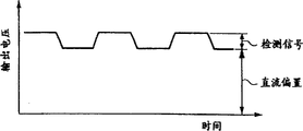
图3是本发明的磁编码装置的的输出波形图。
图4是表示本发明的磁编码装置的另一形态的斜视图。
图5是表示本发明的磁极检测用信号处理电路的电路图。
图6是表示现有例的主要部分的构成的斜视图。
图7是表示另一个现有例的主要部分的构成的斜视图。
具体实施方式
下面,根据附图说明本发明的实施例。
图1是表示本发明的磁阻型磁旋转编码器的外观的斜视图。在图1中,11是位置检测用传感器,13a~13c是检测电机的磁极位置的磁极位置检测用传感器,12是原点检测用磁传感器,21是偏置磁铁,用来对是原点检测用磁传感器12加上磁通,23a~23c是偏置磁铁,用来对是磁传感器13a~13c加上磁通,5是安装在移动体上由磁性材料形成的移动盘,6是取出磁传感器的信号并输出方波的信号处理电路。利用刻蚀等方法在移动盘5上形成位置检测用的狭缝磁道31、原点检测用的狭缝磁道32和磁极检测用的狭缝磁道33。当移动盘5旋转时,磁传感器的电阻值因有无狭缝引起的磁通的变化而变化,将该变化转换成电信号。进而,利用信号处理电路8对该电信号进行波形整形从而得到方波。这里,各狭缝磁道的配置也可以不用图1的配置,可以任意选择。
图2是表示本发明的磁编码装置的磁极检测部的图,图2(a)是表示磁传感器13的侧视截面图,图2(b)是表示磁极检测用的狭缝磁道33的局部平面图。图2中,23a是偏置磁铁,4是非磁性材料。狭缝磁道33由向外径方向突出的突出部331和空间部332形成。磁极检测用磁传感器13a在偏置磁铁23a的磁通的影响下,象图3所示的信号输出例那样输出直流偏置电压,检测信号受到该直流偏置电压的偏置而被检测出来。为使该直流偏置电压为某一值,配置非磁性材料4并设定其厚度。这里,非磁性材料4也可以是电路基板等中使用的环氧树脂。
图4是表示本发明的磁极检测用磁传感器13的构成的斜视图。在本实施形态中,作为3相6极电机之用狭缝旋转1圈被分割成每60度一份的6等份。在图4中,b1~b6是偏置磁铁,s1~s6是磁传感器,分别是U相、U*相、V相、V*相、W相、W*相。以U相磁传感器为基准,U*相磁传感器在-60度的位置,U*相磁传感器在-60度的位置,V*相磁传感器在+60度的位置,V*相磁传感器在-20度的位置,W*相磁传感器在-40度的位置,W*相磁传感器在+20度的位置,从而能够得到U*相信号是U相信号的倒相信号、V*相信号是V相信号的倒相信号、W*相信号是W相信号的倒相信号,而且U相、V相、W相信号间的相位差分别是120度。U相~W*相信号经磁极检测用的信号处理电路7进行差分放大后输入比较器,输出方波。
下面,说明输出方波的磁极检测用信号处理电路7。图5是磁极检测用信号处理电路7的电路图。在图5中,71是放大电路,72是差分放大电路,73是比较器。U相~W*相信号由放大电路711~716放大,该各信号在差分放大器721~723中,使U*相、V*相、W*相信号倒相后与U相、V相、W相相加,其输出信号由比较器73整形成方波,分别输出U相、V相、W相信号。这样,通过在1张移动盘上形成多个狭缝磁道,可以形成制造成本低、1张盘能得到多种信号的薄型磁编码器。此外,因与移动狭缝面内的狭缝磁道面对面地配置磁传感器,故可以使其径向尺寸减小。此外,与磁极的检测相关连地在磁传感器和偏置磁铁之间设置非磁性材料,通过调节非磁性材料的厚度可以得到适当的直流偏置,所以,能够得到信号振幅大了直流偏置这部分的检测信号,进而,利用差分放大能够得到抗温度变化能力强、抗噪声能力强的高性能的磁编码器。
(工业上利用的可能性)
如上所述,本发明的磁编码装置的制造成本低、体积小,适合于能得到的信号振幅大了直流偏置这部分的检测信号、进而利用差分放大能够对温度变化和噪声都有很强的抵抗能力的高性能的磁编码器。
Claims (1)
1、一种磁编码装置包括:
移动盘,所述移动盘由磁性材料形成,并具有在其圆周方向上排列的用于检测其位置的狭缝;
磁传感器,所述磁传感器与所述移动盘留有空隙;
偏置磁铁,每个所述偏置磁铁配置在各自的磁传感器的背面并且分别位于与各自的狭缝磁道对应的位置;和
信号处理电路,所述信号处理电路用于处理从上述磁传感器来的信号,
其特征在于上述移动盘包括:
磁极检测用的狭缝磁道,所述磁极检测用的狭缝磁道配置了用于检测电机磁极的狭缝,且位于其外缘部分,所述磁极检测用的狭缝具有突出到其外径的突出部分和凹槽部分,所述狭缝以等距离排列;
位置检测用的狭缝磁道,所述位置检测用的狭缝磁道配置了用于检测其位置的狭缝,且位于所述磁极检测用的狭缝磁道的内侧;以及
原点检测用的狭缝磁道,所述原点检测用的狭缝磁道配置了用于检测其原点位置的狭缝,且位于所述位置检测用的狭缝磁道的内侧,
且其中在每个上述磁传感器和提供给所述磁极检测用的狭缝磁道的偏置磁铁之间配置了非磁性材料。
Applications Claiming Priority (3)
| Application Number | Priority Date | Filing Date | Title |
|---|---|---|---|
| JP115214/1997 | 1997-04-16 | ||
| JP9115214A JPH10293042A (ja) | 1997-04-16 | 1997-04-16 | 磁気式エンコーダ装置 |
| JP115214/97 | 1997-04-16 |
Publications (2)
| Publication Number | Publication Date |
|---|---|
| CN1260871A CN1260871A (zh) | 2000-07-19 |
| CN1236285C true CN1236285C (zh) | 2006-01-11 |
Family
ID=14657198
Family Applications (1)
| Application Number | Title | Priority Date | Filing Date |
|---|---|---|---|
| CNB988061287A Expired - Fee Related CN1236285C (zh) | 1997-04-16 | 1998-04-10 | 磁编码装置 |
Country Status (7)
| Country | Link |
|---|---|
| US (1) | US6160499A (zh) |
| EP (1) | EP0977016B1 (zh) |
| JP (1) | JPH10293042A (zh) |
| KR (1) | KR100573461B1 (zh) |
| CN (1) | CN1236285C (zh) |
| DE (1) | DE69811652T2 (zh) |
| WO (1) | WO1998046968A1 (zh) |
Families Citing this family (23)
| Publication number | Priority date | Publication date | Assignee | Title |
|---|---|---|---|---|
| WO1999013296A1 (en) * | 1997-09-08 | 1999-03-18 | Kabushiki Kaisha Yaskawa Denki | Magnetic encoder |
| JP4269246B2 (ja) * | 2001-05-18 | 2009-05-27 | 株式会社安川電機 | エンコーダおよびエンコーダ付モータ |
| US6963064B2 (en) * | 2002-06-14 | 2005-11-08 | Pem Management, Inc. | Multi-resolution reflective optical incremental encoder |
| KR20060107516A (ko) * | 2003-10-24 | 2006-10-13 | 가부시키가이샤 야스카와덴키 | 자기식 인코더 장치 및 액츄에이터 |
| JP4286739B2 (ja) * | 2004-07-14 | 2009-07-01 | 三菱電機株式会社 | 磁気検出装置 |
| CN100390505C (zh) * | 2006-01-20 | 2008-05-28 | 安徽金海迪尔信息技术有限责任公司 | 绝对式多圈磁编码器 |
| EP2005118A2 (en) * | 2006-04-10 | 2008-12-24 | Timken US Corporation | Turning device position sensing system and method |
| JP5046850B2 (ja) * | 2007-10-22 | 2012-10-10 | 株式会社森精機製作所 | 位置検出装置、及び、バイアス磁界発生装置 |
| CN101876557B (zh) * | 2009-04-30 | 2013-03-06 | 浙江中科德润科技有限公司 | 位置检测装置及其信号处理方法 |
| CN101846531B (zh) * | 2010-05-28 | 2011-08-24 | 江苏斯沃特电气有限公司 | 多极复合式磁编码器 |
| CN102042840B (zh) * | 2010-09-07 | 2014-05-07 | 株洲威森机车配件有限公司 | 一种双路格雷码磁编码装置 |
| EP2642252A1 (en) | 2012-03-22 | 2013-09-25 | Schleifring und Apparatebau GmbH | Magnetic position encoder |
| WO2013176104A1 (ja) * | 2012-05-22 | 2013-11-28 | 三菱電機株式会社 | 磁気式回転角検出器 |
| CN102868279B (zh) * | 2012-09-12 | 2014-09-10 | 沈阳市蓝光自动化技术有限公司 | 低速电机磁旋转编码器 |
| CN103148774B (zh) * | 2013-03-11 | 2016-08-24 | 黎友盛 | 起重机大小车用座标式相对位移检测磁尺 |
| CN104333178B (zh) * | 2014-11-15 | 2017-08-22 | 欧佩德伺服电机节能系统有限公司 | 一种电机编码器转换连接结构的安装方法 |
| CN106052723B (zh) * | 2016-06-01 | 2019-12-27 | 江苏森尼克电子科技有限公司 | 一种磁编码器 |
| CN106767955A (zh) * | 2016-12-27 | 2017-05-31 | 江西省智成测控技术研究所有限责任公司 | 一种基于磁编码器的离轴式绝对角度测量的实现方法 |
| CN108768122B (zh) * | 2018-07-13 | 2025-03-28 | 深圳奥思添医疗科技有限公司 | Oct用直驱模组 |
| DE102020109534A1 (de) * | 2020-04-06 | 2021-10-07 | Hubtex Maschinenbau Gmbh & Co. Kg | Flurförderzeug mit Motor-Drehzahlerfassung und Asynchronmotor |
| DE102020117752A1 (de) * | 2020-07-06 | 2022-01-13 | Knorr-Bremse Systeme für Nutzfahrzeuge GmbH | Omnidirektionaler Drehzahl- und Richtungssensor |
| CN118575401A (zh) * | 2022-01-17 | 2024-08-30 | 日商鹰野株式会社 | 旋转驱动装置 |
| CN116381267B (zh) * | 2023-02-27 | 2026-04-14 | 西门子(中国)有限公司 | 传感器系统和利用其测量旋转轴的旋转参数的方法 |
Family Cites Families (11)
| Publication number | Priority date | Publication date | Assignee | Title |
|---|---|---|---|---|
| JPS5940856U (ja) * | 1982-09-06 | 1984-03-15 | 富士重工業株式会社 | 回転数検出器 |
| GB8322886D0 (en) * | 1983-08-25 | 1983-09-28 | Lucas Ind Plc | Transducer means |
| JPH0552584A (ja) * | 1991-08-28 | 1993-03-02 | Toshiba Corp | 磁気式エンコーダ |
| US5444370A (en) * | 1993-03-18 | 1995-08-22 | Honeywell Inc. | Magnetic angular position sensor with two magnetically sensitive components arranged proximate two target tracks having complimentary magnetic and nonmagnetic segments |
| GB9311694D0 (en) * | 1993-06-07 | 1993-07-21 | Switched Reluctance Drives Ltd | Electric machine rotor prosition encoder |
| JPH0731116A (ja) * | 1993-07-06 | 1995-01-31 | Matsushita Electric Ind Co Ltd | ブラシレスモータ用磁気式エンコーダ |
| JPH0743375A (ja) * | 1993-07-30 | 1995-02-14 | Matsushita Electric Works Ltd | 回転検出装置 |
| DE4333800A1 (de) * | 1993-10-04 | 1995-04-06 | Deutsche Automobilgesellsch | Vorrichtung zur Drehwinkeldetektierung |
| JPH07209315A (ja) * | 1994-01-26 | 1995-08-11 | Mitsubishi Electric Corp | 電磁式回転センサ |
| DE19513692C1 (de) * | 1995-04-11 | 1996-07-18 | Stegmann Max Antriebstech | Drehwinkelmeßsystem |
| US5774074A (en) * | 1997-01-21 | 1998-06-30 | Hewlett-Packard Company | Multi-track position encoder system |
-
1997
- 1997-04-16 JP JP9115214A patent/JPH10293042A/ja active Pending
-
1998
- 1998-04-10 DE DE69811652T patent/DE69811652T2/de not_active Expired - Fee Related
- 1998-04-10 KR KR1019997009400A patent/KR100573461B1/ko not_active Expired - Fee Related
- 1998-04-10 CN CNB988061287A patent/CN1236285C/zh not_active Expired - Fee Related
- 1998-04-10 EP EP98912772A patent/EP0977016B1/en not_active Expired - Lifetime
- 1998-04-10 US US09/402,884 patent/US6160499A/en not_active Expired - Fee Related
- 1998-04-10 WO PCT/JP1998/001677 patent/WO1998046968A1/ja not_active Ceased
Also Published As
| Publication number | Publication date |
|---|---|
| EP0977016A4 (en) | 2000-07-05 |
| EP0977016A1 (en) | 2000-02-02 |
| KR100573461B1 (ko) | 2006-04-24 |
| DE69811652D1 (de) | 2003-04-03 |
| WO1998046968A1 (en) | 1998-10-22 |
| EP0977016B1 (en) | 2003-02-26 |
| DE69811652T2 (de) | 2003-09-18 |
| KR20010006316A (ko) | 2001-01-26 |
| CN1260871A (zh) | 2000-07-19 |
| US6160499A (en) | 2000-12-12 |
| JPH10293042A (ja) | 1998-11-04 |
Similar Documents
| Publication | Publication Date | Title |
|---|---|---|
| KR100573461B1 (ko) | 자기식 엔코더장치 | |
| CN101443632B (zh) | 磁性编码装置 | |
| US7028545B2 (en) | Position sensor, designed in particular for detecting a steering column torsion | |
| CN1243956C (zh) | 磁编码装置 | |
| US4594548A (en) | Multi phase magnetic sensor apparatus for detecting the position of moving member | |
| GB2083955A (en) | Brushless dc motor | |
| EP3982089B1 (en) | Magnetic sensor system for motor control | |
| EP1371937B1 (en) | Rotating angle detector and device using the detector | |
| JP2000065596A5 (ja) | 磁気式エンコーダおよび磁気式エンコーダ付モータ | |
| JP2001033277A5 (ja) | 磁気式エンコーダおよび磁気式エンコーダ付モータ | |
| JPWO2007055135A1 (ja) | 磁気式エンコーダ装置 | |
| WO2009084346A1 (ja) | 磁気式エンコーダ装置 | |
| EP4235108B1 (en) | Magnetic position sensor system with high accuracy | |
| JPH10185621A (ja) | 磁気式エンコーダ装置 | |
| JP2013257158A (ja) | エンコーダ、符号板、位置情報検出センサ、駆動装置、及びロボット装置 | |
| JPS61189166A (ja) | 磁電素子付き小型電動機 | |
| JPS63305211A (ja) | 絶対位置が判明する磁気エンコ−ダ | |
| JP5050817B2 (ja) | 磁気式エンコーダ | |
| JPH0723690Y2 (ja) | 磁気エンコーダの信号処理回路 | |
| JPH03191820A (ja) | 磁気エンコーダ | |
| JPS61189414A (ja) | 磁束密度変化検知装置 | |
| JPH03191821A (ja) | 磁気エンコーダ | |
| JPH03191819A (ja) | 磁気エンコーダ | |
| JPH0158750B2 (zh) | ||
| JPH03191823A (ja) | 磁気エンコーダ |
Legal Events
| Date | Code | Title | Description |
|---|---|---|---|
| C06 | Publication | ||
| PB01 | Publication | ||
| C10 | Entry into substantive examination | ||
| SE01 | Entry into force of request for substantive examination | ||
| C14 | Grant of patent or utility model | ||
| GR01 | Patent grant | ||
| C17 | Cessation of patent right | ||
| CF01 | Termination of patent right due to non-payment of annual fee |
Granted publication date: 20060111 Termination date: 20100410 |