CN1237279C - Electric compressor and its control method - Google Patents
Electric compressor and its control method Download PDFInfo
- Publication number
- CN1237279C CN1237279C CNB021262993A CN02126299A CN1237279C CN 1237279 C CN1237279 C CN 1237279C CN B021262993 A CNB021262993 A CN B021262993A CN 02126299 A CN02126299 A CN 02126299A CN 1237279 C CN1237279 C CN 1237279C
- Authority
- CN
- China
- Prior art keywords
- motor
- compressor
- rotor
- predetermined
- torque
- Prior art date
- Legal status (The legal status is an assumption and is not a legal conclusion. Google has not performed a legal analysis and makes no representation as to the accuracy of the status listed.)
- Expired - Fee Related
Links
- 238000000034 method Methods 0.000 title claims description 37
- 239000003507 refrigerant Substances 0.000 claims description 32
- 238000011156 evaluation Methods 0.000 claims description 11
- 238000001514 detection method Methods 0.000 claims description 4
- 238000007906 compression Methods 0.000 description 35
- 230000006835 compression Effects 0.000 description 34
- 238000005057 refrigeration Methods 0.000 description 19
- 239000003795 chemical substances by application Substances 0.000 description 17
- 230000000694 effects Effects 0.000 description 11
- 239000007788 liquid Substances 0.000 description 11
- 238000005516 engineering process Methods 0.000 description 4
- 238000007599 discharging Methods 0.000 description 3
- 241000632678 Spirotheca Species 0.000 description 2
- 238000010586 diagram Methods 0.000 description 2
- 230000005611 electricity Effects 0.000 description 2
- 238000012544 monitoring process Methods 0.000 description 2
- 230000002093 peripheral effect Effects 0.000 description 2
- 239000006200 vaporizer Substances 0.000 description 2
- 238000004804 winding Methods 0.000 description 2
- XEEYBQQBJWHFJM-UHFFFAOYSA-N Iron Chemical group [Fe] XEEYBQQBJWHFJM-UHFFFAOYSA-N 0.000 description 1
- 230000000295 complement effect Effects 0.000 description 1
- 230000005494 condensation Effects 0.000 description 1
- 238000009833 condensation Methods 0.000 description 1
- 238000001816 cooling Methods 0.000 description 1
- 230000008878 coupling Effects 0.000 description 1
- 238000010168 coupling process Methods 0.000 description 1
- 238000005859 coupling reaction Methods 0.000 description 1
- 238000001704 evaporation Methods 0.000 description 1
- 230000008020 evaporation Effects 0.000 description 1
- 230000010354 integration Effects 0.000 description 1
Images


Classifications
-
- F—MECHANICAL ENGINEERING; LIGHTING; HEATING; WEAPONS; BLASTING
- F04—POSITIVE - DISPLACEMENT MACHINES FOR LIQUIDS; PUMPS FOR LIQUIDS OR ELASTIC FLUIDS
- F04B—POSITIVE-DISPLACEMENT MACHINES FOR LIQUIDS; PUMPS
- F04B49/00—Control, e.g. of pump delivery, or pump pressure of, or safety measures for, machines, pumps, or pumping installations, not otherwise provided for, or of interest apart from, groups F04B1/00 - F04B47/00
- F04B49/06—Control using electricity
-
- F—MECHANICAL ENGINEERING; LIGHTING; HEATING; WEAPONS; BLASTING
- F04—POSITIVE - DISPLACEMENT MACHINES FOR LIQUIDS; PUMPS FOR LIQUIDS OR ELASTIC FLUIDS
- F04B—POSITIVE-DISPLACEMENT MACHINES FOR LIQUIDS; PUMPS
- F04B49/00—Control, e.g. of pump delivery, or pump pressure of, or safety measures for, machines, pumps, or pumping installations, not otherwise provided for, or of interest apart from, groups F04B1/00 - F04B47/00
- F04B49/06—Control using electricity
- F04B49/065—Control using electricity and making use of computers
-
- F—MECHANICAL ENGINEERING; LIGHTING; HEATING; WEAPONS; BLASTING
- F04—POSITIVE - DISPLACEMENT MACHINES FOR LIQUIDS; PUMPS FOR LIQUIDS OR ELASTIC FLUIDS
- F04B—POSITIVE-DISPLACEMENT MACHINES FOR LIQUIDS; PUMPS
- F04B27/00—Multi-cylinder pumps specially adapted for elastic fluids and characterised by number or arrangement of cylinders
- F04B27/08—Multi-cylinder pumps specially adapted for elastic fluids and characterised by number or arrangement of cylinders having cylinders coaxial with, or parallel or inclined to, main shaft axis
- F04B27/0873—Component parts, e.g. sealings; Manufacturing or assembly thereof
- F04B27/0895—Component parts, e.g. sealings; Manufacturing or assembly thereof driving means
-
- F—MECHANICAL ENGINEERING; LIGHTING; HEATING; WEAPONS; BLASTING
- F04—POSITIVE - DISPLACEMENT MACHINES FOR LIQUIDS; PUMPS FOR LIQUIDS OR ELASTIC FLUIDS
- F04C—ROTARY-PISTON, OR OSCILLATING-PISTON, POSITIVE-DISPLACEMENT MACHINES FOR LIQUIDS; ROTARY-PISTON, OR OSCILLATING-PISTON, POSITIVE-DISPLACEMENT PUMPS
- F04C18/00—Rotary-piston pumps specially adapted for elastic fluids
- F04C18/02—Rotary-piston pumps specially adapted for elastic fluids of arcuate-engagement type, i.e. with circular translatory movement of co-operating members, each member having the same number of teeth or tooth-equivalents
- F04C18/0207—Rotary-piston pumps specially adapted for elastic fluids of arcuate-engagement type, i.e. with circular translatory movement of co-operating members, each member having the same number of teeth or tooth-equivalents both members having co-operating elements in spiral form
- F04C18/0215—Rotary-piston pumps specially adapted for elastic fluids of arcuate-engagement type, i.e. with circular translatory movement of co-operating members, each member having the same number of teeth or tooth-equivalents both members having co-operating elements in spiral form where only one member is moving
-
- F—MECHANICAL ENGINEERING; LIGHTING; HEATING; WEAPONS; BLASTING
- F04—POSITIVE - DISPLACEMENT MACHINES FOR LIQUIDS; PUMPS FOR LIQUIDS OR ELASTIC FLUIDS
- F04C—ROTARY-PISTON, OR OSCILLATING-PISTON, POSITIVE-DISPLACEMENT MACHINES FOR LIQUIDS; ROTARY-PISTON, OR OSCILLATING-PISTON, POSITIVE-DISPLACEMENT PUMPS
- F04C28/00—Control of, monitoring of, or safety arrangements for, pumps or pumping installations specially adapted for elastic fluids
-
- F—MECHANICAL ENGINEERING; LIGHTING; HEATING; WEAPONS; BLASTING
- F04—POSITIVE - DISPLACEMENT MACHINES FOR LIQUIDS; PUMPS FOR LIQUIDS OR ELASTIC FLUIDS
- F04C—ROTARY-PISTON, OR OSCILLATING-PISTON, POSITIVE-DISPLACEMENT MACHINES FOR LIQUIDS; ROTARY-PISTON, OR OSCILLATING-PISTON, POSITIVE-DISPLACEMENT PUMPS
- F04C28/00—Control of, monitoring of, or safety arrangements for, pumps or pumping installations specially adapted for elastic fluids
- F04C28/08—Control of, monitoring of, or safety arrangements for, pumps or pumping installations specially adapted for elastic fluids characterised by varying the rotational speed
-
- F—MECHANICAL ENGINEERING; LIGHTING; HEATING; WEAPONS; BLASTING
- F04—POSITIVE - DISPLACEMENT MACHINES FOR LIQUIDS; PUMPS FOR LIQUIDS OR ELASTIC FLUIDS
- F04C—ROTARY-PISTON, OR OSCILLATING-PISTON, POSITIVE-DISPLACEMENT MACHINES FOR LIQUIDS; ROTARY-PISTON, OR OSCILLATING-PISTON, POSITIVE-DISPLACEMENT PUMPS
- F04C29/00—Component parts, details or accessories of pumps or pumping installations, not provided for in groups F04C18/00 - F04C28/00
- F04C29/0042—Driving elements, brakes, couplings, transmissions specially adapted for pumps
- F04C29/0085—Prime movers
-
- F—MECHANICAL ENGINEERING; LIGHTING; HEATING; WEAPONS; BLASTING
- F04—POSITIVE - DISPLACEMENT MACHINES FOR LIQUIDS; PUMPS FOR LIQUIDS OR ELASTIC FLUIDS
- F04B—POSITIVE-DISPLACEMENT MACHINES FOR LIQUIDS; PUMPS
- F04B2203/00—Motor parameters
- F04B2203/02—Motor parameters of rotating electric motors
- F04B2203/0207—Torque
-
- F—MECHANICAL ENGINEERING; LIGHTING; HEATING; WEAPONS; BLASTING
- F04—POSITIVE - DISPLACEMENT MACHINES FOR LIQUIDS; PUMPS FOR LIQUIDS OR ELASTIC FLUIDS
- F04B—POSITIVE-DISPLACEMENT MACHINES FOR LIQUIDS; PUMPS
- F04B2203/00—Motor parameters
- F04B2203/02—Motor parameters of rotating electric motors
- F04B2203/0209—Rotational speed
-
- F—MECHANICAL ENGINEERING; LIGHTING; HEATING; WEAPONS; BLASTING
- F04—POSITIVE - DISPLACEMENT MACHINES FOR LIQUIDS; PUMPS FOR LIQUIDS OR ELASTIC FLUIDS
- F04C—ROTARY-PISTON, OR OSCILLATING-PISTON, POSITIVE-DISPLACEMENT MACHINES FOR LIQUIDS; ROTARY-PISTON, OR OSCILLATING-PISTON, POSITIVE-DISPLACEMENT PUMPS
- F04C2270/00—Control; Monitoring or safety arrangements
- F04C2270/03—Torque
Landscapes
- Engineering & Computer Science (AREA)
- Mechanical Engineering (AREA)
- General Engineering & Computer Science (AREA)
- Manufacturing & Machinery (AREA)
- Computer Hardware Design (AREA)
- Control Of Positive-Displacement Pumps (AREA)
- Applications Or Details Of Rotary Compressors (AREA)
- Control Of Motors That Do Not Use Commutators (AREA)
- Rotary Pumps (AREA)
- Control Of Electric Motors In General (AREA)
- Control Of Ac Motors In General (AREA)
Abstract
When an electric compressor is activated, initial current data is selected by a selector, and a motor is driven with the torque corresponding to the initial current data. When the motor is driven by a 1/2 turn, the selector selects current difference data. The current difference data corresponds to an instructed speed. After the switch of the selector, the motor is driven to rotate at the instructed speed.
Description
Technical field
The present invention relates to a kind of controlling method of controlling motor compressor, relate in particular to a kind of method of controlling the motor of motor compressor setting.
Background technique
Motor compressor uses widely in various occasions, for example aircondition, refrigerator etc.
Motor compressor is provided with a motor, and rotatablely moves compressed refrigerant to obtain cooling capacity by motor.Motor is so controlled, and for example it can be based on the temperature of user's regulation and the difference between the current actual temperature etc. by the constant speed operation.
By using the position transducer such as hall device etc., motor speed (rotating speed) can be controlled by the position of monitoring rotor basically.Yet in motor compressor, what need is to use a kind of control system of controlling motor speed, this system is not by the use position sensor, but by the position (middle finger does not have sensing system hereinafter) based on estimation motors such as the electromotive force of motor, electric currents.Usually in no sensing system, rotating speed is given as control command value, and motor so controls, i.e. actual speed and this control command value coupling.
Yet,, can liquefy and stay in compressor at the gaseous form refrigeration agent during the compressor operating subsequently if compressor is in non-operating state for a long time.When compressor is driven under this state, motor needs big torque.In the system of no sensor, particularly given as control command value when desired speed, and will be driven according to this control command value motor the time, need very big torque, and motor is driven asynchronously sometimes.In addition, this very big torque also needs jumbo negative circuit.
The method that solves the problem of above-mentioned motor compressor is described in the Japanese patent application for the spy opens flat No.6-241183 (USP 5518373) of publication number for example.The motor compressor of describing in this official gazette is by making when the starting motor motor with one section preset time of step mode operation, discharging liquid refrigeration agent, and enters normal operation mode subsequently.Yet this method of describing in this official gazette uses the long period to discharge liquid refrigerant.And, though some other methods also are introduced in this official gazette, but have compressor huge, liquid refrigerant can not be got rid of fully, and compressor itself also vibrates, or the like problem.
Summary of the invention
The present invention is directed to provides a kind of method of controlling motor compressor, thereby when preventing the motor asynchronous operation, drive motor efficiently.
Method of the present invention is, control one is provided with the motor compressor of motor, and this compressor is used for compressed refrigerant, and this method may further comprise the steps: with predetermined torque actuated motor, rotate through a predetermined rotating amount up to the rotor of motor; After rotor rotates through this predetermined rotating amount, with a predetermined speed driving motor.
When motor compressor was in non-operating state for a long time, the refrigeration agent of gaseous form can liquefy in the compressor operating process, and is trapped in the compressor.When this compressor starts under this state, very large load will be applied on the motor.
The method according to this invention, when motor compressor started, motor was driven with a predetermined torque, and residual refrigeration agent is owing to the operation of motor is discharged.When motor is driven and when rotating through a predetermined rotating amount, suppose that residual refrigeration agent has been discharged from, and motor driven rotation with a predetermined speed.
If when motor compressor starts, there is not the liquid refrigerant of delay, then the load of motor is slight.If therefore motor is driven with pre-determined torque, it will be driven and be rotated through a predetermined rotating amount in the short period of time.Like this, in the short period after motor compressor starts, motor can a predetermined speed be driven rotation.
On the other hand, when motor compressor starts, the liquid refrigerant of delay is arranged, then the load of motor is heavy.Therefore, when motor was driven with pre-determined torque, revolution was slow, but asynchronous operation is avoided.
In method of the present invention on the other hand, when motor compressor started, the initial position of motor rotor was estimated or detect.One side again in method of the present invention when motor compressor starts, with this motor of constant torque mode activated, rotates through predetermined rotating amount up to this rotor; And when this rotor is driven when rotating through predetermined rotating amount from initial position with the constant torque pattern, with the operating mode of motor from the constant torque mode switch to constant speed mode.In these methods, can obtain similar effect by above-mentioned functions.
Description of drawings
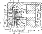
Fig. 1 is the sectional view according to the motor compressor of the embodiment of the invention;
Fig. 2 is the skeleton diagram that is used to drive the control system of the motor that motor compressor is provided with;
Fig. 3 is the flow chart of the operation of controller;
Fig. 4 shows the circuit that is used for drive motor;
Fig. 5 is according to the sectional view of the motor compressor of second embodiment of the invention; With
Fig. 6 A and 6B show the relation between piston position and the refrigeration agent discharge.
Embodiment
With reference to accompanying drawing embodiments of the invention are carried out following description.
Fig. 1 is the sectional view of the electric scroll formula compressor of the embodiment of the invention.This motor compressor comprises motor 1 and compression unit 2.The housing of motor compressor comprises fixed scroll 3, central enclosure 4 and motor casing 5.Fixed scroll 3 comprises fixed charge method end plate 3a and the fixedly spiral wall 3b that extends from fixed charge method end plate 3a.
Motor 1 comprises axle 11, rotor 12, stator 13 etc.Axle 11 is supported by central enclosure 4 and the motor casing 5 that has bearing 14,15.Eccentric shaft 11a forms at the place, end of axle 11.Rotor 12 is fixed on the axle 11, and synchronously rotates with axle 11.Stator 13 is provided with around rotor 12.Stator 13 is provided with a plurality of salient poles, around each salient pole winding around.The coil that centers on each salient pole winding of stator 13 in use is U, V, W phase coil.
Motor 1 is by battery 21 supplying power.DC electrical source output from battery 21 changes Ac into by inverter 22, and is supplied to motor 1.Inverter 22 is controlled by controller 23.
When motor 1 operation of above-mentioned structure and eccentric shaft 11a rotation, activity scroll 32 is rotated.Although do not explain particularly that motor compressor is provided with a structure, to be used to preventing that activity scroll 32 is around its axis generation rotation.
External refrigerant loop (refrigeration cycle) 41 is provided with condenser, vaporizer etc.; The external refrigerant loop makes the refrigerant gas of discharging from compression unit 2 carry out condensation process and evaporation process; And make refrigerant gas be circulated back to compression unit 2.
In this motor compressor, when motor 1 operation, axle 11 rotations, and activity scroll 32 is rotated.When activity scroll 32 was rotated, the compression chamber 34 at the peripheral place of spiral wall 3b, 32b moved to spiral wall 3b, 32b inner periphery, and the volume of compression chamber 34 reduces thereupon.Its result is, is brought in the compression chamber 34 refrigeration agent by compression, and compressed subsequently refrigeration agent is discharged in the external refrigerant loop 41 through exhaust port 36.
As mentioned above, this motor compressor is provided with a plurality of compression chambers 34.By drive motor 1, above-mentioned suction process, compression process and discharge process are sequentially carried out in each compression chamber 34.
When this motor compressor stops its when operation, refrigerant gas can be stayed in a plurality of compression chambers 34 at least one usually.If this refrigeration agent is detained for a long time, it can liquefy.That is to say that this motor compressor is in non-operating state for a long time, the refrigeration agent of liquefaction can be trapped in the compression chamber 34.So, when this motor compressor starts, must at first discharge the refrigeration agent of liquefaction.
Fig. 2 is the skeleton diagram that is used to drive the control system of the motor 1 that is provided with into motor compressor.According to present embodiment, suppose that motor 1 controlled by the method for no sensor.That is to say that motor 1 is not provided with a position transducer (this rotor is corresponding to the rotor 12 of Fig. 1) that is used for direct detection rotor position, and the position of this rotor is estimated based on current waveform, back emf waveform etc.
Torque mode control unit 52 produces a control signal, and it is used for given torque drive motor 1, and this unit transmits the signal to inverter 22.The torque of motor 1 be supplied to the electric current of motor 1 proportional.On the other hand, velocity mode control unit 53 produces a control signal, and it is used for specific speed (rotating speed) drive motor 1, and this unit transmits the signal to inverter 22.
According to the control signal that is produced by controller 23, inverter 22 produces 3 cross streams electricity, and it is supplied to motor 1.Motor 1 is by the electric driving of 3 cross streams that provided by inverter 22 subsequently.
According to present embodiment, motor 1 uses the method for no sensor to control.Yet the present invention does not repel by using position transducer such as hall device etc. to control the configuration of motor 1.
Fig. 3 is the operational flowchart of controller 23.When motor compressor starts, will carry out this process in this flow chart.
In step S1, the initial position of rotor of estimation (or detection) motor 1.In the system of no sensor, the method for estimation initial position of rotor can obtain in known technology.In the system of no sensor, the method for estimation initial position of rotor for example is described in following text.
(1) reel number of publishing 1996 the 7th phases is 116-D (Vol.116-D, No.7,1996), the author is Takeshita, Ichikawa, Matsui, Yamada, the NEC engineer research institute research paper of andMizutani (Research Paper ofInstitute of Electrical Engineers of Japan) " in the estimation (Initial RotorPosition Estimation of Sensorless Salient-Pole Brushless DCMotor) of the salient pole brushless DC motor rotor initial position of no sensor ".
(2) at national meeting (the National Convention of Institute of Electrical EngineersIndustrial Application of 1995-1996 electrical engineer research institute commercial Application, 180,195 (1995-1996)) disclosed, author is " the Evaluation of Estimation Precision in PMMotor Position Sensorless Field Magnetic Pole DetectingMethod using Current Vector Locus " of Nishida and Kondoh.
In step S2, produce a control signal, it is used for predetermined constant torque drive motor 1.The torque of motor 1 be supplied to the electric current of motor 1 roughly proportional.So in step S2, produce a control signal, it is used to be supplied to the predetermined steady current of motor 1." predetermined steady current " for example refers to the maximum rated current of motor 1.
In step S3, the rotor-position of estimation motor 1.This method of the rotor-position of the operating motor of estimation can obtain from known technology in the system of no sensor.
In step S4, check from estimation or detected initial position among step S1 whether to rotate to the rotating amount of the current location that in step S4, is estimated to above a predetermined rotating amount." predetermined rotating amount " is for example 1/2 commentaries on classics herein, yet is not limited to this rotating amount.Then, motor 1 is driven with constant torque, and surpassing 1/2 up to the rotor of motor 1 from the rotating amount of initial position changes.
Surpass 1/2 when changeing when motor 1 is actuated to rotation, the operating mode of motor 1 from the constant torque mode switch to constant speed mode, after this with constant speed mode drive motor 1.Constant speed mode is an operating mode, and wherein motor 1 is by specific speed (rotating speed) running.
In the process shown in the flow chart, when being subjected to drive in the scheduled time that starts from motor compressor to rotate 1/2, do not change the rotor of motor 1, and the driving operation of motor 1 is stopped.
Like this, in the motor compressor of the embodiment of the invention, when motor compressor started, motor 1 was driven with predetermined torque.Then, activity scroll 32 is rotated, and the refrigeration agent of staying in the compression chamber 34 is discharged in the external refrigerant loop 41 through exhaust port 36.
If there is not liquid refrigerant to be trapped in the compression chamber 34, the load that is used for rotation activity scroll 32 so is slight.So, if motor 1 is driven with pre-determined torque, motor 1 can rotate at short notice 1/2 change more than.Subsequently the operating mode of motor 1 at once from the constant torque mode switch to constant speed mode.That is to say that in this case, motor 1 only is driven with the constant torque pattern at short notice.
On the other hand, if liquid refrigerant is trapped in the compression chamber 34, the load that is used for rotation activity scroll 32 so is heavy.So if motor 1 is driven with pre-determined torque, motor 1 rotates lentamente.Its result is though will exhaust considerable time more than making motor 1 rotation 1/2 commentaries on classics, will avoid motor that operation asynchronously takes place.
According to present embodiment, when motor 1 rotates 1/2 when changeing above, the operating mode of motor 1 from the constant torque mode switch to constant speed mode.Yet the invention is not restricted to this value.That is to say that the rotating amount of motor 1 is set at a numerical value, this rotating amount that is used to change the motor operation pattern is determined, and liquid refrigerant is discharged from compression chamber 34 by the rotation of activity scroll 32 when satisfying this numerical value.
Fig. 4 shows the circuit that is used for drive motor 1.This circuit is corresponding to the controller 23 shown in Fig. 1 or 2.
Under the instruction from rotation detecting circuit 64, a selector 62 is selected one of them of current differential data and initial current data.The current differential data are meant the instruction current data that calculated by speed control unit 61 and by detected the difference between the motor current data that the electric current that is supplied to motor 1 obtains by current sensor 65.The initial current data are meant maximum rated current or the corresponding current value of maximum rated torque with motor 1.
When motor compressor started, rotation detecting circuit 64 was sent an instruction to selector 62, to select the initial current data.It also estimates the rotor-position of motor 1, and estimated value is stored as the initial position data.Subsequently, when exporting the position data of estimation by evaluation unit 51, rotation detecting circuit 64 is calculated the rotating amount of the rotor of motors 1 from its initial position.When rotation detecting circuit 64 detects: motor 1 has been subjected to drive to rotate and has surpassed a prearranging quatity, and it sends an instruction to selector 62, to select the current differential data.
Being described below of this control operation.That is to say that when motor compressor started, selector 62 was selected the initial current data.Therefore motor 1 is by a torque actuated corresponding to the initial current data.When motor 1 was actuated to rotate a predetermined rotating amount (for example 1/2 changes), selector 62 was selected the current differential data.Therefore motor 1 is actuated to the speed rotation corresponding to the command speed data.That is to say, the operating mode of motor 1 from the constant torque mode switch to constant speed mode.
In the above-described embodiments, swirl motor compressor has been described.Yet the present invention is not limited to this application, but can be applicable in for example electronic oblique tray type compressor.
Fig. 5 is the sectional view of the electronic oblique tray type compressor of second embodiment of the invention.This motor compressor also comprises motor 1 and compression unit 2.
Motor 1 comprises running shaft 101, magnet 102, schedules iron core 103, coil 104 etc.Magnet 102 is one to be fixed to the rotor on the running shaft 101, and this magnet and running shaft 101 rotate synchronously.Stator core 103 is arranged to around magnet 102.Be provided with a plurality of (for example nine) stator core 103 herein.In addition, coil 104 (for example U, V, W phase coil) twines around each stator core 103.
Compression unit 2 comprises running shaft 11, wobbler 112, cylinder hole 113, piston 114 etc.Running shaft 111 is connected with the running shaft 101 of motor 1, and running shaft 111 rotates synchronously with running shaft 101 when motor 1 running.Wobbler 112 is supported, with the rotation synchronously with the rotation of running shaft 111.A plurality of cylinders hole 113 forms around running shaft 111.In Fig. 5, only show a cylinder hole.Piston 114 is connected on the swash plate 112 through crawler shoe 116, and piston is contained in the cylinder hole 113, thereby makes rotatablely moving of swash plate 112 cause the reciprocating linear motion of piston 114.
In this motor compressor, when motor 1 running, running shaft 111 rotates synchronously with motor 1.Rotatablely moving of running shaft 111 is transformed into the reciprocating linear motion of piston 114 by swash plate 112 and crawler shoe 116.At this moment, the volume of compression chamber 115 changes according to the position of piston 114 in cylinder hole 113.That is to say, when piston 114 is in lower dead point position, the volume maximum of compression chamber 115, and when it is in upper dead center position, the volume minimum of compression chamber 115.
Refrigerant gas supplies to suction chamber 121 from external refrigerant loop 41.When piston 114 when upper dead center starting moves to lower dead centre, refrigerant gas from suction chamber 121 through suction valve 122 suction compression chambers 115.When piston 114 when lower dead centre moves to upper dead center, the refrigerant gas of suction compression chamber 115 is compressed.When the pressure in compression chamber 115 was increased to a predetermined value, refrigerant compressed gas was discharged to discharge side 124 through expulsion valve 123.The refrigerant gas that is discharged to discharge side 124 is circulated back to suction chamber 121 through external refrigerant loop (refrigeration cycle) 41.
When the operation of this motor compressor stopped, refrigerant gas may be trapped in the compression chamber 115 as the case may be.So when this motor compressor started, the situation of scroll compressor as shown in Figure 1 was the same, must discharge the liquid refrigerant that in compression chamber 115, is detained.
Fig. 6 A and 6B show the relation between piston position and the discharging refrigerant.As shown in Figure 6A, if piston 114 is in lower dead centre when motor compressor starts, then is trapped in refrigeration agent in the compression chamber 115 and moves to upper dead center shown in Fig. 6 B by piston 114 and discharge.Suppose when motor 1 and revolve and turn around that piston 114 is done a to-and-fro motion, motor 1 is rotated 1/2 to be changeed piston 114 is moved to the position shown in Fig. 6 B from as shown in Figure 6A position.That is to say that in this case, only rotate 1/2 commentaries on classics if motor 1 is subjected to drive, refrigeration agent is then discharged like this from compression chamber 115.On the other hand, piston 114 does not have refrigeration agent to stay in the compression chamber 115 at upper dead center so when motor compressor starts.So, these situations are taken into account, if being driven to rotate 1/2, motor 1 changes, regardless of the position of the piston 114 of this motor compressor, refrigeration agent is then discharged from compression chamber 115 basically.
Yet, fully to discharge for the refrigeration agent that will be trapped in the compression chamber 115, motor 1 is driven with the constant torque pattern, finishes a to-and-fro motion up to piston 114.
In addition, in above-mentioned this embodiment, when motor compressor started, motor 1 was driven with the constant torque pattern.Yet the present invention is not limited to this application.That is to say that when motor compressor started, motor 1 was by a torque actuated of setting Control Parameter for, and with constant torque drive motor 1 not necessarily.
In addition, in above-mentioned this embodiment, after liquid refrigerant was discharged from, motor 1 was driven with constant speed mode.Yet the present invention is not limited to this application.That is to say that motor 1 is driven with a speed of setting Control Parameter for, and with constant speed drive motor 1 not necessarily.
In addition, in above-mentioned this embodiment, the initial position of rotor of motor 1 goes out according to known technology is estimated.Yet the present invention is not limited to this feature.That is to say that the electric current of a predefined type (pattern) is applied to U, the V of motor 1, W phase place, and controlled the making forcibly with position corresponding to the type of rotor is complementary.For this method, claimant of the present invention has submitted a patent application (patent application JP-2001-74499) to.
In addition, the foregoing description is based on the system of no sensor, but the present invention is not limited to this.That is to say that the present invention can be applicable to use the direct control system that detect the rotor-position of motor 1 such as hall device.
According to the present invention, when motor compressor started, the liquid refrigerant of delay was discharged from, and motor can asynchronous operation.In the shortest time, motor can enter normal operation mode.
Claims (5)
1. method that is used to control the motor compressor that has motor, this compressor is used for compressed refrigerant, and this method comprises:
With predetermined torque actuated motor, rotate through a predetermined rotating amount up to the rotor of described motor; With
After described rotor rotates through this predetermined rotating amount, with a predetermined speed driving motor.
2. the method for claim 1 is characterized in that, it also comprises:
When described motor compressor starts, the initial position of the rotor of estimation or detection motor.
3. the method for claim 1 is characterized in that, it also comprises:
When described motor compressor starts,, rotate through this predetermined rotating amount up to this rotor with this motor of constant torque mode activated; With
When this rotor is driven when rotating through predetermined rotating amount from initial position with the constant torque pattern, with the operating mode of motor from the constant torque mode switch to constant speed mode.
4. motor compressor that has motor, it is used for compressed refrigerant, and this compressor comprises,
One controller, this controller comprises:
Evaluation unit, the initial position of the rotor of this motor is estimated or detected to this evaluation unit when described motor compressor starts;
The torque mode control unit, it is with predetermined this motor of torque actuated; With
The velocity mode control unit, the instruction of this rotor acquisition torque mode control unit was subjected to the predetermined excessively rotating amount of rotary driving from initial position after, this velocity mode control unit drove this motor at a predetermined velocity.
5. motor compressor as claimed in claim 4 is characterized in that it also comprises:
The flow through electric current of motor of current detecting unit, its detection,
Wherein, described motor is based on being driven by the detected electric current of described current detecting unit.
Applications Claiming Priority (3)
| Application Number | Priority Date | Filing Date | Title |
|---|---|---|---|
| JP218451/01 | 2001-07-18 | ||
| JP2001218451A JP4075338B2 (en) | 2001-07-18 | 2001-07-18 | Control method of electric compressor |
| JP218451/2001 | 2001-07-18 |
Publications (2)
| Publication Number | Publication Date |
|---|---|
| CN1397736A CN1397736A (en) | 2003-02-19 |
| CN1237279C true CN1237279C (en) | 2006-01-18 |
Family
ID=19052627
Family Applications (1)
| Application Number | Title | Priority Date | Filing Date |
|---|---|---|---|
| CNB021262993A Expired - Fee Related CN1237279C (en) | 2001-07-18 | 2002-07-18 | Electric compressor and its control method |
Country Status (6)
| Country | Link |
|---|---|
| US (1) | US6869272B2 (en) |
| EP (1) | EP1277959B1 (en) |
| JP (1) | JP4075338B2 (en) |
| KR (1) | KR100461615B1 (en) |
| CN (1) | CN1237279C (en) |
| BR (1) | BR0202696A (en) |
Families Citing this family (54)
| Publication number | Priority date | Publication date | Assignee | Title |
|---|---|---|---|---|
| JP4665360B2 (en) * | 2001-08-06 | 2011-04-06 | 株式会社安川電機 | Electric motor control device |
| US20040062658A1 (en) * | 2002-09-27 | 2004-04-01 | Beck Thomas L. | Control system for progressing cavity pumps |
| KR100486582B1 (en) * | 2002-10-15 | 2005-05-03 | 엘지전자 주식회사 | Stroke detecting apparatus and method for reciprocating compressor |
| CA2513550A1 (en) * | 2003-01-24 | 2004-08-12 | Tecumseh Products Company | Brushless and sensorless dc motor control system with locked and stopped rotor detection |
| JP2004301092A (en) * | 2003-03-31 | 2004-10-28 | Toyota Industries Corp | Scroll compressor |
| RU2334920C2 (en) * | 2003-12-31 | 2008-09-27 | Арчелык Аноним Ширкети | Cooling device |
| US7412842B2 (en) | 2004-04-27 | 2008-08-19 | Emerson Climate Technologies, Inc. | Compressor diagnostic and protection system |
| US7275377B2 (en) | 2004-08-11 | 2007-10-02 | Lawrence Kates | Method and apparatus for monitoring refrigerant-cycle systems |
| KR100661654B1 (en) * | 2004-08-24 | 2006-12-26 | 삼성전자주식회사 | Initial operation method of motor drive device and three-phase motor |
| JP4592385B2 (en) * | 2004-10-27 | 2010-12-01 | 株式会社東芝 | Control device for synchronous machine |
| EP1851438B1 (en) * | 2005-02-26 | 2015-04-22 | Ingersoll-Rand Company | System and method for controlling a variable speed compressor during stopping |
| US7273357B2 (en) | 2005-08-10 | 2007-09-25 | Mitsubishi Heavy Industries, Ltd. | Control device for electric compressor |
| US8590325B2 (en) | 2006-07-19 | 2013-11-26 | Emerson Climate Technologies, Inc. | Protection and diagnostic module for a refrigeration system |
| US20080216494A1 (en) | 2006-09-07 | 2008-09-11 | Pham Hung M | Compressor data module |
| JP2008263665A (en) * | 2007-04-10 | 2008-10-30 | Aisan Ind Co Ltd | Driving device of brushless motor and fluid pump |
| WO2008142756A1 (en) | 2007-05-18 | 2008-11-27 | Mitsubishi Heavy Industries, Ltd. | Apparatus and method for controlling permanent magnet synchronous motor, and program |
| JP5026867B2 (en) * | 2007-06-27 | 2012-09-19 | 株式会社日立産機システム | Compressor and control method of compressor |
| US20090037142A1 (en) | 2007-07-30 | 2009-02-05 | Lawrence Kates | Portable method and apparatus for monitoring refrigerant-cycle systems |
| WO2009035981A1 (en) * | 2007-09-10 | 2009-03-19 | Ortho-Clinical Diagnostics, Inc. | Aspirating and dispensing small volumes of liquids |
| US8393169B2 (en) | 2007-09-19 | 2013-03-12 | Emerson Climate Technologies, Inc. | Refrigeration monitoring system and method |
| KR100895333B1 (en) * | 2007-11-01 | 2009-05-07 | 엘지전자 주식회사 | Driving method of plasma display panel and plasma display device using same |
| US9140728B2 (en) * | 2007-11-02 | 2015-09-22 | Emerson Climate Technologies, Inc. | Compressor sensor module |
| US8160827B2 (en) | 2007-11-02 | 2012-04-17 | Emerson Climate Technologies, Inc. | Compressor sensor module |
| JP5119025B2 (en) | 2008-03-31 | 2013-01-16 | 株式会社日立産機システム | Motor control device, air compressor, air conditioner, passenger conveyor control device and conveyor control device |
| JP4450094B2 (en) * | 2008-06-02 | 2010-04-14 | トヨタ自動車株式会社 | Air conditioning system controller |
| JP5326732B2 (en) * | 2009-03-27 | 2013-10-30 | 富士電機株式会社 | AC motor angle estimation method and machine angle estimation apparatus |
| US8365544B2 (en) | 2009-08-20 | 2013-02-05 | Trane International Inc. | Screw compressor drive control |
| KR101173050B1 (en) * | 2009-12-04 | 2012-08-13 | 기아자동차주식회사 | Drive control apparatus and method for electric oil pump |
| KR101681325B1 (en) | 2010-02-26 | 2016-12-13 | 엘지전자 주식회사 | Linear compressor |
| EP2626996B1 (en) * | 2010-10-08 | 2022-06-15 | Panasonic Holdings Corporation | Motor constant calculating method for pm motor, and motor constant calculating device |
| CA2828740C (en) | 2011-02-28 | 2016-07-05 | Emerson Electric Co. | Residential solutions hvac monitoring and diagnosis |
| US8892372B2 (en) | 2011-07-14 | 2014-11-18 | Unico, Inc. | Estimating fluid levels in a progressing cavity pump system |
| CN102900646B (en) * | 2011-07-29 | 2017-09-22 | 惠而浦股份公司 | For the compressor and motor compression unit used in a cooling system |
| US8964338B2 (en) | 2012-01-11 | 2015-02-24 | Emerson Climate Technologies, Inc. | System and method for compressor motor protection |
| JP5386611B2 (en) * | 2012-05-14 | 2014-01-15 | 株式会社日立産機システム | Compressor and control method of compressor |
| US9480177B2 (en) | 2012-07-27 | 2016-10-25 | Emerson Climate Technologies, Inc. | Compressor protection module |
| US9310439B2 (en) | 2012-09-25 | 2016-04-12 | Emerson Climate Technologies, Inc. | Compressor having a control and diagnostic module |
| US20140097777A1 (en) * | 2012-10-04 | 2014-04-10 | Marvell World Trade Ltd. | Driving a rotating device based on a combination of speed detection by a sensor and sensor-less speed detection |
| CN103840725B (en) * | 2012-11-26 | 2016-05-18 | 台达电子工业股份有限公司 | Device and method for measuring rotor position deviation of permanent magnet synchronous motor |
| CA2904734C (en) | 2013-03-15 | 2018-01-02 | Emerson Electric Co. | Hvac system remote monitoring and diagnosis |
| US9551504B2 (en) | 2013-03-15 | 2017-01-24 | Emerson Electric Co. | HVAC system remote monitoring and diagnosis |
| US9803902B2 (en) | 2013-03-15 | 2017-10-31 | Emerson Climate Technologies, Inc. | System for refrigerant charge verification using two condenser coil temperatures |
| AU2014248049B2 (en) | 2013-04-05 | 2018-06-07 | Emerson Climate Technologies, Inc. | Heat-pump system with refrigerant charge diagnostics |
| CN104753412B (en) * | 2013-12-30 | 2018-05-22 | 尼得科(北京)传动技术有限公司 | A kind of switched reluctance machines start control method and device |
| CN104653444B (en) * | 2015-01-30 | 2017-05-03 | 海信科龙电器股份有限公司 | Method and device for controlling starting of variable-frequency air conditioner |
| CN105141200B (en) * | 2015-08-04 | 2019-04-09 | 矽力杰半导体技术(杭州)有限公司 | A drive circuit and drive method of a permanent magnet synchronous motor |
| DE102015215972A1 (en) * | 2015-08-21 | 2017-02-23 | BSH Hausgeräte GmbH | Domestic refrigeration appliance with a refrigerant circuit and method for operating a household refrigerator with a refrigerant circuit |
| JP6450938B2 (en) * | 2015-08-28 | 2019-01-16 | パナソニックIpマネジメント株式会社 | Motor drive device, compressor drive device using the same, and refrigerator |
| JP6450939B2 (en) * | 2015-08-28 | 2019-01-16 | パナソニックIpマネジメント株式会社 | Motor drive device, compressor drive device using the same, refrigeration device, and refrigerator |
| JP6533950B2 (en) * | 2015-08-28 | 2019-06-26 | パナソニックIpマネジメント株式会社 | Motor drive device, compressor drive device using the same, refrigeration apparatus and refrigerator |
| CN107960145B (en) * | 2015-08-28 | 2020-11-03 | 松下知识产权经营株式会社 | Motor drive device, and drive device for compressor and refrigerator using same |
| EP3199809B1 (en) * | 2016-01-28 | 2021-06-09 | ABB Schweiz AG | Control method for a compressor system |
| CN106642979A (en) * | 2016-12-29 | 2017-05-10 | 合肥华凌股份有限公司 | Compressor control method and control device and refrigerator |
| BR102020023991A2 (en) | 2020-11-24 | 2022-06-07 | Embraco Indústria De Compressores E Soluções Em Refrigeração Ltda. | Starting methods for bldc engines applied to reciprocating compressors |
Family Cites Families (24)
| Publication number | Priority date | Publication date | Assignee | Title |
|---|---|---|---|---|
| JPS5413919A (en) * | 1977-07-04 | 1979-02-01 | Hitachi Ltd | Preventive controller for torque pulsation |
| JP2547061B2 (en) * | 1988-03-15 | 1996-10-23 | 日本電産株式会社 | DC brushless motor start rotation control method |
| US5272429A (en) * | 1990-10-01 | 1993-12-21 | Wisconsin Alumni Research Foundation | Air gap flux measurement using stator third harmonic voltage and uses |
| JP2952839B2 (en) | 1991-08-29 | 1999-09-27 | 株式会社ゼクセル | Startup control device for compressor |
| JP3095086B2 (en) * | 1991-10-09 | 2000-10-03 | 株式会社デンソー | Torque calculation device for variable displacement compressor |
| JPH06241183A (en) * | 1993-02-16 | 1994-08-30 | Zexel Corp | Starting control device for compressor |
| JP3506457B2 (en) * | 1993-04-23 | 2004-03-15 | 東芝キヤリア株式会社 | Startup control method of compressor in air conditioner |
| US5384527A (en) * | 1993-05-12 | 1995-01-24 | Sundstrand Corporation | Rotor position detector with back EMF voltage estimation |
| JP2921426B2 (en) | 1995-02-14 | 1999-07-19 | 株式会社デンソー | Compressor rotation speed control device |
| DE19509914C1 (en) * | 1995-03-18 | 1996-11-07 | Danfoss As | Method for operating an engine-compressor unit and engine-compressor unit for performing this method |
| KR100592970B1 (en) * | 1996-08-19 | 2006-06-26 | 다이킨 고교 가부시키가이샤 | Synchronous motor driving method, compressor driving method, apparatus thereof and brushless DC motor driving device |
| JPH10110679A (en) * | 1996-10-07 | 1998-04-28 | Matsushita Refrig Co Ltd | Reciprocating compressor |
| US6320349B1 (en) * | 1997-02-14 | 2001-11-20 | Satoru Kaneko | Method of estimating field pole position of synchronous motor, motor controller, and electric vehicle |
| JP3168986B2 (en) * | 1998-05-28 | 2001-05-21 | トヨタ自動車株式会社 | Motor control device and control method |
| US6462491B1 (en) * | 1999-01-27 | 2002-10-08 | Matsushita Electric Industrial Co., Ltd. | Position sensorless motor control apparatus |
| JP2000253690A (en) * | 1999-02-26 | 2000-09-14 | Matsushita Electric Ind Co Ltd | Control method and device for compressor motor |
| JP3626643B2 (en) * | 1999-07-07 | 2005-03-09 | 株式会社豊田自動織機 | Air conditioner and variable capacity compressor control method |
| JP3454210B2 (en) * | 1999-11-30 | 2003-10-06 | 株式会社日立製作所 | Position sensorless control method for synchronous motor |
| JP3454212B2 (en) * | 1999-12-02 | 2003-10-06 | 株式会社日立製作所 | Motor control device |
| JP3681318B2 (en) * | 2000-02-28 | 2005-08-10 | 株式会社日立製作所 | Synchronous motor control device and vehicle using the same |
| JP3411878B2 (en) * | 2000-03-06 | 2003-06-03 | 株式会社日立製作所 | Method for estimating rotor position of synchronous motor, control method without position sensor, and control device |
| CN2415533Y (en) * | 2000-04-05 | 2001-01-17 | 陈贤珍 | Brushless permanent-magnet DC motor stator winding for flexible shifting |
| JP3469538B2 (en) * | 2000-07-31 | 2003-11-25 | 株式会社日立産機システム | Operation method of inverter driven screw compressor |
| JP3818086B2 (en) * | 2001-06-01 | 2006-09-06 | 株式会社日立製作所 | Synchronous motor drive |
-
2001
- 2001-07-18 JP JP2001218451A patent/JP4075338B2/en not_active Expired - Fee Related
-
2002
- 2002-04-15 KR KR10-2002-0020356A patent/KR100461615B1/en not_active Expired - Fee Related
- 2002-07-15 BR BR0202696-1A patent/BR0202696A/en not_active IP Right Cessation
- 2002-07-16 EP EP02015851.5A patent/EP1277959B1/en not_active Expired - Lifetime
- 2002-07-17 US US10/197,129 patent/US6869272B2/en not_active Expired - Lifetime
- 2002-07-18 CN CNB021262993A patent/CN1237279C/en not_active Expired - Fee Related
Also Published As
| Publication number | Publication date |
|---|---|
| JP4075338B2 (en) | 2008-04-16 |
| BR0202696A (en) | 2003-05-13 |
| US20030017054A1 (en) | 2003-01-23 |
| KR100461615B1 (en) | 2004-12-14 |
| JP2003028073A (en) | 2003-01-29 |
| US6869272B2 (en) | 2005-03-22 |
| EP1277959B1 (en) | 2015-09-09 |
| EP1277959A3 (en) | 2006-01-04 |
| CN1397736A (en) | 2003-02-19 |
| EP1277959A2 (en) | 2003-01-22 |
| KR20030009103A (en) | 2003-01-29 |
Similar Documents
| Publication | Publication Date | Title |
|---|---|---|
| CN1397736A (en) | Electric compressor and its control method | |
| CN103107753B (en) | Compressor start method and apparatus | |
| CN1762089A (en) | Electrically powered compressor | |
| JPH10501057A (en) | Refrigeration cycle device, refrigerator control device applied to the device, and brushless motor starting device | |
| CN1098775A (en) | Start-up control method of compressor in air conditioner | |
| WO2004084401A1 (en) | Electrically powered compressor | |
| JPH06241183A (en) | Starting control device for compressor | |
| JP3599832B2 (en) | Portable compressor device | |
| WO2007049506A1 (en) | Heat pump application apparatus employing expansion device | |
| JP3672637B2 (en) | Compressor motor control device | |
| JP7185389B2 (en) | rotary compressor system for air conditioner, rotary compressor and motor for air conditioner | |
| JPH0599165A (en) | Starting control device for compressor | |
| JP2004300996A (en) | Air compressor and control method thereof | |
| WO2007116730A1 (en) | Apparatus and method for controlling reciprocal compressor | |
| US6784633B2 (en) | Method and apparatus for controlling switched reluctance motor and compressor | |
| JP3776102B2 (en) | Brushless motor control device | |
| JP2007318984A (en) | Motor starter | |
| CN114175494B (en) | Motor driving device and refrigerator using the same | |
| CN1976202A (en) | Converter device and control method and refrigerating circulation device | |
| KR101859281B1 (en) | Motor-driven compressor | |
| JP7696781B2 (en) | MOTOR DRIVE DEVICE AND REFRIGERATOR | |
| JP3669972B2 (en) | Refrigerator control device | |
| JP2002201975A (en) | Driving device of auxiliary machine for vehicle | |
| JP2007040281A (en) | Reciprocating compressor controller | |
| JP2014155268A (en) | Driving device for reciprocal compressor |
Legal Events
| Date | Code | Title | Description |
|---|---|---|---|
| C06 | Publication | ||
| PB01 | Publication | ||
| C10 | Entry into substantive examination | ||
| SE01 | Entry into force of request for substantive examination | ||
| C14 | Grant of patent or utility model | ||
| GR01 | Patent grant | ||
| CF01 | Termination of patent right due to non-payment of annual fee |
Granted publication date: 20060118 Termination date: 20160718 |
|
| CF01 | Termination of patent right due to non-payment of annual fee |