CN1237292C - Eccentrically swing type speed reducer - Google Patents
Eccentrically swing type speed reducer Download PDFInfo
- Publication number
- CN1237292C CN1237292C CNB021431345A CN02143134A CN1237292C CN 1237292 C CN1237292 C CN 1237292C CN B021431345 A CNB021431345 A CN B021431345A CN 02143134 A CN02143134 A CN 02143134A CN 1237292 C CN1237292 C CN 1237292C
- Authority
- CN
- China
- Prior art keywords
- gear
- external
- input shaft
- driven gears
- pinion
- Prior art date
- Legal status (The legal status is an assumption and is not a legal conclusion. Google has not performed a legal analysis and makes no representation as to the accuracy of the status listed.)
- Expired - Lifetime
Links
Images


Classifications
-
- F—MECHANICAL ENGINEERING; LIGHTING; HEATING; WEAPONS; BLASTING
- F16—ENGINEERING ELEMENTS AND UNITS; GENERAL MEASURES FOR PRODUCING AND MAINTAINING EFFECTIVE FUNCTIONING OF MACHINES OR INSTALLATIONS; THERMAL INSULATION IN GENERAL
- F16H—GEARING
- F16H1/00—Toothed gearings for conveying rotary motion
- F16H1/28—Toothed gearings for conveying rotary motion with gears having orbital motion
- F16H1/32—Toothed gearings for conveying rotary motion with gears having orbital motion in which the central axis of the gearing lies inside the periphery of an orbital gear
-
- F—MECHANICAL ENGINEERING; LIGHTING; HEATING; WEAPONS; BLASTING
- F16—ENGINEERING ELEMENTS AND UNITS; GENERAL MEASURES FOR PRODUCING AND MAINTAINING EFFECTIVE FUNCTIONING OF MACHINES OR INSTALLATIONS; THERMAL INSULATION IN GENERAL
- F16H—GEARING
- F16H1/00—Toothed gearings for conveying rotary motion
- F16H1/28—Toothed gearings for conveying rotary motion with gears having orbital motion
- F16H1/46—Systems consisting of a plurality of gear trains each with orbital gears, i.e. systems having three or more central gears
-
- F—MECHANICAL ENGINEERING; LIGHTING; HEATING; WEAPONS; BLASTING
- F16—ENGINEERING ELEMENTS AND UNITS; GENERAL MEASURES FOR PRODUCING AND MAINTAINING EFFECTIVE FUNCTIONING OF MACHINES OR INSTALLATIONS; THERMAL INSULATION IN GENERAL
- F16H—GEARING
- F16H1/00—Toothed gearings for conveying rotary motion
- F16H1/28—Toothed gearings for conveying rotary motion with gears having orbital motion
- F16H1/32—Toothed gearings for conveying rotary motion with gears having orbital motion in which the central axis of the gearing lies inside the periphery of an orbital gear
- F16H2001/323—Toothed gearings for conveying rotary motion with gears having orbital motion in which the central axis of the gearing lies inside the periphery of an orbital gear comprising eccentric crankshafts driving or driven by a gearing
Landscapes
- Engineering & Computer Science (AREA)
- General Engineering & Computer Science (AREA)
- Mechanical Engineering (AREA)
- Retarders (AREA)
Abstract
构成多对齿轮组(67)中每对齿轮组的两个外从动齿轮(66)相对于输入轴(62)的轴向位置是相同的,沿输入轴(62)的轴向方向偏移设置不同对齿轮组(67)。因此,仅仅两个构成一对齿轮组(67)的外从动齿轮(66)被设置在输入轴(62)的相同的轴向位置上。因而,即使这些外从动齿轮(66)的直径被制造的非常大,这些外从动齿轮(66)也不会彼此干涉。因此,能够利用外主动齿轮和外从动齿轮,而容易地扩大减速比。
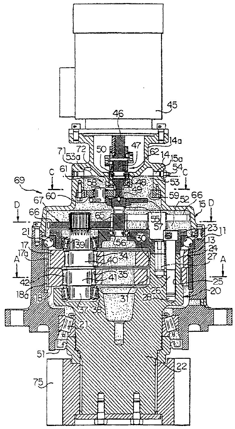
The axial positions of the two external driven gears (66) of each pair of gear sets (67) relative to the input shaft (62) are the same, offset along the axial direction of the input shaft (62) Different pairs of gear sets (67) are set. Therefore, only two external driven gears (66) constituting a pair of gear sets (67) are provided at the same axial position of the input shaft (62). Therefore, even if the diameters of the external driven gears (66) are made very large, the external driven gears (66) do not interfere with each other. Therefore, the reduction ratio can be easily increased by utilizing the external driving gear and the external driven gear.
Description
发明领域field of invention
本发明涉及一种偏心摆动型减速器,通过偏心旋转齿轮而实现减速。The invention relates to an eccentric oscillating type reducer, which realizes deceleration by eccentrically rotating gears.
背景技术Background technique
本申请人在日本提出的申请号为No.2000-202030的专利申请中介绍了一种偏心摆动型减速器,通过利用具有同样形状的小齿轮形成多个小齿轮,能够降低制造成本,并简化装配。In the patent application No. 2000-202030 filed by the applicant in Japan, an eccentric oscillating speed reducer is introduced. By using pinions with the same shape to form multiple pinions, the manufacturing cost can be reduced and simplified. assembly.
这种偏心摆动型减速器由下列元件组成:具有形成在内周边上的内齿的外壳体;多个被组装在所述外壳体内的小齿轮,所述小齿轮的外周边上具有能和所述内齿啮合的外齿,所述外齿的数量略少于内齿的数量,所述多个小齿轮平行于轴线方向并列设置;偶数个但不少于4个的曲柄轴,这些曲柄轴沿圆周方向上彼此等角度相隔分布,曲柄轴的中心部位被插在所述小齿轮内,从而随着曲柄轴的转动,所述小齿轮偏心转动;插入所述外壳体内用于转动地支撑曲柄轴两端的支架;被所述外壳体转动地支撑的输入轴,在该输入轴上具有和所述内齿同轴的外主动齿轮;分别安装在曲柄轴上的外从动齿轮,所述外从动齿轮和外主动齿轮啮合,同时环绕着所述外主动齿轮。This eccentric oscillating type speed reducer is composed of the following elements: an outer casing having internal teeth formed on the inner periphery; a plurality of pinion gears assembled in the outer The external teeth meshed with the internal teeth, the number of the external teeth is slightly less than the number of the internal teeth, and the plurality of pinions are arranged side by side parallel to the axial direction; an even number but not less than 4 crankshafts, these crankshafts Distributed at equiangular intervals from each other in the circumferential direction, the central portion of the crankshaft is inserted into the pinion so that the pinion rotates eccentrically as the crankshaft rotates; inserted into the housing for rotatably supporting the crank The brackets at both ends of the shaft; the input shaft rotatably supported by the outer shell, on which there is an external driving gear coaxial with the internal teeth; the external driven gears respectively installed on the crankshaft, the external The driven gear meshes with the external driving gear while surrounding the external driving gear.
然而,当曲柄轴的数量是偶数但不少于4个时,如果试图通过缩小外主动齿轮的直径同时增大每个外从动齿轮的直径而扩大偏心摆动型减速器的减速比,当每个外从动齿轮的直径还没有变得非常大时,相邻外从动齿轮已经彼此干涉了。因此,利用外主动齿轮和外从动齿轮进行减速,减速比不能非常大。例如当曲柄轴的数量是4个时,利用外主动齿轮和外从动齿轮进行减速,减速比最大是2.1。However, when the number of crankshafts is an even number but not less than 4, if an attempt is made to increase the reduction ratio of the eccentric oscillating type reducer by reducing the diameter of the external driving gear while increasing the diameter of each external driven gear, when each When the diameter of an external driven gear has not become very large, the adjacent external driven gears have interfered with each other. Therefore, using the external driving gear and the external driven gear for deceleration, the reduction ratio cannot be very large. For example, when the number of crankshafts is four, the reduction ratio is 2.1 at most by using the external driving gear and the external driven gear.
发明内容Contents of the invention
本发明的目的是提供一种偏心摆动型减速器,通过增加外主动齿轮和外从动齿轮的减速比,能够极大地增加最终减速比和最终输出力矩。The object of the present invention is to provide an eccentric oscillating type reducer, which can greatly increase the final reduction ratio and the final output torque by increasing the reduction ratio of the external driving gear and the external driven gear.
以上目的可以通过一种偏心摆动型减速器而实现。该偏心摆动型减速器包括一在内周表面上形成有内齿的外壳体;多个被容纳在所述外壳体内部的小齿轮,所述小齿轮的外周表面上具有和所述内齿相啮合的外齿,外齿的数量略微比内齿的数量少,所述小齿轮平行于轴向并列分布;不少于4个的偶数个曲柄轴,它们在圆周方向上彼此等角度地间隔分布,所述曲柄轴的中央部分插入所述小齿轮内,从而随着曲柄轴的转动,使小齿轮偏心地转动;被插入所述外壳体内用于转动地支撑所述曲柄轴两端的支架;被外壳体转动地支撑的一输入轴,它具有和内齿同轴的外主动齿轮;分别被安装在曲柄轴上的外从动齿轮,所述外从动齿轮在围绕外主动齿轮的同时和所述外主动齿轮啮合,所述偏心摆动型减速器的特征是:外从动齿轮被划分成多个齿轮对组,每组由两个在圆周方向上彼此间隔180°分布的外从动齿轮组成;构成每个齿轮对组的两个外从动齿轮相对于输入轴的轴向位置相同,不同齿轮对组在输入轴的轴向上彼此偏移。The above objects can be achieved by an eccentric swing type speed reducer. The eccentric oscillating speed reducer includes an outer casing with internal teeth formed on the inner peripheral surface; a plurality of pinion gears accommodated inside the outer peripheral surface; Meshing external teeth, the number of which is slightly less than the number of internal teeth, said pinions are arranged parallel to the axial direction; an even number of crankshafts not less than 4, which are equiangularly spaced from each other in the circumferential direction, The central portion of the crankshaft is inserted into the pinion so that the pinion rotates eccentrically as the crankshaft rotates; the brackets inserted into the housing for rotatably supporting both ends of the crankshaft; An input shaft rotatably supported by the body has an external driving gear coaxial with the internal teeth; external driven gears are respectively installed on the crankshaft, and the external driven gears are connected with the external driving gear while surrounding the external driving gear. The external driving gear meshes, and the feature of the eccentric swing type reducer is that the external driven gear is divided into a plurality of gear pair groups, and each group is composed of two external driven gears distributed at intervals of 180° from each other in the circumferential direction; The axial positions of the two external driven gears constituting each gear pair with respect to the input shaft are the same, and different gear pairs are offset from each other in the axial direction of the input shaft.
在本发明中,如上所述,外从动齿轮被划分成多个齿轮对组,每组由两个在圆周方向上彼此间隔180°分布的外从动齿轮组成;构成每个齿轮对组的两个外从动齿轮相对于输入轴的轴向位置相同,不同齿轮对组在输入轴的轴向上彼此偏移。因此,仅仅两个构成齿轮对组的外从动齿轮被设置在输入轴的相同的轴向位置上。因而,即使这些外从动齿轮的直径被制造的非常大,这些外从动齿轮也不会彼此干涉。因此,能够利用主动齿轮和从动齿轮,容易地增加减速比,因此能够在不降低偏心摆动型减速器的最终输出力矩的前提下扩大最终减速比。In the present invention, as described above, the external driven gear is divided into a plurality of gear pairs, and each group is composed of two external driven gears distributed at intervals of 180° from each other in the circumferential direction; The axial positions of the two external driven gears relative to the input shaft are the same, and the different gear pairs are offset from each other in the axial direction of the input shaft. Therefore, only the two outer driven gears forming the gear pair are arranged at the same axial position on the input shaft. Thus, even if the diameters of the external driven gears are made extremely large, the external driven gears do not interfere with each other. Therefore, the reduction ratio can be easily increased by using the driving gear and the driven gear, so the final reduction ratio can be enlarged without reducing the final output torque of the eccentric oscillating type speed reducer.
此外,按照本发明优选实施例的配置,由于每个加工孔的底部和每个螺栓顶部之间所形成的空间没有位于柱部分,而是位于底部部分,整个柱部分是实心结构,因此增加了强度并允许输出更大的力矩。Furthermore, according to the configuration of the preferred embodiment of the present invention, since the space formed between the bottom of each machined hole and the top of each bolt is located not at the column portion but at the bottom portion, the entire column portion is a solid structure, thereby increasing the strength and allow greater torque output.
此外,按照本发明优选实施例的配置,设置在外壳体和输入轴之间的轴承和油封可以被密封空间内的润滑油所润滑,从而没有必要制造用于润滑轴承和油封的润滑设备,或没有必要进行补充润滑油的操作。In addition, according to the configuration of the preferred embodiment of the present invention, the bearing and the oil seal provided between the outer case and the input shaft can be lubricated by lubricating oil in the sealed space, so that it is unnecessary to manufacture a lubricating device for lubricating the bearing and the oil seal, or No relubrication operation is necessary.
另外,按照本发明优选实施例的配置,即使密封空间内的润滑油由于减速器的温度升高而膨胀,这种膨胀也可以通过气室内空气的压缩而被吸收,从而可以避免润滑油的泄漏。In addition, according to the configuration of the preferred embodiment of the present invention, even if the lubricating oil in the sealed space expands due to the temperature rise of the speed reducer, this expansion can also be absorbed by the compression of the air in the air chamber, so that the leakage of lubricating oil can be avoided .
在此,日本专利申请No.2001-277509(2002年9月13日申请)所包含的全部主题被包含在本发明中。Here, all the subject matter contained in Japanese Patent Application No. 2001-277509 (filed on September 13, 2002) is included in the present invention.
附图简介Brief introduction to the drawings
图1是一个显示本发明实施例的横截面前视图;Fig. 1 is a cross-sectional front view showing an embodiment of the present invention;
图2是沿图1中A-A线箭头所示方向所作的横截面视图;Fig. 2 is a cross-sectional view made along the direction indicated by the A-A line arrow in Fig. 1;
图3是支架的柱部分以及其附近的横截面前视图;Figure 3 is a cross-sectional front view of the column portion of the stent and its vicinity;
图4是沿图3中B-B线箭头所示方向所作的横截面视图;Fig. 4 is a cross-sectional view made along the direction indicated by the B-B line arrow in Fig. 3;
图5是沿图1中C-C线箭头所示方向所作的横截面视图;Fig. 5 is a cross-sectional view made along the direction indicated by the C-C line arrow in Fig. 1;
图6是沿图1中D-D线箭头所示方向所作的横截面视图;Fig. 6 is a cross-sectional view made along the direction indicated by the D-D line arrow in Fig. 1;
图7是类似于图6的横截面视图,显示了本发明的另一个实施例。Figure 7 is a cross-sectional view similar to Figure 6 showing another embodiment of the present invention.
优选实施例介绍Introduction to preferred embodiments
下文结合附图介绍本发明的实施例。Embodiments of the present invention are described below in conjunction with the accompanying drawings.
在图1和2中,附图标记11代表一大致圆柱形的圆柱体,其中心轴线沿垂直方向延伸(竖立方向),该圆柱体11被固定在未示出的风能发电装置的固定外壳内。附图标记13代表多个内齿销,其被用作设置在圆柱体11中心部分内周表面上的内齿。这些内齿销13沿轴向延伸,并在圆周方向上彼此等角度间隔分布。In FIGS. 1 and 2,
一圆柱形阶梯上盖14被固定在圆柱体11的上端,上盖14的底部用于封闭圆柱体11的上端上的开口,用于支撑将在下文介绍的驱动电动机的大致圆柱形的延伸部分14a被形成在上盖14的上表面上。上述圆柱体11和上盖14作为整体形成一外壳体15,在其内周表面上形成有内齿(内齿销13),其下端是畅通的,上盖14形成外壳体15的上壁。A cylindrical stepped
附图标记17和18代表多个被容纳在外壳体15内的小齿轮,图中仅显示两个,这些小齿轮17、18沿轴向(垂直方向)彼此间隔分布。在小齿轮17和18的外周表面上具有外齿17a和18a,所述外齿的数量略少于内齿销13的的数量,在图中所示情况下少一个。这些相邻的小齿轮17和18与圆柱体11的内齿销13啮合,它们的相位相差180°。
附图标记20代表支架,其上端部分和中央部分被插在上述外壳体15内,其下端部分从外壳体15内向下突出。利用一对在垂直方向(轴向)上间隔分布的轴承21,外壳体15转动地支撑在所述支架20上。支架20具有底部22和盘形端板部分23,底部22(一侧)比小齿轮17和18更低,盘形端板部分23所在位置(另一侧)比小齿轮17和18更高。此外,支架20具有整体形成在底部22上的柱形部分24,每个柱形部分24具有大致三角形横截面并从上表面(另一侧表面)向端板部分23轴向延伸。这些柱形部分24的数量是不小于4的偶数,图中显示是4个,并在圆周方向上彼此等角度地间隔分布。
在图1~4中,附图标记25代表从每个柱部分24的上表面(另一侧表面)向下延伸的加工孔。每个加工孔25延伸穿透支架20的柱部分24,其下表面(下端)位于底部22内。多个插入端板部分23的螺栓26分别拧入如此形成在柱部分24和底部22上的加工孔25内。因此利用螺栓26将端板部分23和柱部分24紧固在一起,使得端板部分23被固定在柱部分24上。In FIGS. 1 to 4 ,
此外,这些螺栓26的末端(下端)以与加工孔25相同的方式,比柱部分24的近端(下端)更靠近底部22。因此,加工孔25的底部和螺栓26的末端之间所形成的空间28位于底部22内。顺便提及,附图标记27代表插在端板部分23和柱部分24内的定位销。Further, the ends (lower ends) of these
如果加工孔25的底部和螺栓26的末端之间所形成的空间28没有位于柱部分24内而是位于底部22内,整个柱部分24就是一个实心结构,因此增加了强度,并允许输出更大的力矩。在小齿轮17和18上分别形成有沿圆周方向上彼此间隔分布的松配合孔30和31,这些孔具有大致三角形横截面,并且数量等于柱部分24的数量(4个)。支架20的柱部分24分别沿轴向宽松地通过小齿轮17和18上的松配合孔30和31。此外,上述底部22、端板部分23、柱部分24和螺栓6作为整体构成支架20。If the
再次参考图1和2,沿圆周方向彼此等角度间隔分布的通孔34和35分别被形成在小齿轮17和18上,所述通孔34和35的数量等于柱部分24的数量,在图示情况下是4个。此外在圆周方向上,这些通孔34和35分布在相邻的通孔30和31之间的中点上。Referring again to FIGS. 1 and 2, through holes 34 and 35 distributed at equiangular intervals in the circumferential direction are formed on the
附图标记37代表曲柄轴,其数量是不小于4的偶数,在图示情况下,等于通孔34和35的数量(4个),这些曲柄轴37在圆周方向上彼此等角度地间隔分布。这些曲柄轴的下端(一端)和上端(另一端)分别被支架20的底部22和端板部分23通过轴承38和39而转动地支撑。每个曲柄轴37在其轴向中央部分具有两个偏心部分40和41,这两个偏心部分和曲柄轴37的中心轴之间的偏离距离相同,在圆周方向上,这两个偏心部分的相位相差180°。此外,这些偏心部分40和41分别插入小齿轮17和18的通孔34和35内,滚柱轴承42位于两者之间。
此外,当这些曲柄轴37围绕它们的中央轴线转动时,偏心部分40和41在通孔34和35内偏心转动,导致小齿轮17和18偏心地转动(旋转),小齿轮17和18的相位相差180°。此时,由于内齿销13的数量与外齿17a以及18a的数量略微不同(在图示情况下,外齿17a和18a的数量比内齿销13的数量少1个),通过小齿轮17和18的偏心转动,支架20低速转动。In addition, when these crank
在图1和图5中,附图标记45代表驱动电动机,电动机45被固定在外壳体15的延伸部分14a的上端,穿过上盖14中心的中间轴47与从驱动电动机45垂直延伸出来的输出轴46的下端相连。此外,轴承48位于中间轴47和上盖14之间,使得上壳体15转动地支撑该中间轴47。此外,由外齿轮构成的中心齿轮49被形成在中间轴47的下端。此外被用作密封元件的油封50和51分别被安置在中间轴47和外壳体15(上盖14)之间以及外壳体15(圆柱体11)的下端和支架20的底部22之间。因此在外壳体15内形成密封空间52,将润滑油53注入该密封空间52。应该指出是附图标记15a代表被形成在外壳体15上的润滑油53的入口,利用可拆卸的塞子54封闭入口15a。In Fig. 1 and Fig. 5, reference numeral 45 represents a drive motor, and the motor 45 is fixed on the upper end of the extension portion 14a of the
附图标记55代表被设置在中间轴47正下方的转动轴,这两个轴的轴线重合。支架20的端板部分23利用轴承56转动地支撑转动轴55的下端部分。附图标记57代表被连接在转动轴55上端的盘形连接件,多个在圆周方向上彼此间隔分布的销58被固定在连接元件57上。
附图标记59代表被固定在上盖14的内周表面上并与所述中心齿轮49相对的内齿轮,多个被销58转动地支撑的行星齿轮60和内齿轮59以及中心齿轮49啮合。从而,利用由具有中心齿轮49的中间轴47、连接元件57、销58、内齿轮59和行星齿轮60组成的行星减速机构61,对输出轴46的转动进行减速,然后将转动传送到转动轴55。上述中间轴47和转动轴55作为一个整体构成输入轴62,被用作前一级减速齿轮的上述行星减速机构61被设置在输入轴62的中间部分。
在图1、2和6中,在输入轴62具体地说是转动轴55的下端具有外主动齿轮65,多个(4个)在围绕外主动齿轮65的同时与外主动齿轮65啮合的外从动齿轮66被安装到各自曲柄轴37的上端部分,如图所示,这些外从动齿轮66沿圆周方向上彼此以90°角等间隔分布。In Fig. 1, 2 and 6, there is an
外从动齿轮66被划分成多对(2)齿轮组(对)67,每对齿轮组67包括两个在圆周方向上彼此间隔180°分布的外从动齿轮66。此外,构成每对齿轮组67的两个外从动齿轮66相对于输入轴62的轴向位置相同,换句话说,这两个外从动齿轮66在相同的轴向位置与外主动齿轮65啮合。另一方面,不同对的齿轮组67在输入轴62的轴向上间隔分布(属于不同对齿轮组67的外从动齿轮66在轴向间隔分布的位置与外主动齿轮65啮合)。此外,这两对齿轮组67的外从动齿轮66沿圆周方向上彼此以90°角间隔分布。The external driven
上述外壳体15、小齿轮17和18、支架20、曲柄轴37、输入轴62、外主动齿轮65和外从动齿轮66作为一个整体构成偏心摆动型减速器69。这个偏心摆动型减速器69垂直地分布,从而输入轴62位于上侧。The above-mentioned
利用上述润滑油53对偏心摆动型减速器69的内部元件也就是小齿轮17和18、轴承21、曲柄轴37等进行润滑。然而在这个实施例中,将如下文所解释的那样,轴承48和油封50也被润滑油53润滑,从而没有必要制造用于润滑轴承48和油封50的润滑设备,或没有必要进行补充润滑油的操作。The internal components of the eccentric oscillating
换句话说,所提供的配置是这样的,即外壳体15的上壁(上盖14)的一部分被制造得向上突出,输入轴62穿过所述上壁,因此,突出部分71(密封空间52的上端部分)位于被设置在输入轴62和上盖14之间的轴承48和油封50的上方,注入密封空间52内的润滑油53的液面53a升高到该突出部分71,也就是位于轴承48和油封50的上方,因此轴承48和油封50被润滑。In other words, the configuration provided is such that a part of the upper wall (upper cover 14) of the
此外,在这个实施例中,将空气注入外壳体15上壁(突出部分71)和润滑油53的液面53a之间,以形成气室72。从而即使长期连续操纵偏心摆动型减速器69,偏心摆动型减速器69的温度升高,导致密封空间52内的润滑油53液面膨胀,但是通过使气室72内的空气被压缩,这种膨胀也能被吸收。因而,能够阻止润滑油53从偏心摆动型减速器69内泄漏。Furthermore, in this embodiment, air is injected between the upper wall (protrusion 71 ) of the
附图标记75代表被固定在支架20上具体地说被固定在从外壳体15的下端向下突出的底部22上的传动齿轮。该传动齿轮75与被固定在风能发电装置的枢轴上的外齿轮啮合。此外,通过上述行星减速齿轮机构61和偏心摆动型减速器69的减速作用,驱动电动机45的转动被传送给上述枢轴,从而允许具有枢轴和叶片的发电机在水平平面内根据风向转动,因此提高了发电效率。Reference numeral 75 denotes a transmission gear fixed to the
下文将介绍本发明实施例的操作。The operation of the embodiment of the present invention will be described below.
假设风向已经改变,风速仪已经转动,对应于该转动的控制信号已经从控制装置被输出给驱动电动机45。此时虽然驱动电动机45的输出轴46根据控制信号转动,该输出轴46的转动首先被行星减速齿轮机构61减速,然后才传输到转动轴55,以便使转动轴55旋转。Assuming that the wind direction has changed, the anemometer has rotated, and a control signal corresponding to this rotation has been output from the control device to the drive motor 45 . Although the output shaft 46 of the driving motor 45 rotates according to the control signal at this time, the rotation of the output shaft 46 is first decelerated by the planetary
随后,转动轴55的转动在被外主动齿轮65和外从动齿轮66减速后才传输到曲柄轴37,并且被传送到曲柄轴37上的转动驱动力导致小齿轮17和18在外壳体15内如上所述那样偏心转动。从而输入轴62的转动速度被极大地降低,并通过传动齿轮75传送给风能发电装置的枢轴,从而使发电机在水平面内旋转,使得发电效率最高。Subsequently, the rotation of the
如上所述,外从动齿轮66被划分成多个齿轮组67,每个齿轮组67包括两个在圆周方向上以180°角间隔分布的外从动齿轮,构成每个齿轮组67的两个外从动齿轮66相对于输入轴62在轴向位置上是相同的,同时不同的齿轮组67在输入轴62的轴向方向彼此偏移分布。从而仅仅构成一对齿轮组67的两个外从动齿轮66被设置在输入轴62的相同的轴向位置上。因而,即使这些外从动齿轮66的直径被制造的非常大,这些外从动齿轮66也不会彼此干涉。因此,能够利用外主动齿轮65和外从动齿轮66,容易地扩大减速比,因此能够在不降低偏心摆动型减速器69的最终输出力矩的前提下极大地扩大减速比。例如在这个实施例内,当曲柄轴37的数量是4时,利用外主动齿轮65和外从动齿轮66,减速比可以被增加到5.3。As mentioned above, the external driven
应该指出的是,虽然在上述实施例中,总共设置构成两个齿轮组67的4个外从动齿轮66,然而在本发明中,也可以如图7所示设置构成三个齿轮组67的6个外从动齿轮66。在此情况下,齿轮组67在圆周方向上彼此间隔60°分布,同时在输入轴62的轴向方向上位于三个不同的位置。It should be noted that, although in the above-mentioned embodiment, a total of four external driven
此外,虽然在上述实施例中,外壳体15被设计成固定的,而支架20是旋转的,从而从支架20输出低速转动,在本发明中,支架可以被设计成固定的,而外壳体15是转动的,从而从转动一侧即外壳体15输出低速转动。In addition, although in the above-mentioned embodiment, the
如上所述,根据本发明,能够利用外主动齿轮和外从动齿轮,极大地扩大最终减速比和最终输出力矩。As described above, according to the present invention, the final reduction ratio and the final output torque can be greatly enlarged by using the external driving gear and the external driven gear.
附图标记说明Explanation of reference signs
(图1)(figure 1)
13:内齿13: Internal teeth
15:外壳体15: Outer shell
17、18:小齿轮17, 18: pinion gear
17a、18a:外齿17a, 18a: External teeth
20:支架20: Bracket
21:轴承21: Bearing
22:底部22: Bottom
23:端板部分23: End plate part
37:曲柄轴37: crankshaft
48:轴承48: Bearing
50:油封50: oil seal
51:油封51: oil seal
52:密封空间52: Sealed Space
53:润滑油53: lubricating oil
53a:液面53a: liquid level
62:输出轴62: output shaft
72:气室72: air chamber
(图3)(image 3)
24:柱部分24: column part
25:加工孔25: Machining holes
26:螺栓26: Bolt
28:空间28: space
(图6)(Figure 6)
65:外主动齿轮65: External driving gear
66:外从动齿轮66: External driven gear
67:齿轮组67: gear set
Claims (5)
Applications Claiming Priority (2)
| Application Number | Priority Date | Filing Date | Title |
|---|---|---|---|
| JP2001277509A JP4004256B2 (en) | 2001-09-13 | 2001-09-13 | Eccentric rocking speed reducer |
| JP277509/2001 | 2001-09-13 |
Publications (2)
| Publication Number | Publication Date |
|---|---|
| CN1409029A CN1409029A (en) | 2003-04-09 |
| CN1237292C true CN1237292C (en) | 2006-01-18 |
Family
ID=19102024
Family Applications (1)
| Application Number | Title | Priority Date | Filing Date |
|---|---|---|---|
| CNB021431345A Expired - Lifetime CN1237292C (en) | 2001-09-13 | 2002-09-13 | Eccentrically swing type speed reducer |
Country Status (7)
| Country | Link |
|---|---|
| US (1) | US6679801B2 (en) |
| EP (1) | EP1296084B1 (en) |
| JP (1) | JP4004256B2 (en) |
| CN (1) | CN1237292C (en) |
| DE (1) | DE60233373D1 (en) |
| DK (1) | DK1296084T3 (en) |
| ES (1) | ES2329766T3 (en) |
Cited By (2)
| Publication number | Priority date | Publication date | Assignee | Title |
|---|---|---|---|---|
| CN102192275A (en) * | 2010-02-03 | 2011-09-21 | 住友重机械工业株式会社 | Eccentric oscillating reducer and method for manufacturing eccentric body shaft thereof |
| CN101606005B (en) * | 2007-02-05 | 2013-05-01 | 住友重机械工业株式会社 | Power transmission device and manufacturing method thereof |
Families Citing this family (50)
| Publication number | Priority date | Publication date | Assignee | Title |
|---|---|---|---|---|
| AU2002368081A1 (en) * | 2002-07-02 | 2004-01-23 | Vishvas Ambardekar | Eccentric gearbox |
| US7081062B2 (en) * | 2002-11-25 | 2006-07-25 | Delbert Tesar | Standardized rotary actuator |
| US9879760B2 (en) | 2002-11-25 | 2018-01-30 | Delbert Tesar | Rotary actuator with shortest force path configuration |
| JP4312484B2 (en) * | 2003-03-26 | 2009-08-12 | 住友重機械工業株式会社 | Swing intermeshing planetary gear unit |
| CN102705162B (en) * | 2003-08-12 | 2014-10-22 | 纳博特斯克株式会社 | Yaw drive device for wind power generator |
| JP2006038108A (en) * | 2004-07-27 | 2006-02-09 | Sumitomo Heavy Ind Ltd | Inscribed engagement planetary reduction gear mechanism and inscribed engagement planetary reduction gear device |
| CN100351792C (en) * | 2004-08-23 | 2007-11-28 | 中兴通讯股份有限公司 | A real-time task management and scheduling method |
| JP4901156B2 (en) * | 2005-08-11 | 2012-03-21 | ナブテスコ株式会社 | Reduction gear |
| JP4762643B2 (en) * | 2005-08-22 | 2011-08-31 | ナブテスコ株式会社 | Center crank type eccentric oscillating speed reducer |
| JP4749814B2 (en) * | 2005-09-26 | 2011-08-17 | ナブテスコ株式会社 | Differential oscillating speed reducer |
| EP1988307B1 (en) | 2005-09-26 | 2011-11-09 | Nabtesco Corporation | Speed reducer |
| JP4909578B2 (en) * | 2005-12-08 | 2012-04-04 | ナブテスコ株式会社 | Windmill drive |
| KR101233896B1 (en) * | 2006-01-13 | 2013-02-15 | 나부테스코 가부시키가이샤 | Eccentric rocking type reduction gear |
| US8323140B2 (en) * | 2006-06-13 | 2012-12-04 | Nabtesco Corporation | Reduction gear transmission |
| JP4820713B2 (en) * | 2006-08-10 | 2011-11-24 | 住友重機械工業株式会社 | Decelerator |
| JP5069892B2 (en) * | 2006-10-04 | 2012-11-07 | ナブテスコ株式会社 | Differential oscillating speed reducer |
| JP4747128B2 (en) * | 2007-04-24 | 2011-08-17 | 住友重機械工業株式会社 | Eccentric oscillation reduction device |
| JP5088970B2 (en) | 2008-02-13 | 2012-12-05 | ナブテスコ株式会社 | Eccentric reducer |
| WO2009110023A1 (en) | 2008-03-03 | 2009-09-11 | ナブテスコ株式会社 | Eccentric speed reducer |
| JP2009008095A (en) * | 2008-09-09 | 2009-01-15 | Nabtesco Corp | Wind turbine blade pitch angle control device |
| JP2008298295A (en) * | 2008-09-11 | 2008-12-11 | Nabtesco Corp | Differential oscillating speed reducer |
| JPWO2010038380A1 (en) * | 2008-10-03 | 2012-02-23 | ナブテスコ株式会社 | Pitch drive device for windmill |
| JP5074437B2 (en) * | 2009-03-16 | 2012-11-14 | 住友重機械工業株式会社 | Reducer for yaw drive of wind power generator |
| JP5270462B2 (en) * | 2009-06-15 | 2013-08-21 | ナブテスコ株式会社 | Eccentric oscillating gear device and crankshaft assembling method in eccentric oscillating gear device |
| JP5543832B2 (en) * | 2010-04-16 | 2014-07-09 | ナブテスコ株式会社 | Windmill drive |
| JP5425700B2 (en) * | 2010-04-30 | 2014-02-26 | 住友重機械工業株式会社 | Reduction device for wind power generation equipment and installation method thereof |
| ES2564994T3 (en) * | 2010-07-08 | 2016-03-30 | Nabtesco Corporation | Deceleration device |
| DE102011015858B3 (en) * | 2011-04-01 | 2012-08-02 | Repower Systems Ag | Method and device for quick oil change to drive equipment of wind turbines |
| JP5654971B2 (en) * | 2011-09-16 | 2015-01-14 | 住友重機械工業株式会社 | Eccentric oscillation type speed reducer |
| JP5988424B2 (en) * | 2012-07-03 | 2016-09-07 | ナブテスコ株式会社 | Eccentric oscillating gear unit |
| JP5910378B2 (en) | 2012-07-11 | 2016-04-27 | 株式会社ジェイテクト | Deceleration mechanism and motor rotational force transmission device having the same |
| JP6154739B2 (en) * | 2013-12-12 | 2017-06-28 | 住友重機械工業株式会社 | Reduction gear |
| KR101559476B1 (en) * | 2014-03-18 | 2015-10-13 | (주) 파루 | Worm gear apparatus |
| JP6342206B2 (en) * | 2014-04-18 | 2018-06-13 | ナブテスコ株式会社 | Eccentric reducer |
| JP6522400B2 (en) * | 2015-04-15 | 2019-05-29 | ナブテスコ株式会社 | Reduction gear and gear used therefor |
| JP2016205603A (en) * | 2015-04-28 | 2016-12-08 | 株式会社ハーモニック・ドライブ・システムズ | Planetary gear reduction gear |
| ITUB20152131A1 (en) * | 2015-07-13 | 2017-01-13 | Fondazione St Italiano Tecnologia | ROTATIONAL SPEED REDUCER |
| CN105023503A (en) * | 2015-08-03 | 2015-11-04 | 南京康尼机电股份有限公司 | High precision economic cycloidal pin-wheel reducer for teaching |
| DE102015014087B4 (en) * | 2015-11-03 | 2017-11-09 | Sew-Eurodrive Gmbh & Co Kg | transmission |
| JP6681201B2 (en) * | 2016-01-22 | 2020-04-15 | ナブテスコ株式会社 | Steering device |
| JP6789689B2 (en) * | 2016-02-04 | 2020-11-25 | 日本電産シンポ株式会社 | Decelerator |
| JP6257683B2 (en) * | 2016-04-04 | 2018-01-10 | 住友重機械工業株式会社 | Deceleration device having an eccentric oscillation type deceleration mechanism |
| JP6836336B2 (en) * | 2016-05-20 | 2021-02-24 | ナブテスコ株式会社 | Gear device |
| JP6752070B2 (en) * | 2016-07-12 | 2020-09-09 | ナブテスコ株式会社 | Gear device |
| KR101907397B1 (en) * | 2017-04-26 | 2018-10-12 | 주식회사 세진아이지비 | Servo cylinder |
| JP7058954B2 (en) * | 2017-07-24 | 2022-04-25 | 株式会社マキタ | Processing machine |
| CN109058389A (en) * | 2018-09-19 | 2018-12-21 | 杭州星河传动机械研究院有限公司 | Planetary balance-wheel speed reducer |
| CN112112940B (en) * | 2019-06-21 | 2022-03-29 | 宁波瀚晟传动技术有限公司 | Transmission mechanism |
| CN113108045A (en) * | 2021-04-15 | 2021-07-13 | 安徽理工大学 | Three-ring six-plate gear reducer |
| JP2025119912A (en) * | 2024-02-02 | 2025-08-15 | ナブテスコ株式会社 | Reducers and industrial machinery |
Family Cites Families (10)
| Publication number | Priority date | Publication date | Assignee | Title |
|---|---|---|---|---|
| US3129611A (en) * | 1960-10-14 | 1964-04-21 | Lee Engineering Company | Speed reducers |
| US3994187A (en) * | 1975-02-14 | 1976-11-30 | The United States Of America As Represented By The Secretary Of The Navy | Epicyclic transmission |
| US4239977A (en) * | 1978-09-27 | 1980-12-16 | Lisa Strutman | Surge-accepting accumulator transmission for windmills and the like |
| US4683985A (en) * | 1985-01-04 | 1987-08-04 | Dresser Industries, Inc. | Lubrication system for a vertical gear unit |
| DE3878023T2 (en) * | 1987-05-14 | 1993-06-09 | Sumitomo Heavy Industries | PLANETARY TRANSMISSION SYSTEM. |
| JPH02261943A (en) * | 1989-03-30 | 1990-10-24 | Teijin Seiki Co Ltd | planetary gear reducer |
| SK405092A3 (en) * | 1992-12-31 | 1995-09-13 | Jozef Herstek | Multisatelit gear box |
| US5908372A (en) * | 1994-02-14 | 1999-06-01 | Spinea S.R.O. | Gear system |
| JP4020560B2 (en) * | 2000-02-07 | 2007-12-12 | ナブテスコ株式会社 | Eccentric rocking speed reducer |
| JP3850203B2 (en) | 2000-07-04 | 2006-11-29 | ナブテスコ株式会社 | Eccentric rocking speed reducer |
-
2001
- 2001-09-13 JP JP2001277509A patent/JP4004256B2/en not_active Expired - Fee Related
-
2002
- 2002-09-10 US US10/241,053 patent/US6679801B2/en not_active Expired - Lifetime
- 2002-09-13 EP EP02020675A patent/EP1296084B1/en not_active Expired - Lifetime
- 2002-09-13 ES ES02020675T patent/ES2329766T3/en not_active Expired - Lifetime
- 2002-09-13 DE DE60233373T patent/DE60233373D1/en not_active Expired - Lifetime
- 2002-09-13 DK DK02020675T patent/DK1296084T3/en active
- 2002-09-13 CN CNB021431345A patent/CN1237292C/en not_active Expired - Lifetime
Cited By (2)
| Publication number | Priority date | Publication date | Assignee | Title |
|---|---|---|---|---|
| CN101606005B (en) * | 2007-02-05 | 2013-05-01 | 住友重机械工业株式会社 | Power transmission device and manufacturing method thereof |
| CN102192275A (en) * | 2010-02-03 | 2011-09-21 | 住友重机械工业株式会社 | Eccentric oscillating reducer and method for manufacturing eccentric body shaft thereof |
Also Published As
| Publication number | Publication date |
|---|---|
| JP4004256B2 (en) | 2007-11-07 |
| ES2329766T3 (en) | 2009-12-01 |
| EP1296084A2 (en) | 2003-03-26 |
| US6679801B2 (en) | 2004-01-20 |
| EP1296084B1 (en) | 2009-08-19 |
| DK1296084T3 (en) | 2009-12-14 |
| EP1296084A3 (en) | 2007-08-01 |
| JP2003083400A (en) | 2003-03-19 |
| US20030054912A1 (en) | 2003-03-20 |
| DE60233373D1 (en) | 2009-10-01 |
| CN1409029A (en) | 2003-04-09 |
Similar Documents
| Publication | Publication Date | Title |
|---|---|---|
| CN1237292C (en) | Eccentrically swing type speed reducer | |
| CN1902415A (en) | Eccentrically swinging gear device | |
| CN102066719B (en) | A reciprocating piston mechanism | |
| CN1576644A (en) | Internal tooth gear mechanism and planet gear speed reducer | |
| CN1333439A (en) | Planetary speed variator | |
| CN1447043A (en) | Reducer and reducer series | |
| CN1290986A (en) | Gear drive motor and gear drive motor series | |
| CN1514915A (en) | Rotary transmission device and hydraulic drive device | |
| CN1576645A (en) | Speed reducer | |
| CN1262772C (en) | A star gear reducer adopting a star gear transmission assembly | |
| CN110701251A (en) | Multistage coaxial surface contact oscillating tooth precision speed reducer | |
| CN1376237A (en) | device for converting linear reciprocating motion into rotational motion | |
| CN1043678C (en) | Differential type internally meshing planetary gear structure | |
| CN1522931A (en) | Power plant for automatic two- and three-wheel vehicles | |
| CN109780163B (en) | Reciprocating type cylindrical sine end face oscillating tooth speed reducer | |
| JP2007232220A5 (en) | ||
| CN101046239A (en) | reducer | |
| CN1072339C (en) | Combined gear teeth mechanism | |
| JP2007198611A5 (en) | ||
| CN1654819A (en) | Gearbox for wind turbine | |
| CN1209188A (en) | Assembly for direct connecting of internal combustion engine and machine driven | |
| CN1074515C (en) | Optional tooth number complex conjugate tooth pin-wheel gearing device | |
| CN2367777Y (en) | Counter-rotating double belt unit | |
| CN2299188Y (en) | Combined gear teeth mechanism | |
| CN2823673Y (en) | Gear speed reducing mechanism and rim motor with same |
Legal Events
| Date | Code | Title | Description |
|---|---|---|---|
| C06 | Publication | ||
| PB01 | Publication | ||
| C10 | Entry into substantive examination | ||
| SE01 | Entry into force of request for substantive examination | ||
| C14 | Grant of patent or utility model | ||
| GR01 | Patent grant | ||
| CX01 | Expiry of patent term |
Granted publication date: 20060118 |
|
| CX01 | Expiry of patent term |