CN1237294C - Devices for controlling the flow medium - Google Patents
Devices for controlling the flow medium Download PDFInfo
- Publication number
- CN1237294C CN1237294C CNB008063702A CN00806370A CN1237294C CN 1237294 C CN1237294 C CN 1237294C CN B008063702 A CNB008063702 A CN B008063702A CN 00806370 A CN00806370 A CN 00806370A CN 1237294 C CN1237294 C CN 1237294C
- Authority
- CN
- China
- Prior art keywords
- cone
- axis
- gate valve
- valve disc
- valve
- Prior art date
- Legal status (The legal status is an assumption and is not a legal conclusion. Google has not performed a legal analysis and makes no representation as to the accuracy of the status listed.)
- Expired - Fee Related
Links
Images


Classifications
-
- F—MECHANICAL ENGINEERING; LIGHTING; HEATING; WEAPONS; BLASTING
- F16—ENGINEERING ELEMENTS AND UNITS; GENERAL MEASURES FOR PRODUCING AND MAINTAINING EFFECTIVE FUNCTIONING OF MACHINES OR INSTALLATIONS; THERMAL INSULATION IN GENERAL
- F16K—VALVES; TAPS; COCKS; ACTUATING-FLOATS; DEVICES FOR VENTING OR AERATING
- F16K1/00—Lift valves or globe valves, i.e. cut-off apparatus with closure members having at least a component of their opening and closing motion perpendicular to the closing faces
- F16K1/16—Lift valves or globe valves, i.e. cut-off apparatus with closure members having at least a component of their opening and closing motion perpendicular to the closing faces with pivoted closure-members
- F16K1/18—Lift valves or globe valves, i.e. cut-off apparatus with closure members having at least a component of their opening and closing motion perpendicular to the closing faces with pivoted closure-members with pivoted discs or flaps
- F16K1/22—Lift valves or globe valves, i.e. cut-off apparatus with closure members having at least a component of their opening and closing motion perpendicular to the closing faces with pivoted closure-members with pivoted discs or flaps with axis of rotation crossing the valve member, e.g. butterfly valves
- F16K1/222—Shaping of the valve member
-
- F—MECHANICAL ENGINEERING; LIGHTING; HEATING; WEAPONS; BLASTING
- F16—ENGINEERING ELEMENTS AND UNITS; GENERAL MEASURES FOR PRODUCING AND MAINTAINING EFFECTIVE FUNCTIONING OF MACHINES OR INSTALLATIONS; THERMAL INSULATION IN GENERAL
- F16L—PIPES; JOINTS OR FITTINGS FOR PIPES; SUPPORTS FOR PIPES, CABLES OR PROTECTIVE TUBING; MEANS FOR THERMAL INSULATION IN GENERAL
- F16L55/00—Devices or appurtenances for use in, or in connection with, pipes or pipe systems
- F16L55/10—Means for stopping flow in pipes or hoses
Landscapes
- General Engineering & Computer Science (AREA)
- Engineering & Computer Science (AREA)
- Mechanical Engineering (AREA)
- Lift Valve (AREA)
- Signal Processing For Digital Recording And Reproducing (AREA)
- Feeding And Guiding Record Carriers (AREA)
- Sliding Valves (AREA)
- Output Control And Ontrol Of Special Type Engine (AREA)
- Water Treatment By Sorption (AREA)
- Infusion, Injection, And Reservoir Apparatuses (AREA)
- Check Valves (AREA)
- Threshing Machine Elements (AREA)
- Electrical Discharge Machining, Electrochemical Machining, And Combined Machining (AREA)
- Air Supply (AREA)
- Two-Way Televisions, Distribution Of Moving Picture Or The Like (AREA)
- Reverberation, Karaoke And Other Acoustics (AREA)
- Gas Separation By Absorption (AREA)
Abstract
Description
所属领域Field
本发明涉及一种用于压力室,特别是容器或者管道的截止闸阀,包括一个可相对位于壳体内的转动轴线摆动的阀盘,该阀盘在密封位置上,在密封装置的范围内从两个相反的流动方向上将通过所述壳体的流体截止,所述阀盘是偏心的,即具有一个设置在密封装置中心线以外的转动轴线,且该转动轴线特别是通过截止闸阀的主轴线延伸。The invention relates to a shut-off gate valve for a pressure chamber, especially a container or a pipeline, comprising a valve disc that can swing relative to a rotation axis located in the housing, the valve disc being in the sealing position, within the scope of the sealing device, from two The fluid through the housing is blocked in two opposite flow directions, the valve disc is eccentric, that is, has an axis of rotation arranged outside the center line of the sealing device, and the axis of rotation passes in particular through the main axis of the shut-off gate valve extend.
背景技术Background technique
在输送流动介质的管道内,流体是通过阀门、滑阀或者闸阀截止的。闸阀由于其结构长度明显短小,所以被优选采用。In the pipeline conveying the flowing medium, the fluid is shut off by valves, slide valves or gate valves. Gate valves are preferred due to their significantly shorter overall length.
闸阀的最简单的结构是,具有一个沿阀盘中线布置的转动轴。公知的结构形式也有偏心式的,其中的转动轴与阀盘隔开一定距离。这种结构通常可改善阀盘的密封功能,因为阀盘的密封装置不会被伸出壳体内部的转动轴所中断。所述转动轴通常位于阀盘的前面或后面。此外转动轴线或转动轴还可位于阀盘前面的中央,并且与截止闸阀的主轴相交,因而通常也和管道的主轴线相交。The simplest structure of a gate valve is to have a rotating shaft arranged along the centerline of the valve disc. Known constructions are also eccentric, in which the axis of rotation is at a distance from the valve disc. This configuration generally improves the sealing function of the valve disk, since the sealing of the valve disk is not interrupted by the rotating shaft protruding inside the housing. The axis of rotation is usually located either in front or behind the valve disc. Furthermore, the axis of rotation or axis of rotation can also be located centrally in front of the valve disk and intersect the main axis of the globe valve and thus usually also the main axis of the pipe.
此外还有所谓双偏心闸阀。除了所述的偏心,转动轴线或转动轴在该类型中还设置在主轴线之外,也就是说,距主轴线有一个很小的距离。该结构可实现自动关闭效果,或者在一个流动方向上实现强制关闭。在另一个流动方向上则会产生一个不利的持续开启压力,所以也必须得有一个持续的且很高的闭合力,该闭合力具有相应的很高的驱动力矩。长此下去特别是在管道压力较高的情况下,会产生泄漏点,从而使得管道中的截止侧无法实现无危险的操作。In addition, there are so-called double eccentric gate valves. In addition to the aforementioned eccentricity, the axis of rotation or axis of rotation is also arranged in this type outside the main axis, that is to say at a small distance from the main axis. The structure allows for an automatic shut-off effect, or a forced shut-off in one flow direction. In the other direction of flow, an unfavorable continuous opening pressure results, so that a continuous and high closing force with a correspondingly high driving torque is also necessary. In the long run, especially in the case of high pipeline pressures, leak points can be created, so that the shut-off side in the pipeline cannot be operated without danger.
发明概述Summary of the invention
从以上背景出发,本发明的任务是,提供一种具有改进密封效果的截止闸阀。另一个任务是,用更小的驱动力矩就行。Proceeding from the above background, the object of the present invention is to provide a gate shut-off valve with improved sealing effect. Another task is to use less drive torque.
为此,本发明提供一种用于压力室,特别是容器或者管道的截止闸阀,包括一个可相对位于壳体内的转动轴线摆动的阀盘,该阀盘可在密封位置上,在密封装置的范围内从两个相反的流动方向上将通过所述壳体的流体截止,所述阀盘是偏心的,即具有一个没置在密封装置中心线以外的转动轴线,且该转动轴线特别是通过截止闸阀的主轴线延伸,其特征是,所述密封装置的环绕密封面DF的位置如下:a.所述密封面DF为一个锥面部段,其母线确定出密封面DF相对于截止闸阀主轴线的夹角,b.所述母线在锥顶处相交,其位置按以下方式确定:b1.密封装置中心线与主轴线垂直相交,b2.转动轴线(转动点46)相对密封装置中心线隔开一个距离(偏心)布置,特别是位于主轴线上,并且垂直于密封装置中心线和主轴线延伸,b3.以转动轴线(转动点46)作为圆心确定一个密封圆,其直径小于管道的公称宽度DN,或者小于位于截止闸阀内部的有效内径,b4.所述密封圆与密封装置中心线的交点被标为A和C,密封圆与通过A和转动点的直线的交点被标为B,其中B位于越过中心线的点A的对面,b5.所述密封圆在点A的切线与直线B-C的交点被标为S0,b6.线段A-B沿切线推移,直到A与S0重合;推移后的B则表示锥顶S1,或者线段A-S0沿线段A-B推移,直到A与B重合;推移后的S0则表示锥顶S1。To this end, the present invention provides a shut-off gate valve for pressure chambers, especially containers or pipelines, comprising a valve disc that can swing relative to a rotation axis located in the housing, the valve disc can be in the sealing position, and the valve disc can be in the sealing position. The fluid passing through the housing is cut off from two opposite flow directions within the range, the valve disc is eccentric, that is, has an axis of rotation that is not placed outside the center line of the sealing device, and the axis of rotation is in particular passed through The main axis of the cut-off gate valve extends, and it is characterized in that the position of the surrounding sealing surface DF of the sealing device is as follows: a. The sealing surface DF is a cone section, and its generatrix determines that the sealing surface DF is relative to the main axis of the stop gate valve b. The busbars intersect at the top of the cone, and its position is determined in the following manner: b1. The centerline of the sealing device intersects the main axis perpendicularly; b2. The axis of rotation (rotation point 46) is separated from the centerline of the sealing device A distance (eccentric) arrangement, in particular on the main axis, and extending perpendicular to the center line of the sealing device and the main axis, b3. With the axis of rotation (rotation point 46) as the center, a sealing circle is defined whose diameter is smaller than the nominal width of the pipe DN, or less than the effective inner diameter inside the globe gate valve, b4. The intersections of the sealing circle and the centerline of the sealing device are marked as A and C, and the intersection of the sealing circle and the straight line passing through A and the turning point is marked as B, where B is located on the opposite side of the point A that crosses the center line, b5. The intersection of the tangent of the sealing circle at point A and the straight line B-C is marked as S0, b6. The line segment A-B is moved along the tangent until A coincides with S0; B after the shift Then it represents the cone top S1, or the line segment A-S0 moves along the line segment A-B until A and B coincide; the shifted S0 represents the cone top S1.
本发明的一种改进使得阀盘在两个流动方向上自动关闭。也就是说,关闭运动的最后一段通过作用在阀盘上的合成工作压力得到促进,而且与流动方向无关。在最简单的情况中,该效果可通过一个中央设置的阀盘实现,它在闭合位置上,在两个流动方向上,转动轴线两侧的面积大小不同,其中较大的面积相对于转动轴线按对角线布置,较小的面积也是如此。这种看起来不可能实现的装置,可通过阀盘的特定厚度以及在侧面范围内,离转动轴线距离最大,倾斜的环绕密封面得到。密封装置的侧面具有一个沿主轴线方向和沿直径方向的空间深度。恰恰是沿直径方向的深度可实现两个流动方向上的不同面积关系。面对一个流动方向的阀盘一侧,通过转动轴被分成左表面和右表面。为产生闭合力,该表面必须有差别。对于一个从流动方向上观察的阀盘,它向右转动关闭时,如果左表面大于右表面就可产生一个强制关闭效果。同样的条件也适用于另一个流动方向上阀盘的另一侧。还可以通过密封面侧面倾斜的方式,使得所述位于一侧的左阀盘表面大于位于另一侧的右阀盘表面(即对面的表面)。A refinement of the invention enables the valve disc to automatically close in both flow directions. That is, the final stage of the closing movement is facilitated by the resultant operating pressure on the valve disc, independent of the flow direction. In the simplest case, this effect can be achieved by a centrally arranged valve disc, which in the closed position has different sizes on either side of the axis of rotation in both flow directions, with the larger area relative to the axis of rotation Arranged diagonally, the same goes for smaller areas. This seemingly impossible arrangement is achieved by a specific thickness of the valve disk and, in the lateral region, an inclined surrounding sealing surface at a maximum distance from the axis of rotation. The sides of the seal have a spatial depth in the direction of the main axis and in the direction of the diameter. It is precisely the depth in the diametrical direction that enables different area relationships in the two flow directions. The side of the valve disc facing one flow direction is divided into a left surface and a right surface by the axis of rotation. To generate closure force, the surfaces must be differential. For a valve disc viewed from the flow direction, when it turns to the right to close, if the left surface is larger than the right surface, a forced closing effect can be produced. The same conditions apply to the other side of the disc in the other flow direction. The side surface of the sealing surface can also be inclined so that the surface of the left valve disc on one side is larger than the surface of the right valve disc on the other side (ie, the opposite surface).
优选采用环状密封件,特别是设置在阀盘圆周上的密封件,它在阀盘闭合时可压紧在环绕的密封面上。其中可产生一个环形应力,使压力均匀分布在圆周上,从而产生良好的环形密封效果。Preferably, an annular seal is used, in particular a seal arranged on the circumference of the valve disk, which can be pressed against the surrounding sealing surface when the valve disk is closed. A ring stress can be generated in it, so that the pressure is evenly distributed on the circumference, so as to produce a good ring seal effect.
所述密封面的倾斜可以不同程度地在侧面相对的边缘上,或者整体环绕地形成,以得到一种所谓的阀座锥或锥形。所述阀盘也可采用偏心结构,即其转动轴线位于阀盘或所属密封装置中心线以外。这种结构原则上也可实现在两个流动方向上的强制关闭。The inclination of the sealing surface can be formed to varying degrees on the laterally opposite edges, or can be formed all around, so that a so-called seat cone or cone is obtained. The valve disc can also adopt an eccentric structure, that is, its rotation axis is located outside the center line of the valve disc or the associated sealing device. In principle, this construction also enables positive closure in both flow directions.
一种有利的结构是,转动轴线位于主轴线上或者与其相交。这样可简化截止闸阀的结构。所产生的力和力矩几乎是对称的。In an advantageous configuration, the axis of rotation lies on the main axis or intersects it. This can simplify the structure of the cut-off gate valve. The resulting forces and moments are nearly symmetrical.
在使用阀座锥的结构时,最好采用较大的阀座锥角,以减小闭合时的摩擦力。阀座锥是通过阀座锥轴线或锥体轴线的位置以及锥顶的位置确定的。阀座锥的选择或计算方式是,在密封区域内不得出现阀盘被卡住的情况。本发明的有利的结构是一种具有如上所述特定几何形状的阀座锥的截止闸阀。When using the structure of the seat cone, it is better to use a larger seat cone angle to reduce the friction when closing. The seat cone is determined by the position of the seat cone axis or cone axis and the position of the cone top. The seat cone is selected or calculated in such a way that the valve disc must not be stuck in the sealing area. An advantageous configuration of the invention is a gate shut-off valve with a seat cone of the specific geometry described above.
这里所依据的有意义的出发点是,锥顶和旋转中心位于密封装置中心线的不同侧。而且阀盘的关闭方向按如下方式产生,即阀盘处在其打开位置上时位于越过主轴线的锥顶的对面。An interesting starting point here is that the apex of the cone and the center of rotation lie on different sides of the center line of the seal. Furthermore, the closing direction of the valve disk is produced in such a way that, in its open position, the valve disk lies opposite the apex of the cone beyond the main axis.
如本说明书第一段所述,偏心或双偏心结构形式是公知的。具有本发明特征的截止闸阀可以实现一种偏心的结构形式,其中的转动轴线特别是与主轴线相交,阀盘的动作可在两个转动方向上实现,且对于两个流动方向其驱动力矩大大小于迄今为止公知的所有截止闸阀。这也适用于具有环绕密封面的阀盘结构,例如具有一个在流动方向上几乎是任意薄的环绕弹簧圈。这种阀盘虽然不再能自动闭合,然而只需要很小的保持力矩即可将阀盘保持在关闭的位置上。打开阀盘的驱动力矩,同样也大大小于公知的截止闸阀。阀盘的驱动装置的尺寸比已有的装置也大大地缩小。这特别有利于快速启闭的闸阀。As stated in the first paragraph of this description, eccentric or double eccentric constructions are known. The cut-off gate valve with the characteristics of the present invention can realize an eccentric structure, wherein the rotation axis intersects with the main axis in particular, the action of the valve disc can be realized in two rotation directions, and the driving torque for the two flow directions is large. Smaller than all globe gate valves known so far. This also applies to valve disk designs with a surrounding sealing surface, for example with a surrounding spring ring that is almost arbitrarily thin in the direction of flow. Although this valve disc can no longer close automatically, it requires only a small holding torque to keep the valve disc in the closed position. The driving torque for opening the valve disc is also much smaller than that of known cut-off gate valves. The size of the driving device of the valve disc is also greatly reduced compared with the existing devices. This is especially beneficial for gate valves that open and close quickly.
截止闸阀便于开启的一个原因是,使用了浮动弹簧圈作为阀盘上的环绕密封件。该弹簧圈可放置在闸阀壳体内的环绕密封面的锥形阀座内。弹簧圈越多地压入锥形面的锥形阀座内,例如通过阀盘两侧的压力差或通过驱动力矩压入,则由于压缩弹簧圈而产生的反作用力(力补偿)或反作用力矩就越大,该反作用力或力矩使阀盘易于打开。锥形面的夹角的选择方式是,不会产生卡死或者不存在自锁。One of the reasons for the ease of opening of globe gate valves is the use of floating spring coils as the surrounding seal on the valve disc. The spring ring can be placed in a conical valve seat surrounding the sealing surface in the gate valve housing. The more the spring coil is pressed into the conical seat of the conical surface, for example by the pressure difference on both sides of the valve disc or by the driving torque, the reaction force (force compensation) or reaction torque due to the compression of the spring coil The greater the reaction force or moment, the easier it is for the valve disc to open. The included angle of the tapered surface is selected in such a way that no jamming or self-locking occurs.
最后本发明还涉及不同的制造截止闸阀的方法。具体讲涉及到阀盘和壳体上的密封面的加工。在实践中所述密封装置由设置在阀盘或壳体上的环绕密封面和其他各部件上的对应密封件构成。所述密封件的加工与密封面类似。优选在阀盘上设置所述密封件。Finally, the invention also relates to different methods of producing a gate shut-off valve. Specifically, it involves the processing of the sealing surface on the valve disc and the housing. In practice, the sealing device is formed by a surrounding sealing surface arranged on the valve disk or housing and corresponding seals on the other components. The machining of the seal is similar to that of the sealing surface. The seal is preferably arranged on the valve disk.
一方面,为在所述壳体上加工出密封装置的几何形状,将壳体固定在一个可转动的工作台上,其在工作台上的定位方式是,工作台的转动轴线同时是密封面的锥体轴线,并且用一个具有加工线的旋转刀具沿锥体母线除掉密封面范围内的壳体的材料,同时工作台旋转。On the one hand, in order to process the geometry of the sealing device on the housing, the housing is fixed on a rotatable workbench, and its positioning on the workbench is such that the axis of rotation of the workbench is at the same time the sealing surface The axis of the cone, and use a rotary tool with a processing line to remove the material of the shell within the range of the sealing surface along the generatrix of the cone, while the table rotates.
另一方面,为在所述阀盘上加工出密封装置的几何形状,将阀盘固定在一个可转动的工作台上,其在工作台上的定位方式是,工作台的转动轴线同时是密封面的锥体轴线,并且用一个具有加工线的旋转刀具沿锥体母线除掉阀盘的材料,或者除掉阀盘上带有的密封件材料,同时工作台旋转。On the other hand, in order to process the geometry of the sealing device on the valve disc, the valve disc is fixed on a rotatable workbench, and its positioning on the workbench is such that the rotation axis of the workbench is sealed at the same time. The cone axis of the surface, and use a rotary tool with a machining line to remove the material of the valve disc along the generatrix of the cone, or remove the material of the seal on the valve disc, while the table rotates.
以及一方面,为在所述壳体上加工出密封装置的几何形状,将壳体固定在一个可转动的工作台上,或者间接用一个卡盘将其固定在旋转加工机床上,其定位方式是,工作台或加工机床的转动轴线同时是密封面的锥体轴线,并且用一个具有切削刃的切削刀具通过工作台或加工机床的旋转除掉壳体的材料,并且所述具有切削刃的切削刀具是沿锥体母线运动的。And on the one hand, in order to process the geometric shape of the sealing device on the housing, the housing is fixed on a rotatable worktable, or indirectly fixed on the rotary processing machine with a chuck, and its positioning method Yes, the axis of rotation of the table or machine tool is simultaneously the cone axis of the sealing surface, and a cutting tool with a cutting edge is used to remove the material of the housing through the rotation of the table or machine tool, and the cutting tool with a cutting edge The cutting tool moves along the generatrix of the cone.
另一方面,为在所述阀盘上加工出密封装置的几何形状,将阀盘固定在一个可转动的工作台上,或者间接用一个卡盘将其固定在加工机床上,其定位方式是,工作台或加工机床的转动轴线同时是密封面的锥体轴线,并且用一个具有切削刃的切削刀具通过工作台或加工机床的旋转除掉阀盘的材料,或者除掉阀盘上的密封件材料,并且所述具有切削刃的切削刀具是沿锥体母线朝锥顶S0的方向运动或返回的。On the other hand, in order to process the geometric shape of the sealing device on the valve disc, the valve disc is fixed on a rotatable workbench, or indirectly fixed on the processing machine tool with a chuck, and its positioning method is , the rotation axis of the worktable or processing machine tool is the cone axis of the sealing surface at the same time, and a cutting tool with a cutting edge is used to remove the material of the valve disc through the rotation of the worktable or processing machine tool, or remove the seal on the valve disc The material of the piece, and the cutting tool with the cutting edge moves or returns in the direction of the cone top S0 along the generatrix of the cone.
附图的简要说明Brief description of the drawings
下面对照附图所示实施例对本发明作进一步的说明。The present invention will be further described below with reference to the embodiments shown in the accompanying drawings.
图1表示一个中心截止闸阀的剖视图,Figure 1 shows a cross-sectional view of a center cut-off gate valve,
图2表示一个偏心截止闸阀的剖视图,并标出了一个特定的流动方向,Figure 2 shows a cross-sectional view of an eccentric globe gate valve with a specific flow direction marked,
图3表示图2所示的截止闸阀,具有相反的流动方向,Figure 3 shows the globe gate valve shown in Figure 2, with opposite flow directions,
图4至图6表示截止闸阀的三个不同视图,即一个沿流动方向的俯视图,一个垂直剖视图和一个水平剖视图,后者类似于图1至图3,Figures 4 to 6 show three different views of the globe gate valve, namely a top view along the flow direction, a vertical sectional view and a horizontal sectional view, the latter being similar to Figures 1 to 3,
图7表示一个截止闸阀的水平剖视图,包括用于确定阀座锥或密封装置几何形状的辅助线,Figure 7 shows a horizontal sectional view of a globe gate valve, including auxiliary lines used to determine the geometry of the seat cone or sealing device,
图8表示对应于图7的示图,并具有其他的辅助线,Figure 8 represents a diagram corresponding to Figure 7, with additional auxiliary lines,
图9表示图8的一个放大图,Figure 9 shows an enlarged view of Figure 8,
图10表示功能总览图,即一个截止闸阀的水平剖视图和一个数控机床(CNC机床)的旋转工作台,Figure 10 shows a functional overview, that is, a horizontal sectional view of a gate valve and a rotary table of a numerically controlled machine tool (CNC machine tool),
图11表示图10所示截止闸阀的壳体夹紧在旋转工作台上,Figure 11 shows that the housing of the globe gate valve shown in Figure 10 is clamped on the rotary table,
图12表示图10所示阀盘夹紧在旋转工作台上,Figure 12 shows that the valve disc shown in Figure 10 is clamped on the rotary table,
图13表示和图10类似的示图,但使用了另一种稍稍不同的加工,Figure 13 shows a similar view to Figure 10, but using a slightly different process,
图14表示类似于图11的示图,Figure 14 represents a diagram similar to that of Figure 11,
图15表类似于图12的示图,Figure 15 table is similar to the diagram in Figure 12,
图16至图19表示为确定结构上所需的尺寸而做的几何图解,Figures 16 to 19 represent geometric diagrams for determining the required dimensions of the structure,
图20表截止闸阀在闭合时,在环绕的密封环范围内出现的作用力,Figure 20 shows the force that occurs within the surrounding sealing ring when the globe gate valve is closed.
图21表示密封环的横截面,Figure 21 shows a cross-section of the seal ring,
图22表示图20中出现的作用力的另一种图解,Figure 22 shows another illustration of the forces appearing in Figure 20,
图23对应于图21,Figure 23 corresponds to Figure 21,
图24类似于图8和图16,以说明另一种用于锥顶S1和密封阀座椭圆形状的计算方法,Figure 24 is similar to Figure 8 and Figure 16 to illustrate another calculation method for the cone top S1 and the elliptical shape of the sealing valve seat,
图25表示一个用于进一步说明椭圆形状的投影,Figure 25 shows a projection for further illustration of the ellipse shape,
图26表示截止闸阀内的流体横截面图,用于说明所出现的力和力矩,Figure 26 shows a cross-sectional view of the flow in a globe gate valve to illustrate the forces and moments that occur,
图27表示类似于图9和图17的示图,用于进一步说明椭圆形状。Figure 27 shows a view similar to Figures 9 and 17 for further illustration of the oval shape.
优选实施例preferred embodiment
首先结合图1说明本发明所述截止闸阀10的若干重要基本概念。阀盘11设置在具有中心转动轴线13的壳体12内。图中没有画出位于前方和后方的管道。Firstly, some important basic concepts of the cut-off
一个位于壳体12内的密封座用标号14表示,它具有环绕的密封面15。一个位于阀盘11范围内的对应密封面用标号16表示。在实践中,这里或在壳体内也可设置多个密封片。A sealing seat located in the
所述截止闸阀10的主轴线17平行于流动方向18、19延伸,并且在本实施例中通过转动轴线13。准确地说,主轴线17作为沿流动方向的轴线通过阀盘11的一个平面重心。通常主轴线也是管道轴线。The
密封面15、16相对主轴线17有偏角,而在主轴线17的方向上产生尺寸(在主轴线方向上的深度TL和在直径方向上的深度TD)。密封面15、16的斜角最大的位置是出现在距离转动轴线13最大的位置上。转动轴线13穿过密封面15、16的部分平行于主轴线17布置,所以没有斜角。由于密封面15、16在主轴线17方向上的深度,所以可给出一条密封装置中心线20。其与密封面16的交点21表示阀盘11摆动时形成的一个密封圆22。The sealing surfaces 15 , 16 are angled relative to the
在本实施例中,阀盘11开启时沿箭头23的方向向右转动,并且在闭合时沿箭头24的方向向左转动。In this embodiment, the
截止闸阀10的结构可允许阀盘11在两个流动方向18、19上强制闭合。流动方向为箭头18时,阀盘右侧25受力,在相反的流动方向19作用下,阀盘左侧26受力。阀盘的两侧25、26可以被划分成相对设置的侧表面27、28和29、30,其中的划分是通过主轴线17的位置产生的。在流动方向为18的情况下,闭合力是由于不同大小的表面29和30产生的。侧表面29由于倾斜布置的密封面16的缘故大于侧表面30。在位于对面的表面26上该关系刚好相反。在相反的流动方向19作用下,其上面也可由于不同大小的表面27和28而相应地产生闭合力。The structure of the shut-off
以上所述的关系在图2和图3中可从一个结构稍有不同的截止闸阀31再次观察到。这里和图1不同的是,转动方向相反。阀盘32关闭时向右转动,见箭头33,开启时向左转动,见箭头34。不同的流动方向用箭头35和36表示,壳体用标号37表示,主轴线用标号38表示,密封装置中心线用标号39表示。不同大小的侧表面的标号在右侧40用A1和A2表示,在左侧41用A3和A4表示。同样和图1所示实施例一样,这里的闭合力也发生在两个流动方向上。The relationship described above can again be observed in FIGS. 2 and 3 for a gate shut-off
和图1不同的是,图2和图3中的阀盘11有一个所谓的锥形阀座,带有壳体37上相互以锥形对准的密封面42、43和阀盘32圆周上相应布置的密封片44。所述密封面42、43在附图平面上的假想延伸线相交于图中未画出的阀盘32左侧,以及主轴线38的上方,从而构成一个锥形。在圆周方向上可产生一个环绕的密封面DF,它是一个锥面部段。一根穿过密封装置中心线39和主轴线38的斜线45表示出该锥体的轴线。Unlike FIG. 1, the
和截止闸阀10不同的是,截止闸阀31有少许(双重)偏心,其旋转中心46紧靠在主轴线38旁边。偏心距即旋转中心46至主轴线38的距离要选择得很小,从而由于面积的分配可在两个流动方向上产生闭合力。在本实施例中,该距离小于密封片44的密封面深度TD的一半。其中TD沿着垂直于主轴线38的密封装置中心线39的方向,见图1所示。Unlike the shut-off
图4至图6表示的是一个截止闸阀实际结构的三视图。涉及的也是一种结构与图2和图3相同的偏心闸阀。所以采用了相同的标号。此外还可看到转动轴47、管法兰48、49和用于转动轴47的轴承50、51.在图5中可清楚地看到,密封面当转动轴47垂直时在上部圆周区52或下部圆周区53相对主轴线38只有很小的倾斜。在该圆周区和带密封面42、43的侧面圆周区之间,必然采用平滑过渡。实际上区域52、53也相互构成一个夹角,它相当于图2和图3所示的“锥形阀座”。Figures 4 to 6 show three views of the actual structure of a cut-off gate valve. What is involved is also an eccentric gate valve with the same structure as that in Fig. 2 and Fig. 3 . So the same designation is used. In addition, the rotating
下面对照图7至图9,对“锥形阀座”的结构以及密封面42、43或圆周区52、53的角度关系更详细地加以说明。其中截止闸阀的结构基于图4至图6。所以采用了相同的标号。The structure of the "conical valve seat" and the angular relationship between the sealing surfaces 42, 43 or the
一根待关闭的管道具有一个公称直径DN。阀盘32当然要具有稍小的直径。在本实施例中,该阀盘与图4至图6不同的是呈中心布置(由于转动轴线设置在密封装置中心线以外而仅有的单一偏心),其旋转中心46通过主轴线38。主轴线同时也是管道轴线。密封圆55是由密封装置中心线39和须构成的密封面42、43的交点A围绕旋转中心56形成的。在该过程中,直径在密封面42、43的范围内是已知的,可以作为初始条件使用。所需设计的仅仅是密封面的锥形指向。A pipe to be closed has a nominal diameter DN. The
一根通过旋转中心46和交点A的直线自动定义出位于对面的交点B。位于交点A对面并且沿密封装置中心线39,在密封圆55上得到一个交点C。A straight line passing through the center of
根据点A、B、C可构成辅助线即通过点A的密封圆55的切线T1和通过点B和C的直线G1。该直线T1和G1相交于点S0。According to the points A, B, C, auxiliary lines, ie, the tangent T1 of the sealing
通过沿切线T1将线段A-B平移可使点A与点S0重合,而点B则定义出一个新的点S1。从该点S1出发,可画出通过点A和C的圆锥线K1和K2。所述圆锥线K1和K2定义出圆锥体的范围(母线),它同时定义出截止闸阀31的锥形阀座或密封面42、43的角度,以及在阀盘32上定义出所属密封元件的角度。By translating the line segment A-B along the tangent T1, point A coincides with point S0, and point B defines a new point S1. Starting from this point S1, conical lines K1 and K2 passing through points A and C can be drawn. The conical lines K1 and K2 define the range (generator) of the cone, which simultaneously defines the angle of the conical valve seat or sealing
结果是使点S1与主轴线17、38之间产生一个距离a,它等于阀盘32半径rK的3倍。The result is a distance a between the point S1 and the
锥体轴线KA从交点S1穿过阀盘32,并且位于旋转中心46和主轴线38与密封装置中心线39的一个交点56之间。所述的锥体轴线KA位置是闸阀在两个流动方向上获得闭合效果的补充条件。The cone axis KA passes through the
在图中,壳体37具有环绕的密封面,阀盘32具有密封片44。实际上该元件也可以互换,例如使阀盘32具有光滑的密封面。In the figures, the
密封面或密封片组的制造和加工见以下参照图10至图15的说明。其中阀盘32采用单偏心方式布置,其旋转中心46位于主轴线38上。For the manufacture and processing of the sealing surface or the sealing sheet group, refer to the description below with reference to FIGS. 10 to 15 . The
图10至图12表示出阀座锥的制造方法。其中图10表示的是功能总览,画出了阀盘32和壳体37。实际上两个零件可相互独立制造,见图11和图12。10 to 12 show the manufacturing method of the valve seat cone. FIG. 10 shows a functional overview, showing the
图1 1表示壳体37在一个特定的角度位置上用一个辅助装置60夹紧。角度α是主轴线38和锥体轴线KA的夹角。该轴线同时也是下面所述转动工作台61的转动轴线DA。FIG. 11 shows that the
辅助装置60被固定在转动工作台61上。辅助装置60的上方是一个旋转刀具62,例如是一个铣刀或者一个磨轮。刀具62以一个圆柱形表面63与锥体母线或锥体线K1平行。相应地可通过刀具62对材料的切削得到一个直线的加工线64,在本实施例中,该直线位于壳体37的环绕密封面的范围内。刀具62绕一根轴线65旋转,该轴线平行于密封面的最终轮廓和锥体母线。The
加工是在一台所谓的CNC铣床中心上进行的。旋转工作台61用B轴表示。在加工过程中,环绕的密封面42、43是通过高速转动的刀具62对壳体37加工出来的。同时转动工作台61做相对较慢的转动,并且结合刀具62沿箭头66的轴向运动。重要的是刀具62要精确对准所计算的锥体母线,同时壳体37要通过辅助装置60实现精确的定位。Machining takes place on a so-called CNC milling center. The rotary table 61 is indicated by the B axis. During the machining process, the surrounding sealing surfaces 42 , 43 are machined on the
如图12所示,阀盘32具有密封片44。其外径同样也必须与阀座锥或锥形母线相吻合。为此阀盘32要通过另一个辅助装置67固定在转动工作台61上,并且用刀具62按照前述方式加工壳体37,但是要从外面加工。与此对应的是轴线65位于锥形母线(圆锥线K1、K2)之外。加工时通过工作台61的转动,相对观察者壳体37和阀盘32将产生摇摆运动。环绕密封面在空间上位于所计算的锥体的表面。由于几何关系的缘故,所得到的密封面具有椭圆形状。As shown in FIG. 12 , the
另一种稍有不同的加工方法见图13至图15所示。图13如图10一样表示出所有零件的总览图。Another slightly different processing method is shown in Figures 13 to 15. FIG. 13 shows an overview of all parts as in FIG. 10 .
图14表示壳体37的加工。和图11不同的是,这里有一个具有切削刃69的不旋转刀具68。壳体37也固定在辅助装置60上。后者被夹紧在卡盘的钳爪70上。加工时壳体37围绕锥体轴线KA(同时是转动轴线DA)转动,而刀具68仅沿箭头方向平行于锥体母线运动,见箭头71。FIG. 14 shows the machining of the
在阀盘32范围内的轮廓的制造同样是从外面加工的,类似于图12。The contours in the region of the
除了以上所述制造方法外,也可采用其他方法,例如激光加工或者水射束切割。In addition to the production methods described above, other methods can also be used, such as laser processing or water jet cutting.
下面对照图16至图19说明设计数据的计算。所使用的指标和变量按以上所述加以区别。设计要给出截止闸阀的摆动半径R和转动轴线至密封平面( WAU)的距离a。The calculation of design data will be described below with reference to FIGS. 16 to 19 . The indicators and variables used are differentiated as described above. The design should give the swing radius R of the globe gate valve and the rotation axis to the sealing plane ( WAU) distance a.
R是从对公称宽度的要求中得出的。a是从静态刚度得出的(材料选择,压力要求等等)。转动轴线通过管道轴线。R is derived from the requirement for the nominal width. a is derived from the static stiffness (material selection, pressure requirements, etc.). The axis of rotation passes through the pipe axis.
定义:R=线段 MU,当然包括线段 MV和 MWDefinition: R = line segment MU, including line segments of course MV and MW
a=线段 MAa = line segment MA
结构所需尺寸的确定:Determination of the required dimensions of the structure:
夹角α的确定:Determination of the included angle α:
夹角β的确定:Determination of angle β:
夹角γ的确定:Determination of the included angle γ:
等式(III) Equation (III)
线段 UW的确定:line segment UW's OK:
由线段 WΩ对点Ω的确定:by line segment Determination of WΩ to point Ω:


为进行后面的计算,必须确定点φ的位置:For subsequent calculations, the position of point φ must be determined:
由分界点Ω,φ和Γ构成的直角辅助三角形与点U、V和W构成的三角形面积相等。The area of the right-angled auxiliary triangle formed by the dividing points Ω, φ and Γ is equal to the area of the triangle formed by the points U, V and W.
所以有:线段 φΓ=2aSo there are: line segments φΓ=2a
线段 ΓΩ= UW=2 UA (见等式IV)line segment ΓΩ= UW=2 UA (see Equation IV)
因此对线段 Tφ有:Therefore for the line segment Tφ has:
Tφ= WΩ- φΓ= WΩ-2a Tφ= WΩ- φΓ= WΩ-2a
等式(VI) Equation (VI)
此时,锥角的大小和位置可按下式确定:At this time, the size and position of the cone angle can be determined as follows:
等式(VII)Equation (VII)
夹角η的确定:Determination of the included angle η:

等式(VIII)Equation (VIII)
所以锥角θ为:So the cone angle θ is:
等式(IX)Equation (IX)
锥心的位置用夹角ρ描述:The position of the cone center is described by the included angle ρ:

使用旋转轴距离a和半径R的关系:ε=a/RUse the relationship between the distance a of the axis of rotation and the radius R: ε=a/R
可得到以上等式(I)至(X)的一种简化的表达式:A simplified expression of the above equations (I) to (X) can be obtained:
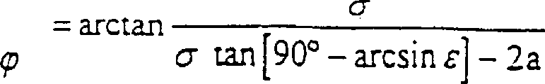
此外,如果用符号σ代替2a tan[arccos(a/R)]项,Furthermore, if the
则可得到等式I至X的以下简化表达;Then the following simplified expressions of equations I to X can be obtained;
等式(I) α=arccosεEquation (I) α = arccosε
等式(II) β=arcsinεEquation (II) β=arcsinε
等式(III) γ=90°-arcsinεEquation (III) γ=90°-arcsinε
等式(IV) UW=σEquation (IV) UW=σ
等式(V) WΩ=σtan[90°-arcsinε]Equation (V) WΩ=σtan[90°-arcsinε]
等式(VI) Tφ=σtan[90°-arcsinε]-2aEquation (VI) Tφ=σtan[90°-arcsinε]-2a
等式(VII)
等式(VIII)

等式(IX)Equation (IX)

等式XEquation X
下面对照图20至图23对截止闸阀闭合时的力加以说明。阀盘具有一个密封片44形状的密封件,见图2和图3。为简化起见,在图20至图23中只表示出唯一一个弹簧圈71。该弹簧圈可以单独构成阀盘的密封件,或者与其他薄的密封圈构成密封片组。以下假设阀盘的密封件不采用相对薄的形状,所以只设置了一个在环绕的支座或凹槽中浮动的弹簧圈71。The force when the shut-off gate valve is closed will be described below with reference to FIGS. 20 to 23 . The valve disc has a seal in the form of a sealing
当截止闸阀闭合时,弹簧圈71靠在闸阀壳体的环绕密封阀座上。由于箭头72所示的旋转闭合运动,在侧面区域73、74作用有较强的压力,它是由于密封阀座的锥形产生的,大致与倾斜平面的上升相当。When the cut-off gate valve is closed, the
在上部圆周区52和下部圆周区53并没有向内的力作用,因为弹簧圈71在此处和转动轴线(旋转中心46)相交。相应地在该圆周区52、53产生了弹簧圈71的向外作用的压力作为反作用力。所以弹簧圈71自动配合到密座。所产生的力通过弹簧圈71的弹性被均匀分布或传递。其中重要的是弹簧圈71的安置要使其垂直于流体方向可发生配准或偏离运动。In the upper
图22表示所产生的力的图解。一个被压缩的圆75以其相对弹簧圈71外径的偏移定义出不同的力。在侧面区域73、74由外部作用到弹簧圈71上的压力最大,而在上部和下部圆周区52、53则主要是从中产生的反作用力。该力当然是朝外作用的。Figure 22 shows a diagram of the forces generated. A compressed circle 75 defines different forces with its offset relative to the outer diameter of the
下面对照图24和图25对阀盘或密封座的椭圆形状加以描述。如上所述,密封座,即闸阀壳体37中的环绕密封面是具有锥顶S1的锥体的—部分。因为锥顶S1没有处在主轴线38上,所以所属的锥体截面与锥体轴线KA形成一个不等于90度的角长,并且具有一个椭圆的形状。所以环绕的密封面有两个直径,相当于数学中常用的椭圆尺寸,即一个大直径2a和一个小直径2b。其中的大直径2a在图24中相应于点A至C之间的线段。小直径2b相应于阀盘32的高度,它是由通过点p的垂直于锥体轴线KA的直线76得到的,其中该垂线与主轴线38相交于密封装置中心线39的交点56。从图中还可以看到直线76与所述锥体的母线K1和K2的交点s和t。小直径2b与沿直线76的点s至t的距离相等。The oval shape of the valve disc or sealing seat will be described below with reference to Fig. 24 and Fig. 25 . As mentioned above, the sealing seat, ie the surrounding sealing surface in the
如图24所示,点S1位于主轴线38的一条平行线77上,其中平行线77与主轴线38之间的距离等于阀盘半径rk的3倍(rk=点56至C之间的距离)。点S1在平行线77上的位置是通过密封圆55在点B(或图16至18中的点V)的切线78得到的。因此旋转中心46距离密封装置中心线39越远(截止闸阀的偏心量),则平行线77上的点S1就越向左朝密封装置中心线39的方向移动。As shown in Figure 24, the point S1 is located on a
根据图25可以得出环绕密封面的椭圆形状。一个具有锥顶Z和母线Z1、Z2的锥体具有一根锥体轴线ZA,同时它也是锥角
![]()
![]()
根据斜锥体截面的不同位置,点H可距锥体轴线ZA有较大或较小的距离。其中在图25中有若干锥体截面是从点ZS出发画出的。此外还可看出通过点H的锥体截面的椭圆的高度。该椭圆具有高度2b,它等于点H1至H2之间的距离。图25中的点H和p相应于图24中的点56和p。为表示清楚,图中还画出了分段D1和D2。Depending on the position of the oblique cone section, the point H can be at a greater or lesser distance from the cone axis ZA. Wherein in Fig. 25, several cone sections are drawn from point ZS. Furthermore, the height of the ellipse of the cone section passing through the point H can be seen. The ellipse has a
本发明所述截止闸阀的特点是,采用相对较薄的弹簧圈或密封圈,所以和已有的截止闸阀相比,其控制力矩相对较小。从理论上讲,当密封圈无限薄时,开头所述的、并且可自动闭合或自动保持的作用力将不会产生。由于闸阀采用对称结构,转动轴线位于主轴线38上=单一的偏心量,所以通过不同的压力作用在阈盘两侧的力得到平衡。用于阀盘打开和闭合所需的控制力矩相对较小。所以驱动装置的尺寸也可相应减小。The cut-off gate valve of the present invention is characterized in that a relatively thin spring ring or sealing ring is used, so compared with the existing cut-off gate valve, its control torque is relatively small. Theoretically, the forces described at the outset and which allow for self-closing or self-holding would not occur if the sealing ring were infinitely thin. Since the gate valve adopts a symmetrical structure, the rotation axis is located on the
闸阀闭合时,由于阀盘两侧的不同压力在阀盘上出现少许弯曲,弯曲量的最大值肯定出现在半高处,在图26中是沿X轴线。由于弯曲和上述锥形阀座的布置会使密封圈或弹簧圈71产生一个横向位移。但是该横向位移极小,只需要少许增加所需的控制力矩。下面对照图26和所得到的公式对弹簧圈71位移后垂直于闭合阀盘的有效力矩加以说明。该说明也适用于厚的密封圈或密封片组以及由此在阀盘两侧作用的不同力矩。在下式中有:When the gate valve is closed, due to the different pressures on both sides of the valve disc, there is a little bending on the valve disc, and the maximum value of the bending amount must appear at half height, which is along the X axis in Figure 26. Due to the bending and the arrangement of the above-mentioned conical valve seat, a lateral displacement of the sealing ring or
其中y=f(x) (XI)where y=f(x) (XI)
其中y=f(x) (XII)where y=f(x) (XII)
(XIII.)(XIII.)
(XIV.)(XIV.)
∑Mi=0=M1-(M2+ΔM) (XV.)∑Mi=0=M 1 -(M 2 +ΔM) (XV.)
ΔM=M1-M2 (XVI.)ΔM=M 1 -M 2 (XVI.)
其中(0°≤≤180°)并且
弹簧圈71连同所属的阀盘构成了一个椭圆形状的表面,其长直径为2a(宽度),短直径为2b(高度)。阀盘的旋转中心46相对于宽度2a的平分线(y轴)错开布置。结合阀盘两侧的压差可产生一个合成扭矩,它根据方向或符号对阀盘的调节加以促进或缓阻。通过旋转中心46确定的垂直线的两侧表面面积可按照等式(XI.)和等式(XII.)计算。作为函数y=f(x)在这里要使用一个适用于椭圆的函数。基于一般的公式y=f(x)可以采用等式(XI.)至等式(XVIII.)计算其他形状阀盘上的力矩。所必需的仅仅是函数的可确定性。有效杠杆臂长可根据压力重心SX1和SX2的位置确定,见等式(XIII.)和等式(XIV.)。合成力矩参见等式(XV.)至等式(XVIII.),它是通过各个力矩之差得出的,其中该力矩通过有效压力p,所计算的面积A1和A2以及有效杠杆臂长SX1和CX2确定的。在等式(XVIII.)中代入了相应的数值,并且尽量进行了化简。对于积分有效的端点c、d和e见图26所示。c和e同时是弹簧圈71在其横向位移之后的侧面边缘上的点,或者总是在所观察的阀盘侧面上有效的侧面边缘点,而d则是旋转中心46确定的轴线位置。The
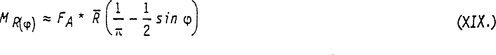
等式(XIX.)描述了图20中在弹簧圈71圆周上产生的弯曲力矩的一般形式,它与半径R相对水平线的夹角相关,该弯曲力矩是由于环绕密封面DF的锥形阀座在阀盘闭合时,侧面部分受压而引起的。FA表示有效作用力。

图20和图22的附表
最后,图27还表示出弹簧圈71安装在阀盘32上的情况。弹簧圈71被固定在一个环形槽79中,该槽是通过阀盘32和一个以螺钉连接在阀盘上的固定环80构成的,固定环的外径稍小于弹簧圈71的外径。位于该固定环80对面,即在弹簧圈的另一侧设置了一个密封圈82,它位于阀盘32的轴向槽81内,所以被阀盘32截止的介质不会流过内部的弹簧圈71。Finally, FIG. 27 also shows the installation of the
图27还包含一个特殊之处。所画出的椭圆E代表一个锥体截面,它位于图中弹簧圈71的右侧,沿直线LR布置。在该例中,椭圆E被主轴线38分成两半,所述主轴线通过旋转中心46和点56。如果用位于弹簧圈71左侧的锥体截面来代替它,则相应的锥体截面线(未画出)与所属椭圆的等分线之间的交点刚好位于点PL,在图27中,它被标为小十字。Figure 27 also contains a special feature. The drawn ellipse E represents a cone section, which is located on the right side of the
环绕的密封面DF的锥形座是通过锥顶S1的参数精确定义的,并且得出了这里所说的主锥形。以其他锥体为基础的锥形座并非不行。这种锥体也是可能的,比起S1其锥顶更加紧靠主轴线38,同时也更加紧靠密封装置中心线39,见图24。这特别是用于锥顶位于主锥体之内的情况,即位于母线K1和K2之间。The conical seat of the surrounding sealing surface DF is precisely defined by the parameters of the cone S1 and results in what is referred to here as the main cone. Conical seats based on other cones are not out of the question. Such a cone is also possible, with the tip of the cone being closer to the
在以上所述的实施例中,作为锥体始终是采用圆锥。实际上也可采用其他形状的锥体,例如其用于产生环绕密封面的锥体截面为圆形。一般而言,垂直于锥体轴线的锥体截面应当具有完全凸起的母线,即没有下凹的部分。重要的是阀盘仅有一个偏心,转动轴线距主轴线充其量有一很小的距离(很小的双重偏心),从而对不同的流动方向仅产生很小的力矩差。In the embodiments described above, a cone is always used as the cone. Cones of other shapes can also be used in practice, for example the cone whose cross-section is circular for producing the surrounding sealing surface. In general, a cone section perpendicular to the cone axis should have a fully convex generatrix, ie, no concave portions. What is important is that the valve disc has only one eccentricity and that the axis of rotation has at best a small distance from the main axis (small double eccentricity), so that only small torque differences are produced for the different flow directions.
Claims (15)
Applications Claiming Priority (2)
| Application Number | Priority Date | Filing Date | Title |
|---|---|---|---|
| DE19918128A DE19918128A1 (en) | 1999-04-21 | 1999-04-21 | Shut-off valve for pressurized containers or pipe lines has valve plate which closes automatically in both directions of flow |
| DE19918128.4 | 1999-04-21 |
Publications (2)
| Publication Number | Publication Date |
|---|---|
| CN1349597A CN1349597A (en) | 2002-05-15 |
| CN1237294C true CN1237294C (en) | 2006-01-18 |
Family
ID=7905385
Family Applications (1)
| Application Number | Title | Priority Date | Filing Date |
|---|---|---|---|
| CNB008063702A Expired - Fee Related CN1237294C (en) | 1999-04-21 | 2000-04-20 | Devices for controlling the flow medium |
Country Status (21)
| Country | Link |
|---|---|
| US (1) | US6702257B1 (en) |
| EP (1) | EP1169588B1 (en) |
| KR (1) | KR100699751B1 (en) |
| CN (1) | CN1237294C (en) |
| AT (1) | ATE261074T1 (en) |
| AU (1) | AU761816B2 (en) |
| CA (1) | CA2370996C (en) |
| CZ (1) | CZ295345B6 (en) |
| DE (2) | DE19918128A1 (en) |
| DK (1) | DK1169588T3 (en) |
| ES (1) | ES2215647T3 (en) |
| HK (1) | HK1045555B (en) |
| MX (1) | MXPA01010626A (en) |
| NO (1) | NO320240B1 (en) |
| PL (1) | PL194564B1 (en) |
| PT (1) | PT1169588E (en) |
| RS (1) | RS49748B (en) |
| RU (1) | RU2243435C2 (en) |
| SK (1) | SK285116B6 (en) |
| WO (1) | WO2000065261A1 (en) |
| ZA (1) | ZA200108574B (en) |
Families Citing this family (35)
| Publication number | Priority date | Publication date | Assignee | Title |
|---|---|---|---|---|
| CN100342161C (en) * | 2002-08-14 | 2007-10-10 | 北方微机股份公司 | Butterfly valve for controlling a GAS pressure |
| DE10251385A1 (en) * | 2002-11-01 | 2004-05-13 | Siemens Ag | Valve |
| JP2004183711A (en) * | 2002-11-29 | 2004-07-02 | Asahi Organic Chem Ind Co Ltd | Seat ring for butterfly valves |
| ITNO20030001U1 (en) * | 2003-01-14 | 2004-07-15 | Pettinaroli Flii Spa | BALL VALVE WITH PARTICULAR FEATURE OF PERCENTAGE INCREASE OF THE FLOW, OBTAINABLE IN THE MANEUVERING ARC OF 90 °, FROM THE CLOSING POSITION TO THE OPENING POSITION. |
| DE10310744A1 (en) * | 2003-03-10 | 2004-11-11 | Siemens Ag | Part of a throttle valve assembly |
| DE202004001919U1 (en) * | 2004-02-09 | 2005-06-23 | Kutzner + Weber Gmbh | Shut-off device for a gas pipe |
| RU2267019C1 (en) * | 2004-04-27 | 2005-12-27 | Открытое акционерное общество Научно-производственное объединение "Искра" | Cooling system of gas-transfer set gas-turbine engine |
| KR100666136B1 (en) * | 2006-03-08 | 2007-01-09 | 백완기 | Variable air volume regulator |
| AT505121B1 (en) | 2007-04-24 | 2009-08-15 | Tropper Maschinen Und Anlagen | VEHICLE WITH A MIXING TANK |
| US20090152270A1 (en) * | 2007-12-12 | 2009-06-18 | Thomas George Crowe | Orientation system for a closure |
| FR2933469B1 (en) * | 2008-07-01 | 2013-01-11 | Valeo Sys Controle Moteur Sas | VALVE BODY ASSEMBLY AND SEAL ASSEMBLY, VALVE BODY ASSEMBLY, SEAL BODY AND PIPE, SEAL FOR ASSEMBLY |
| DE102008047187B4 (en) * | 2008-09-15 | 2014-06-05 | Audi Ag | Machine with a partial circuits having reliable coolant circuit |
| CZ20667U1 (en) | 2009-12-16 | 2010-03-22 | Technology Center, S.R.O. | Shutting-down flap body |
| FR2954442B1 (en) * | 2009-12-23 | 2012-10-26 | Valeo Sys Controle Moteur Sas | VALVE FOR USE, IN PARTICULAR, TO BE IMPLANTED IN AN AIR INTAKE CIRCUIT OF A THERMAL ENGINE |
| FR2954443B1 (en) * | 2009-12-23 | 2012-05-18 | Valeo Sys Controle Moteur Sas | VALVE FOR USE, IN PARTICULAR, TO BE IMPLANTED IN AN AIR INTAKE CIRCUIT OF A THERMAL ENGINE |
| JP2016506477A (en) * | 2012-04-25 | 2016-03-03 | キユートルコ・インコーポレーテツドQTRCO,Inc. | Double eccentric butterfly valve |
| RU2492383C1 (en) * | 2012-08-20 | 2013-09-10 | Армен Арамаисович Оганесян | Rotary lock |
| JP2016537559A (en) * | 2013-08-30 | 2016-12-01 | ドングァン リヒテック エレクトロニクス カンパニー リミテッド | Fluid cylinder |
| US9951876B2 (en) * | 2013-12-25 | 2018-04-24 | Aisan Kogyo Kabushiki Kaisha | Double eccentric valve |
| JP5759647B1 (en) * | 2013-12-25 | 2015-08-05 | 愛三工業株式会社 | Double eccentric valve |
| US9897214B2 (en) * | 2015-11-04 | 2018-02-20 | Honeywell International Inc. | Off-set and sine-wave shaped butterfly plate to reduce aero-torque and reduce actuator size |
| JP6768427B2 (en) * | 2016-06-01 | 2020-10-14 | 愛三工業株式会社 | Double eccentric valve |
| CN106523719A (en) * | 2016-11-29 | 2017-03-22 | 陈曙光 | Concave plate three-eccentric center butterfly valve |
| CN106870864A (en) * | 2017-04-25 | 2017-06-20 | 姜丽莉 | A kind of pipe flow speed control structure |
| WO2019211505A1 (en) * | 2018-05-02 | 2019-11-07 | Metso Flow Control Oy | A valve and a closure member |
| EP3567287B1 (en) * | 2018-05-07 | 2021-03-03 | Gregor Gaida | Quintuple asymmetrically constructed butterfly valve |
| CN113490808B (en) * | 2019-02-28 | 2025-06-03 | 株式会社开滋 | Double eccentric butterfly valve body and double eccentric butterfly valve |
| JP6959953B2 (en) * | 2019-03-26 | 2021-11-05 | Ckd株式会社 | Butterfly valve |
| RU194385U1 (en) * | 2019-08-15 | 2019-12-09 | Акционерное общество "Машиностроительный завод "Армалит" | DISC SHUTTER WITH TRIPLE ECCENTRICITY |
| US11953113B2 (en) | 2020-02-14 | 2024-04-09 | Crane Chempharma & Energy Corp. | Valve with unobstructed flow path having increased flow coefficient |
| US11946557B2 (en) | 2020-02-14 | 2024-04-02 | Crane Chempharma & Energy Corp. | Valve with unobstructed flow path having increased flow coefficient |
| US11841089B2 (en) * | 2020-02-14 | 2023-12-12 | Crane Chempharma & Energy Corp. | Valve with unobstructed flow path having increased flow coefficient |
| JP7500249B2 (en) * | 2020-03-31 | 2024-06-17 | 株式会社キッツ | Double eccentric butterfly valve and its manufacturing method |
| RU202691U1 (en) * | 2020-09-08 | 2021-03-03 | Общество с ограниченной ответственностью "Управляющая компания "НБМ" | Butterfly valve with triple eccentricity |
| KR102268251B1 (en) * | 2020-12-10 | 2021-06-23 | 한국유니콤밸브주식회사 | Butterfly valve with quintuple offset structure |
Family Cites Families (11)
| Publication number | Priority date | Publication date | Assignee | Title |
|---|---|---|---|---|
| US3945398A (en) | 1973-06-29 | 1976-03-23 | Henry Masheder | Check valves |
| SE383402B (en) * | 1973-10-15 | 1976-03-08 | Saab Scania Ab | SPRINKLE VALVE |
| GB1536837A (en) * | 1977-04-05 | 1978-12-20 | Kamyr Valves | Butterfly valve |
| DE2945963A1 (en) * | 1979-11-14 | 1981-05-21 | Helmut 4630 Bochum Behrens | DOUBLE ECCENTRIC BUTTERFLY VALVE |
| US4480815A (en) * | 1982-11-19 | 1984-11-06 | Saab-Scania Aktiebolag | Sealing device for valves |
| FR2554539B1 (en) * | 1983-11-07 | 1986-01-31 | Verdelet Alain | IMPROVED BUTTERFLY VALVE |
| SE456112C (en) * | 1987-01-02 | 1996-04-29 | Somas Ventiler | Butterfly Valve |
| DE4035120A1 (en) * | 1990-11-05 | 1992-05-07 | Siemens Ag | CONTROL VALVE FOR LIQUID OR GASEOUS MEDIA |
| FR2674599B1 (en) * | 1991-03-29 | 1993-05-21 | Guichon International | BUTTERFLY TAP. |
| GB9310025D0 (en) * | 1993-05-15 | 1993-06-30 | Btr Plc | Butterfly valve |
| JP3108353B2 (en) | 1995-12-19 | 2000-11-13 | 宮入 一弘 | Butterfly valve |
-
1999
- 1999-04-21 DE DE19918128A patent/DE19918128A1/en not_active Withdrawn
-
2000
- 2000-04-20 DK DK00925234T patent/DK1169588T3/en active
- 2000-04-20 KR KR1020017013331A patent/KR100699751B1/en not_active Expired - Fee Related
- 2000-04-20 EP EP00925234A patent/EP1169588B1/en not_active Expired - Lifetime
- 2000-04-20 CN CNB008063702A patent/CN1237294C/en not_active Expired - Fee Related
- 2000-04-20 AU AU44023/00A patent/AU761816B2/en not_active Ceased
- 2000-04-20 PT PT00925234T patent/PT1169588E/en unknown
- 2000-04-20 DE DE50005518T patent/DE50005518D1/en not_active Expired - Fee Related
- 2000-04-20 CZ CZ20013659A patent/CZ295345B6/en not_active IP Right Cessation
- 2000-04-20 HK HK02107055.5A patent/HK1045555B/en not_active IP Right Cessation
- 2000-04-20 MX MXPA01010626A patent/MXPA01010626A/en active IP Right Grant
- 2000-04-20 CA CA002370996A patent/CA2370996C/en not_active Expired - Fee Related
- 2000-04-20 SK SK1466-2001A patent/SK285116B6/en not_active IP Right Cessation
- 2000-04-20 PL PL00351504A patent/PL194564B1/en unknown
- 2000-04-20 ES ES00925234T patent/ES2215647T3/en not_active Expired - Lifetime
- 2000-04-20 WO PCT/EP2000/003645 patent/WO2000065261A1/en not_active Ceased
- 2000-04-20 AT AT00925234T patent/ATE261074T1/en not_active IP Right Cessation
- 2000-04-20 US US09/959,370 patent/US6702257B1/en not_active Expired - Fee Related
- 2000-04-20 RU RU2001131355/06A patent/RU2243435C2/en not_active IP Right Cessation
- 2000-04-20 RS YUP-736/01A patent/RS49748B/en unknown
-
2001
- 2001-10-18 ZA ZA200108574A patent/ZA200108574B/en unknown
- 2001-10-19 NO NO20015127A patent/NO320240B1/en unknown
Also Published As
| Publication number | Publication date |
|---|---|
| ATE261074T1 (en) | 2004-03-15 |
| US6702257B1 (en) | 2004-03-09 |
| CZ20013659A3 (en) | 2002-04-17 |
| NO20015127L (en) | 2001-10-19 |
| NO20015127D0 (en) | 2001-10-19 |
| ES2215647T3 (en) | 2004-10-16 |
| SK14662001A3 (en) | 2002-06-04 |
| EP1169588B1 (en) | 2004-03-03 |
| CA2370996A1 (en) | 2000-11-02 |
| PT1169588E (en) | 2004-07-30 |
| CN1349597A (en) | 2002-05-15 |
| HK1045555A1 (en) | 2002-11-29 |
| DE50005518D1 (en) | 2004-04-08 |
| WO2000065261A1 (en) | 2000-11-02 |
| PL194564B1 (en) | 2007-06-29 |
| KR20020019904A (en) | 2002-03-13 |
| CZ295345B6 (en) | 2005-07-13 |
| NO320240B1 (en) | 2005-11-14 |
| AU761816B2 (en) | 2003-06-12 |
| DK1169588T3 (en) | 2004-07-12 |
| ZA200108574B (en) | 2003-01-20 |
| AU4402300A (en) | 2000-11-10 |
| SK285116B6 (en) | 2006-06-01 |
| DE19918128A1 (en) | 2000-10-26 |
| EP1169588A1 (en) | 2002-01-09 |
| PL351504A1 (en) | 2003-04-22 |
| CA2370996C (en) | 2005-11-15 |
| RU2243435C2 (en) | 2004-12-27 |
| MXPA01010626A (en) | 2003-09-04 |
| KR100699751B1 (en) | 2007-03-27 |
| RS49748B (en) | 2008-04-04 |
| HK1045555B (en) | 2006-09-29 |
| YU73601A (en) | 2003-02-28 |
Similar Documents
| Publication | Publication Date | Title |
|---|---|---|
| CN1237294C (en) | Devices for controlling the flow medium | |
| TWI555934B (en) | Eccentric valve and manufacture method thereof | |
| US8960643B2 (en) | Double offset ball member usable in ball valves and other flow control applications | |
| CN102350658B (en) | Ultra-precise processing method for circular conical surface of fluid static pressure sealing ring for nuclear primary pump | |
| CN101842623A (en) | Valve element mechanism for exhaust gas circulation valve | |
| CN102581728A (en) | Machining method for complex surfaces of liquid hybrid type mechanical seal rings | |
| CN1965188A (en) | Fluid valve control members having contoured sealing surfaces | |
| JP6816872B2 (en) | Gate valve structure and its manufacturing method | |
| CN1596332A (en) | rotary volumetric machine | |
| CN1237277C (en) | Vortex compressor | |
| JPH0875013A (en) | Rotation type shutoff valve | |
| CN102806508B (en) | Complex molded surface grinding method for three-axis linkage mechanical sealing ring | |
| TW201903306A (en) | Shaft sealing device | |
| CN102785149B (en) | Grinding method of complex shaped surface of four-shaft linkage mechanical seal ring | |
| CN113618613B (en) | Burnishing device of casting aluminum alloy material | |
| TWI574774B (en) | Spindle structure | |
| CN1179819A (en) | Angle entry rotary valve | |
| CN1667310A (en) | Synthetic resin ball universal joint | |
| CN102785148B (en) | Grinding method for complex surface of mechanical seal ring | |
| EP2703700B1 (en) | Diaphragm valve having spherically-shaped valve body and diaphragm sealing surface | |
| TWI476339B (en) | Tri-shift valve with a symmetric drain proof ring | |
| TWM449215U (en) | Cone-type exterior tangent line of valve and unparallel shaft three eccentric valve of valve assembly | |
| KR20140135065A (en) | Throttle valve for car and its manufacturing method | |
| TWI688449B (en) | Automatically balanced tool holder | |
| CN116587014A (en) | Air seal components for air bearing spindles and ultra-precision machine tools |
Legal Events
| Date | Code | Title | Description |
|---|---|---|---|
| C06 | Publication | ||
| PB01 | Publication | ||
| C10 | Entry into substantive examination | ||
| SE01 | Entry into force of request for substantive examination | ||
| C14 | Grant of patent or utility model | ||
| GR01 | Patent grant | ||
| C17 | Cessation of patent right | ||
| CF01 | Termination of patent right due to non-payment of annual fee |
Granted publication date: 20060118 |